WO2022113833A1 - レーザ加工方法、レーザ加工機、及び加工プログラム作成装置 - Google Patents
レーザ加工方法、レーザ加工機、及び加工プログラム作成装置 Download PDFInfo
- Publication number
- WO2022113833A1 WO2022113833A1 PCT/JP2021/042121 JP2021042121W WO2022113833A1 WO 2022113833 A1 WO2022113833 A1 WO 2022113833A1 JP 2021042121 W JP2021042121 W JP 2021042121W WO 2022113833 A1 WO2022113833 A1 WO 2022113833A1
- Authority
- WO
- WIPO (PCT)
- Prior art keywords
- line
- hole
- dividing line
- correction
- dividing
- Prior art date
- Legal status (The legal status is an assumption and is not a legal conclusion. Google has not performed a legal analysis and makes no representation as to the accuracy of the status listed.)
- Ceased
Links
Images





Classifications
-
- B—PERFORMING OPERATIONS; TRANSPORTING
- B23—MACHINE TOOLS; METAL-WORKING NOT OTHERWISE PROVIDED FOR
- B23K—SOLDERING OR UNSOLDERING; WELDING; CLADDING OR PLATING BY SOLDERING OR WELDING; CUTTING BY APPLYING HEAT LOCALLY, e.g. FLAME CUTTING; WORKING BY LASER BEAM
- B23K26/00—Working by laser beam, e.g. welding, cutting or boring
- B23K26/08—Devices involving relative movement between laser beam and workpiece
- B23K26/0869—Devices involving movement of the laser head in at least one axial direction
- B23K26/0876—Devices involving movement of the laser head in at least one axial direction in at least two axial directions
- B23K26/0884—Devices involving movement of the laser head in at least one axial direction in at least two axial directions in at least three axial directions, e.g. manipulators, robots
-
- B—PERFORMING OPERATIONS; TRANSPORTING
- B23—MACHINE TOOLS; METAL-WORKING NOT OTHERWISE PROVIDED FOR
- B23K—SOLDERING OR UNSOLDERING; WELDING; CLADDING OR PLATING BY SOLDERING OR WELDING; CUTTING BY APPLYING HEAT LOCALLY, e.g. FLAME CUTTING; WORKING BY LASER BEAM
- B23K26/00—Working by laser beam, e.g. welding, cutting or boring
- B23K26/36—Removing material
- B23K26/38—Removing material by boring or cutting
-
- B—PERFORMING OPERATIONS; TRANSPORTING
- B23—MACHINE TOOLS; METAL-WORKING NOT OTHERWISE PROVIDED FOR
- B23K—SOLDERING OR UNSOLDERING; WELDING; CLADDING OR PLATING BY SOLDERING OR WELDING; CUTTING BY APPLYING HEAT LOCALLY, e.g. FLAME CUTTING; WORKING BY LASER BEAM
- B23K26/00—Working by laser beam, e.g. welding, cutting or boring
- B23K26/36—Removing material
- B23K26/38—Removing material by boring or cutting
- B23K26/382—Removing material by boring or cutting by boring
- B23K26/388—Trepanning, i.e. boring by moving the beam spot about an axis
-
- B—PERFORMING OPERATIONS; TRANSPORTING
- B23—MACHINE TOOLS; METAL-WORKING NOT OTHERWISE PROVIDED FOR
- B23K—SOLDERING OR UNSOLDERING; WELDING; CLADDING OR PLATING BY SOLDERING OR WELDING; CUTTING BY APPLYING HEAT LOCALLY, e.g. FLAME CUTTING; WORKING BY LASER BEAM
- B23K37/00—Auxiliary devices or processes, not specially adapted for a procedure covered by only one of the other main groups of this subclass
- B23K37/02—Carriages for supporting the welding or cutting element
- B23K37/0211—Carriages for supporting the welding or cutting element travelling on a guide member, e.g. rail, track
- B23K37/0235—Carriages for supporting the welding or cutting element travelling on a guide member, e.g. rail, track the guide member forming part of a portal
-
- B—PERFORMING OPERATIONS; TRANSPORTING
- B23—MACHINE TOOLS; METAL-WORKING NOT OTHERWISE PROVIDED FOR
- B23K—SOLDERING OR UNSOLDERING; WELDING; CLADDING OR PLATING BY SOLDERING OR WELDING; CUTTING BY APPLYING HEAT LOCALLY, e.g. FLAME CUTTING; WORKING BY LASER BEAM
- B23K37/00—Auxiliary devices or processes, not specially adapted for a procedure covered by only one of the other main groups of this subclass
- B23K37/04—Auxiliary devices or processes, not specially adapted for a procedure covered by only one of the other main groups of this subclass for holding or positioning work
- B23K37/0408—Auxiliary devices or processes, not specially adapted for a procedure covered by only one of the other main groups of this subclass for holding or positioning work for planar work
-
- B—PERFORMING OPERATIONS; TRANSPORTING
- B23—MACHINE TOOLS; METAL-WORKING NOT OTHERWISE PROVIDED FOR
- B23K—SOLDERING OR UNSOLDERING; WELDING; CLADDING OR PLATING BY SOLDERING OR WELDING; CUTTING BY APPLYING HEAT LOCALLY, e.g. FLAME CUTTING; WORKING BY LASER BEAM
- B23K2101/00—Articles made by soldering, welding or cutting
- B23K2101/18—Sheet panels
Definitions
- This disclosure relates to a laser processing method, a laser processing machine, and a processing program creating device.
- the laser processing machine irradiates a sheet metal placed on a table on which a plurality of skids are arranged with a laser beam to cut the sheet metal to produce a part having a predetermined shape. If the part has a hole formed inside, the laser machine cuts the circumference of the hole forming region where the hole is formed, and then cuts the circumference of the part. The part that should be cut and removed from the part is called scrap.
- the laser processing machine divides the hole forming region into a plurality of small scraps when forming a hole having a predetermined size or more (see Patent Document 1 or 2). ).
- the laser machining machine cuts the hole forming region along the dividing line set in the hole forming region, and then cuts the sheet metal along the hole forming line around the hole forming region. At this time, if the angle between the dividing line and the drilling line or the angle formed by the tangent of the drilling line at the connecting point where the dividing line and the dividing line are connected to the drilling line is small, the metal is excessively formed in the vicinity of the connecting point. A phenomenon called melting burning may occur.
- a hole drilling line for forming a hole in a part produced by cutting a sheet metal is set, and a hole surrounded by the hole drilling line is set.
- One or a plurality of dividing lines consisting of straight lines are set in the formation region, and the angle formed by the dividing line and the drilling line at the first connecting point where the dividing line is connected to the drilling line, or the above-mentioned
- the angle formed by the dividing line and the tangent line of the drilled line at the first connecting point is defined as the connecting angle of the dividing line, and the smaller connection angle of the two connecting angles sandwiching the dividing line is to be determined.
- connection angle it is determined whether or not the connection angle of the determination target is smaller than the predetermined angle, and when the connection angle of the determination target is smaller than the predetermined angle, the inside of the hole forming region of the dividing line
- the line segment between the auxiliary line and the hole drilling line offset inward by a predetermined distance from the set hole drilling line is different from the first connecting point from the position where the dividing line intersects the auxiliary line.
- the dividing line is corrected so as to be replaced with a correction dividing line consisting of a straight line or a curve up to the second connecting point connected to the hole processing line, and at the second connecting point, the correction dividing line and the hole processing line are replaced.
- the angle formed by the correction dividing line or the angle formed by the tangent line of the hole processing line at the second connecting point is defined as the connection angle of the correction dividing line, and of the two connection angles sandwiching the correction dividing line.
- the correction division line With the connection angle on the same side as the connection angle of the determination target as the correction connection angle, the correction division line is set so that the correction connection angle is larger than the connection angle of the determination target, and at least the corrected division is performed.
- a laser beam is irradiated along one or a plurality of dividing lines including a line to divide the hole forming region into a plurality of scraps, and a laser beam is irradiated along the drilling line to cut the hole forming region.
- a laser processing method for forming the hole in the sheet metal is provided.
- the processing machine main body that cuts the sheet metal by irradiating the sheet metal with a laser beam and the processing machine main body cuts the sheet metal to produce a part.
- the control device includes a control device for controlling the machine body, and the control device divides a hole forming region surrounded by a hole forming line set for forming a hole in the part into a plurality of scraps and then divides the hole forming region into a plurality of scraps.
- the drilling line is cut to form the hole, the dividing line and the drilling line are connected at a connection point where one or more dividing lines for dividing the hole forming region are connected to the drilling line.
- the angle formed by the dividing line or the angle formed by the tangent line of the dividing line and the tangent line of the hole processing line at the connecting point is defined as the connection angle of the dividing line, and the smaller connection angle of the two connection angles sandwiching the dividing line is
- the hole forming region is divided by a dividing line that is bent at a position where the dividing line intersects with an auxiliary line that is offset inward from the hole processing line set in the hole forming region so as to have a predetermined angle or more.
- a laser processing machine for controlling the processing machine main body is provided.
- the hole forming region surrounded by the hole forming line set for forming the hole is divided into the dividing line based on the part graphic data indicating the part having the hole.
- the hole division necessity determination unit determines whether or not it is necessary to divide by the hole division necessity determination unit and that the hole formation region needs to be divided by the division line.
- the hole formation is performed.
- the angle between the dividing line and the drilling line at the first connecting point where the dividing line sets one or more dividing lines in the region and the dividing line is connected to the hole drilling line, or the above.
- the angle formed by the dividing line and the tangent of the drilling line at the first connecting point is defined as the connecting angle of the dividing line, and the smaller connection angle of the two connecting angles sandwiching the dividing line is to be determined.
- the connection angle of the determination target is determined by the division line correction necessity determination unit for determining whether or not the connection angle of the determination target is smaller than the predetermined angle, and the division line correction necessity determination unit.
- the line segment between the auxiliary line and the hole drilling line which is offset inward by a predetermined distance from the hole drilling line set in the hole forming region, among the dividing lines.
- the dividing line is replaced with a correction dividing line consisting of a straight line or a curve from the position where the dividing line intersects the auxiliary line to the second connecting point connected to the hole processing line different from the first connecting point.
- a machining program creation device including a dividing line correction unit for correcting the above angle is provided.
- the dividing line correction unit has an angle formed by the correction dividing line and the hole machining line at the second connecting point, or the correction dividing line and the second connecting point.
- the angle formed by the tangent of the hole processing line in the above is the connection angle of the correction dividing line, and the connection angle on the same side as the connection angle of the determination target among the two connection angles sandwiching the correction division line is the correction connection angle.
- the correction dividing line is set so that the correction connection angle is larger than the connection angle of the determination target.
- the machining program creation device having the above configuration allocates a cutting path of the dividing line in the hole forming region based on the part graphic data and the dividing line set by the dividing line correction unit, and makes a hole in the hole machining line.
- the cutting route setting unit for allocating the cutting route for forming the above and the NC device controls the laser processing machine to cut the sheet metal based on the cutting route set by the cutting route setting unit to produce the part. It is further provided with an NC data creation unit for creating NC data for the purpose.
- a dividing line that suppresses the occurrence of processing defects is formed to form a sheet metal. Can be processed.
- FIG. 1 is a diagram showing an overall configuration example of a laser machine of one or more embodiments.
- FIG. 2 is a plan view showing a first example of a part having a hole.
- FIG. 3 is a plan view showing a state in which the hole forming region of the part shown in FIG. 2 is divided by one or a plurality of dividing lines.
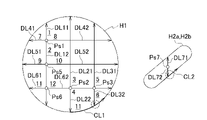
- FIG. 4 is a diagram showing an example of a specific cutting process when the hole forming region of the part shown in FIG. 2 is divided by one or a plurality of dividing lines shown in FIG.
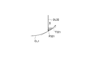
- FIG. 5 is a partially enlarged view in FIG. 4 for explaining the reason why processing defects occur.
- FIG. 4 is a diagram showing an overall configuration example of a laser machine of one or more embodiments.
- FIG. 2 is a plan view showing a first example of a part having a hole.
- FIG. 3 is a plan view showing a state in which the hole forming region of the part shown in FIG. 2 is divided by one or a plurality of
- FIG. 6 is a plan view showing a position where burning that causes machining defects is likely to occur when the hole forming region of the part is divided by one or a plurality of dividing lines as shown in FIG.
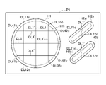
- FIG. 7 is a plan view showing a state in which the hole forming region of the part shown in FIG. 2 is divided by one or a plurality of dividing lines including a correction dividing line.
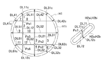
- FIG. 8 is a diagram showing an example of a specific cutting process when the hole forming region of the part shown in FIG. 2 is divided by one or a plurality of dividing lines including the correction dividing line shown in FIG. 7.
- FIG. 9 is a partially enlarged view in FIG. 8 showing the details of the correction dividing line with the correction dividing line as a straight line.
- FIG. 8 is a partially enlarged view in FIG. 8 showing the details of the correction dividing line with the correction dividing line as a straight line.
- FIG. 10 is a partially enlarged view showing the details of the correction dividing line with the correction dividing line as a curve.
- FIG. 11 is a plan view showing a second example of a part having a hole.
- FIG. 12 is a partially enlarged view showing a method of setting a correction dividing line when an offset line cannot be set in the hole forming region.
- FIG. 13 is a flowchart showing a process of creating a machining program by the machining program creating apparatus of one or more embodiments.
- FIG. 14 is a block diagram showing a functional configuration example of a CAM device for creating a machining program.
- a table 12 for placing a sheet metal W which is a material to be processed, is provided on the base 10.
- a plurality of skids 13 made of iron plates are arranged in the X direction.
- a plurality of triangular protrusions are formed on the upper end portion of the skid 13. Therefore, the sheet metal W is supported by a plurality of protrusions.
- the laser processing machine 100 includes a gate-shaped frame 14 arranged so as to straddle the table 12.
- the frame 14 has side frames 141 and 142 and an upper frame 143.
- the frame 14 is configured to move in the X direction along the rail 11 in the X direction formed on the side surface of the base 10.
- a carriage 15 that can move in the Y direction is provided in the upper frame 143.
- a processing head 16 that emits a laser beam is attached to the carriage 15.
- the machining head 16 is configured to arbitrarily move in the X and Y directions above the sheet metal W.
- the processing head 16 is also movable in the Z direction.
- the carriage 15 to which the base 10, the table 12 on which the skid 13 is arranged, the frame 14, and the processing head 16 are attached constitutes the processing machine main body 60.
- the NC device 50 controls the processing machine main body 60.
- the NC device 50 is an example of a control device that controls the processing machine main body 60.
- An operation pendant 51 connected to the NC device 50 is attached to the frame 14.
- the operation pendant 51 has a display unit 511 and an operation unit 512.
- the display unit 511 displays various types of information.
- the operation pendant 51 supplies various instruction signals to the NC device 50 by the operator operating the operation unit 512.
- a CAD (Computer Aided Design) device 1, a CAM (Computer Aided Manufacturing) device 2, and a database 3 are connected to the NC device 50 via a network.
- the CAD device 1 and the CAM device 2 are composed of computer devices.
- the CAD device 1 and the CAM device 2 may be configured by separate computer devices, or may be configured by one computer device.
- the CAD device 1 generates graphic data of a part produced by the laser processing machine 100.
- the CAM device 2 creates a processing program for the laser processing machine 100 to cut the sheet metal W to produce a part based on the graphic data of the part (and the graphic data of the sheet metal).
- the CAM device 2 functions as a machining program creating device of one or more embodiments.
- the machining program may be supplied to the NC device 50 or may be supplied to the database 3 and stored. If the machining program is stored in the database 3, the NC apparatus 50 reads the machining program corresponding to the part to be manufactured from the database 3. The NC device 50 controls the machining machine main body 60 based on the machining program.
- the laser processing machine 100 (processing machine main body 60) irradiates the sheet metal W with a laser beam while moving the processing head 16 in the X direction or the Y direction to cut the sheet metal W, and one or a plurality of parts are separated from the sheet metal W. break the ice.
- the sheet metal W is sprayed with an assist gas in accordance with the irradiation of the laser beam. In FIG. 1, the configuration for blowing the assist gas is omitted.
- Part P1 is a part having one round hole and two oblong holes.
- the laser machining machine 100 cuts the circular hole drilling line H1
- a round hole is formed, and when the oblong hole drilling lines H2a and H2b are cut, an oblong hole is formed.
- An oval hole is a figure in which a semicircular arc is connected to both ends of two parallel straight lines of the same length. If the outer shape of the part P1 is cut after the laser processing machine 100 forms a round hole and an oblong round hole, the part P1 is cut out from the sheet metal W.
- the X direction is the direction in which the plurality of skids 13 shown in FIG. 1 are arranged
- the Y direction is the direction along the plane of the skids 13 orthogonal to the X direction.
- the laser machining machine 100 divides the hole forming region in the hole machining line H1 by a plurality of dividing lines. Then, it is assumed that the hole forming region in the hole machining lines H2a and H2b is divided by one dividing line for each.
- the hole forming region in the hole processing line H1 is divided into 16 by the dividing lines DL1 to DL3 in the Y direction and the dividing lines DL4 to DL6 in the X direction.
- the hole forming region in the hole processing lines H2a and H2b is divided into two by the dividing line DL7 in the Y direction.
- each hole forming region in the drilling line H1 and the hole forming region in the drilling lines H2a and H2b are divided by the dividing lines DL1 to DL7, specifically, each hole forming region is as shown in FIG. 4 as an example. Be disconnected.
- the underlined numbers indicate an example of the cutting process and its order.
- the laser processing machine 100 opens the piercing Ps1 in the hole forming region of the hole processing line H1, cuts the dividing line DL11 from the piercing Ps1 upward to the hole processing line H1, and subsequently lowers from the piercing Ps1.
- the dividing line DL12 up to the hole processing line H1 is cut.
- the laser processing machine 100 further opens the piercing Ps2, cuts the dividing line DL21 from the piercing Ps2 upward to the hole processing line H1, and subsequently cuts the dividing line DL22 from the piercing Ps2 to the hole processing line H1 downward. ..
- the laser processing machine 100 further opens the piercing Ps3, cuts the dividing line DL31 from the piercing Ps3 upward to the hole processing line H1, and subsequently cuts the dividing line DL32 from the piercing Ps3 to the hole processing line H1 downward. ..
- the laser machining machine 100 cuts the dividing line DL41 from the piercing Ps1 to the hole processing line H1 to the left, and subsequently cuts the dividing line DL42 from the piercing Ps1 to the hole processing line H1 to the right.
- the laser machine 100 further opens the pierced earrings Ps5, cuts the dividing line DL51 from the pierced earrings Ps5 to the left side to the hole processing line H1, and subsequently cuts the dividing line DL52 from the pierced earrings Ps5 to the right side to the hole processing line H1. Disconnect.
- the laser machining machine 100 further opens the pierced earrings Ps6, cuts the dividing line DL61 from the pierced earrings Ps6 to the left side to the hole processing line H1, and subsequently cuts the dividing line DL62 from the pierced earrings Ps6 to the right side to the hole processing line H1. Disconnect.
- the laser machining machine 100 cuts the sheet metal W along the drilling line H1 from any position on the drilling line H1 to form the cutting line CL1.
- FIG. 4 shows the arc-shaped partial cutting line CL1 before the circular cutting line along the hole processing line H1 is formed.
- the laser processing machine 100 opens the piercing Ps7 in the hole forming region in the hole processing line H2a and H2b, cuts the dividing line DL71 from the piercing line Ps7 upward to the hole processing line H2a or H2b, and subsequently downwards from the piercing line Ps7.
- the dividing line DL72 up to the hole processing line H2a or H2b is cut.
- the laser machining machine 100 cuts the sheet metal W from any position on the drilling line H2a and H2b along the drilling line H2a or H2b to form the cutting line CL2.
- FIG. 4 shows the partial cutting line CL2 before the oval cutting line is formed along the hole processing line H2a or H2b.
- FIG. 5 shows an enlarged view around the connection point P321 (first connection point) where the dividing line DL32 and the cutting line CL1 are connected.
- the cutting line CL1 passes the connecting point P321 and the cutting proceeds, it passes through the two angles of the front side and the passing angle of the connecting point P321 formed by the dividing line DL32 and the tangent T321 of the cutting line CL1 at the connecting point P321.
- the rear angle is small. Therefore, more heat than necessary may be applied to the hatched portion. Then, burning may occur in which the metal is excessively melted, which may cause a processing defect in which the scrap does not fall.
- connection angle The angle between the dividing line and the drilling line H1 or H2 (cutting line CL1 or CL2), or the tangent to the drilling line H1 or H2 at the connection point where the dividing line and the dividing line connect to the drilling line H1 or H2. The angle will be referred to as the connection angle.
- the connection angle of one of the two connection angles sandwiching the dividing line is small, which may cause processing defects.
- the smaller connection angle is referred to as the connection angle to be determined.
- a dividing line is set as shown in FIG. 7 to form a hole forming region.
- the machining program creating apparatus of one or more embodiments creates a machining program in which a dividing line for cutting the hole forming region is set as shown in FIG. 7.
- the laser machining machine 100 replaces the hole forming region surrounded by the hole drilling line H1 with the dividing lines DL1, DL3, DL4, DL6 shown in FIG. 3, and the dividing lines DL1', DL3'. , DL4', DL6'.
- the dividing lines DL1', DL3', DL4', and DL6' are the correction dividing lines DL11c and DL12c, respectively, between the virtual circular auxiliary lines H1i set in the hole processing line H1 and the hole processing line H1, respectively. It has DL31c and DL32c, DL41c and DL42c, DL61c and DL62c.
- the dividing lines DL2 and DL5 are the same as those in FIG.
- the auxiliary line H1i is a line in which the hole processing line H1 is offset inward by a predetermined distance.
- the drilling line H1 and the auxiliary line H1i should be concentric.
- the shape of the auxiliary line H1i is preferably similar to the shape of the drilling line H1, but is not limited to the similarity.
- the laser machining machine 100 divides the hole forming region in the hole drilling lines H2a and H2b by the dividing line DL7'instead of the dividing line DL7 shown in FIG.
- the dividing line DL7' has correction dividing lines DL71c and DL72c between the virtual oblong auxiliary lines H2ai or H2bi set in the hole processing lines H2a and H2b and the hole processing lines H2a or H2b.
- the auxiliary lines H2ai and H2bi are lines in which the drilling lines H2a and H2b are offset inward by a predetermined distance.
- the drilling lines H2a and H2b and the auxiliary lines H2ai and H2bi should be similar and concentric. That is, it is preferable that the center of the figure formed by the auxiliary lines H2ai and H2bi is arranged so as to coincide with the center of the figure formed by the drilling lines H2a and H2b.
- the shapes of both are not limited to similar figures.
- the dividing lines DL1', DL3', DL4', DL6', and DL7' are bent at the positions where the dividing lines DL1, DL3, DL4, DL6, and DL7 intersect with the auxiliary lines H1i, H2ai, and H2bi.
- each hole forming region is cut as shown in FIG. 8 as an example.
- the underlined numbers indicate an example of the cutting process and the order thereof. The description common to FIG. 4 will be omitted.
- the laser machining machine 100 cuts the dividing line DL11 from the pierced earrings Ps1 formed in the drilling line H1 until it reaches the auxiliary line H1i upward, and then corrects the traveling direction by changing the traveling direction to the drilling line H1.
- the dividing line DL11c is cut.
- the laser machining machine 100 cuts the dividing line DL12 from the pierced earrings Ps1 until it reaches the auxiliary line H1i downward, and then cuts the correction dividing line DL12c whose traveling direction is changed to the hole processing line H1.
- the laser machining machine 100 cuts the dividing line DL31 from the piercing Ps3 formed in the hole processing line H1 until it reaches the auxiliary line H1i upward, and then cuts the correction dividing line DL31c whose traveling direction is changed to the hole processing line H1. Disconnect. Subsequently, the laser machining machine 100 cuts the dividing line DL32 from the pierced earrings Ps3 until it reaches the auxiliary line H1i downward, and then cuts the correction dividing line DL32c whose traveling direction is changed to the hole processing line H1.
- the laser machining machine 100 cuts the dividing line DL41 from the pierced earrings Ps1 to the left until it reaches the auxiliary line H1i, and then cuts the correction dividing line DL41c whose traveling direction is changed to the hole machining line H1. Subsequently, the laser machining machine 100 cuts the dividing line DL42 from the pierced earrings Ps1 to the right until it reaches the auxiliary line H1i, and then cuts the correction dividing line DL42c whose traveling direction is changed to the hole processing line H1.
- the laser machining machine 100 cuts the dividing line DL61 from the pierced earrings Ps6 formed in the hole processing line H1 until it reaches the auxiliary line H1i to the left, and then changes the traveling direction to the hole processing line H1. To disconnect. Subsequently, the laser machining machine 100 cuts the dividing line DL62 from the pierced earrings Ps6 to the right until it reaches the auxiliary line H1i, and then cuts the correction dividing line DL62c whose traveling direction is changed to the hole processing line H1.
- the laser machining machine 100 cuts the dividing line DL71 from the pierced earrings Ps7 formed in the drilling lines H2a and H2b until it reaches the auxiliary line H2ai or H2bi upward, and then changes the traveling direction to the drilling lines H2a or H2b.
- the corrected dividing line DL71c is cut.
- the laser machining machine 100 cuts the dividing line DL72 from the pierced earrings Ps7 until it reaches the auxiliary line H2ai or H2bi downward, and then cuts the correction dividing line DL72c whose traveling direction is changed to the hole processing line H2a or H2b. do.
- the correction dividing lines DL11c, DL12c, DL31c, DL32c, DL41c, DL42c, DL61c, and DL62c correct the connection angle between the dividing line and the tangent line at the connection point where the dividing line and the hole processing line H1 (cutting line CL1) are connected. is doing.
- the correction dividing lines DL71c and DL72c correct the connection angle formed by the dividing line and the tangent line at the connecting point where the dividing line and the hole processing line H2a or H2b (cutting line CL2) are connected.
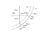
- FIG. 9 will explain how the correction dividing lines DL11c, DL12c, DL31c, DL32c, DL41c, DL42c, DL61c, and DL62c correct the connection angle by taking the correction dividing lines DL32c and DL62c as an example.
- the dividing line DL32 having no correction dividing line DL32c is connected to the hole processing line H1 at the connecting point P321 as shown by the broken line.
- the connection angle of the determination target at this time (connection angle before correction) is much smaller than 90 degrees.
- the correction dividing line DL32c is connected to the hole drilling line H1 at the connecting point P321c (second connecting point).
- connection angle (correction connection angle) on the same side as the connection angle of the determination target formed by the correction dividing line DL32c and the tangent line T321c of the hole processing line H1 at the connection point P321c is larger than the connection angle before correction.
- the corrected connection angle at the connection point P321c is preferably 90 degrees.
- the corrected connection angle must be at least greater than the pre-corrected connection angle.
- the correction connection angle is preferably 45 degrees or more. Even if the corrected connection angle is less than 90 degrees, it is not necessary to correct the corrected connection angle when it is equal to or more than a predetermined angle at which burning does not occur.
- the dividing line DL62 having no correction dividing line DL62c is connected to the hole drilling line H1 at the connecting point P621 (first connecting point) as shown by the broken line.
- the connection angle before correction at this time is much smaller than 90 degrees.
- the correction dividing line DL62c is connected to the hole drilling line H1 at the connecting point P621c (second connecting point).
- the correction connection angle formed by the correction dividing line DL62c and the tangent line T621c of the hole processing line H1 at the connection point P621c is larger than the connection angle before correction.
- the corrected connection angle at the connection point P621c is preferably 90 degrees.
- the corrected connection angle must be at least greater than the pre-corrected connection angle.
- the correction connection angle is preferably 45 degrees or more.
- the corrected connection angle may not be corrected.
- the correction dividing lines DL11c and DL12c, DL31c and DL32c, DL41c and DL42c, DL61c and DL62c are not limited to straight lines, and may be curves that are arcs, for example.
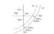
- FIG. 10 shows an example in which the correction dividing lines DL32ca and DL62ca composed of arcs are used instead of the straight correction dividing lines DL32c and DL62c in FIG. 9, respectively.
- the correction dividing lines DL32ca and DL62ca are connected to the drilling line H1 at the connecting points P321ca and P621ca, respectively.
- the correction connection angle when the correction dividing lines DL32ca and DL62ca are connected to the hole processing line H1 is larger than the connection angle before correction.
- the line segment between the auxiliary lines H1i, H2ai, H2b1 set in the hole forming region and the hole processing lines H1, H2a, H2b is straightened.
- the dividing line may be corrected so as to be replaced with a correction dividing line consisting of a curve.
- the correction dividing line is a straight line (line segment) or a curve from the position where the dividing line intersects the auxiliary lines H1i, H2ai, and H2b1 to the second connecting point different from the first connecting point.
- the part P2 is a part in which three holes having the same shape as each other are formed by cutting the hole processing lines H3a to H3c having the shapes as shown in the figure. If the outer shape of the part P2 is cut after the laser processing machine 100 forms three holes, the part P2 is cut out from the sheet metal W.
- the definitions of the X direction and the Y direction in FIG. 11 are the same as those in FIG.
- the laser machining machine 100 divides the hole forming region surrounded by the hole drilling lines H3a to H3c by the linear dividing lines DL8a, DL8b, and DL8c including the broken line portion, respectively. Then, the connection angle of the determination target is small at both the connection points P831b and P832b where the dividing line DL8b and the hole processing line H3b are connected. Further, the connection angle of the determination target is small at the connection point P832c where the dividing line DL8c and the hole processing line H3c are connected.
- a dividing line is set as shown in FIG. 11 to form a hole forming region.
- the machining program creating apparatus of one or more embodiments creates a machining program in which a dividing line for cutting the hole forming region is set as shown in FIG.
- virtual auxiliary lines H3ai to H3ci with the hole drilling lines H3a to H3c offset inward are set in the hole forming region in the hole drilling lines H3a to H3c, as shown by the alternate long and short dash line.
- the laser machining machine 100 cuts the hole forming region surrounded by the hole drilling lines H3b and H3c by the dividing lines DL8b'and DL8c'shown by solid lines, respectively.
- the dividing line DL8b' has a correction dividing line DL8b1c and DL8b2c between the auxiliary line H3bi and the drilling line H3b.
- the dividing line DL8c' has a correction dividing line DL8cc between the auxiliary line H3ci and the drilling line H3c.
- the dividing line DL8a for dividing the hole forming region surrounded by the hole processing line H3a does not need to be corrected and does not have a correction dividing line.
- the dividing line DL8b' is connected to the hole drilling line H3b at the connecting points P831bc and P832bc.
- the correction dividing lines DL8b1c and DL8b2c have a correction connection angle of 90 degrees at the connection points P831bc and P832bc.
- the dividing line DL8c' is connected to the hole drilling line H3c at the connecting point P832cc.
- the correction dividing line DL8cc has a correction connection angle of 90 degrees at the connection point P832cc.
- the shape of the auxiliary lines H3ai to H3ci may be similar to the shape of the drilling lines H3a to H3c, but it does not have to be similar.
- the auxiliary lines H3ai to H3ci may be set at positions separated from the drilling lines H3a to H3c by a predetermined distance inward.
- the predetermined distance may be a constant distance, but it does not have to be a constant distance.
- the laser machining machine 100 cuts the dividing line DL8a from the pierced earrings Ps8a to, for example, the connecting point P831a in the hole forming region surrounded by the hole drilling line H3a, and subsequently, the connecting point in the reverse direction from the piercing line Ps8a.
- the dividing line DL8a is cut up to P832a.
- the laser machining machine 100 cuts the dividing line DL8b'from the pierced earrings Ps8b until it reaches the auxiliary line H3bi, and then cuts the correction dividing line DL8b1c up to the connecting point P831bc.
- the laser machine 100 cuts the dividing line DL8b'from the pierced earrings Ps8b until it reaches the auxiliary line H3bi in the opposite direction, and then cuts the correction dividing line DL8b2c up to the connection point P832bc.
- the laser machining machine 100 cuts the dividing line DL8c'from the pierced earrings Ps8c to, for example, the connection point P831c in the hole forming region surrounded by the drilling line H3c. Subsequently, the laser machine 100 cuts the dividing line DL8c'from the pierced earrings Ps8c until it reaches the auxiliary line H3ci in the opposite direction, and then cuts the correction dividing line DL8cc up to the connection point P832cc.
- FIG. 12 shows a case where two hole processing lines H41 and H42 parallel to each other are at a short distance.
- the auxiliary lines H41i and H42i offset from the hole drilling lines H41 and H42, respectively, may be located outside the hole forming region surrounded by the hole drilling lines H41 and H42.
- the dividing line DL9 shown by the broken line does not intersect with the auxiliary lines H41i and H42i, and the correction dividing line can be set by the same method as in FIGS. 7 and 11. Can not.
- the correction dividing line DL9c is set as shown in FIG. 12 to cut the hole forming region.
- the machining program creating apparatus of one or more embodiments creates a machining program in which a correction dividing line for cutting the hole forming region is set as shown in FIG.
- the laser machining machine 100 cuts the hole forming region at the correction dividing line DL9c orthogonal to the hole drilling lines H41 and H42 shown by the solid line.
- the laser machining machine 100 cuts the correction dividing line DL9c from the pierced line Ps9 formed between the hole drilling lines H41 and H42 until it reaches, for example, the hole drilling line H41, and subsequently reaches the hole drilling line H42 from the pierced line Hs9.
- the correction dividing line DL9c is cut up to.
- the CAM device 2 reads the CAD data including the graphic data of the parts in step S1.
- the CAM device 2 determines whether or not there is an unallocated hole to which the cutting path has not been assigned. If there is no unallocated hole (NO), the CAM device 2 allocates a cutting path to the outer shape of the part in step S3, and ends the process.
- step S2 determines in step S11 whether or not the unallocated hole is a hole of a size to be divided. If the unallocated hole is not a hole of a size to be divided (NO), the CAM device 2 allocates a cutting path around the hole (hole forming region) (hole processing line) in step S12 and processes the hole. Is returned to step S2.
- the CAM device 2 sets a dividing line in the hole forming region in step S13. Specifically, the CAM device 2 sets one or more dividing lines along the X or Y direction, depending on the size of the holes and the maximum size of the scrap. The CAM device 2 sets an auxiliary line in the hole forming region in step S14, and corrects the dividing line in step S15 as described with reference to FIG. 7 or FIG.
- the CAM device 2 determines in step S16 whether or not the connection angle between the dividing line and the drilled line has been improved. Of the two connection angles that sandwich the dividing line, if the connection angle on the same side as the connection angle to be determined before correction is
- connection angle is not improved in step S16 (NO)
- the CAM device 2 deletes the correction of the dividing line in step S18.
- step S19 the CAM apparatus 2 allocates a cutting path for the dividing line in the hole forming region, allocates a cutting path for forming a hole around the hole forming region, and returns the process to step S2. ..
- FIG. 14 shows a functional configuration example of the CAM device 2 that generates a machining program.
- the CAM device 2 has a functional configuration as shown in FIG. 21 by executing CAM software (computer program).
- the sheet metal setting unit 201 executes sheet metal based on the graphic data of the part to be manufactured (hereinafter, part graphic data) and the graphic data of the sheet metal W (hereinafter, sheet metal graphic data), and the sheet metal information. To generate.
- the sheet metal setting unit 201 executes itatori so as to arrange the number of parts indicated by the instruction signal instructed by operating the operation unit (not shown) in the figure indicating the sheet metal W.
- the part graphic data and the sheet metal graphic data may be supplied from the CAD device 1 to the CAM device 2, or may be read from the database 3 and supplied to the CAM device 2.
- the hole division necessity determination unit 202 determines whether or not the hole needs to be divided by the dividing line when the part to be manufactured has a hole based on the part graphic data.
- the dividing line setting unit 203 sets one or a plurality of dividing lines in the hole forming region based on the part graphic data.
- the dividing line correction necessity determination unit 204 determines whether or not the connection angle when the dividing line is connected to the drilled line is small and it is necessary to correct the dividing line in order to increase the connection angle. judge.
- the dividing line correction unit 205 sets the correction dividing line based on the part graphic data and corrects the dividing line.
- the correction possibility determination unit 206 determines whether or not the connection angle is actually improved by the division line corrected by the division line correction unit 205 based on the part graphic data. As described above, the correction possibility determination unit 206 determines whether or not the relationship of
- the correction possibility determination unit 206 instructs the dividing line correction unit 205 to delete the correction of the dividing line.
- the dividing line correction unit 205 deletes the correction of the dividing line and returns to the original dividing line set by the dividing line setting unit 203.
- the correctability determination unit 206 may not be provided, but it is preferable to provide it.
- the cutting path setting unit 207 sets the dividing line in the hole forming region based on the part graphic data and the dividing line finally set by the dividing line correction unit 205. Allocate a cutting path and allocate a cutting path to form a hole around the hole forming area. When the hole does not need to be divided by the dividing line, the cutting path setting unit 207 allocates only the cutting path for forming the hole around the hole forming region.
- the flowchart shown in FIG. 13 shows the processes executed by the above-mentioned hole division necessity determination unit 202 to the cutting route setting unit 207.
- the NC data creation unit 208 is a laser processing machine 100 so that the NC device 50 cuts the sheet metal W to produce one or a plurality of parts based on the sheet metal cutting information and the cutting path set by the cutting route setting unit 207. Create NC data to control.
- the NC data is a machining program configured by a machine control code for the NC device 50 to control the laser machining machine 100.
- the present invention is not limited to one or more embodiments described above, and various modifications can be made without departing from the gist of the present invention.
- the hole forming region is cut along a dividing line parallel to the X or Y direction set in the hole forming region, and the hole forming region is divided into a plurality of scraps.
- how to divide the hole forming region is not limited.
- the method of arranging the skids 13 or the configuration of the skids 13 is not limited to the configuration example shown in FIG.
Landscapes
- Engineering & Computer Science (AREA)
- Physics & Mathematics (AREA)
- Optics & Photonics (AREA)
- Mechanical Engineering (AREA)
- Plasma & Fusion (AREA)
- Robotics (AREA)
- Laser Beam Processing (AREA)
Priority Applications (2)
| Application Number | Priority Date | Filing Date | Title |
|---|---|---|---|
| US18/036,278 US20230398637A1 (en) | 2020-11-27 | 2021-11-16 | Laser processing method, laser processing machine, and processing program creation device |
| EP21897807.0A EP4252956B1 (en) | 2020-11-27 | 2021-11-16 | Laser processing method, laser processing device, and processing program creation device |
Applications Claiming Priority (2)
| Application Number | Priority Date | Filing Date | Title |
|---|---|---|---|
| JP2020-196669 | 2020-11-27 | ||
| JP2020196669A JP7503483B2 (ja) | 2020-11-27 | 2020-11-27 | レーザ加工方法、レーザ加工機、及び加工プログラム作成装置 |
Publications (1)
| Publication Number | Publication Date |
|---|---|
| WO2022113833A1 true WO2022113833A1 (ja) | 2022-06-02 |
Family
ID=81755946
Family Applications (1)
| Application Number | Title | Priority Date | Filing Date |
|---|---|---|---|
| PCT/JP2021/042121 Ceased WO2022113833A1 (ja) | 2020-11-27 | 2021-11-16 | レーザ加工方法、レーザ加工機、及び加工プログラム作成装置 |
Country Status (4)
| Country | Link |
|---|---|
| US (1) | US20230398637A1 (cg-RX-API-DMAC7.html) |
| EP (1) | EP4252956B1 (cg-RX-API-DMAC7.html) |
| JP (1) | JP7503483B2 (cg-RX-API-DMAC7.html) |
| WO (1) | WO2022113833A1 (cg-RX-API-DMAC7.html) |
Families Citing this family (1)
| Publication number | Priority date | Publication date | Assignee | Title |
|---|---|---|---|---|
| DE102021116899A1 (de) * | 2021-06-30 | 2023-01-05 | Messer Cutting Systems Gmbh | Verfahren zur thermischen Bearbeitung eines Werkstücks mit einer thermischen Bearbeitungsmaschine |
Citations (6)
| Publication number | Priority date | Publication date | Assignee | Title |
|---|---|---|---|---|
| JPH10244394A (ja) * | 1997-03-03 | 1998-09-14 | Amada Co Ltd | レーザ加工機におけるスクラップ排出方法およびその装置 |
| JP2000141165A (ja) * | 1998-11-09 | 2000-05-23 | Amutekku:Kk | 端材分割方法、その装置並びに端材分割方法のプログラムを記憶した記録媒体 |
| JP2015100828A (ja) | 2013-11-27 | 2015-06-04 | 株式会社アマダ | レーザ切断加工方法及び装置並びに自動プログラミング装置 |
| JP2016078063A (ja) | 2014-10-15 | 2016-05-16 | 株式会社アマダホールディングス | レーザ加工機、レーザ加工方法、加工データ作成装置 |
| WO2019188694A1 (ja) * | 2018-03-28 | 2019-10-03 | 株式会社アマダホールディングス | レーザ加工機、レーザ加工方法、及び加工プログラム作成装置 |
| JP2020196669A (ja) | 2019-05-31 | 2020-12-10 | 小林製薬株式会社 | ビタミンb12類の光安定化方法 |
Family Cites Families (2)
| Publication number | Priority date | Publication date | Assignee | Title |
|---|---|---|---|---|
| WO2012136262A1 (en) | 2011-04-07 | 2012-10-11 | Tomologic Ab | Method of, system and computer program for machine cutting several parts of a piece of material using controlling rules and variables for cutting |
| JP7514742B2 (ja) | 2020-11-19 | 2024-07-11 | 株式会社アマダ | レーザ加工方法、レーザ加工機、及び加工プログラム作成装置 |
-
2020
- 2020-11-27 JP JP2020196669A patent/JP7503483B2/ja active Active
-
2021
- 2021-11-16 WO PCT/JP2021/042121 patent/WO2022113833A1/ja not_active Ceased
- 2021-11-16 US US18/036,278 patent/US20230398637A1/en active Pending
- 2021-11-16 EP EP21897807.0A patent/EP4252956B1/en active Active
Patent Citations (6)
| Publication number | Priority date | Publication date | Assignee | Title |
|---|---|---|---|---|
| JPH10244394A (ja) * | 1997-03-03 | 1998-09-14 | Amada Co Ltd | レーザ加工機におけるスクラップ排出方法およびその装置 |
| JP2000141165A (ja) * | 1998-11-09 | 2000-05-23 | Amutekku:Kk | 端材分割方法、その装置並びに端材分割方法のプログラムを記憶した記録媒体 |
| JP2015100828A (ja) | 2013-11-27 | 2015-06-04 | 株式会社アマダ | レーザ切断加工方法及び装置並びに自動プログラミング装置 |
| JP2016078063A (ja) | 2014-10-15 | 2016-05-16 | 株式会社アマダホールディングス | レーザ加工機、レーザ加工方法、加工データ作成装置 |
| WO2019188694A1 (ja) * | 2018-03-28 | 2019-10-03 | 株式会社アマダホールディングス | レーザ加工機、レーザ加工方法、及び加工プログラム作成装置 |
| JP2020196669A (ja) | 2019-05-31 | 2020-12-10 | 小林製薬株式会社 | ビタミンb12類の光安定化方法 |
Non-Patent Citations (1)
| Title |
|---|
| See also references of EP4252956A4 |
Also Published As
| Publication number | Publication date |
|---|---|
| JP2022085150A (ja) | 2022-06-08 |
| JP7503483B2 (ja) | 2024-06-20 |
| EP4252956B1 (en) | 2025-03-19 |
| US20230398637A1 (en) | 2023-12-14 |
| EP4252956A4 (en) | 2024-06-26 |
| EP4252956A1 (en) | 2023-10-04 |
Similar Documents
| Publication | Publication Date | Title |
|---|---|---|
| JP4954220B2 (ja) | 部品集合体の切断方法 | |
| JP5828953B2 (ja) | カッティングするための制御ルールおよび変数を使用して1つの材料からいくつかの部材をマシンカッティングするための方法、システムおよびコンピュータプログラム | |
| KR20190094169A (ko) | 가요성 시트 재료에서 커팅되도록 의도된 파트들의 미리 결정된 배치를 분할하기 위한 방법 | |
| EP3778104B1 (en) | Laser processing machine, laser processing method, and processing program generation device | |
| JP2022085150A (ja) | レーザ加工方法、レーザ加工機、及び加工プログラム作成装置 | |
| US20230405727A1 (en) | Laser processing method, laser processing machine, and processing program creation device | |
| JP6712612B2 (ja) | 割付データ作成装置及び割付データ作成方法 | |
| US12370627B2 (en) | Laser machining apparatus, laser machining method, and processing program creation device | |
| WO2022168717A1 (ja) | レーザ加工方法、加工プログラム作成方法、及びレーザ加工機 | |
| US20250196271A1 (en) | Laser processing path laying-out method, laser processing method, and laser processing path laying-out device | |
| KR101548662B1 (ko) | 부재정보 배치영역 선정 시스템 및 방법 | |
| JP7165489B2 (ja) | シート上にパーツを編集配置する加工プログラムの作成装置及び方法 | |
| JP4427927B2 (ja) | 自動板取り装置及び自動板取り方法 | |
| JP2015057295A (ja) | カッティングのための制御ルールおよび変数 | |
| JP6160815B2 (ja) | レーザ加工方法およびレーザ加工システム | |
| JP5961100B2 (ja) | 材料に対して複数の面に跨る穴またはノッチを形成する際の加工範囲及び加工順を決定する決定方法及び決定プログラム | |
| JP2004118617A (ja) | 加工図形分類方法及びその装置、加工処理方法及びそのシステム並びにプログラム | |
| JPH11192572A (ja) | レーザ加工機におけるピアス加工方法およびピアス加工開始位置制御装置 | |
| WO2022168724A1 (ja) | レーザ加工方法、加工プログラム作成方法、及びレーザ加工機 | |
| JP2022101118A (ja) | 情報処理装置、順序決定方法、及び順序決定プログラム | |
| JPH05313724A (ja) | 切断加工データ作成装置 |
Legal Events
| Date | Code | Title | Description |
|---|---|---|---|
| 121 | Ep: the epo has been informed by wipo that ep was designated in this application |
Ref document number: 21897807 Country of ref document: EP Kind code of ref document: A1 |
|
| NENP | Non-entry into the national phase |
Ref country code: DE |
|
| ENP | Entry into the national phase |
Ref document number: 2021897807 Country of ref document: EP Effective date: 20230627 |