WO2022113690A1 - ダクトシステム、ダクト、ダクト固定具、固定部材及び什器 - Google Patents
ダクトシステム、ダクト、ダクト固定具、固定部材及び什器 Download PDFInfo
- Publication number
- WO2022113690A1 WO2022113690A1 PCT/JP2021/040709 JP2021040709W WO2022113690A1 WO 2022113690 A1 WO2022113690 A1 WO 2022113690A1 JP 2021040709 W JP2021040709 W JP 2021040709W WO 2022113690 A1 WO2022113690 A1 WO 2022113690A1
- Authority
- WO
- WIPO (PCT)
- Prior art keywords
- duct
- rail
- fixing portion
- fixture
- adapter
- Prior art date
- Legal status (The legal status is an assumption and is not a legal conclusion. Google has not performed a legal analysis and makes no representation as to the accuracy of the status listed.)
- Ceased
Links
Images


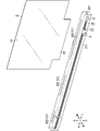


Classifications
-
- A—HUMAN NECESSITIES
- A47—FURNITURE; DOMESTIC ARTICLES OR APPLIANCES; COFFEE MILLS; SPICE MILLS; SUCTION CLEANERS IN GENERAL
- A47B—TABLES; DESKS; OFFICE FURNITURE; CABINETS; DRAWERS; GENERAL DETAILS OF FURNITURE
- A47B13/00—Details of tables or desks
-
- A—HUMAN NECESSITIES
- A47—FURNITURE; DOMESTIC ARTICLES OR APPLIANCES; COFFEE MILLS; SPICE MILLS; SUCTION CLEANERS IN GENERAL
- A47B—TABLES; DESKS; OFFICE FURNITURE; CABINETS; DRAWERS; GENERAL DETAILS OF FURNITURE
- A47B97/00—Furniture or accessories for furniture, not provided for in other groups of this subclass
-
- H—ELECTRICITY
- H01—ELECTRIC ELEMENTS
- H01R—ELECTRICALLY-CONDUCTIVE CONNECTIONS; STRUCTURAL ASSOCIATIONS OF A PLURALITY OF MUTUALLY-INSULATED ELECTRICAL CONNECTING ELEMENTS; COUPLING DEVICES; CURRENT COLLECTORS
- H01R25/00—Coupling parts adapted for simultaneous co-operation with two or more identical counterparts, e.g. for distributing energy to two or more circuits
- H01R25/14—Rails or bus-bars constructed so that the counterparts can be connected thereto at any point along their length
-
- H—ELECTRICITY
- H01—ELECTRIC ELEMENTS
- H01R—ELECTRICALLY-CONDUCTIVE CONNECTIONS; STRUCTURAL ASSOCIATIONS OF A PLURALITY OF MUTUALLY-INSULATED ELECTRICAL CONNECTING ELEMENTS; COUPLING DEVICES; CURRENT COLLECTORS
- H01R41/00—Non-rotary current collectors for maintaining contact between moving and stationary parts of an electric circuit
Definitions
- This disclosure generally relates to duct systems, ducts, duct fixtures, fixing members and fixtures. More specifically, the present disclosure relates to a duct system fixed to a fixture, a duct used in this duct system, a duct fixative, a fixing member and a fixture.
- Patent Document 1 discloses a configuration in which an OA tap (power tap) is attached to a table (furniture) and a plurality of cables are connected to the OA tap. As a result, the electric device placed on the table can be connected to the power source to supply electric power to the electric device.
- OA tap power tap
- the duct system includes a duct and a duct fixture.
- the duct has a duct rail and a conductive bar.
- the conductive bar is housed in the duct rail. Electric power is supplied to the conductive bar.
- the duct can electrically connect the adapter at any position in the mounting area continuous in the length direction of the duct rail, and supplies electric power to the electric device through the adapter.
- the adapter receives the electric power from the conductive bar.
- the duct fixative has a first fixing portion to which the duct is fixed and a second fixing portion to be fixed to the fixture.
- the duct according to one aspect of the present disclosure is used for the duct system.
- the duct fixture according to one aspect of the present disclosure is used for the duct system.
- the fixing member according to one aspect of the present disclosure is used as the second fixing portion in the duct system.
- the fixture according to one aspect of the present disclosure is provided with a duct fixture for fixing the duct.
- the duct has a duct rail and a conductive bar.
- the conductive bar is housed in the duct rail. Electric power is supplied to the conductive bar.
- the duct can electrically connect the adapter at any position in the mounting area continuous in the length direction of the duct rail, and supplies electric power to the electric device through the adapter.
- the adapter receives the electric power from the conductive bar.
- FIG. 1 is a perspective view of the duct system according to the first embodiment.
- FIG. 2 is a front view of the same duct system.
- FIG. 3 is a right side view of the duct system of the same as above.
- FIG. 4 is a plan view of the duct system of the same as above.
- FIG. 5 is a bottom view of the duct system of the same.
- FIG. 6 is an exploded perspective view of the duct system of the same as above.
- FIG. 7 is an exploded perspective view of a main part of the duct system as above.
- FIG. 8 is an exploded perspective view of a main part of the duct system as above.
- 9A and 9B are cross-sectional views of the same duct system corresponding to the IX-IX cross section in FIG. FIG.
- FIG. 10 is a cross-sectional view of the same duct system corresponding to the XX cross section in FIG.
- FIG. 11 is a plan view of the same duct system with the two adapters attached.
- FIG. 12 is an explanatory diagram of a procedure for attaching an adapter to the duct system of the same.
- FIG. 13 is an explanatory diagram of a procedure for attaching an adapter to the duct system of the same.
- FIG. 14 is a side sectional view of the duct system and the adapter as above.
- FIG. 15 is a block diagram showing a configuration example of a system for supplying power to a plurality of electric devices using the duct system of the same.
- FIG. 16 is a perspective view of the duct according to the second embodiment.
- FIG. 17 is a front sectional view of the duct system according to the third embodiment.
- FIG. 18 is a perspective view of the desk (furniture) according to the fourth embodiment.
- FIG. 19 is a front view of the desk as above.
- FIG. 20 is a rear view of the desk as above.
- FIG. 21 is a right side view of the desk as above.
- FIG. 22 is a plan view of the desk as above.
- FIG. 23 is a bottom view of the desk as above.
- each of the following embodiments is only part of the various embodiments of the present disclosure.
- Each of the following embodiments can be variously modified according to the design and the like as long as the object of the present disclosure can be achieved.
- each figure described in each of the following embodiments is a schematic view, and the ratio of the size and the thickness of each component in the figure does not necessarily reflect the actual dimensional ratio. do not have.
- each of the following embodiments may be realized by appropriately combining them.
- the "duct” is also referred to as a “DC duct” and the “duct system” is referred to as “duct system” in order to explain the case where the electric power supplied from the duct to the adapter is DC (direct current) electric power as an example. Also called “DC duct system”.
- the electric power supplied from the duct to the adapter is not limited to DC electric power, and may be AC (alternating current) electric power.
- FIG. 1 is a perspective view of the DC duct system 100.
- FIG. 2 is a front view of the DC duct system 100. Since the rear view of the DC duct system 100 is symmetrical with the front view, the illustration is omitted.
- FIG. 3 is a right side view of the DC duct system 100. Since the left side view of the DC duct system 100 matches the right side view, the illustration is omitted.
- FIG. 4 is a plan view of the DC duct system 100.
- FIG. 5 is a bottom view of the DC duct system 100.
- the DC duct system 100 of the present embodiment includes a DC duct 3 and a duct fixture F1.
- the DC duct 3 has a duct rail 31 and a conductive bar 32 (see FIG. 8).
- the conductive bar 32 is housed in the duct rail 31. Electric power is supplied to the conductive bar 32.
- the DC duct 3 can electrically connect the adapter 5 (see FIG. 13) at any position in the mounting area continuous in the length direction of the duct rail 31, and powers the electric device 94 via the adapter 5. Supply.
- the adapter 5 receives electric power from the conductive bar 32.
- the duct fixture F1 has a first fixing portion 1 to which the DC duct 3 is fixed, and a second fixing portion 2 to be fixed to the fixture (desk 7).
- the DC duct 3 can be fixed to the fixture via the duct fixture F1. Then, by connecting the electric device 94 (or the cable connected to the electric device 94) to the adapter 5, electric power can be supplied from the DC duct 3 to the electric device 94. Therefore, as compared with the case where the electric power is supplied to the electric device 94 from the power outlet or from the power tap that distributes the electric power of the power outlet, it is possible to improve the wiring arrangement around the fixture. That is, the state around the fixtures is less likely to be messy, such as the wiring of the electrical equipment 94 being mixed, and the surroundings of the fixtures can be made neat.
- a connector 95 (see FIG. 15) that receives DC power may be connectable to the adapter 5.
- the conductive bar 32 may supply DC (direct current) power to the connector 95 via the adapter 5.
- the mounting area is an area provided on at least one of the surface and the inside of the duct rail 31.
- the DC duct 3 of the present embodiment includes a recess 3110 (see FIGS. 8 and 13) formed along the length direction of the duct rail 31. That is, the recesses 3110 are continuous in the length direction. In other words, the recess 3110 is one recess continuous in the length direction. More specifically, the recess 3110 is formed over both ends of the duct rail 31 in the length direction.
- the mounting area coincides with the area where the recess 3110 is provided.
- the type of electrical equipment 94 is not particularly limited.
- a computer terminal personal computer, smartphone, tablet terminal, etc.
- an accessory device of the computer terminal monitoring, speaker, microphone, etc.
- a lighting device desk light, etc.
- a network camera a sensor (temperature sensor, etc.) , Humidity sensor, illuminance sensor, etc.), game machines and air conditioning equipment (desktop fans, etc.).
- the DC duct system 100 is used by being fixed to furniture, for example.
- Fixtures are a general term for furniture and fixtures used in residential or non-residential homes.
- An example of furniture is a desk, table, workbench, etc. used as a table on which objects are placed.
- Another example of furniture is shelves, boxes, dressers, beds, whiteboards, screens, dividers and chaise lounges.
- the desk 7 of the present embodiment has a top plate 71 having a rectangular shape in a plan view, two legs 72, and two support bases 73.
- the direction along the long side of the top plate 71 is defined as the left-right direction
- the direction along the short side of the top plate 71 is defined as the front-back direction
- the direction along the normal line of the top plate 71 is defined. It is defined as the vertical direction.
- these provisions do not mean to limit the direction of use of the DC duct system 100.
- the arrows indicating front-back, left-right, and up-down in FIG. 1 and the like are shown for the sake of explanation, and are not accompanied by an entity.
- the DC duct system 100 includes a partition fixing structure S1 capable of fixing the partition 6.
- a "partition” is also referred to as a partition or tsuitate.
- the ducted duct system 200 includes a DC duct system 100 and a partition 6. In the present embodiment, the number of partitions 6 included in the duct system 200 with partitions is three.
- the partition 6 is fixed above the top plate 71.
- the space above the top plate 71 is divided into a space on the front side and a space on the rear side.
- Some people hereinafter referred to as "first person”
- second person Some others
- the DC duct system 100 includes a duct fixture F1, two DC ducts 3 (only one is shown in FIG. 1), and two feed-ins (only one is shown in FIG. 1). It comprises 4 (feed-in cap) (see FIG. 7) and two end caps E1 (only one is shown in FIG. 7).
- the duct fixative F1 has two first fixing portions 1 and two second fixing portions 2.
- the two first fixing portions 1 have a one-to-one correspondence with the two DC ducts 3.
- Each first fixing portion 1 holds a corresponding DC duct 3. That is, each DC duct 3 is fixed to the corresponding first fixing portion 1.
- the two second fixing portions 2 are fixed to the fixture (desk 7).
- the desk 7 has a top plate 71 having a rectangular shape in a plan view, two legs 72, and two support bases 73.
- One of the two legs 72 projects downward from the vicinity of the right end of the top plate 71, and the other projects downward from the vicinity of the left end of the top plate 71.
- the two support bases 73 correspond one-to-one with the two legs 72.
- Each support base 73 is connected to the lower end of the corresponding leg portion 72 and supports the leg portion 72.
- each of the two first fixing portions 1 includes a duct accommodating portion 11 and two connecting protrusions 12.
- the duct accommodating portion 11 and the two connecting protrusions 12 are integrally formed.
- the shape of the duct storage portion 11 is a rectangular parallelepiped shape.
- the duct accommodating portion 11 has a length in the left-right direction.
- One of the two connecting protrusions 12 protrudes from the right end of the duct storage portion 11, and the other protrudes from the left end of the duct storage portion 11.
- the duct accommodating portion 11 accommodates the DC duct 3 (and the duct rail 31 of the DC duct 3).
- the duct storage unit 11 also stores the feed-in 4.
- Each of the two connecting protrusions 12 is configured to connect the first fixing portion 1 to the second fixing portion 2.
- Each first fixing portion 1 has a storage groove 130 and two through grooves 140.
- the storage groove 130 stores the DC duct 3 and the feed-in 4.
- Wiring W1 (see FIGS. 9A and 9B) electrically connected to the DC duct 3 is passed through the wire groove 140.
- the storage groove 130 is provided in the duct storage portion 11.
- the storage groove 130 is formed along the length direction (left-right direction) of the duct storage portion 11. That is, the storage groove 130 is continuous in the length direction.
- the storage groove 130 is open in the front surface of the duct storage portion 11, and in the first fixing portion 1 on the rear side, the storage groove 130 is It is open on the rear surface of the duct storage portion 11.
- the two wiring grooves 140 correspond one-to-one with the two connecting protrusions 12.
- Each wire groove 140 is provided over the corresponding connecting protrusion 12 and the duct accommodating portion 11. That is, through grooves 140 are provided at the right end and the left end of the first fixing portion 1, respectively.
- Each wire groove 140 is formed along the length direction (left-right direction) of the duct accommodating portion 11. That is, each through groove 140 is continuous in the above-mentioned length direction.
- each through groove 140 is open on the rear surface of the duct accommodating portion 11, and in the rear first fixing portion 1, each passing wire is connected.
- the groove 140 is open on the front surface of the duct accommodating portion 11.
- each wire groove 140 is connected to a storage groove 130.
- the wiring W1 passed through the wire groove 140 is electrically connected to the terminal portion 432 (see FIGS. 9A and 9B) of the feed-in 4 housed in the storage groove 130, and is connected to the DC duct via the terminal portion 432. 3 is electrically connected to the conductive bar 32 (see FIGS. 8 and 9A).
- Each of the two first fixing portions 1 has a part of the partition fixing structure S1. That is, each of the two first fixing portions 1 has four recesses 150 (only two are shown in FIG. 7). The four recesses 150 are provided in the duct storage portion 11. Of the two first fixing portions 1, in the front first fixing portion 1, each recess 150 is provided on the rear surface of the duct accommodating portion 11, and in the rear first fixing portion 1, each recess 150 is provided. It is provided on the front surface of the duct storage portion 11. Each recess 150 is provided from the upper end to the lower end of the duct accommodating portion 11.
- each partition fixing structure S1 is a through hole that penetrates the configuration in which the two first fixing portions 1 are combined in the vertical direction.
- the four partition fixing structures S1 are arranged in the left-right direction.
- the four partition fixing structures S1 have a one-to-one correspondence with the four fitting projections 62 (see FIG. 6) belonging to the three partitions 6.
- a corresponding fitting projection 62 is inserted into each partition fixing structure S1.
- each partition 6 is fixed to the two first fixing portions 1.
- each of the two second fixing portions 2 includes a horizontal portion 21, a strut portion 22, and a clamp mechanism 23.
- the horizontal portion 21 and the support portion 22 are integrally formed.
- the two second fixing portions 2 are configurations (fixing members) for fixing the duct rail 31 to the fixture (desk 7). More specifically, the two second fixing portions 2 are used together with the two first fixing portions 1 to fix the duct rail 31 to the fixture (desk 7).
- the shape of the horizontal portion 21 is a square cylinder.
- the axial direction of the horizontal portion 21 is along the left-right direction.
- the two second fixing portions 2 correspond one-to-one with the two connecting protrusions 12 of each of the two first fixing portions 1.
- the corresponding connecting projections 12 of the two first fixing portions 1 are inserted into the horizontal portion 21 of each second fixing portion 2. Further, the two first fixing portions 1 are screwed to the two second fixing portions 2, respectively.
- the two first fixing portions 1 are connected to the two second fixing portions 2. That is, the two first fixing portions 1 are connected to the two second fixing portions 2 so as to bridge between the two second fixing portions 2.
- each of the two first fixing portions 1 is separable from the two second fixing portions 2. That is, by removing the screw connecting the two first fixing portions 1 and the two second fixing portions 2 and pulling out each connecting projection 12 from the horizontal portion 21, each of the two first fixing portions 1 is 2 It can be separated from the two second fixing portions 2.
- the shape of the support column 22 is cylindrical.
- the axial direction of the support column 22 is along the vertical direction.
- the horizontal portion 21 projects in the left-right direction from the upper end of the support column portion 22.
- the internal space of the horizontal portion 21 is connected to the internal space of the column portion 22 to form one internal space SP1.
- Wiring W1 (see FIG. 9A) is passed through the internal space SP1. That is, the second fixing portion 2 (fixing member) has an internal space SP1 through which the wiring W1 electrically connected to the conductive bar 32 (see FIG. 8) is passed.
- the strut portion 22 has a wire hole 220.
- the wire hole 220 is provided on the side surface of the support column 22.
- the wiring W1 is drawn out from the internal space SP1 through the wire hole 220.
- the clamp mechanism 23 is fixed to the desk 7 (furniture) by sandwiching the desk 7 (furniture). More specifically, the clamp mechanism 23 of the second fixing portion 2 of the two second fixing portions 2 sandwiches the left end of the top plate 71 of the desk 7, and the clamping mechanism 23 of the other second fixing portion 2 is , Clamp the right end of the top plate 71. As a result, the DC duct system 100 is fixed to the desk 7 (furniture).
- the clamp mechanism 23 has a movable portion 231, a base 232, and an operation portion 233.
- the base 232 is integrally formed with the support column 22.
- the base 232 projects in the left-right direction from the lower end of the support column 22.
- the movable portion 231 is arranged on the base 232. A part of the movable portion 231 is arranged inside the through hole 220 of the support column portion 22.
- the operation unit 233 accepts an operation for moving the movable unit 231 up and down.
- the operation unit 233 is a lever, and the movable unit 231 moves up and down when the operator turns the operation unit 233.
- a procedure for fixing the DC duct system 100 to the desk 7 using the clamp mechanism 23 will be described.
- a part (left end or right end) of the top plate 71 of the desk 7 is inserted into the wire hole 220.
- a part (left end or right end) of the top plate 71 is arranged between the support column portion 22 and the movable portion 231.
- the operator turns the operation unit 233 to move the movable unit 231 upward.
- a part (left end or right end) of the top plate 71 is sandwiched between the support column portion 22 and the movable portion 231.
- the DC duct system 100 is fixed to the desk 7 by sandwiching the left end and the right end of the top plate 71 by using the respective clamp mechanisms 23 of the two second fixing portions 2.
- the second fixing portion 2 (fixing member) includes a strut portion 22 that supports the two duct rails 31 with a gap G1 between the two duct rails 31 and the desk 7 (furniture).
- the fact that there is a gap between the duct rail 31 and the desk 7 (furniture) means that a predetermined member (a part of the first fixing portion 1) is between the duct rail 31 and the desk 7 as in the present embodiment. ), And there is a gap G1 extending from the lower surface of the predetermined member to the upper surface of the desk 7. Further, in the present disclosure, the gap between the duct rail 31 and the desk 7 (furniture) includes a case where there is a gap extending from the lower surface of the duct rail 31 to the upper surface of the desk 7.
- an opening may be provided in a portion of the top plate 71 of the desk 7 below the first fixing portion 1.
- the opening is configured to draw out the wiring for supplying AC power from under the top plate 71. The user can reach into the gap G1 and pull out the wiring through the opening.
- each of the two DC ducts 3 has a duct rail 31 and two conductive bars 32.
- the duct rail 31 includes a first rail 311 and two second rails 312.
- the two DC ducts 3 correspond one-to-one with the two first fixing portions 1.
- Each DC duct 3 is housed in the storage groove 130 of the corresponding first fixing portion 1. Therefore, one of the two DC ducts 3 is arranged on the front side with respect to the partition 6, and the other is arranged on the rear side with respect to the partition 6. That is, the DC duct system 100 includes a plurality (two) of DC ducts 3, and the plurality of DC ducts 3 include two DC ducts 3 arranged on both sides of the partition 6 in the thickness direction.
- a predetermined number of DC ducts 3 are fixed along the horizontal plane with a plurality of DC ducts 3 fixed to the first fixing portion 1 and the second fixing portion 2 fixed to the fixture (desk 7). They are located on opposite sides of each other in the direction (front-back direction). In other words, the above two DC ducts 3 are arranged side by side.
- the shape of the first rail 311 is a square cylinder.
- the first rail 311 is made of metal, for example.
- the axial direction (length direction) of the first rail 311 is along the left-right direction.
- the first rail 311 includes a recess 3110.
- the recess 3110 is formed along the length direction (left-right direction) of the duct rail 31. More specifically, the recess 3110 is formed over both ends of the duct rail 31 in the length direction.
- Two conductive bars 32 are housed in the recess 3110.
- the recess 3110 forms an opening in the duct rail 31 that opens along the direction orthogonal to the surface of the partition 6.
- the recess 3110 forms an opening in the surface along the surface of the partition 6. More specifically, in the DC duct 3 on the front side of the two DC ducts 3, an opening is formed in the front surface of the first rail 311 by the recess 3110 as shown in FIG. In the DC duct 3 on the rear side, as shown in FIG. 8, an opening is formed on the rear surface of the first rail 311 by the recess 3110. Each opening is continuous in the left-right direction.
- the surface (front or rear surface) along the vertical direction is provided by the recess 3110.
- an opening is formed in the duct rail 31.
- the recess 3110 forms an opening on the opposite surface to the recess 3110 of the other DC duct 3.
- the first rail 311 further includes two fitting portions 3111 and two mounting grooves 3112.
- Each of the two fitting portions 3111 is a groove.
- the two fitting portions 3111 are provided on the inner surface of the recess 3110.
- the two fitting portions 3111 are formed along the length direction (left-right direction) of the duct rail 31. That is, each fitting portion 3111 is continuous in the length direction. More specifically, the two fitting portions 3111 are formed over both ends of the duct rail 31 in the length direction.
- the two fitting portions 3111 are fitted to the adapter 5.
- the adapter 5 is attached to the DC duct 3.
- the duct rail 31 includes an adapter mounting portion (two fitting portions 3111) for mounting the adapter 5. The procedure for attaching the adapter 5 to the DC duct 3 will be described later.
- the two mounting grooves 3112 are provided on the inner surface of the recess 3110. Of the two fitting portions 3111 and the two mounting grooves 3112, the two fitting portions 3111 are provided closer to the opening of the recess 3110.
- the two mounting grooves 3112 are formed along the length direction (left-right direction) of the duct rail 31. That is, each mounting groove 3112 is continuous in the above-mentioned length direction. More specifically, the two mounting grooves 3112 are formed over both ends of the duct rail 31 in the length direction.
- the two mounting grooves 3112 correspond one-to-one with the two second rails 312.
- a corresponding second rail 312 is fitted in each mounting groove 3112.
- two second rails 312 are attached to the first rail 311.
- the first rail 311 has two protrusions 3113 for suppressing the falling off of the two second rails 312.
- first rail 311 further has a regulation protrusion 3114.
- the regulation protrusion 3114 is provided at the lower part of the first rail 311.
- the regulating protrusion 3114 is inserted into the regulating recess 55 of the adapter 5.
- Each of the two second rails 312 has a length in the left-right direction.
- the shape of the second rail 312 in the cross section orthogonal to the left-right direction is U-shaped.
- the second rail 312 has electrical insulation.
- the second rail 312 is made of a synthetic resin material such as PVC (polyvinyl chloride).
- the second rail 312 holds the conductive bar 32 inside.
- Each of the two conductive bars 32 has a length in the left-right direction. Each of the two conductive bars 32 is provided from the right end to the left end of the duct rail 31. The two conductive bars 32 are electrically connected to the corresponding wiring W1 (see FIG. 9A) via the feed-in 4. One of the two conductive bars 32 of each DC duct 3 is electrically connected to the wiring W1 on the positive electrode side, and the other is electrically connected to the wiring W1 on the negative electrode side. As a result, DC power is supplied to the two conductive bars 32.
- Feed-in and end cap As shown in FIG. 7, the two feed-ins 4 have a one-to-one correspondence with the two DC ducts 3.
- the two end caps E1 have a one-to-one correspondence with the two DC ducts 3.
- a corresponding feed-in 4 is attached to one of the lengthwise first and second ends of each DC duct 3, and the corresponding end cap E1 is attached to the other.
- the feed-in 4 is configured to electrically connect the two conductive bars 32 of the DC duct 3 to the corresponding wirings W1 (see FIG. 8). That is, the two conductive bars 32 are electrically connected to the corresponding wiring W1 via the feed-in 4.
- the configuration of the feed-in 4 will be described with reference to FIG.
- the feed-in 4 includes an outer box 41, a terminal box 42, and two terminal units 43.
- the shape of the outer box 41 is a rectangular parallelepiped.
- the outer box 41 houses the terminal box 42.
- the terminal box 42 has a first block 421 and a second block 422. By connecting the first block 421 and the second block 422, one box-shaped member (terminal box 42) is formed.
- the terminal box 42 houses two terminal units 43. Further, the terminal box 42 has two entry holes 423 into which the two wirings W1 are inserted. The two entry holes 423 are provided in the first block 421.
- Each of the two terminal units 43 has a spring 431 and a terminal portion 432.
- the set of the spring 431 and the terminal portion 432 constitutes a quick connection terminal. That is, the terminal unit 43 has a quick connection terminal.
- the spring 431 is formed by bending a metal plate or the like.
- the terminal portion 432 is made of a metal plate and is formed in a plate shape.
- the terminal portion 432 faces the spring 431.
- the two terminal units 43 have a one-to-one correspondence with the two conductive bars 32.
- the terminal portion 432 of each terminal unit 43 is electrically connected to the corresponding conductive bar 32.
- the wiring W1 inserted into the terminal box 42 through the entry hole 423 is sandwiched between the spring 431 and the terminal portion 432.
- the wiring W1 is electrically connected to the terminal portion 432 and is held between the spring 431 and the terminal portion 432.
- partition 6 will be described with reference to FIG.
- the three partitions 6 may be distinguished and referred to as partitions 6A, 6B, and 6C, respectively.
- the configurations common to the three partitions 6 are designated by the same reference numerals, and duplicate description will be omitted as appropriate.
- partition 6A is located on the far right
- partition 6C is located on the far left
- partition 6B is located between partition 6A and partition 6C.
- the partitions 6A and 6C have a partition main body 61 and one fitting protrusion 62.
- the partition 6B has a partition body 61 and two fitting protrusions 62.
- Partition 6 has translucency.
- the material of the partition 6 is, for example, acrylic resin.
- the shape of the partition 6 is a plate shape.
- the thickness direction of the partition 6 is along the front-rear direction.
- the plan view shape of the partition body 61 and the fitting protrusion 62 is rectangular.
- the size of the fitting protrusion 62 is shorter than that of the partition main body 61 in the vertical direction and the horizontal direction.
- the fitting protrusion 62 projects downward from the partition body 61.
- each partition 6 is fixed to the DC duct system 100. That is, the partition fixed structure S1 is a structure that fits into the partition 6 by the weight of the partition 6. Further, each partition 6 can be removed from the DC duct system 100 by removing the fitting projection 62 from the partition fixing structure S1. That is, the partition fixing structure S1 fixes the partition 6 detachably.
- each fitting protrusion 62 is formed so that its tip (lower end) does not protrude downward from the lower surface of the first fixing portion 1. More specifically, in the vertical direction, the length of each fitting protrusion 62 is equal to the length of the first fixing portion 1. The lower surface of each fitting protrusion 62 is flush with the lower surface of the first fixing portion 1.
- a first fixing portion 1 is arranged before and after the partition 6, and a DC duct 3 (see FIG. 1) is housed in each first fixing portion 1.
- An adapter 5 can be attached to each of these two DC ducts 3.
- the adapter 5 has a housing 51, a release operation unit 52, a mounting protrusion 53, two power receiving terminals 54, and a spring housed in the housing 51.
- the shape of the housing 51 is a rectangular parallelepiped.
- the housing 51 has a first insertion port 511 and a second insertion port 512.
- the first outlet 511 is an outlet for a USB Type-A plug as a connector 95 (see FIG. 15).
- the second outlet 512 is an outlet for a USB Type-C plug as a connector 95. That is, the standard of the first outlet 511 is different from that of the second outlet 512.
- the size of the first outlet 511 is different from that of the second outlet 512.
- the first insertion port 511 and the second insertion port 512 are provided on the surface facing the opposite side of the DC duct 3 (connector mounting surface 501) when the adapter 5 is attached to the DC duct 3.
- the first outlet 511 and the second outlet 512 are arranged vertically when the adapter 5 is attached to the DC duct 3.
- the release operation unit 52 is held in the housing 51.
- the release operation unit 52 can move in a predetermined direction by applying a force.
- the return force of the spring housed in the housing 51 acts on the release operation unit 52. Therefore, when no force is applied to the release operation unit 52, the tip portion (claw portion 520) of the release operation unit 52 protrudes from the housing 51 to the side opposite to the connector mounting surface 501 side. ..
- the connector mounting surface 501 side is the front when the adapter 5 is attached to the front DC duct 3, and the rear when the adapter 5 is attached to the rear DC duct 3.
- the mounting protrusion 53 includes a shaft portion 531 and two ribs 532.
- the shaft portion 531 protrudes from the housing 51 on the side opposite to the connector mounting surface 501 side.
- the two ribs 532 project from the side surface of the shaft portion 531.
- the two ribs 532 project in opposite directions.
- the two power receiving terminals 54 project from the housing 51 to the side opposite to the connector mounting surface 501 side.
- the tip of each of the two power receiving terminals 54 is bent.
- the adapter 5 has a regulation recess 55.
- the regulation recess 55 is a recess formed on the surface of the adapter 5.
- the regulation protrusion 3114 of the duct rail 31 is inserted into the regulation recess 55. If the adapter 5 is oriented incorrectly (ie, upside down from FIG. 14), the regulatory projection 3114 interferes with the adapter 5 and the adapter 5 cannot be attached to the duct rail 31. That is, the regulating recess 55 and the regulating protrusion 3114 function as a regulating structure that regulates the orientation of the adapter 5 when the adapter 5 is attached to the duct rail 31.
- the adapter 5 further has a power converter.
- the power converter converts the power received by the two power receiving terminals 54 into the power of a desired voltage.
- the electric power converted by the power converter is output from the first outlet 511 and the second outlet 512.
- the electrical device 94 (see FIG. 15) can receive power via a cable including a connector 95 (see FIG. 15) connected to the first outlet 511 or the second outlet 512.
- the two ribs 532 are arranged in the vertical direction.
- the operator holds the adapter 5 so that the direction in which the two ribs 532 are arranged is along the length direction (left-right direction) of the duct rail 31.
- the mounting projection 53 can be inserted into the recess 3110 of the duct rail 31 without the two ribs 532 interfering with the duct rail 31.
- the release operation unit 52 moves toward the connector mounting surface 501 side due to the contact pressure with the first fixing unit 1.
- the operator rotates the adapter 5 by 90 degrees as shown in FIGS. 13 and 14.
- the two ribs 532 are inserted into the two fitting portions 3111.
- the rotation of the housing 51 is restricted by inserting the claw portion 520 of the release operation portion 52 into the recess 3110 of the duct rail 31.
- the two power receiving terminals 54 come into contact with the corresponding conductive bars 32, thereby being electrically connected to the corresponding conductive bars 32.
- the adapter 5 is attached to the DC duct 3.
- the adapter 5 can be attached to the DC duct 3 at an arbitrary position in the area (attachment area) where the recess 3110 is provided, and can be electrically connected to the conductive bar 32.
- the DC duct system 100 has a configuration that restricts the movement of the adapter 5 attached to the DC duct 3 in the left-right direction. You may be prepared.
- a switching hub 92 and a splitter 93 are provided in the facility where the electric device 94 is used.
- the switching hub 92 is electrically connected to the power supply 91.
- the power supply 91 supplies AC power to the switching hub 92.
- the power source 91 is, for example, a commercial power source or a distributed power source.
- the switching hub 92 is a PoE switching hub compatible with PoE (Power over Ethernet).
- the switching hub 92 is electrically connected to the splitter 93 via a LAN (Local Area Network) cable. Further, the switching hub 92 may be electrically connected to a device compatible with PoE.
- Devices compatible with PoE are, for example, computer terminals, network cameras, IP (Internet Protocol) telephones, wireless access points, and the like.
- the switching hub 92 can exchange a PoE signal including data and electric power (DC power) with a device electrically connected to the switching hub 92.
- Splitter 93 is a PoE splitter that supports PoE.
- the splitter 93 separates the PoE signal received from the switching hub 92 into data and electric power (DC electric power).
- the splitter 93 supplies the electric power separated from the PoE signal to a device that does not support PoE.
- the splitter 93 supplies the power separated from the PoE signal to one or more electrical devices 94 that do not support PoE via the DC duct system 100.
- the splitter 93 transmits a data signal including data separated from the PoE signal to a device that does not support PoE.
- the DC power output terminal of the splitter 93 is electrically connected to the first end of each of the four wires W1.
- One of the two DC ducts 3 corresponds to the two wirings W1 of the four wirings W1, and the other DC duct 3 corresponds to the remaining two wirings W1.
- one DC duct 3, two wirings W1 corresponding to the DC duct 3, and one feed-in 4 will be described.
- the two wirings W1 are the wiring on the positive electrode side and the wiring on the negative electrode side.
- the two wirings W1 have a one-to-one correspondence with the two entry holes 423 (see FIG. 8) provided in the feed-in 4. Further, the two wirings W1 correspond one-to-one with the two conductive bars 32 of the DC duct 3.
- the second end of each of the two wires W1 is inserted into the corresponding entry hole 423 and electrically connected to the corresponding conductive bar 32.
- One or more adapters 5 can be connected to the DC duct 3, and one or more electrical devices 94 can be electrically connected to each conductive bar 32 via the adapter 5.
- each electric device 94 can receive the electric power supplied from the wiring W1 via the conductive bar 32 and the adapter 5.
- the user can use the electrical equipment 94 on or around the desk 7 (see FIG. 1).
- the DC voltage (voltage between the two conductive bars 32) received by the adapter 5 from the two conductive bars 32 is preferably 60 V or less.
- a qualification such as an electrician is not required when installing the adapter 5. Therefore, the power supply can be easily secured as compared with the case where the AC100V outlet is relocated or newly installed.
- the DC voltage received by the adapter 5 from the two conductive bars 32 is 24 V or less. Further, it is also preferable that the DC voltage received by the adapter 5 from the two conductive bars 32 is 48 V or less.
- the DC voltage of the PoE signal output from the switching hub 92 is 48V.
- the splitter 93 has a function of lowering the DC voltage of the PoE signal received from the switching hub 92, and the DC voltage output from the splitter 93 is 24V as an example.
- the adapter 5 receives the DC voltage output from the splitter 93 and outputs the DC voltage of 24 V or less to the electric device 94.
- the voltage between the two conductive bars 32 of the DC duct 3 is set to 60 V or less (for example, 24 V), it is possible to reduce the possibility of electric shock when the user comes into contact with the conductive bar 32. Therefore, it is not necessary to provide the cover on the DC duct 3, and there is an advantage that the work of attaching and detaching the cover to the DC duct 3 does not take time and effort.
- each wiring W1 is connected to a commercial power outlet via an AC adapter. May be good.
- the DC duct system 100 of the present embodiment includes a duct fixture F1, and the duct fixture F1 is fixed to a first fixing portion 1 to which the DC duct 3 is fixed and a fixture (desk 7). It has a second fixing portion 2. Therefore, the DC duct 3 can be fixed to the fixture via the duct fixture F1. Then, by connecting the connector 95 of the electric device 94 (or the cable connected to the electric device 94) to the adapter 5 attached to the DC duct 3, power is supplied from the DC duct 3 to the electric device 94. be able to.
- the wiring length can be shortened as compared with the case where the power supply port is fixed as in the case of a power outlet.
- the duct fixture F1 it is possible to fix the DC duct 3 to various fixtures. If the DC duct 3 is no longer needed in one fixture, it is possible to fix the DC duct 3 in another fixture.
- the supply voltage to the electric device 94 can be easily changed.
- the connector 95 is not limited to the plug, and may be a jack (insertion port).
- the DC duct 3 may be capable of connecting both a first adapter to which a plug as a connector 95 can be connected and a second adapter to which a jack as a connector 95 can be connected. This makes it possible to handle an electrical device 94 or a cable having either a plug or a jack.
- the first adapter and the second adapter may have a common configuration other than the connection portion with the connector 95.
- the DC duct system 100 of the present embodiment includes a partition fixing structure S1 capable of fixing the partition 6. Therefore, even if the space is partitioned by the partition 6 and the wiring arrangement is restricted, electric power can be supplied from the DC duct 3 to the electric device 94 via the adapter 5. Therefore, it is possible to achieve both the installation of the partition 6 and the power supply.
- the two DC ducts 3 are arranged on both sides (front and back) of the partition 6. Therefore, electric power can be supplied to both the electric device 94 arranged in front of the desk 7 and the electric device 94 arranged behind the desk 7.
- a part of the configuration of the DC duct system 100 may be provided independently of the other configurations.
- the DC duct 3, the duct fixture F1, the first fixing portion 1 or the second fixing portion 2 (fixing member) may be provided independently of other configurations.
- the number of individual configurations shown in the first embodiment is an example, and is not limited to the number shown in the first embodiment.
- the DC duct system 100 is not limited to including two DC ducts 3, and may include one or more DC ducts 3.
- the DC duct system 100 is not limited to including two first fixing portions 1, and may include one or three or more first fixing portions 1.
- the DC duct system 100 is not limited to the provision of the two second fixing portions 2, and may include one or three or more second fixing portions 2.
- the duct system 200 with partitions is not limited to including three partitions 6, and may include one, two, or four or more partitions 6.
- the plurality of DC ducts 3 may include two or more DC ducts 3 arranged in the vertical direction. Further, the voltage of the conductive bar 32 may be different for each of the two or more DC ducts 3. Further, the standard of the adapter 5 that can be attached may be different for each of the two or more DC ducts 3. For example, by making the two or more DC ducts 3 different in the width or the depth of the recess 3110, even if the shape of the adapter 5 that can be attached is limited for each of the two or more DC ducts 3. good.
- Two or more DC ducts 3 may be fixed to one first fixing portion 1.
- one DC duct 3 may be fixed to two or more first fixing portions 1.
- Two or more DC ducts 3 may be connectable in each length direction (left-right direction).
- a plurality of standard second fixing portions 2 having different lengths of the horizontal portions 21 may be prepared.
- the two second fixing portions 2 on both sides of the first fixing portion 1 are changed according to the length of the fixture (desk 7). The distance between each of the support columns 22 can be adjusted.
- the configuration of the second fixing portion 2 is not limited to the configuration of being fixed to the fixture by the clamp mechanism 23.
- the second fixing portion 2 may be fixed to the fixture by, for example, screwing.
- the first fixing portion 1 may be used in combination with the second fixing portion 2 by providing the first fixing portion 1 with a portion to be fixed to the fixture by screwing.
- the partition fixing structure S1 is not limited to the through hole, and may be a groove portion.
- the partition fixing structure S1 is not limited to the configuration formed by combining the two first fixing portions 1.
- the partition fixing structure S1 may be, for example, a groove portion or a through hole formed in a single first fixing portion 1.
- the partition 6 has a fitting protrusion 62, and the partition fixing structure S1 is a through hole into which the fitting protrusion 62 can be inserted.
- the partition fixing structure S1 may be a fitting protrusion, and the partition 6 may have a through hole (or a groove) into which the fitting protrusion can be inserted.
- the DC duct system 100 may include two columnar portions protruding upward from the duct fixture F1 (first fixing portion 1 or second fixing portion 2).
- the partition fixing structure S1 may be a groove formed in each of the two columnar portions along the vertical direction.
- the partition 6 may be fixed between the two columnar portions with a part of the partition 6 inserted in the groove.
- the duct rail 31 of the first embodiment includes an adapter mounting portion (two fitting portions 3111) for mounting the adapter 5 to the DC duct system 100.
- the duct fixture F1 may include an adapter mounting portion.
- the configuration of the first fixing portion 1 is not limited to the configuration for accommodating the DC duct 3.
- the first fixing portion 1 may be configured to support the DC duct 3 at one place or a plurality of places, for example.
- the first fixing portion 1 may be configured to support the DC duct 3 by a cantilever structure or a double-sided beam structure.
- the second fixing portion 2 may be used in combination with the first fixing portion 1 by supporting the DC duct 3 at one place or a plurality of places.
- the DC duct 3 is not limited to being fixed on the top plate 71 of the desk 7.
- the DC duct 3 may be fixed to, for example, the side surface or the back surface of the top plate 71.
- the DC duct 3 does not have to be attached to the fixture so that the length direction of the DC duct 3 is along the horizontal plane.
- the DC duct 3 may be attached to the fixture so that the length direction of the DC duct 3 is along the vertical direction. ..
- the DC duct 3 may be incorporated on the side surface of the partition 6 along the vertical direction.
- the DC duct 3 may be incorporated in the lower end portion of the partition 6.
- a plurality of mounting areas may be provided and arranged in the length direction of the DC duct 3.
- the adapter 5 may be incorporated in the electric device 94.
- the adapter 5 may be integrated with the electrical device 94.
- the power supply from the adapter 5 to the electric device 94 does not have to go through the connector 95.
- the DC duct 3A of the present embodiment is used together with the duct fixture F1 to form a DC duct system, similarly to the DC duct 3 of the first embodiment. ..
- the DC duct 3A preferably has at least a part of the partition fixing structure S1.
- the DC duct 3A of the present embodiment has a plurality of groove portions 300 as the partition fixing structure S1. Each groove portion 300 is provided on the upper surface of the first rail 311 of the duct rail 31. The fitting projection 62 of the partition 6 is inserted into each groove portion 300. As a result, the partition 6 is fixed to the DC duct 3A.
- the DC duct 3A has a wire hole 301 for passing the wiring W1.
- the first end of the wiring W1 is drawn out from the wire hole 301, and the second end is electrically connected to the terminal portion 432 (see FIGS. 9A and 9B) of the feed-in 4.
- the DC duct 3A has only a part of the partition fixing structure S1 and may be combined with other configurations to form the partition fixing structure S1.
- the first fixing portion 1 of the first embodiment has a recess 150 which is a part of the partition fixing structure S1, but the same configuration as the recess 150 may be provided in the DC duct 3A. Then, when the two DC ducts 3A are combined, the recesses of the two DC ducts 3A may be combined to form a groove or a through hole as the partition fixing structure S1.
- the present embodiment is different from the first embodiment in that the second fixing portion 2B (fixing member) further includes the telescopic portion 24.
- the telescopic portion 24 can be expanded and contracted in the length direction (left-right direction) of the duct rail 31.
- the shape of the telescopic portion 24 is cylindrical.
- the first end of the telescopic portion 24 is fixed to the horizontal portion 21.
- the second end of the telescopic portion 24 is fixed to the connecting projection 12 of the first fixing portion 1.
- the wiring W1 (see FIG. 9A) is drawn out from the internal space of the first fixing portion 1 and passed through the internal space of the expansion / contraction portion 24.
- the telescopic portion 24 has a plurality of (four in FIG. 17) node portions 241, 242, 241 and 242. Each of the plurality of nodes 241 and 242, 241 and 242 is formed in a cylindrical shape. The axial direction of each of the plurality of nodes 241 and 242, 241 and 242 is along the left-right direction.
- a plurality of knots 241, 242, 241, 242 are arranged in the left-right direction, and the knots 241 and 242 adjacent to each other are connected to each other. A part of each node 242 is housed in the adjacent node 241.
- Each node 241 has a plurality of (two in FIG. 17) grooves 2410 on its inner surface.
- Each node 242 has a plurality of protrusions inserted into the plurality of grooves 2410. While each protrusion slides along the inner surface of the groove 2410, one of the nodes 241 and 242 adjacent to each other can move in the left-right direction with respect to the other. As a result, the dimensions of the telescopic portion 24 in the left-right direction increase or decrease. That is, the expansion / contraction portion 24 expands / contracts in the left-right direction.
- the distance between the support columns 22 of the two second fixing portions 2B on both sides of the first fixing portion 1 can be adjusted according to the length of the fixture (desk 7).
- only one of the two second fixed portions 2B may include the telescopic portion 24.
- FIG. 18 is a perspective view of the desk 7C.
- FIG. 19 is a front view of the desk 7C.
- FIG. 20 is a rear view of the desk 7C.
- FIG. 21 is a right side view of the desk 7C. Since the left side view of the desk 7C is symmetrical with the right side view, the illustration is omitted.
- FIG. 22 is a plan view of the desk 7C.
- FIG. 23 is a bottom view of the desk 7C.
- the desk 7C as a fixture is a desk on which the user is supposed to be seated only in front of the desk 7C, and is referred to as a counter desk, for example.
- the fixture (desk 7C) is provided with a duct fixture F2 for fixing the DC duct 3. That is, the desk 7C and the duct fixture F2 are integrally formed.
- the desk 7C includes a desk body 70, a duct fixture F2, and a back panel 74.
- the duct fixative F2 has a first fixing portion 1C and two second fixing portions 2C.
- the desk body 70 includes a top plate 701, a pedestal 702, and a support 703.
- a DC duct 3 is attached to the desk 7C.
- a feed-in 4 and an adapter 5 are attached to the DC duct 3.
- the top plate 701 is formed in a rectangular shape in a plan view.
- the thickness direction of the top plate 701 is along the vertical direction.
- the length of the top plate 701 in the left-right direction is longer than the length of the top plate 701 in the front-rear direction.
- the shape of the abutment 702 is a rectangular parallelepiped.
- the abutment 702 projects upward from the rear end of the top plate 701.
- the abutment 702 is provided between the left and right ends of the top plate 701.
- the shape of the support 703 is a rectangular parallelepiped.
- the support 703 is a cabinet for storing objects.
- the support 703 projects downward from the top plate 701.
- the support 703 supports the top plate 701.
- a part of the top plate 701 projects forward from the upper end of the support 703.
- the two second fixing portions 2C are fixed to the upper surface of the abutment 702.
- One of the two second fixing portions 2C is fixed to the right end of the abutment 702, and the other is fixed to the left end of the abutment 702.
- the shape of each second fixing portion 2C is a rectangular parallelepiped shape having an opening at one end.
- the two second fixing portions 2C are removable from the abutment 702.
- the shape of the first fixed portion 1C is a rectangular parallelepiped.
- the first fixed portion 1C has a length in the left-right direction.
- the first fixing portion 1C is arranged between the two second fixing portions 2C.
- One end of the first fixing portion 1C in the length direction (left-right direction) is inserted into the opening of the second fixing portion 2C of one of the two second fixing portions 2C, and the other end is inserted into the opening of the two second fixing portions 2C. It is inserted into the opening of the other second fixing portion 2C of the fixing portion 2C.
- the first fixing portion 1C is connected to the two second fixing portions 2C.
- the first fixing portion 1C has a storage groove 130 for accommodating the DC duct 3 and the feed-in 4 on the front surface thereof.
- the back panel 74 is formed in a rectangular shape in a plan view.
- the thickness direction of the back panel 74 is along the front-rear direction.
- the back panel 74 is attached to the rear surface of the first fixing portion 1C.
- the position where the DC duct 3 is fixed may be appropriately changed.
- the DC duct 3 may be fixed to the side surface of the abutment 702, the lower surface or the side surface of the top plate 701, or the side surface of the support 703.
- the desk 7C may be provided with the partition fixing structure S1.
- the partition fixing structure S1 is formed of, for example, a groove or a protrusion formed on the upper surface of the first fixing portion 1C, and fits with the partition 6.
- the duct system (100, 100B) includes a duct (3, 3A) and a duct fixture (F1).
- the ducts (3, 3A) have a duct rail (31) and a conductive bar (32).
- the conductive bar (32) is housed in the duct rail (31). Electric power is supplied to the conductive bar (32).
- the ducts (3, 3A) can electrically connect the adapter (5) at any position in the mounting area continuous in the length direction of the duct rail (31), and the electric device can be electrically connected via the adapter (5). Power is supplied to (94).
- the adapter (5) receives electric power from the conductive bar (32).
- the duct (3, 3A) can be fixed to the fixture via the duct fixture (F1). Then, electric power can be supplied from the duct (3, 3A) to the electric device (94) via the adapter (5). Therefore, as compared with the case where the electric power is supplied to the electric device (94) from the power outlet or from the power tap that distributes the electric power of the power outlet, it is possible to improve the wiring arrangement around the furniture. That is, the state around the furniture is less likely to be messy, such as the wiring of the electrical equipment (94) being mixed, and the surroundings of the furniture can be made neat.
- the duct system (100, 100B) according to the second aspect includes a plurality of ducts (3) in the first aspect.
- the plurality of ducts (3) are in a state where the plurality of ducts (3) are fixed to the first fixing portion (1) and the second fixing portion (2, 2B) is fixed to the fixture (desk 7).
- the duct rail (31) in the first or second aspect, includes a recess (3110).
- the recess (3110) is formed along the length direction of the duct rail (31).
- a conductive bar (32) is housed in the recess (3110).
- the recess (3110) is used in the vertical direction.
- An opening is formed in the duct rail (31) on the surface along the above.
- the first fixing portion (1) is separated from the second fixing portion (2, 2B). It is possible.
- the first fixed portion (1) or the second fixed portion (2, 2B) can be replaced according to the dimensions of the fixture (desk 7).
- the first fixing portion (1) is a duct storage for accommodating the duct (3, 3A). Includes part (11).
- the duct (3, 3A) can be made inconspicuous.
- the second fixed portion (2, 2B) includes the strut portion (22).
- the support column portion (22) supports the duct rail (31) with a gap (G1) between the duct rail (31) and the fixture (desk 7).
- the second fixed portion (2B) includes the telescopic portion (24).
- the telescopic portion (24) can be expanded and contracted in the length direction of the duct rail (31).
- the length of the second fixed portion (2B) can be adjusted according to the length of the fixture (desk 7).
- the second fixing portion (2, 2B) includes the clamp mechanism (23).
- the clamp mechanism (23) is fixed to the fixture by sandwiching the fixture (desk 7).
- the wobbling of the duct rail (31) can be suppressed.
- the second fixing portion (2, 2B) is electrically attached to the conductive bar (32). It has an internal space (SP1) through which the connected wiring is passed.
- the wiring can be passed through the internal space (SP1) of the fixing member, so that the possibility that a person or an object is caught in the wiring can be reduced.
- the duct rail (31) includes a fitting portion (3111).
- the fitting portion (3111) is formed along the length direction of the duct rail (31).
- the fitting portion (3111) is fitted to the adapter (5).
- the adapter (5) can be attached to the duct rail (31).
- Configurations other than the first aspect are not essential configurations for the duct system (100, 100B) and can be omitted as appropriate.
- the duct (3, 3A) according to the eleventh aspect is used for the duct system (100, 100B) according to any one of the first to ten aspects.
- the duct fixture (F1) according to the twelfth aspect is used for the duct system (100, 100B) according to any one of the first to tenth aspects.
- the fixing member according to the thirteenth aspect is used as a second fixing portion (2, 2B) in the duct system (100, 100B) according to any one of the first to ten aspects.
- the fixture (desk 7C) is provided with a duct fixture (F2) for fixing the duct (3).
- the duct (3) has a duct rail (31) and a conductive bar (32).
- the conductive bar (32) is housed in the duct rail (31). Electric power is supplied to the conductive bar (32).
- the duct (3) can electrically connect the adapter (5) at any position in the mounting area continuous in the length direction of the duct rail (31), and the electric device (94) is connected via the adapter (5). ) Is supplied with power.
- the adapter (5) receives electric power from the conductive bar (32).
Landscapes
- Tables And Desks Characterized By Structural Shape (AREA)
- Details Of Indoor Wiring (AREA)
- Supports For Pipes And Cables (AREA)
Priority Applications (2)
| Application Number | Priority Date | Filing Date | Title |
|---|---|---|---|
| CN202180080255.1A CN116569429A (zh) | 2020-11-30 | 2021-11-05 | 管道系统、管道、管道固定装置、固定构件和家具 |
| JP2022565181A JP7526284B2 (ja) | 2020-11-30 | 2021-11-05 | ダクトシステム、ダクト、ダクト固定具及び固定部材 |
Applications Claiming Priority (2)
| Application Number | Priority Date | Filing Date | Title |
|---|---|---|---|
| JP2020199106 | 2020-11-30 | ||
| JP2020-199106 | 2020-11-30 |
Publications (1)
| Publication Number | Publication Date |
|---|---|
| WO2022113690A1 true WO2022113690A1 (ja) | 2022-06-02 |
Family
ID=81754337
Family Applications (1)
| Application Number | Title | Priority Date | Filing Date |
|---|---|---|---|
| PCT/JP2021/040709 Ceased WO2022113690A1 (ja) | 2020-11-30 | 2021-11-05 | ダクトシステム、ダクト、ダクト固定具、固定部材及び什器 |
Country Status (4)
| Country | Link |
|---|---|
| JP (1) | JP7526284B2 (https=) |
| CN (1) | CN116569429A (https=) |
| TW (1) | TWI807473B (https=) |
| WO (1) | WO2022113690A1 (https=) |
Families Citing this family (1)
| Publication number | Priority date | Publication date | Assignee | Title |
|---|---|---|---|---|
| JP2025008544A (ja) * | 2023-07-05 | 2025-01-20 | パナソニック株式会社 | アダプタ及び什器 |
Citations (6)
| Publication number | Priority date | Publication date | Assignee | Title |
|---|---|---|---|---|
| JPS6231608U (https=) * | 1985-08-07 | 1987-02-25 | ||
| JPH08308643A (ja) * | 1995-05-23 | 1996-11-26 | Matsushita Electric Works Ltd | デスク用配電ユニット |
| JPH10262744A (ja) * | 1997-01-24 | 1998-10-06 | Itoki Co Ltd | オフィス設備システム |
| JP2009009806A (ja) * | 2007-06-27 | 2009-01-15 | Panasonic Electric Works Co Ltd | 配線システム |
| JP2010000303A (ja) * | 2008-06-23 | 2010-01-07 | Panasonic Electric Works Co Ltd | デスクパーテーションへの配線ダクト組み込みによる電源供給システム |
| JP2011147666A (ja) * | 2010-01-22 | 2011-08-04 | Kokuyo Co Ltd | 家具及びオプション部材 |
Family Cites Families (3)
| Publication number | Priority date | Publication date | Assignee | Title |
|---|---|---|---|---|
| JPH0531944Y2 (https=) * | 1986-12-24 | 1993-08-17 | ||
| TWI539703B (zh) * | 2013-04-12 | 2016-06-21 | 建碁股份有限公司 | 可供應電源之滑軌結構 |
| CN104332786B (zh) * | 2014-01-13 | 2017-01-25 | 宁波卓一工业设计有限公司 | 滑轨插座 |
-
2021
- 2021-11-05 CN CN202180080255.1A patent/CN116569429A/zh active Pending
- 2021-11-05 WO PCT/JP2021/040709 patent/WO2022113690A1/ja not_active Ceased
- 2021-11-05 JP JP2022565181A patent/JP7526284B2/ja active Active
- 2021-11-08 TW TW110141430A patent/TWI807473B/zh active
Patent Citations (6)
| Publication number | Priority date | Publication date | Assignee | Title |
|---|---|---|---|---|
| JPS6231608U (https=) * | 1985-08-07 | 1987-02-25 | ||
| JPH08308643A (ja) * | 1995-05-23 | 1996-11-26 | Matsushita Electric Works Ltd | デスク用配電ユニット |
| JPH10262744A (ja) * | 1997-01-24 | 1998-10-06 | Itoki Co Ltd | オフィス設備システム |
| JP2009009806A (ja) * | 2007-06-27 | 2009-01-15 | Panasonic Electric Works Co Ltd | 配線システム |
| JP2010000303A (ja) * | 2008-06-23 | 2010-01-07 | Panasonic Electric Works Co Ltd | デスクパーテーションへの配線ダクト組み込みによる電源供給システム |
| JP2011147666A (ja) * | 2010-01-22 | 2011-08-04 | Kokuyo Co Ltd | 家具及びオプション部材 |
Also Published As
| Publication number | Publication date |
|---|---|
| CN116569429A (zh) | 2023-08-08 |
| JP7526284B2 (ja) | 2024-07-31 |
| TWI807473B (zh) | 2023-07-01 |
| TW202222209A (zh) | 2022-06-16 |
| JPWO2022113690A1 (https=) | 2022-06-02 |
Similar Documents
| Publication | Publication Date | Title |
|---|---|---|
| JP7534940B2 (ja) | 規制部材、及びアダプタ | |
| US8295036B2 (en) | Expandable power and data center with latching mechanism | |
| US8690590B2 (en) | Power and data component mounted on a movable carriage and a movable cover with a damper | |
| US8287292B2 (en) | One touch pivoting expandable power and data center | |
| AU2017216480A1 (en) | Outlet Device | |
| WO2022113691A1 (ja) | ダクトシステム、パーティション付きダクトシステム及びダクト | |
| WO2022113690A1 (ja) | ダクトシステム、ダクト、ダクト固定具、固定部材及び什器 | |
| JP7383329B2 (ja) | Dcダクトシステム、dcダクト、給電部材及び電力供給システム | |
| US6830468B2 (en) | Wiring of a modular furniture system | |
| JP2024036251A (ja) | カバー部材及び電気機器ユニット | |
| JP7751461B2 (ja) | フィードイン及びフィードインシステム | |
| JP7457636B2 (ja) | Dcダクトシステム、dcダクト、給電部材及び電力供給システム | |
| JP7705480B2 (ja) | ダクトシステム | |
| JP2024036252A (ja) | 規制部材及び電気機器ユニット | |
| JP7762220B2 (ja) | 配線ダクト固定具 | |
| JP2024031489A (ja) | 取付具及び電子機器 | |
| CN119275766A (zh) | 配线管道系统和日常器具 | |
| WO2026014011A1 (ja) | モジュラー型デバイス | |
| JPWO2003096778A1 (ja) | ネットワーク機器の取り付け機構 | |
| US11984714B1 (en) | Pass through junction box device | |
| CN119275624A (zh) | 适配器和日常器具 | |
| JP2023155815A (ja) | 給電システム | |
| JP2021106122A (ja) | Usbコンセント | |
| JP2005142519A (ja) | 配線収納ボックス |
Legal Events
| Date | Code | Title | Description |
|---|---|---|---|
| 121 | Ep: the epo has been informed by wipo that ep was designated in this application |
Ref document number: 21897666 Country of ref document: EP Kind code of ref document: A1 |
|
| ENP | Entry into the national phase |
Ref document number: 2022565181 Country of ref document: JP Kind code of ref document: A |
|
| WWE | Wipo information: entry into national phase |
Ref document number: 202180080255.1 Country of ref document: CN |
|
| NENP | Non-entry into the national phase |
Ref country code: DE |
|
| 122 | Ep: pct application non-entry in european phase |
Ref document number: 21897666 Country of ref document: EP Kind code of ref document: A1 |