WO2022113628A1 - 鉛蓄電池 - Google Patents
鉛蓄電池 Download PDFInfo
- Publication number
- WO2022113628A1 WO2022113628A1 PCT/JP2021/039748 JP2021039748W WO2022113628A1 WO 2022113628 A1 WO2022113628 A1 WO 2022113628A1 JP 2021039748 W JP2021039748 W JP 2021039748W WO 2022113628 A1 WO2022113628 A1 WO 2022113628A1
- Authority
- WO
- WIPO (PCT)
- Prior art keywords
- electrode plate
- negative electrode
- polymer compound
- lead
- group
- Prior art date
- Legal status (The legal status is an assumption and is not a legal conclusion. Google has not performed a legal analysis and makes no representation as to the accuracy of the status listed.)
- Ceased
Links
Images
Classifications
-
- H—ELECTRICITY
- H01—ELECTRIC ELEMENTS
- H01M—PROCESSES OR MEANS, e.g. BATTERIES, FOR THE DIRECT CONVERSION OF CHEMICAL ENERGY INTO ELECTRICAL ENERGY
- H01M4/00—Electrodes
- H01M4/02—Electrodes composed of, or comprising, active material
- H01M4/14—Electrodes for lead-acid accumulators
-
- H—ELECTRICITY
- H01—ELECTRIC ELEMENTS
- H01M—PROCESSES OR MEANS, e.g. BATTERIES, FOR THE DIRECT CONVERSION OF CHEMICAL ENERGY INTO ELECTRICAL ENERGY
- H01M10/00—Secondary cells; Manufacture thereof
- H01M10/06—Lead-acid accumulators
-
- H—ELECTRICITY
- H01—ELECTRIC ELEMENTS
- H01M—PROCESSES OR MEANS, e.g. BATTERIES, FOR THE DIRECT CONVERSION OF CHEMICAL ENERGY INTO ELECTRICAL ENERGY
- H01M10/00—Secondary cells; Manufacture thereof
- H01M10/06—Lead-acid accumulators
- H01M10/08—Selection of materials as electrolytes
-
- H—ELECTRICITY
- H01—ELECTRIC ELEMENTS
- H01M—PROCESSES OR MEANS, e.g. BATTERIES, FOR THE DIRECT CONVERSION OF CHEMICAL ENERGY INTO ELECTRICAL ENERGY
- H01M10/00—Secondary cells; Manufacture thereof
- H01M10/06—Lead-acid accumulators
- H01M10/12—Construction or manufacture
-
- H—ELECTRICITY
- H01—ELECTRIC ELEMENTS
- H01M—PROCESSES OR MEANS, e.g. BATTERIES, FOR THE DIRECT CONVERSION OF CHEMICAL ENERGY INTO ELECTRICAL ENERGY
- H01M4/00—Electrodes
- H01M4/02—Electrodes composed of, or comprising, active material
- H01M4/62—Selection of inactive substances as ingredients for active masses, e.g. binders, fillers
- H01M4/621—Binders
- H01M4/622—Binders being polymers
-
- Y—GENERAL TAGGING OF NEW TECHNOLOGICAL DEVELOPMENTS; GENERAL TAGGING OF CROSS-SECTIONAL TECHNOLOGIES SPANNING OVER SEVERAL SECTIONS OF THE IPC; TECHNICAL SUBJECTS COVERED BY FORMER USPC CROSS-REFERENCE ART COLLECTIONS [XRACs] AND DIGESTS
- Y02—TECHNOLOGIES OR APPLICATIONS FOR MITIGATION OR ADAPTATION AGAINST CLIMATE CHANGE
- Y02E—REDUCTION OF GREENHOUSE GAS [GHG] EMISSIONS, RELATED TO ENERGY GENERATION, TRANSMISSION OR DISTRIBUTION
- Y02E60/00—Enabling technologies; Technologies with a potential or indirect contribution to GHG emissions mitigation
- Y02E60/10—Energy storage using batteries
Definitions
- the present invention relates to a lead storage battery.
- Lead-acid batteries are used for various purposes such as in-vehicle use, industrial use, and so on.
- lead-acid batteries at least one of high charge acceptance performance, small amount of overcharge electricity, and low short circuit occurrence rate is particularly important depending on the application.
- Patent Document 1 Japanese Unexamined Patent Publication No. 2003-051288 states that "an electric tank for accommodating a plurality of electrode plate groups, the electric tank is divided into a plurality of battery cell chambers by a partition, and the cell chamber Of these, the width of the electrode plates of the cell chambers located at both ends in the stacking direction was narrower than the width of the other cell chambers in the same direction, and the pull-out load of all the electrode plates after injection was made substantially equal.
- a lead-acid battery battery tank characterized by the above.
- Table 1 of Patent Document 1 "pull-out load of the electrode group stored in the intermediate cell” and “pull-out load of the electrode group stored in the cells at both ends" are described.
- Patent Document 2 Japanese Unexamined Patent Publication No. 2009-123433 states, "A method for manufacturing a control valve type lead-acid battery in which a group of electrode plates including a positive electrode plate, a negative electrode plate, and a separator is arranged in an electric tank, and a positive electrode is provided. A step of producing a positive electrode plate using lead powder and lead-acid having a lead-acid conversion rate of 20% by mass to 80% by mass as an active material raw material, and compression of 9.8 to 34.3 kPa on the electrode plate group. A method for manufacturing a control valve type lead-acid battery, which comprises a step of arranging in the electric tank so that a force is applied, and a method of manufacturing the control valve type lead-acid battery. "
- Patent Document 3 Japanese Unexamined Patent Publication No. 60-182662 describes a lead-acid battery characterized in that a copolymer of propylene oxide and ethylene oxide is added to a negative electrode plate active material in combination with lignin sulfonate. Is disclosed.
- the lead storage battery includes a electrode plate group, an electrolytic solution, and an electric tank for accommodating the electrode plate group and the electrolytic solution, and the electrode plate group includes a plurality of laminated positive electrode plates.
- the negative electrode plate contains a negative electrode material, the negative electrode material contains a polymer compound, and the polymer compound is measured using heavy chloroform as a solvent.
- 1 H-NMR In the chemical shift of the spectrum, the peak is in the range of 3.2 ppm or more and 3.8 ppm or less, and the content of the polymer compound in the negative electrode electrode material is 15 ppm or more and 400 ppm or less on a mass basis, and the electric tank is used.
- the pulling load when pulling out the electrode plate group from the electrode plate group is 1.5 times or more the own weight of the electrode plate group.
- the lead storage battery includes a group of electrode plates, an electrolytic solution, and an electric tank for accommodating the electrode plate group and the electrolytic solution, and the electrode plate group includes a plurality of laminated plates.
- the negative electrode plate includes a positive electrode plate and a plurality of negative electrode plates, the negative electrode plate contains a negative electrode material, the negative electrode material contains a polymer compound, and the polymer compound contains an oxyC 2-4 alkylene unit as a repeating structure.
- the content of the polymer compound in the negative electrode electrode material is 15 ppm or more and 400 ppm or less on a mass basis, and the pulling load when the electrode plate group is pulled out from the electric tank is 1 of the own weight of the electrode plate group. It is more than 5.5 times.
- the lead-acid battery according to the embodiment of the present invention includes a plate group, an electrolytic solution, and an electric tank for accommodating the electrode plate group and the electrolytic solution.
- the electrode plate group includes a plurality of laminated positive electrode plates and a plurality of negative electrode plates.
- the negative electrode plate contains a negative electrode material.
- the negative electrode material contains a polymer compound.
- the polymer compound may be referred to as "polymer compound (P)".
- the content of the polymer compound (P) in the negative electrode electrode material is 15 ppm or more and 400 ppm or less on a mass basis.
- the pulling load when pulling out the electrode plate group from the electric tank is 1.5 times or more of the own weight of the electrode plate group.
- the first example of the polymer compound (P) is a polymer compound having a peak in the range of 3.2 ppm or more and 3.8 ppm or less in a chemical shift of 1 H-NMR spectrum measured using deuterated chloroform as a solvent. .. In this specification, 1 1 H-NMR spectrum is a spectrum measured using deuterated chloroform as a solvent unless otherwise specified.
- a second example of the polymer compound (P) is a polymer compound comprising a repeating structure of oxyC 2-4 alkylene units. The polymer compound contained in the first example of the polymer compound (P) and the polymer compound contained in the second example of the polymer compound (P) overlap at least in part.
- the description of the polymer compound (P) is applicable to both the first and second examples of the polymer compound (P), unless otherwise specified.
- the polymer compound (P) a commercially available one may be used.
- the polymer compound (P) may be synthesized by a known method.
- the negative electrode material of the lead storage battery of one embodiment according to the present invention contains, as the polymer compound (P), a polymer compound satisfying the following condition (i).
- (I) In the chemical shift of 1 H-NMR spectrum measured using deuterated chloroform as a solvent, it has a peak in the range of 3.2 ppm or more and 3.8 ppm or less.
- the negative electrode material of the lead storage battery of another embodiment according to the present invention contains, as the polymer compound (P), a polymer compound satisfying the following condition (ii). (Ii) Oxy-C 2-4 alkylene unit is included as a repeating structure.
- the inventors of the present application have found a lead-acid battery having good characteristics when the negative electrode material contains the polymer compound (P) in the above-mentioned content and the pull-out load of the electrode plate group is in the above-mentioned range. I found a new thing to be obtained. Specifically, by satisfying the above conditions, a lead-acid battery capable of achieving a small amount of overcharge electricity, a high charge acceptance performance, and a low penetration short circuit occurrence rate in a well-balanced manner can be obtained. The present invention is based on this new finding.
- the polymer compound (P) thinly covers the surface of the negative electrode active material. Therefore, it is considered that the polymer compound (P) suppresses the growth of dendrite due to the precipitation of lead ions dissolved from the negative electrode active material on the negative electrode active material.
- the pull-out load ratio is high, the distance between the plates becomes narrow and a permeation short circuit is generally likely to occur.
- the negative electrode material contains an appropriate amount of the polymer compound (P)
- the growth of dendrites is suppressed, so that permeation short circuits can be suppressed even if the electrode plate spacing is narrow.
- the pull-out load when the pull-out load is high, it is considered that the movement of the polymer compound (P) is suppressed and the polymer compound (P) tends to stay in the negative electrode plate. As a result, the higher the pull-out load, the higher the short-circuit suppressing effect of the polymer compound (P) may be. Further, when the pull-out load ratio is high, the distance between the plates is narrow, so that the charge transfer resistance can be reduced and the charge acceptance performance is improved. When the concentration of the polymer compound (P) is high, the ratio of the polymer compound (P) covering the surface of the negative electrode active material tends to be high, and the charge acceptability tends to decrease.
- the lead-acid battery of the present invention achieves a small amount of overcharge electricity, a high charge acceptance performance, and a low penetration short circuit occurrence rate in a well-balanced manner for the above reasons.
- the peak described in the above condition (i) may be derived from an oxyC 2-4 alkylene unit.
- the polymer compound (P) contains a repeating structure of monomer units and / or has a certain molecular weight. More specifically, the polymer compound (P) satisfying the condition (i) has a repeating structure of an oxyC 2-4 alkylene unit and / or has a number average molecular weight (Mn) of 500 or more. You may.
- the Mn of the polymer compound (P) satisfying the above condition (ii) may be 300 or more.
- the value obtained by dividing the pull-out load (kgf) when pulling out the electrode plate group from the electric tank group by the own weight (kgf) of the electrode plate group may be referred to as "pull-out load ratio" below.
- the pull-out load ratio is expressed by the following formula.
- the unit of the pull-out load and the own weight of the electrode plate group may be N (Newton).
- (Pull-out load ratio) (Pull-out load when pulling out the electrode plate group from the electric tank) / (Own weight of the electrode plate group)
- the value of the pull-out load ratio indicates how many times the pull-out load when pulling out the electrode plate group from the electric tank is several times the own weight of the electrode plate group.
- the larger the pull-out load ratio the more the electrode plates are compressed in the battery case.
- the larger the pull-out load ratio the narrower the distance between adjacent plates.
- the pulling load when pulling out the electrode plate group from the electric tank may be 10 times or less of the own weight of the electrode plate group. That is, the pull-out load ratio may be 10.0 or less. If the pull-out load ratio exceeds 10.0, it may be difficult to insert the electrode plates into the battery case, or the separator may be torn.
- the pull-out load ratio is 1.5 or more.
- the pull-out load ratio may be 1.5 or more, 1.8 or more, 2.0 or more, or 2.5 or more.
- the pull-out load ratio may be 10.0 or less, 9.0 or less, 6.0 or less, 4.0 or less, 3.0 or less, 2.5 or less, or 2.0 or less.
- the pull-out load ratio is in the range of 1.5 to 10.0, 1.5 to 9.0, 1.5 to 6.0, 1.5 to 4.0, or 1. It may be in the range of 5 to 3.0. Within these ranges, the lower bound may be changed to 1.8, 2.0, or 2.5.
- the lead-acid battery may include an electric tank including a plurality of cell chambers and a plurality of electrode plates. Usually, one electrode plate group is arranged in each cell chamber. In that case, at least one cell chamber and a group of plates arranged in the cell chamber may satisfy the above conditions. It is preferable that all the cell chambers and the electrode plates arranged in those cell chambers satisfy the above conditions.
- the polymer compound (P) preferably contains a repeating structure of oxyC 2-4 alkylene units.
- the polymer compound (P) containing the repeating structure of the oxyC 2-4 alkylene unit it is considered that the polymer compound (P) is more easily adsorbed to lead and easily has a linear structure, so that the lead surface can be easily covered thinly. It is considered that the occurrence of osmotic short circuit can be suppressed by covering the lead surface with the polymer compound (P). Further, it is considered that the thin coating with the polymer compound (P) can suppress a large decrease in the charge acceptance performance. Therefore, in this case, a lead storage battery having particularly good characteristics can be obtained.
- the polymer compound (P) may be at least one selected from the group consisting of polyethylene glycol, an esterified product of polyethylene glycol, polypropylene glycol, and an esterified product of polypropylene glycol.
- the polymer compound (P) may be polypropylene glycol. According to these configurations, a lead storage battery having particularly good characteristics can be obtained.
- the number average molecular weight of the polymer compound (P) may be 1000 or more. According to this configuration, the amount of overcharged electricity can be particularly reduced.
- the polymer compound (P) may contain at least one selected from the group consisting of a hydroxy compound containing a repeating structure of an oxyC 2-4 alkylene unit, an etherified product of the hydroxy compound, and an esterified product of the hydroxy compound.
- the hydroxy compound is at least one selected from the group consisting of a poly C 2-4 alkylene glycol, a copolymer containing a repeating structure of oxy C 2-4 alkylene, and a C 2-4 alkylene oxide adduct of a polyol.
- the repeating structure of the oxyC 2-4 alkylene unit may include at least the repeating structure of the oxypropylene unit (-O-CH (-CH 3 ) -CH 2- ). It is considered that such a polymer compound (P) has a high adsorptivity to lead, but easily spreads thinly on the lead surface, and has an excellent balance between them. Therefore, by using such a polymer compound (P), it is possible to obtain a lead storage battery having particularly good properties.
- the polymer compound (P) can cover the lead surface thinly while having high adsorptivity to lead. Therefore, even if the content of the polymer compound (P) in the negative electrode electrode material is very small (more specifically, 400 ppm or less), the above-mentioned effect can be obtained.
- the polymer compound (P) can be contained in the negative electrode material, and the origin of the polymer compound (P) contained in the negative electrode material is not particularly limited.
- the polymer compound (P) may be contained in any of the components of the lead-acid battery (for example, the negative electrode plate, the positive electrode plate, the electrolytic solution, and the separator) when the lead-acid battery is manufactured.
- the polymer compound may be contained in one component or in two or more components (for example, a negative electrode plate and an electrolytic solution).
- the pulling load when pulling out the electrode plate group from the electric tank can be changed by, for example, the width W of the electric tank (or cell chamber), the thickness of the electrode plate group, and the like.
- the pull-out load can be changed by arranging a spacer between the inner wall of the electric tank and the electrode plate at the end of the electrode plate group, if necessary.
- the width W of the electric tank (or cell chamber) is the length of the space (the space in which the electrode plates are arranged) in the electric tank in the direction in which the positive electrode plate and the negative electrode plate are laminated in the electric tank. That's right.
- the thickness of the electrode plate group consists of the amount of the positive electrode material held on the positive electrode plate, the amount of the negative electrode material held on the negative electrode plate, the shape of the positive electrode current collector, and the shape of the negative electrode current collector. It may be varied by varying at least one of the more selected.
- the pull-out load ratio can be changed.
- the pull-out load ratio is usually almost the same before and after chemical formation, or does not differ significantly. Therefore, it is possible to manufacture a battery by predicting the pull-out load ratio after chemical conversion to some extent.
- the own weight of the electrode plate group is the weight measured by the following procedure. First, after cutting the top lid of the fully charged lead-acid battery and disassembling the lead-acid battery, all the electrolytic solution in the battery case is drained, and the electrode plates are taken out. Next, the weight (W1) of the taken-out electrode plate group is measured using a scale in a state where the electrolytic solution is soaked (the electrode plate is wet). In this way, the self-weight (W1) of the electrode plate group is measured.
- the electrode plate group for measuring its own weight includes a positive electrode plate, a negative electrode plate, and other components of the electrode plate group (for example, a separator and a strap).
- the pull-out load of the electrode plate group is a load measured by the following procedure. First, the electrode plate group whose own weight is measured as described above is returned to the electric tank, and a hook is hooked on a part of the electrode plate group (for example, the strap portion) to pull out the electrode plate group. At this time, the load when the electrode plate group is pulled out from the electric tank is measured by using the digital force gauge. The maximum value of the measured load is taken as the pull-out load (W2) of the electrode plate group.
- the pull-out load ratio compression force
- W1 own weight
- the vertical direction of the lead-acid battery or the component of the lead-acid battery is the vertical direction (vertical direction) of the lead-acid battery when the lead-acid battery is arranged under normal use conditions. Means.
- the negative electrode material is usually held in a current collector (negative electrode current collector).
- the negative electrode material is a portion obtained by removing the current collector from the negative electrode plate.
- Members such as mats and pacing papers may be attached to the negative electrode plate. Since such a member (also referred to as a sticking member) is used integrally with the negative electrode plate, it is included in the negative electrode plate.
- the negative electrode plate includes a sticking member (mat, pacing paper, etc.)
- the negative electrode electrode material is a portion excluding the current collector and the sticking member.
- the polymer compound (P) satisfies at least one of the following conditions (i) and (ii).
- (I) In the chemical shift of 1 H-NMR spectrum measured using deuterated chloroform as a solvent, it has a peak in the range of 3.2 ppm or more and 3.8 ppm or less.
- Oxy-C 2-4 alkylene unit is included as a repeating structure.
- condition (i) the peak in the range of 3.2 ppm or more and 3.8 ppm or less is derived from the oxyC 2-4 alkylene unit. That is, the polymer compound (P) that satisfies the condition (ii) is also the polymer compound (P) that satisfies the condition (i).
- the polymer compound (P) satisfying the condition (i) may contain a repeating structure of a monomer unit other than the oxyC 2-4 alkylene unit, and may have a certain molecular weight.
- the number average molecular weight (Mn) of the polymer compound (P) satisfying the above (i) or (ii) may be, for example, 300 or more.
- the Oxy-C 2-4 alkylene unit is a unit represented by -OR 1- .
- R 1 represents a C 2-4 alkylene group (an alkylene group having 2 or more carbon atoms and 4 or less carbon atoms).
- Mn Number average molecular weight
- GPC gel permeation chromatography
- Weight average molecular weight The weight average molecular weight (Mw) is determined by GPC. The standard substance used when determining Mw is sodium polystyrene sulfonate.
- the content of the sulfur element in the organic shrinkage proofing agent is X ⁇ mol / g means that the content of the sulfur element contained in 1 g of the organic shrinkage proofing agent is X ⁇ mol / g.
- the fully charged state of a liquid lead-acid battery is defined by the definition of JIS D 5301: 2019. More specifically, in a water tank at 25 ° C ⁇ 2 ° C, charging is performed every 15 minutes with a current (A) 0.2 times the value described as the rated capacity (value whose unit is Ah). The state in which the lead-acid battery is charged is regarded as a fully charged state until the terminal voltage (V) of No. 1 or the electrolyte density converted into temperature at 20 ° C. shows a constant value with three valid digits three times in a row.
- V terminal voltage
- the fully charged state is 0.2 times the current (value with Ah as the unit) described in the rated capacity in the air tank at 25 ° C ⁇ 2 ° C (the unit is Ah).
- A) constant current constant voltage charging of 2.23 V / cell is performed, and the charging current at the time of constant voltage charging is 0.005 times the value (value with the unit being Ah) described in the rated capacity (A). When it becomes, charging is completed.
- a fully charged lead-acid battery is a fully charged lead-acid battery.
- the lead-acid battery may be fully charged after the chemical conversion, immediately after the chemical conversion, or after a lapse of time from the chemical conversion (for example, after the chemical conversion, the lead-acid battery in use (preferably at the initial stage of use) is fully charged. May be).
- An initial use battery is a battery that has not been used for a long time and has hardly deteriorated.
- the lead-acid battery may be either a control valve type (sealed type) lead-acid battery (VRLA type lead-acid battery) or a liquid type (vent type) lead-acid battery.
- a control valve type sealed type lead-acid battery
- a liquid type vent type lead-acid battery
- the negative electrode plate includes a current collector (negative electrode current collector) and a negative electrode material.
- the negative electrode current collector may be formed by casting lead (Pb) or a lead alloy, or may be formed by processing a lead sheet or a lead alloy sheet. Examples of the processing method include expanding processing and punching processing. Examples of current collectors include a grid-shaped current collector generally called a grid, a current collector punched out from a circle or an ellipse, and a current collector having a grid radially from the selvage of the current collector. Is done. Even a current collector that is not in a grid pattern may be called a grid. It is preferable to use a grid-shaped current collector as the negative electrode current collector because it is easy to support the negative electrode material.
- the lead alloy used for the negative electrode current collector may be either a Pb-Ca-based alloy or a Pb-Ca-Sn-based alloy. These leads or lead alloys may further contain, as an additive element, at least one selected from the group consisting of Ba, Ag, Al, Bi, As, Se, Cu and the like.
- the negative electrode material contains the above-mentioned polymer compound (P).
- the negative electrode material further contains a negative electrode active material (specifically, lead or lead sulfate) that develops a capacity by a redox reaction.
- the negative electrode material may contain at least one selected from the group consisting of organic shrink proofing agents, carbonaceous materials, and other additives. Examples of the additive include, but are not limited to, barium sulfate, fibers (resin fibers, etc.) and the like.
- the negative electrode active material in the charged state is spongy lead, but the unchemical negative electrode plate is usually produced by using lead powder.
- Polymer compound (P) examples of the oxyC 2-4 alkylene unit contained in the polymer compound (P) include an oxyethylene unit, an oxypropylene unit, an oxytrimethylene unit, an oxy2-methyl-1,3-propylene unit, and an oxy1,4-butylene unit. , Oxy 1,3-butylene unit and the like.
- the polymer compound (P) may have one kind of such oxyC 2-4 alkylene unit, or may have two or more kinds of such oxyC 2-4 alkylene unit.
- the polymer compound (P) may contain one kind of oxyC 2-4 alkylene unit, or may contain two or more kinds of oxy C 2-4 alkylene units.
- the polymer compound (P) may contain one kind of the above-mentioned repeating structure, or may contain two or more kinds of repeating structures.
- polymer compound (P) examples include hydroxy compounds having a repeating structure of an oxyC 2-4 alkylene unit (poly C 2-4 alkylene glycol, a copolymer containing a repeating structure of an oxy C 2-4 alkylene, and a polyol. C2-4 alkylene oxide adducts, etc.), ethers or esters of these hydroxy compounds, etc. are also included.
- copolymer examples include a copolymer containing different oxyC 2-4 alkylene units, a poly C 2-4 alkylene glycol alkyl ether, a poly C 2-4 alkylene glycol ester of a carboxylic acid, and the like.
- the copolymer may be a block copolymer.
- the polyol may be any of an aliphatic polyol, an alicyclic polyol, an aromatic polyol, a heterocyclic polyol and the like. From the viewpoint that the polymer compound is thin and easily spreads on the lead surface, an aliphatic polyol, an alicyclic polyol (for example, polyhydroxycyclohexane, polyhydroxynorbornane, etc.) and the like are preferable, and an aliphatic polyol is particularly preferable.
- the aliphatic polyol include an aliphatic diol and a polyol having more than triol (for example, glycerin, trimethylolpropane, pentaerythritol, sugar or sugar alcohol).
- Examples of the aliphatic diol include alkylene glycols having 5 or more carbon atoms.
- the alkylene glycol may be, for example, C 5-14 alkylene glycol or C 5-10 alkylene glycol.
- Examples of the sugar or sugar alcohol include sucrose, erythritol, xylitol, mannitol, sorbitol and the like.
- the sugar or sugar alcohol may have either a chain structure or a cyclic structure.
- the alkylene oxide corresponds to the oxyC 2-4 alkylene unit of the polymer compound and comprises at least C 2-4 alkylene oxide. From the viewpoint that the polymer compound tends to have a linear structure, the polyol is preferably a diol.
- the etherified product is composed of a -OH group (a hydrogen atom of the terminal group and an oxygen atom bonded to the hydrogen atom of the terminal group) at least a part of the hydroxy compound having a repeating structure of the above oxyC 2-4 alkylene unit.
- the —OH group has two etherified —OR groups (in the formula, R 2 is an organic group).
- R 2 is an organic group.
- ends of the polymer compound some ends may be etherified, or all ends may be etherified.
- one end of the main chain of the linear polymer compound may be an ⁇ OH group and the other end may be an ⁇ OR2 group.
- the esterified product is composed of an OH group (a hydrogen atom of the terminal group and an oxygen atom bonded to the hydrogen atom of the terminal group) at least a part of the hydroxy compound having a repeating structure of the oxyC 2-4 alkylene unit.
- R 3 is an organic group.
- some ends may be esterified or all ends may be esterified.
- Examples of the organic groups R 2 and R 3 include hydrocarbon groups.
- the hydrocarbon group may have a substituent (eg, a hydroxy group, an alkoxy group, and / or a carboxy group).
- the hydrocarbon group may be any of an aliphatic, alicyclic, and aromatic group.
- the aromatic hydrocarbon group and the alicyclic hydrocarbon group may have an aliphatic hydrocarbon group (for example, an alkyl group, an alkenyl group, an alkynyl group, etc.) as a substituent.
- the number of carbon atoms of the aliphatic hydrocarbon group as a substituent may be, for example, 1 to 30, 1 to 20, 1 to 10, and 1 to 6 or 1 to 4. May be.
- Examples of the aromatic hydrocarbon group include an aromatic hydrocarbon group having 24 or less carbon atoms (for example, 6 to 24). The number of carbon atoms of the aromatic hydrocarbon group may be 20 or less (for example, 6 to 20), 14 or less (for example, 6 to 14) or 12 or less (for example, 6 to 12).
- Examples of the aromatic hydrocarbon group include an aryl group and a bisaryl group. Examples of the aryl group include a phenyl group and a naphthyl group. Examples of the bisaryl group include a monovalent group corresponding to bisarene. Examples of the bisarene include biphenyl and bisarylalkane (for example, bisC 6-10aryl C 1-4 alkane (for example, 2,2-bisphenylpropane)).
- Examples of the alicyclic hydrocarbon group include an alicyclic hydrocarbon group having 16 or less carbon atoms.
- the alicyclic hydrocarbon group may be a crosslinked cyclic hydrocarbon group.
- the alicyclic hydrocarbon group may have 10 or less or 8 or less carbon atoms.
- the alicyclic hydrocarbon group has, for example, 5 or more carbon atoms, and may be 6 or more carbon atoms.
- the number of carbon atoms of the alicyclic hydrocarbon group may be 5 (or 6) or more and 16 or less, 5 (or 6) or more and 10 or less, or 5 (or 6) or more and 8 or less.
- Examples of the alicyclic hydrocarbon group include a cycloalkyl group (cyclopentyl group, cyclohexyl group, cyclooctyl group, etc.), a cycloalkenyl group (cyclohexenyl group, cyclooctenyl group, etc.) and the like.
- the alicyclic hydrocarbon group also includes the hydrogenated additive of the above aromatic hydrocarbon group.
- an aliphatic hydrocarbon group is preferable from the viewpoint that the polymer compound is thin and easily adheres to the lead surface.
- the aliphatic hydrocarbon group include an alkyl group, an alkenyl group, an alkynyl group, and a dienyl group.
- the aliphatic hydrocarbon group may be linear or branched.
- the aliphatic hydrocarbon group may have, for example, 30 or less, 26 or less or 22 or less, 20 or less or 16 or less, 14 or less or 10 or less. It may be 8 or less or 6 or less.
- the lower limit of the number of carbon atoms is 1 or more for an alkyl group, 2 or more for an alkenyl group and an alkynyl group, and 3 or more for a dienyl group, depending on the type of the aliphatic hydrocarbon group.
- Alkyl groups and alkenyl groups are particularly preferable from the viewpoint that the polymer compound is thin and easily adheres to the lead surface.
- alkyl group examples include methyl, ethyl, n-propyl, i-propyl, n-butyl, i-butyl, s-butyl, t-butyl, n-pentyl, neopentyl, i-pentyl, and s-pentyl.
- alkyl group examples include 3-pentyl, t-pentyl, n-hexyl, 2-ethylhexyl, n-octyl, n-decyl, i-decyl, lauryl, myristyl, cetyl, stearyl and behenyl.
- alkenyl group examples include vinyl, 1-propenyl, allyl, palmitrail, oleyl and the like.
- the alkenyl group may be, for example, a C 2-30 alkenyl group or a C 2-26 alkenyl group, a C 2-22 alkenyl group or a C 2-20 alkenyl group, and a C 10-20 alkenyl group. May be.
- the polymer compounds at least one selected from the group consisting of an etherified product of a hydroxy compound having a repeating structure of an oxyC 2-4 alkylene unit and an esterified product of a hydroxy compound having a repeating structure of an oxy C 2-4 alkylene unit. It is preferable to use it because the effect of the present invention can be further enhanced. Further, even when these polymer compounds are used, a high liquid reduction suppressing effect can be ensured.
- the negative electrode material may contain one kind of polymer compound (P) or may contain two or more kinds of polymer compounds (P).
- the repeating structure of oxyC 2-4 alkylene contains at least the repeating structure of the oxypropylene unit. It is considered that the polymer compound (P) containing the repeating structure of the oxypropylene unit has a high adsorptivity to lead, but easily spreads thinly on the lead surface, and has an excellent balance between them.
- Polymer compounds containing oxypropylene units have peaks from -CH ⁇ and -CH 2- of the oxypropylene units in the range of 3.2 ppm to 3.8 ppm in a chemical shift of 1 H-NMR spectrum. Since the electron densities around the nuclei of hydrogen atoms in these groups are different, the peaks are split.
- Such a polymer compound has peaks in the chemical shift of 1 H-NMR spectrum, for example, in the range of 3.2 ppm or more and 3.42 ppm or less, and in the range of 3.42 ppm or more and 3.8 ppm or less.
- Peaks in the range of 3.2 ppm or more and 3.42 ppm or less are derived from -CH 2- , and peaks in the range of more than 3.42 ppm and 3.8 ppm or less are derived from -CH ⁇ and -CH 2- .
- Examples of such a polymer compound (P) include polypropylene glycol, a copolymer containing a repeating structure of oxypropylene, a propylene oxide adduct of the above-mentioned polyol, an etherified product or an esterified product thereof.
- Examples of the copolymer include an oxypropylene-oxyalkylene copolymer (where oxyalkylene is C 2-4alkylene other than oxypropylene), polypropylene glycol alkyl ether, polypropylene glycol ester of carboxylic acid and the like.
- Examples of the oxypropylene-oxyalkylene copolymer include an oxypropylene-oxyethylene copolymer and an oxypropylene-oxytrimethylene copolymer.
- the oxypropylene-oxyalkylene copolymer may be a block copolymer.
- the ratio of the oxypropylene unit to all the monomer units is, for example, 5 mol% or more, 10 mol% or more, 20 mol% or more, 40 mol% or more, 50 mol% or more. , 60 mol% or more, or 70 mol% or more.
- the polymer compound preferably contains a large amount of oxyC 2-4 alkylene unit from the viewpoint of increasing the adsorptivity to lead and facilitating the formation of a linear structure.
- Such polymer compounds include, for example, an oxygen atom attached to a terminal group and an -CH 2 -group and / or -CH ⁇ group attached to an oxygen atom.
- the integrated value V 1 of the peak of 3.2 ppm to 3.8 ppm occupies a large proportion of the total V SUM of the integrated value of the predetermined peak.
- the total integral value of the peaks V SUM is the integral value of the peak integral value V 1 , the integral value of the peak of the hydrogen atom of -CH 2- group, and the integral value of the peak of the hydrogen atom of -CH ⁇ group. It is a total.
- This ratio is, for example, 50% or more, and may be 80% or more. From the viewpoint of further enhancing the effect of the present invention, the above ratio is preferably 85% or more, more preferably 90% or more.
- Such a polymer compound (P) contains a large amount of oxyC 2-4 alkylene unit in the molecule. Therefore, it is considered that the lead surface is easily covered thinly by easily adsorbing to lead and easily forming a linear structure.
- the polymer compound (P) may contain a compound having a Mn of 500 or more, a compound having a Mn of 600 or more, or a compound having a Mn of 1000 or more.
- the Mn of the polymer compound (P) is, for example, 20000 or less, and may be 15000 or less or 10000 or less.
- the Mn of the polymer compound (P) is preferably 5000 or less, and may be 4000 or less or 3000 or less, from the viewpoint of being easily retained in the negative electrode material and being easily spread thinly on the lead surface.
- the polymer compound (P) preferably contains a polymer compound having a Mn of at least 1000 or more.
- the Mn of the polymer compound (P) is preferably 1000 or more and 5000 or less, and may be 1000 or more and 4000 or less, or 1000 or more and 3000 or less.
- Such a polymer compound (P) having Mn easily moves into the negative electrode material even when it is contained in the electrolytic solution. Therefore, the polymer compound (P) can be replenished from the electrolytic solution to the negative electrode material, and the polymer compound (P) can be easily retained in the negative electrode material.
- the polymer compound (P) two or more kinds of polymer compounds having different Mns may be used. That is, the polymer compound (P) may have a plurality of Mn peaks in the molecular weight distribution.
- the content of the polymer compound (P) in the negative electrode electrode material is 15 ppm or more and 400 ppm or less on a mass basis.
- the content may be 15 ppm or more (or 50 ppm or more) and 300 ppm or less, 15 ppm or more (or 50 ppm or more) and 200 ppm or less, and 50 ppm or more (or 200 ppm or more) and 400 ppm or less. May be good.
- the negative electrode material may contain an organic shrinkage proofing agent.
- an organic shrinkage proofing agent a known organic shrinkage proofing agent used in a lead storage battery may be used.
- the organic shrinkage proofing agent at least one selected from the group consisting of a lignin compound and a synthetic organic shrinkage proofing agent may be used.
- the lignin compound include lignin and lignin derivatives.
- the lignin derivative include lignin sulfonic acid or a salt thereof (alkali metal salt (sodium salt, etc.), etc.).
- Organic shrinkage proofing agents are usually roughly classified into lignin compounds and synthetic organic shrinkage proofing agents.
- the synthetic organic shrinkage proofing agent is an organic shrinkage proofing agent other than the lignin compound.
- the synthetic organic shrinkage proofing agent is an organic polymer containing a sulfur element, and generally contains a plurality of aromatic rings in the molecule and also contains a sulfur element as a sulfur-containing group.
- a sulfur-containing group a sulfonic acid group or a sulfonyl group, which is a stable form, is preferable.
- the sulfonic acid group may be present in acid form or may be present in salt form such as Na salt.
- the negative electrode electrode material may contain one kind of organic shrinkage proofing agent, or may contain two or more kinds of organic shrinkage proofing agents.
- a condensate containing at least a unit of an aromatic compound may be used.
- a condensate include a condensate of an aromatic compound made of an aldehyde compound (such as at least one selected from the group consisting of aldehydes (eg, formaldehyde) and condensates thereof).
- the organic shrinkage proofing agent may contain a unit of one kind of aromatic compound, or may contain a unit of two or more kinds of aromatic compounds.
- the unit of the aromatic compound means a unit derived from the aromatic compound incorporated in the condensate.
- the aromatic compound bisphenol A, bisphenol S, bisphenol F and the like are preferable.
- the content of the organic shrinkage proofing agent contained in the negative electrode electrode material is, for example, 0.01% by mass or more, and may be 0.05% by mass or more.
- the content of the organic shrinkage proofing agent is, for example, 1.0% by mass or less, and may be 0.5% by mass or less.
- the content of the organic shrinkage-proofing agent contained in the negative electrode electrode material is 0.01% by mass or more and 1.0% by mass or less, 0.05% by mass or more and 1.0% by mass or less, and 0.01% by mass or more and 0.5. It may be mass% or less, or 0.05 mass% or more and 0.5 mass% or less.
- Carbonate material As the carbonaceous material contained in the negative electrode electrode material, carbon black, graphite, hard carbon, soft carbon and the like can be used. Examples of carbon black include acetylene black, furnace black, and lamp black. Furness Black also includes Ketjen Black (trade name).
- the graphite may be any carbonaceous material containing a graphite-type crystal structure, and may be either artificial graphite or natural graphite.
- the negative electrode material may contain one kind of carbonaceous material, or may contain two or more kinds.
- the content of the carbonaceous material in the negative electrode electrode material is, for example, 0.05% by mass or more, and may be 0.10% by mass or more.
- the content of the carbonaceous material is, for example, 5% by mass or less, and may be 3% by mass or less.
- the content of the carbonaceous material in the negative electrode material is 0.05% by mass or more and 5% by mass or less, 0.05% by mass or more and 3% by mass or less, 0.10% by mass or more and 5% by mass or less, or 0.10. It may be mass% or more and 3 mass% or less.
- barium sulfate The content of barium sulfate in the negative electrode electrode material is, for example, 0.05% by mass or more, and may be 0.10% by mass or more. The content of barium sulfate in the negative electrode electrode material is, for example, 3% by mass or less, and may be 2% by mass or less.
- the content of barium sulfate in the negative electrode material is 0.05% by mass or more and 3% by mass or less, 0.05% by mass or more and 2% by mass or less, 0.10% by mass or more and 3% by mass or less, or 0.10% by mass. It may be% or more and 2% by mass or less.
- Chloroform-soluble components are recovered from the chloroform solution in which the polymer compound obtained by extraction is dissolved by distilling off chloroform under reduced pressure.
- the chloroform-soluble component is dissolved in deuterated chloroform, and the 1 H-NMR spectrum is measured under the following conditions. From this 1 H-NMR spectrum, a peak with a chemical shift in the range of 3.2 ppm or more and 3.8 ppm or less is confirmed. Further, the type of oxyC 2-4 alkylene unit is specified from the peak in this range.
- V 1 From the 1 H-NMR spectrum, the integral value (V 1 ) of the peaks in which the chemical shift exists in the range of 3.2 ppm or more and 3.8 ppm or less is obtained.
- V 2 the sum of the integrated values of the peaks in the 1 H-NMR spectrum
- the integral value of the peak in the 1 H-NMR spectrum when the integral value of the peak in the 1 H-NMR spectrum is obtained, two points in the 1 H-NMR spectrum having no significant signal so as to sandwich the corresponding peak are determined, and these two points are determined.
- Each integrated value is calculated using the straight line connecting the intervals as the baseline. For example, for a peak in which the chemical shift is in the range of 3.2 ppm to 3.8 ppm, the straight line connecting the two points of 3.2 ppm and 3.8 ppm in the spectrum is used as the baseline. For example, for a peak in which the chemical shift exceeds 3.8 ppm and exists in the range of 4.0 ppm or less, the straight line connecting the two points of 3.8 ppm and 4.0 ppm in the spectrum is used as the baseline.
- the polymer compound (P) when the polymer compound (P) is polypropylene glycol, Ma is 58 and Na is 3. When the polymer compound (P) is polyethylene glycol, Ma is 44 and Na is 4. Na and Ma are values obtained by averaging the Na value and Ma value of each monomer unit using the molar ratio (mol%) of each monomer unit contained in the repeating structure.
- the integrated value of the peak in the 1 H-NMR spectrum is obtained by using the data processing software "ALICE” manufactured by JEOL Ltd.
- the infrared spectroscopic spectrum measured using the sample B of the organic shrinkage proofing agent thus obtained the ultraviolet visible absorption spectrum measured by diluting the sample B with distilled water or the like and measuring with an ultraviolet visible absorptiometer, and the sample B being used as heavy water or the like.
- the first organic shrinkage proofing agent and the second organic shrinkage proofing agent are separated from the above extract as follows. First, the extract is measured by infrared spectroscopy, NMR, and / or GC-MS to determine whether or not it contains a plurality of organic shrink proofing agents. Next, the molecular weight distribution is measured by GPC analysis of the extract, and if a plurality of organic shrink-proofing agents can be separated by molecular weight, the organic shrinkage-proofing agents are separated by column chromatography based on the difference in molecular weight.
- one of the organic shrinkage proofing agents is separated by a precipitation separation method by utilizing the difference in solubility which differs depending on the type of functional group and / or the amount of functional groups of the organic shrinkage proofing agent.
- one of the organic shrink-proofing agents is aggregated and separated by adding a sulfuric acid aqueous solution to a mixture in which the above extract is dissolved in a NaOH aqueous solution and adjusting the pH of the mixture.
- the insoluble component is removed by filtration from the solution in which the separated product is dissolved again in the aqueous NaOH solution.
- the remaining solution after separating one of the organic shrink proofing agents is concentrated.
- the obtained concentrate contains the other organic shrink-proofing agent, and the insoluble component is removed from the concentrate by filtration as described above.
- the structural formula of the organic shrinkage proofing agent cannot be specified exactly, so that the same organic shrinkage proofing is applied to the calibration curve.
- the agent may not be available.
- calibration is performed using an organic shrink-proof agent extracted from the negative electrode of the battery and a separately available organic polymer having a similar shape in the ultraviolet-visible absorption spectrum, the infrared spectroscopic spectrum, the NMR spectrum, and the like. By creating a line, the content of the organic shrinkage proofing agent shall be measured using the ultraviolet-visible absorption spectrum.
- GPC device Build-up GPC system SD-8022 / DP-8020 / AS-8020 / CO-8020 / UV-8020 (manufactured by Tosoh Corporation)
- Standard substance: Na polystyrene sulfonate (Mw 275,000, 35,000, 12,500, 7,500, 5,200, 1,680)
- a carbonaceous material and components other than barium sulfate are removed from the dispersion liquid using a sieve.
- the dispersion liquid is suction-filtered using a membrane filter whose mass has been measured in advance, and the membrane filter is dried together with the filtered sample in a dryer at 110 ° C. ⁇ 5 ° C.
- the filtered sample is a mixed sample of a carbonaceous material and barium sulfate.
- the mass of the sample C (M m ) is measured by subtracting the mass of the membrane filter from the total mass of the dried mixed sample (hereinafter referred to as sample C) and the membrane filter.
- the sample C is put into a crucible together with a membrane filter and incinerated at 1300 ° C. or higher.
- the remaining residue is barium oxide.
- the mass of barium oxide is converted into the mass of barium sulfate to obtain the mass of barium sulfate ( MB ).
- the mass of the carbonaceous material is calculated by subtracting the mass MB from the mass M m .
- the negative electrode plate can be formed by applying or filling a negative electrode paste to a negative electrode current collector, aging and drying to produce an unchemical negative electrode plate, and then forming an unchemical negative electrode plate.
- the negative electrode paste is, for example, a lead powder, a polymer compound, and, if necessary, at least one selected from the group consisting of an organic shrinkage proofing agent, a carbonaceous material, and other additives, and water and sulfuric acid (or an aqueous solution of sulfuric acid). ) Is added and kneaded to produce. At the time of aging, it is preferable to ripen the unchemical negative electrode plate at a temperature higher than room temperature and high humidity.
- Chemical formation can be performed by charging the electrode plate group in a state where the electrode plate group including the unchemical negative electrode plate is immersed in the electrolytic solution containing sulfuric acid in the electric tank of the lead storage battery. However, the chemical formation may be performed before assembling the lead-acid battery or the electrode plate group. The formation produces spongy lead.
- the positive electrode plate of a lead storage battery can be classified into a paste type, a clad type and the like.
- the paste type positive electrode plate includes a positive electrode current collector and a positive electrode material.
- the positive electrode material is held in the positive current collector.
- the positive electrode material is a portion of the positive electrode plate excluding the positive electrode current collector.
- the positive electrode current collector may be formed by casting lead (Pb) or a lead alloy, or may be formed by processing a lead sheet or a lead alloy sheet. Examples of the processing method include expanding processing and punching processing. It is preferable to use a grid-shaped current collector as the positive electrode current collector because it is easy to support the positive electrode material.
- the clad type positive electrode plate is a positive electrode filled in a plurality of porous tubes, a core metal inserted in each tube, a current collector connecting the plurality of core metal pieces, and a tube in which the core metal is inserted. It is provided with an electrode material and a collective punishment for connecting a plurality of tubes.
- the positive electrode material is a portion excluding the tube, the core metal, the current collector, and the collective punishment.
- the core metal and the current collector may be collectively referred to as a positive electrode current collector.
- the positive electrode plate may be attached to the positive electrode plate. Since such a member (pasting member) is used integrally with the positive electrode plate, it is included in the positive electrode plate.
- the positive electrode plate includes a sticking member (mat, pacing paper, etc.)
- the positive electrode electrode material is a portion of the positive electrode plate excluding the positive electrode current collector and the sticking member from the positive electrode plate.
- the positive electrode current collector may include a surface layer.
- the composition of the surface layer and the inner layer of the positive electrode current collector may be different.
- the surface layer may be formed on a part of the positive electrode current collector.
- the surface layer may be formed only on the lattice portion, the ear portion, or the frame bone portion of the positive electrode current collector.
- the positive electrode material contained in the positive electrode plate contains a positive electrode active material (lead dioxide or lead sulfate) that develops a capacity by a redox reaction.
- the positive electrode material may contain other additives, if necessary.
- the unchemical paste type positive electrode plate is obtained by filling a positive electrode current collector with a positive electrode paste, aging and drying.
- the positive electrode paste is prepared by kneading lead powder, additives, water, and sulfuric acid.
- the unchemical clad type positive electrode plate is formed by filling a porous tube into which a core metal connected at a current collector is inserted with lead powder or slurry-like lead powder, and connecting a plurality of tubes in a collective punishment. Will be done. Then, a positive electrode plate is obtained by forming these unchemical positive electrode plates.
- the chemical conversion can be carried out by charging the electrode plate group in a state where the electrode plate group including the unchemical positive electrode plate is immersed in the electrolytic solution containing sulfuric acid in the electric tank of the lead storage battery.
- the chemical formation may be performed before assembling the lead-acid battery or the electrode plate group.
- Chemical formation can be performed by charging the electrode plate group in a state where the electrode plate group including the unchemical positive electrode plate is immersed in the electrolytic solution containing sulfuric acid in the electric tank of the lead storage battery. However, the chemical formation may be performed before assembling the lead-acid battery or the electrode plate group.
- a separator can be arranged between the negative electrode plate and the positive electrode plate.
- As the separator at least one selected from a non-woven fabric and a microporous membrane is used.
- Nonwoven fabric is a mat that is entwined without weaving fibers, and is mainly composed of fibers.
- the non-woven fabric for example, 60% by mass or more of the non-woven fabric is formed of fibers.
- the fiber glass fiber, polymer fiber (polyolefin fiber, acrylic fiber, polyester fiber (polyethylene terephthalate fiber, etc.), etc.), pulp fiber, and the like can be used. Of these, glass fiber is preferable.
- the non-woven fabric may contain components other than fibers, such as an acid-resistant inorganic powder, a polymer as a binder, and the like.
- the microporous film is a porous sheet mainly composed of components other than fiber components.
- a composition containing a pore-forming agent is extruded into a sheet and then the pore-forming agent is removed to form pores. It is obtained by.
- the microporous membrane is preferably composed of a material having acid resistance, and is preferably composed mainly of a polymer component.
- polymer component polyolefin (polyethylene, polypropylene, etc.) is preferable.
- the pore-forming agent include at least one selected from the group consisting of polymer powders and oils.
- the separator may be composed of, for example, only a non-woven fabric or only a microporous membrane. Further, the separator may be a laminate of a non-woven fabric and a microporous film, a material obtained by laminating different or similar materials, or a material in which irregularities are engaged with different or similar materials, as required.
- the separator may be in the shape of a sheet or in the shape of a bag.
- a sheet-shaped separator may be sandwiched between the positive electrode plate and the negative electrode plate.
- the electrode plate may be arranged so as to sandwich the electrode plate with one sheet-shaped separator in a bent state.
- the positive electrode plate sandwiched between the bent sheet-shaped separators and the negative electrode plate sandwiched between the bent sheet-shaped separators may be overlapped, and one of the positive electrode plate and the negative electrode plate may be sandwiched between the bent sheet-shaped separators. , May be overlapped with the other electrode plate.
- the sheet-shaped separator may be bent in a bellows shape, and the positive electrode plate and the negative electrode plate may be sandwiched between the bellows-shaped separators so that the separator is interposed between them.
- the separator may be arranged so that the bent portion is along the horizontal direction of the lead storage battery (for example, the bent portion is parallel to the horizontal direction), or along the vertical direction. (For example, the separator may be arranged so that the bent portion is parallel to the vertical direction).
- recesses are alternately formed on both main surface sides of the separator.
- the positive electrode plate is formed only in the concave portion on one main surface side of the separator.
- a negative electrode plate is arranged (that is, a double separator is interposed between the adjacent positive electrode plate and the negative electrode plate).
- the separator is arranged so that the bent portion is along the vertical direction of the lead storage battery, the positive electrode plate can be accommodated in the recess on one main surface side and the negative electrode plate can be accommodated in the recess on the other main surface side (that is,).
- the separator can be in a single interposition between the adjacent positive electrode plate and the negative electrode plate).
- the bag-shaped separator may accommodate a positive electrode plate or a negative electrode plate.
- the electrolytic solution is an aqueous solution containing sulfuric acid, and may be gelled if necessary.
- the electrolytic solution may contain the above-mentioned polymer compound (P).
- the electrolytic solution may contain a cation (for example, a metal cation) and / or an anion (for example, an anion other than the sulfate anion (for example, a phosphate ion)), if necessary.
- a cation for example, a metal cation
- an anion for example, an anion other than the sulfate anion (for example, a phosphate ion)
- the metal cation include at least one selected from the group consisting of Na ion, Li ion, Mg ion, and Al ion.
- the specific gravity of the electrolytic solution in a fully charged lead storage battery at 20 ° C. is, for example, 1.20 or more, and may be 1.25 or more.
- the specific gravity of the electrolytic solution at 20 ° C. is 1.35 or less, preferably 1.32 or less.
- the specific gravity of the electrolytic solution at 20 ° C. may be 1.20 or more and 1.35 or less, 1.20 or more and 1.32 or less, 1.25 or more and 1.35 or less, or 1.25 or more and 1.32 or less. ..
- the lead-acid battery can be obtained by a manufacturing method including a step of accommodating a group of plates and an electrolytic solution in a cell chamber of an electric tank.
- Each cell of the lead-acid battery includes a group of plates and an electrolytic solution housed in each cell chamber.
- the electrode plate group is assembled by laminating the positive electrode plate, the negative electrode plate, and the separator so that the separator is interposed between the positive electrode plate and the negative electrode plate prior to the accommodation in the cell chamber.
- the positive electrode plate, the negative electrode plate, the electrolytic solution, and the separator are each prepared prior to assembling the electrode plate group.
- the method for manufacturing a lead-acid battery may include, if necessary, a step of forming at least one of a positive electrode plate and a negative electrode plate after a step of accommodating a group of electrode plates and an electrolytic solution in a cell chamber.
- Each electrode plate in the electrode plate group may be one plate or two or more plates.
- the lead-acid battery has two or more cells, at least one cell satisfies the above condition, and preferably all cells satisfy the above condition.
- the thickness of the electrode plate shall be the thickness including the mat. This is because the mat is used integrally with the electrode plate. However, when the mat is attached to the separator, the thickness of the mat is included in the thickness of the separator.
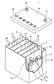
- FIG. 1 shows the appearance of an example of a lead storage battery according to an embodiment of the present invention.
- the lead-acid battery 1 includes an electric tank 12 for accommodating a plate group 11 and an electrolytic solution (not shown).
- the inside of the electric tank 12 is partitioned into a plurality of cell chambers 14 by a partition wall 13.
- One electrode plate group 11 is housed in each cell chamber 14.
- the opening of the battery case 12 is closed by a lid 15 including a negative electrode terminal 16 and a positive electrode terminal 17.
- the lid 15 is provided with a liquid spout 18 for each cell chamber. At the time of refilling water, the liquid spout 18 is removed and the refilling liquid is replenished.
- the liquid spout 18 may have a function of discharging the gas generated in the cell chamber 14 to the outside of the battery.
- the electrode plate group 11 is configured by laminating a plurality of negative electrode plates 2 and positive electrode plates 3 via a separator 4, respectively.
- the bag-shaped separator 4 accommodating the negative electrode plate 2 is shown, but the form of the separator is not particularly limited.
- the negative electrode shelf portion 6 for connecting the plurality of negative electrode plates 2 in parallel is connected to the through connection body 8, and the positive electrode shelf portion for connecting the plurality of positive electrode plates 3 in parallel is connected.
- 5 is connected to the positive electrode column 7.
- the positive electrode column 7 is connected to the positive electrode terminal 17 outside the lid 15.
- the negative electrode column 9 is connected to the negative electrode shelf portion 6, and the penetration connecting body 8 is connected to the positive electrode shelf portion 5.
- the negative electrode column 9 is connected to the negative electrode terminal 16 outside the lid 15.
- Each through-connecting body 8 passes through a through-hole provided in the partition wall 13 and connects the electrode plates 11 of the adjacent cell chambers 14 in series.
- the positive electrode shelf 5 is formed by welding the ears provided on the upper part of each positive electrode plate 3 by a cast-on-strap method or a burning method.
- the negative electrode shelf portion 6 is also formed by welding the selvage portions provided on the upper portions of the negative electrode plates 2 as in the case of the positive electrode shelf portion 5.
- the lid 15 of the lead storage battery has a single structure (single lid), but is not limited to the case shown in the illustrated example.
- the lid 15 may have, for example, a double structure including an inner lid and an outer lid (or upper lid).
- the lid having a double structure is provided with a reflux structure between the inner lid and the outer lid for returning the electrolytic solution to the inside of the battery (inside the inner lid) from the reflux port provided in the inner lid. May be good.
- the lead-acid batteries according to one aspect of the present invention are summarized below.
- the electrode plate group includes a plurality of laminated positive electrode plates and a plurality of negative electrode plates.
- the negative electrode plate contains a negative electrode material and contains a negative electrode material.
- the negative electrode material contains a polymer compound and contains.
- the polymer compound has a peak in the range of 3.2 ppm or more and 3.8 ppm or less in the chemical shift of 1 H-NMR spectrum measured using deuterated chloroform as a solvent.
- the content of the polymer compound in the negative electrode material is 15 ppm or more and 400 ppm or less on a mass basis.
- a lead-acid battery in which the pull-out load when pulling out the electrode plate group from the electric tank is 1.5 times or more the own weight of the electrode plate group.
- the electrode plate group includes a plurality of laminated positive electrode plates and a plurality of negative electrode plates.
- the negative electrode plate contains a negative electrode material and contains a negative electrode material.
- the negative electrode material contains a polymer compound and contains.
- the polymer compound contains an oxyC 2-4 alkylene unit as a repeating structure and contains.
- the content of the polymer compound in the negative electrode material is 15 ppm or more and 400 ppm or less on a mass basis.
- a lead-acid battery in which the pull-out load when pulling out the electrode plate group from the electric tank is 1.5 times or more the own weight of the electrode plate group.
- the polymer compound is selected from the group consisting of a hydroxy compound containing the repeating structure of the oxyC 2-4 alkylene unit, an etherified product of the hydroxy compound, and an esterified product of the hydroxy compound. It may contain at least one compound.
- the polymer compound may be at least one selected from the group consisting of polyethylene glycol, an esterified product of polyethylene glycol, polypropylene glycol, and an esterified product of polypropylene glycol. ..
- the polymer compound may be polypropylene glycol.
- the number average molecular weight of the polymer compound may be 1000 or more.
- the lead storage battery (X) disclosed in this specification includes a electrode plate group, an electrolytic solution, the electrode plate group, and an electric tank for accommodating the electrolytic solution, and the electrode plate group. Includes a plurality of laminated positive electrode plates and a plurality of negative electrode plates, and the pulling load when the electrode plate group is pulled out from the electric tank is 1.5 times or more the own weight of the electrode plate group.
- the lead-acid battery (X) may or may not contain the polymer compound (P).
- the content of the polymer compound (P) in the negative electrode electrode material may be less than 15 ppm (for example, greater than 0 ppm and less than 15 ppm) on a mass basis.
- the portion other than the polymer compound (P) can be configured in the same manner as the above-mentioned lead storage battery containing the polymer compound (P). According to the lead storage battery (X), as shown in the embodiment, high charge acceptance performance can be realized.
- the amount of overcharged electricity is measured and evaluated by the following method.
- the lead-acid battery to be measured is subjected to a high-temperature light load test of 1220 cycles at 75 ° C. ⁇ 3 ° C. in order to make the overcharge condition more than the normal 4-minute-10-minute test specified in JIS D5301.
- the high temperature load test is carried out with the lead storage battery placed in a water tank at 75 ° C.
- One cycle of high temperature and light load test consists of 1 minute discharge and 10 minutes charge.
- Discharging is performed with a current of 25 A.
- Charging is performed with a voltage of 2.47 V / cell and a current of 25 A.
- the amount of overcharged electricity (charged electricity amount-discharged electricity amount) in each cycle of 1 to 1220 cycles is totaled to obtain a total value.
- the amount of overcharged electricity (Ah) per cycle is obtained by dividing (dividing) the total value by the number of cycles. The smaller the amount of overcharged electricity, the better the characteristics of the battery, and the smaller the decrease in the electrolytic solution.
- the overcharged electricity amount of each battery is evaluated from the relative value (ratio) of the overcharged electricity amount (Ah) of each battery when the overcharged electricity amount (Ah) per cycle of the battery A1 is 100. .. The lower the relative value, the better the characteristics.
- the charge acceptance performance is measured and evaluated by the following method. First, the lead-acid battery to be measured is brought into a fully charged state by charging it according to the method described in the "fully charged state”. Next, the battery is discharged at 6.4 A for 30 minutes, left for 16 hours, and further charged at a constant voltage of 2.42 V / cell. The upper limit of the current during charging is 200 A. Then, the integrated charging electric energy (Ah) for 10 seconds from the start of charging is measured. These operations are performed with the batteries placed in a water tank at 25 ° C ⁇ 2 ° C. The larger the integrated charge electricity amount, the higher the charge acceptance performance (the better the characteristics of the battery). The charge acceptance performance of each battery is evaluated from the relative value (ratio) of the integrated charge electricity amount (Ah) of each battery when the integrated charge electricity amount (Ah) of the battery A1 is 100. The higher the relative value, the better the characteristics.
- the “penetration short circuit” means a short circuit caused by dendrites grown from the electrodes penetrating the separator and reaching the adjacent electrodes.
- 20 lead-acid batteries to be evaluated were prepared.
- those lead-acid batteries are placed in a constant temperature water tank at 25 ° C., and the charge / discharge cycle composed of the following steps 1 to 4 is repeated 5 times. This test is performed under conditions that promote the occurrence of osmotic short circuits.
- Step 1 Discharge the lead-acid battery at a constant current of 0.05 C (A) until the voltage reaches 1.0 V / cell.
- C is a numerical value when the rated capacity is expressed in the unit of "Ah (amp-hour)".
- Step 2 A 10 ⁇ resistor is connected to the lead-acid battery that has undergone step 1 and discharged for 28 days.
- Step 3 The lead-acid battery that has undergone step 2 is charged at a constant voltage of 2.4 V / cell for 10 minutes. At this time, the maximum charge current is 50 A.
- Step 4 Charge with a constant current of 0.05 C (A) for 27 hours.
- the batteries were disassembled and the presence or absence of a short circuit was visually confirmed. From this test, the occurrence rate of short circuit (penetration short circuit) is determined.
- Example 1 a plurality of types of lead-acid batteries are produced by changing the content of the polymer compound (P) in the negative electrode electrode material and the pull-out load of the electrode plate group.
- the positive electrode plate and the negative electrode plate of these lead-acid batteries are manufactured as follows.
- PPG polypropylene glycol
- each component is added so that the content of barium sulfate in the negative electrode electrode material is 0.4% by mass, the content of carbon black is 0.2% by mass, and the content of the organic shrinkage proofing agent is 0.1% by mass.
- the negative electrode paste is filled in the mesh portion of the expanded lattice made of Pb—Ca—Sn alloy and aged and dried to obtain an unchemicald negative electrode plate.
- the test battery has a rated voltage of 2 V and a 20-hour rate rated capacity of 60 Ah.
- the electrode plate group of the test battery is composed of 7 positive electrode plates and 8 negative electrode plates.
- the positive electrode plate is housed in a bag-shaped separator formed of a microporous polyethylene film, and is alternately laminated with the negative electrode plate to form a group of electrode plates.
- a group of electrode plates is housed in a polypropylene electric tank together with an electrolytic solution (sulfuric acid aqueous solution) and chemically formed in the electric tank to produce a liquid-type lead-acid battery.
- the specific gravity of the electrolytic solution after chemical conversion is 1.28 (20 ° C. conversion).
- a spacer is placed between the inner wall of the battery case and the electrode plate at the end of the electrode plate group, if necessary. At this time, the thickness of the spacer is adjusted so that the pull-out load (pull-out load of the electrode plate group) changes.
- the thicknesses of the negative electrode plate and the positive electrode plate are 1.5 mm and 1.8 mm, respectively, and the maximum thickness T of the separator is 0.8 mm.
- the total V SUM of the integrated values is the integrated value of the integrated value V 1 , the integrated value of the peak of the -CH 2- group hydrogen atom bonded to the oxygen atom, and the -CH ⁇ group hydrogen atom bonded to the oxygen atom. It is the sum with the integrated value of the peak.
- a battery having a relative value of 105 or more is A (good), a battery having a relative value of 100 or more and less than 105 is B (possible), and a battery having a relative value of less than 100 is C (impossible).
- a lead-acid battery having a permeation short-circuit occurrence rate of 10% or less is defined as A (good), and a battery having a penetration short-circuit occurrence rate of more than 10% is designated as C (impossible).
- lead-acid batteries having a pull-out load ratio of 1.5 or more and a polymer (P) content of 15 ppm or more and 400 ppm or less have a small amount of overcharge electricity and accept charge. High performance and low incidence of seepage short circuit. That is, the lead-acid battery can achieve a small amount of overcharge electricity, a high charge acceptance performance, and a low penetration short circuit occurrence rate in a well-balanced manner.
- the withdrawal load ratio is 1.4 or less
- the charge acceptance performance is greatly deteriorated as the content of the polymer compound (P) increases.
- the pull-out load ratio is 1.5 or more and the content of the polymer compound (P) is in the range of 15 ppm to 400 ppm
- the charge acceptance performance does not significantly deteriorate even if the content of the polymer compound (P) increases.
- the content of the polymer compound (P) is 500 ppm, the deterioration of the charge acceptance performance becomes large.
- the charge acceptance performance is improved when the content of the polymer compound (P) is in the range of 50 ppm to 200 ppm as compared with the case where the content is 15 ppm.
- the lead-acid battery has a high pull-out load ratio of 1.5 or more and a polymer compound (P) content of 15 ppm or more and 400 ppm or less.
- P polymer compound
- the polymer compound (P) is considered to thinly cover the surface of the negative electrode active material. Therefore, it is considered that the polymer compound (P) suppresses the growth of dendrite due to the precipitation of lead ions dissolved from the negative electrode active material on the negative electrode active material.
- the pull-out load ratio is high, the distance between the plates becomes narrow and a permeation short circuit is generally likely to occur.
- the negative electrode material contains an appropriate amount of the polymer compound (P)
- the growth of dendrites is suppressed, so that permeation short circuits can be suppressed even if the electrode plate spacing is narrow.
- the pull-out load when the pull-out load is high, it is considered that the movement of the polymer compound (P) is suppressed and the polymer compound (P) tends to stay in the negative electrode plate. As a result, the higher the pull-out load, the higher the short-circuit suppressing effect of the polymer compound (P) may be. Further, when the pull-out load ratio is high, the distance between the plates is narrow, so that the charge transfer resistance can be reduced and the charge acceptance performance is improved. When the concentration of the polymer compound (P) is high, the ratio of the polymer compound (P) covering the surface of the negative electrode active material tends to be high, and the charge acceptability tends to decrease.
- the lead-acid battery of the present invention achieves a small amount of overcharge electricity, a high charge acceptance performance, and a low penetration short circuit occurrence rate in a well-balanced manner for the above reasons.
- Example 2 In Example 2, a plurality of types of lead are used under the same conditions as the lead-acid battery A24 (see Table 1) of Example 1 except that the number average molecular weight Mn of polypropylene glycol (PPG, polymer compound (P)) is changed. Make a storage battery. The plurality of types of lead-acid batteries are evaluated in the same manner as in Example 1. Table 3 shows some of the manufacturing conditions for these lead-acid batteries and the evaluation results. The evaluation of the lead storage battery B3 shows the evaluation of the lead storage battery A24. The meanings of the notes (* 1) to (* 5) in Table 3 are the same as the meanings of the notes (* 1) to (* 5) in Tables 1 and 2, respectively.
- Example 3 a plurality of types of lead-acid batteries are produced under the same conditions as the lead-acid battery A25 (see Table 1) of Example 1 except that the type of the polymer compound (P) is changed.
- the plurality of types of lead-acid batteries are evaluated in the same manner as in Example 1.
- Table 4 shows some of the manufacturing conditions for these lead-acid batteries and the evaluation results.
- the evaluation of the lead storage battery C1 shows the evaluation of the lead storage battery A25.
- the meanings of the notes (* 1) to (* 5) in Table 4 are the same as the meanings of the notes (* 1) to (* 5) in Tables 1 and 2, respectively.
- the content of each polymer compound (P) in the negative electrode electrode material is 50 ppm (mass ratio).
- the number average molecular weight (Mn) of each polymer compound (P) is in the range of 1800 to 2000.
- Polyethylene glycol (PEG) is used as the polymer compound (P) of the lead storage battery C2.
- Polyoxyethylene polyoxypropylene butyl ether is used as the polymer compound 1 of the lead storage battery C3.
- the ratio of the oxypropylene unit to the total monomer unit of the polymer compound 1 is 43 mol%.
- Polyoxypropylene acetate is used as the polymer compound 2 of the lead storage battery C4.
- Each of the polymer compounds used in Example 3 has a peak in the range of 3.2 ppm or more and 3.8 ppm or less in the chemical shift of 1 H-NMR spectrum measured using deuterated chloroform as a solvent.
- the present invention can be used for lead storage batteries.
- Electrode plate group 12 Electric tank 13: Partition wall 14: Cell chamber 15: Cover 16: Negative electrode terminal 17: Positive electrode terminal
Landscapes
- Chemical & Material Sciences (AREA)
- Chemical Kinetics & Catalysis (AREA)
- Electrochemistry (AREA)
- General Chemical & Material Sciences (AREA)
- Engineering & Computer Science (AREA)
- Manufacturing & Machinery (AREA)
- Secondary Cells (AREA)
Priority Applications (2)
| Application Number | Priority Date | Filing Date | Title |
|---|---|---|---|
| EP21897604.1A EP4246620A4 (en) | 2020-11-27 | 2021-10-28 | LEAD-ACID STORAGE BATTERY |
| JP2022565149A JP7754108B2 (ja) | 2020-11-27 | 2021-10-28 | 鉛蓄電池 |
Applications Claiming Priority (2)
| Application Number | Priority Date | Filing Date | Title |
|---|---|---|---|
| JP2020197578 | 2020-11-27 | ||
| JP2020-197578 | 2020-11-27 |
Publications (1)
| Publication Number | Publication Date |
|---|---|
| WO2022113628A1 true WO2022113628A1 (ja) | 2022-06-02 |
Family
ID=81755530
Family Applications (1)
| Application Number | Title | Priority Date | Filing Date |
|---|---|---|---|
| PCT/JP2021/039748 Ceased WO2022113628A1 (ja) | 2020-11-27 | 2021-10-28 | 鉛蓄電池 |
Country Status (3)
| Country | Link |
|---|---|
| EP (1) | EP4246620A4 (https=) |
| JP (1) | JP7754108B2 (https=) |
| WO (1) | WO2022113628A1 (https=) |
Citations (7)
| Publication number | Priority date | Publication date | Assignee | Title |
|---|---|---|---|---|
| JPS60182662A (ja) | 1984-02-28 | 1985-09-18 | Japan Storage Battery Co Ltd | 鉛蓄電池 |
| JPH09147869A (ja) * | 1995-11-17 | 1997-06-06 | Shin Kobe Electric Mach Co Ltd | 鉛蓄電池 |
| JP2003051288A (ja) | 2001-08-08 | 2003-02-21 | Furukawa Battery Co Ltd:The | 鉛蓄電池用電槽 |
| JP2009123433A (ja) | 2007-11-13 | 2009-06-04 | Gs Yuasa Corporation:Kk | 制御弁式鉛蓄電池の製造方法 |
| JP2019071165A (ja) * | 2016-03-01 | 2019-05-09 | 日立化成株式会社 | 鉛蓄電池用樹脂、電極、鉛蓄電池及び自動車 |
| WO2020080420A1 (ja) * | 2018-10-16 | 2020-04-23 | 株式会社Gsユアサ | 鉛蓄電池 |
| WO2020241884A1 (ja) * | 2019-05-31 | 2020-12-03 | 株式会社Gsユアサ | 鉛蓄電池 |
Family Cites Families (7)
| Publication number | Priority date | Publication date | Assignee | Title |
|---|---|---|---|---|
| JPS5147237A (https=) * | 1974-10-18 | 1976-04-22 | Yuasa Battery Co Ltd | |
| CN101937996B (zh) * | 2010-08-26 | 2012-11-28 | 风帆股份有限公司 | 电动助力车用胶体铅酸蓄电池负极铅膏及制备方法 |
| CN102024992A (zh) * | 2010-11-02 | 2011-04-20 | 江苏双登集团有限公司 | 铅酸蓄电池胶体电解液及制备方法 |
| CN103647051B (zh) * | 2013-11-18 | 2016-05-25 | 河南超威电源有限公司 | 铅膏组合物及其制备方法 |
| EP3294931A4 (en) * | 2015-05-13 | 2018-12-26 | Aqua Metals Inc. | Electrodeposited lead composition, methods of production, and uses |
| EP4234630A3 (en) * | 2017-10-04 | 2023-10-04 | Mitsubishi Chemical Corporation | Rubber-containing graft polymer, resin composition containing rubber-containing graft polymer, and shaped article thereof |
| CN107919463B (zh) * | 2017-10-26 | 2020-10-09 | 江苏明思维照明科技有限公司 | 一种铅炭电池负极材料、铅炭电池和制备方法 |
-
2021
- 2021-10-28 WO PCT/JP2021/039748 patent/WO2022113628A1/ja not_active Ceased
- 2021-10-28 EP EP21897604.1A patent/EP4246620A4/en not_active Withdrawn
- 2021-10-28 JP JP2022565149A patent/JP7754108B2/ja active Active
Patent Citations (7)
| Publication number | Priority date | Publication date | Assignee | Title |
|---|---|---|---|---|
| JPS60182662A (ja) | 1984-02-28 | 1985-09-18 | Japan Storage Battery Co Ltd | 鉛蓄電池 |
| JPH09147869A (ja) * | 1995-11-17 | 1997-06-06 | Shin Kobe Electric Mach Co Ltd | 鉛蓄電池 |
| JP2003051288A (ja) | 2001-08-08 | 2003-02-21 | Furukawa Battery Co Ltd:The | 鉛蓄電池用電槽 |
| JP2009123433A (ja) | 2007-11-13 | 2009-06-04 | Gs Yuasa Corporation:Kk | 制御弁式鉛蓄電池の製造方法 |
| JP2019071165A (ja) * | 2016-03-01 | 2019-05-09 | 日立化成株式会社 | 鉛蓄電池用樹脂、電極、鉛蓄電池及び自動車 |
| WO2020080420A1 (ja) * | 2018-10-16 | 2020-04-23 | 株式会社Gsユアサ | 鉛蓄電池 |
| WO2020241884A1 (ja) * | 2019-05-31 | 2020-12-03 | 株式会社Gsユアサ | 鉛蓄電池 |
Non-Patent Citations (1)
| Title |
|---|
| See also references of EP4246620A4 |
Also Published As
| Publication number | Publication date |
|---|---|
| EP4246620A4 (en) | 2024-11-20 |
| EP4246620A1 (en) | 2023-09-20 |
| JP7754108B2 (ja) | 2025-10-15 |
| JPWO2022113628A1 (https=) | 2022-06-02 |
Similar Documents
| Publication | Publication Date | Title |
|---|---|---|
| TWI857051B (zh) | 鉛蓄電池 | |
| JP7173322B2 (ja) | 鉛蓄電池 | |
| JP7111099B2 (ja) | 鉛蓄電池 | |
| JP2021099920A (ja) | 鉛蓄電池 | |
| WO2022113633A1 (ja) | 鉛蓄電池 | |
| JP7501528B2 (ja) | 鉛蓄電池 | |
| WO2020241547A1 (ja) | 鉛蓄電池 | |
| JP7677347B2 (ja) | 鉛蓄電池 | |
| WO2022113628A1 (ja) | 鉛蓄電池 | |
| JP7661978B2 (ja) | 鉛蓄電池 | |
| JP7605107B2 (ja) | 鉛蓄電池 | |
| JP7679841B2 (ja) | 鉛蓄電池 | |
| WO2020241880A1 (ja) | 鉛蓄電池 | |
| WO2020241885A1 (ja) | 鉛蓄電池 | |
| JP7647070B2 (ja) | 鉛蓄電池 | |
| WO2020241883A1 (ja) | 鉛蓄電池 | |
| JP7533166B2 (ja) | 鉛蓄電池 | |
| JP7798037B2 (ja) | 鉛蓄電池 | |
| JP7694582B2 (ja) | 鉛蓄電池 | |
| JP7452538B2 (ja) | 鉛蓄電池 | |
| JP7718427B2 (ja) | 鉛蓄電池 | |
| WO2022113627A1 (ja) | 鉛蓄電池 | |
| WO2022113635A1 (ja) | 鉛蓄電池 | |
| WO2020241879A1 (ja) | 鉛蓄電池 | |
| EP4246621A1 (en) | Lead-acid battery |
Legal Events
| Date | Code | Title | Description |
|---|---|---|---|
| 121 | Ep: the epo has been informed by wipo that ep was designated in this application |
Ref document number: 21897604 Country of ref document: EP Kind code of ref document: A1 |
|
| ENP | Entry into the national phase |
Ref document number: 2022565149 Country of ref document: JP Kind code of ref document: A |
|
| NENP | Non-entry into the national phase |
Ref country code: DE |
|
| ENP | Entry into the national phase |
Ref document number: 2021897604 Country of ref document: EP Effective date: 20230613 |
|
| WWW | Wipo information: withdrawn in national office |
Ref document number: 2021897604 Country of ref document: EP |