WO2022113599A1 - 腕時計及び腕時計型表示装置 - Google Patents
腕時計及び腕時計型表示装置 Download PDFInfo
- Publication number
- WO2022113599A1 WO2022113599A1 PCT/JP2021/039218 JP2021039218W WO2022113599A1 WO 2022113599 A1 WO2022113599 A1 WO 2022113599A1 JP 2021039218 W JP2021039218 W JP 2021039218W WO 2022113599 A1 WO2022113599 A1 WO 2022113599A1
- Authority
- WO
- WIPO (PCT)
- Prior art keywords
- display
- wristwatch
- unit
- user
- information
- Prior art date
- Legal status (The legal status is an assumption and is not a legal conclusion. Google has not performed a legal analysis and makes no representation as to the accuracy of the status listed.)
- Ceased
Links
Images













Classifications
-
- G—PHYSICS
- G04—HOROLOGY
- G04G—ELECTRONIC TIME-PIECES
- G04G9/00—Visual time or date indication means
- G04G9/0064—Visual time or date indication means in which functions not related to time can be displayed
- G04G9/007—Visual time or date indication means in which functions not related to time can be displayed combined with a calculator or computing means
-
- A—HUMAN NECESSITIES
- A61—MEDICAL OR VETERINARY SCIENCE; HYGIENE
- A61B—DIAGNOSIS; SURGERY; IDENTIFICATION
- A61B5/00—Measuring for diagnostic purposes; Identification of persons
- A61B5/68—Arrangements of detecting, measuring or recording means, e.g. sensors, in relation to patient
- A61B5/6801—Arrangements of detecting, measuring or recording means, e.g. sensors, in relation to patient specially adapted to be attached to or worn on the body surface
- A61B5/6802—Sensor mounted on worn items
- A61B5/681—Wristwatch-type devices
-
- G—PHYSICS
- G04—HOROLOGY
- G04G—ELECTRONIC TIME-PIECES
- G04G21/00—Input or output devices integrated in time-pieces
- G04G21/02—Detectors of external physical values, e.g. temperature
-
- G—PHYSICS
- G04—HOROLOGY
- G04G—ELECTRONIC TIME-PIECES
- G04G21/00—Input or output devices integrated in time-pieces
- G04G21/02—Detectors of external physical values, e.g. temperature
- G04G21/025—Detectors of external physical values, e.g. temperature for measuring physiological data
-
- G—PHYSICS
- G04—HOROLOGY
- G04G—ELECTRONIC TIME-PIECES
- G04G21/00—Input or output devices integrated in time-pieces
- G04G21/08—Touch switches specially adapted for time-pieces
-
- G—PHYSICS
- G04—HOROLOGY
- G04G—ELECTRONIC TIME-PIECES
- G04G9/00—Visual time or date indication means
-
- G—PHYSICS
- G06—COMPUTING OR CALCULATING; COUNTING
- G06F—ELECTRIC DIGITAL DATA PROCESSING
- G06F3/00—Input arrangements for transferring data to be processed into a form capable of being handled by the computer; Output arrangements for transferring data from processing unit to output unit, e.g. interface arrangements
- G06F3/01—Input arrangements or combined input and output arrangements for interaction between user and computer
- G06F3/03—Arrangements for converting the position or the displacement of a member into a coded form
- G06F3/033—Pointing devices displaced or positioned by the user, e.g. mice, trackballs, pens or joysticks; Accessories therefor
- G06F3/0346—Pointing devices displaced or positioned by the user, e.g. mice, trackballs, pens or joysticks; Accessories therefor with detection of the device orientation or free movement in a three-dimensional [3D] space, e.g. 3D mice, 6-DOF [six degrees of freedom] pointers using gyroscopes, accelerometers or tilt-sensors
-
- G—PHYSICS
- G06—COMPUTING OR CALCULATING; COUNTING
- G06F—ELECTRIC DIGITAL DATA PROCESSING
- G06F3/00—Input arrangements for transferring data to be processed into a form capable of being handled by the computer; Output arrangements for transferring data from processing unit to output unit, e.g. interface arrangements
- G06F3/01—Input arrangements or combined input and output arrangements for interaction between user and computer
- G06F3/048—Interaction techniques based on graphical user interfaces [GUI]
- G06F3/0487—Interaction techniques based on graphical user interfaces [GUI] using specific features provided by the input device, e.g. functions controlled by the rotation of a mouse with dual sensing arrangements, or of the nature of the input device, e.g. tap gestures based on pressure sensed by a digitiser
- G06F3/0488—Interaction techniques based on graphical user interfaces [GUI] using specific features provided by the input device, e.g. functions controlled by the rotation of a mouse with dual sensing arrangements, or of the nature of the input device, e.g. tap gestures based on pressure sensed by a digitiser using a touch-screen or digitiser, e.g. input of commands through traced gestures
-
- G—PHYSICS
- G09—EDUCATION; CRYPTOGRAPHY; DISPLAY; ADVERTISING; SEALS
- G09G—ARRANGEMENTS OR CIRCUITS FOR CONTROL OF INDICATING DEVICES USING STATIC MEANS TO PRESENT VARIABLE INFORMATION
- G09G3/00—Control arrangements or circuits, of interest only in connection with visual indicators other than cathode-ray tubes
- G09G3/20—Control arrangements or circuits, of interest only in connection with visual indicators other than cathode-ray tubes for presentation of an assembly of a number of characters, e.g. a page, by composing the assembly by combination of individual elements arranged in a matrix no fixed position being assigned to or needed to be assigned to the individual characters or partial characters
- G09G3/22—Control arrangements or circuits, of interest only in connection with visual indicators other than cathode-ray tubes for presentation of an assembly of a number of characters, e.g. a page, by composing the assembly by combination of individual elements arranged in a matrix no fixed position being assigned to or needed to be assigned to the individual characters or partial characters using controlled light sources
- G09G3/30—Control arrangements or circuits, of interest only in connection with visual indicators other than cathode-ray tubes for presentation of an assembly of a number of characters, e.g. a page, by composing the assembly by combination of individual elements arranged in a matrix no fixed position being assigned to or needed to be assigned to the individual characters or partial characters using controlled light sources using electroluminescent panels
- G09G3/32—Control arrangements or circuits, of interest only in connection with visual indicators other than cathode-ray tubes for presentation of an assembly of a number of characters, e.g. a page, by composing the assembly by combination of individual elements arranged in a matrix no fixed position being assigned to or needed to be assigned to the individual characters or partial characters using controlled light sources using electroluminescent panels semiconductive, e.g. using light-emitting diodes [LED]
-
- A—HUMAN NECESSITIES
- A61—MEDICAL OR VETERINARY SCIENCE; HYGIENE
- A61B—DIAGNOSIS; SURGERY; IDENTIFICATION
- A61B2562/00—Details of sensors; Constructional details of sensor housings or probes; Accessories for sensors
- A61B2562/02—Details of sensors specially adapted for in-vivo measurements
- A61B2562/0219—Inertial sensors, e.g. accelerometers, gyroscopes, tilt switches
-
- G—PHYSICS
- G09—EDUCATION; CRYPTOGRAPHY; DISPLAY; ADVERTISING; SEALS
- G09G—ARRANGEMENTS OR CIRCUITS FOR CONTROL OF INDICATING DEVICES USING STATIC MEANS TO PRESENT VARIABLE INFORMATION
- G09G2300/00—Aspects of the constitution of display devices
- G09G2300/02—Composition of display devices
- G09G2300/026—Video wall, i.e. juxtaposition of a plurality of screens to create a display screen of bigger dimensions
-
- G—PHYSICS
- G09—EDUCATION; CRYPTOGRAPHY; DISPLAY; ADVERTISING; SEALS
- G09G—ARRANGEMENTS OR CIRCUITS FOR CONTROL OF INDICATING DEVICES USING STATIC MEANS TO PRESENT VARIABLE INFORMATION
- G09G2354/00—Aspects of interface with display user
Definitions
- the present invention relates to a wristwatch and a wristwatch-type display device.
- FIG. 36 is a diagram shown for explaining the conventional wristwatch 900.
- the wristwatch 900 shown in FIG. 36 is the wristwatch described in FIG. 13 in Patent Document 2.
- 36 (a) is a perspective view of the wristwatch 900 at the time of display
- FIG. 36 (b) is a perspective view of the wristwatch 900 at the time of non-display.
- the wristwatch 900 is a wristwatch that does not display anything, let alone a clock display, when it is hidden. It provides value.
- an object of the present invention is to provide a wristwatch and a wristwatch-type display device having a new value that has never existed before.
- the wristwatch of the present invention is a wristwatch, which is a rectangular wristwatch body and, of the six surfaces constituting the surface of the wristwatch body, "the upper surface opposite to the lower surface facing the user's arm side during use”. , And at least two display units formed over the entire area of "at least one side surface of the four sides", a display control unit that controls the display of each of the at least two display units, and the wristwatch.
- the display control unit includes a detection unit that detects at least one of position information, posture information of the wristwatch, movement information of the wristwatch, and health-related information of the user of the wristwatch. It is characterized by having a function of controlling the display of each of the at least two display units based on the at least one information detected by the unit.
- the display control unit has a function of controlling the display of each of the at least two display units so that the images displayed on each of the at least two display units are interlocked or related. Is preferable.
- the "interlocking" here includes the case where the image displayed on at least two display units moves seamlessly across the at least two display units. Further, a case where at least two display units change the lighting state one after another based on a predetermined rule or randomly is also included. For example, one of at least two display units may be displayed in red, and then the other display unit may be displayed in the same color or different colors. It is also included that each display unit sequentially and independently displays based on a predetermined rule.
- the at least two display units are five display units formed over the entire area of each of the five surfaces composed of the upper surface and the four side surfaces. That is, the wristwatch of the present invention comprises a rectangular parallelepiped wristwatch body, five display units formed over the entire area of each of the five surfaces excluding the lower surface of the six surfaces constituting the surface of the wristwatch body, and the five display units.
- a display control unit that controls each display, and a detection that detects at least one of the position information of the wristwatch, the posture information of the wristwatch, the movement information of the wristwatch, and the health-related information of the user of the wristwatch. It is preferable that the display control unit has a function of controlling the display of each of the five display units based on at least one piece of information detected by the detection unit.
- the five surfaces of the wristwatch body excluding the lower surface, have no pattern over the entire area when nothing is displayed on the five display units.
- the five display units are composed of five organic EL display sheets or five micro LED display sheets, and the five organic EL display sheets or five micro LED display sheets. Is preferably attached to the five surfaces of the wristwatch body.
- the five display units are composed of one organic EL display sheet or one micro LED display sheet, and the one organic EL display sheet or one micro LED display sheet. Is preferably bent and attached to the wristwatch body so as to follow the outer shape of the wristwatch body.
- a first electrode group for supplying electric power and an electric signal to the organic EL display sheet or the micro LED display sheet is exposed and provided on the five surfaces of the watch body.
- the second electrode group for receiving the electric power and the electric signal from the first electrode group is located at a position corresponding to the first electrode group.
- a drive circuit for supplying an electric signal for controlling the lighting state of each pixel of the organic EL display sheet or the micro LED display sheet is provided, and the first electrode group and the second electrode are provided. It is preferable that each group is electrically connected.
- the gap existing between the five display units is filled with a black member so that the gap cannot be visually recognized.
- the five display units are coated and cured with a protective member so as to cover the entire five display units.
- the display control unit controls the display of each of the five display units so that the inside of the wristwatch body can be seen through from the user's point of view. ..
- the five display units are composed of a touch panel.
- the display control unit is a display control unit of each of the five display units so that when the user swipes the touch panel surface with a finger, the image is switched according to the swipe operation. It is preferable to control the display.
- the detection unit is a user of the wristwatch imaged by one or more image pickup elements installed at any part of the wristwatch and the one or more image pickup elements.
- a calculation unit for extracting information on the positional relationship between the eye of the user of the wristwatch and the wristwatch from an image of the eye is provided, and the detection unit serves as position information of the wristwatch of the user of the wristwatch. It is preferable to detect information regarding the positional relationship between the eye and the wristwatch.
- the detection unit is a three-dimensional acceleration sensor that detects the posture information of the wristwatch, and the detection unit relates to the three-dimensional posture of the wristwatch as the posture information of the wristwatch. It is preferable to detect information.
- the detection unit is a three-dimensional acceleration sensor that detects the motion information of the wristwatch, and the detection unit relates to the three-dimensional movement of the wristwatch as the motion information of the wristwatch. It is preferable to detect information.
- the detection unit is a pulse meter (or heart rate monitor), a body temperature monitor, a sphygmomanometer, an electrocardiograph, or a three-dimensional acceleration sensor that detects health-related information of the user of the watch. It is preferable that the detection unit detects information on the pulse (or heart rate), body temperature, blood pressure, or activity of the user of the wristwatch as health-related information of the user of the wristwatch.
- the watch-type display device of the present invention is a watch-type display device, and of the six surfaces constituting the surface of the rectangular watch-type display device main body and the watch-type display device main body, "the user at the time of use". At least two display units formed over the entire area of "the upper surface opposite to the lower surface facing the arm side” and “at least one side surface of the four sides", and each of the at least two display units.
- the display control unit that controls the display, the position information of the watch-type display device body, the attitude information of the watch-type display device body, the movement information of the watch-type display device body, and the user of the watch-type display device body.
- the display control unit includes a detection unit that detects at least one of the health-related information of the above, and the display control unit is each of the at least two display units based on the at least one information detected by the detection unit. It is characterized by having a function of controlling the display.
- the display control unit controls the display of each of the at least two display units so that the images displayed on each of the at least two display units are interlocked or related to each other. It is also preferable to have a function.
- the at least two display units may be five display units formed over the entire area of each of the five surfaces composed of the upper surface and the four side surfaces. preferable.
- the display control unit displays each of the five display units so that the inside of the wristwatch-type display device main body can be seen through from the user's point of view. It is preferable to control.
- the wristwatch-type display device of the present invention also preferably has each of the features of the wristwatch of the present invention.
- the wristwatch of the present invention and the wristwatch-type display device of the present invention as can be seen from the embodiments described later, various aspects are utilized by utilizing the side surfaces in addition to the upper surface of the rectangular wristwatch body and the wristwatch-type display device body. It is possible to display various images with.
- the information detected by the detection unit position information of the wristwatch and the wristwatch-type display device, posture information of the wristwatch and the wristwatch-type display device, motion information of the wristwatch and the wristwatch-type display device, and the user of the wristwatch and the wristwatch-type display device).
- FIG. It is a figure which shows for demonstrating the 1st display aspect in the wristwatch 1 which concerns on Embodiment 1.
- FIG. It is a figure which shows for demonstrating the 2nd display aspect in the wristwatch 1 which concerns on Embodiment 1.
- FIG. It is a figure which shows for demonstrating the 3rd display aspect in the wristwatch 1 which concerns on Embodiment 1.
- FIG. It is a figure which shows for demonstrating the 4th display aspect in the wristwatch 1 which concerns on Embodiment 1.
- FIG. It is a figure for demonstrating the method of specifying the direction in which the user of the wristwatch 1 which concerns on Embodiment 1 looks at the wristwatch 1.
- FIG. 3 is a diagram showing a series of movements in which the current time protrudes to one or more side display units of the side display units 211 to 214 in addition to the top surface display unit 210 in a pre-programmed display mode.
- FIG. 1 It is a figure which shows for demonstrating the 3rd display aspect of the wristwatch 1 which concerns on Embodiment 2.
- FIG. It is a figure which shows for demonstrating the 4th display aspect of the wristwatch 1 which concerns on Embodiment 2.
- FIG. It is a figure which shows for demonstrating the 5th display aspect of the wristwatch 1 which concerns on Embodiment 2.
- FIG. It is a figure which shows for demonstrating the 7th display aspect of the wristwatch 1 which concerns on Embodiment 2.
- FIG. It is a figure which shows for demonstrating the 8th display aspect of the wristwatch 1 which concerns on Embodiment 2.
- FIG. It is a figure which shows the state which looked at the main part of the wristwatch 1 which concerns on Embodiment 3 from the lower surface.
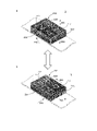
- FIG. 1 is a diagram showing a state in which the wristwatch 1 according to the first embodiment is attached to the left arm of the user.
- 1 (a) is a diagram showing the wristwatch 1 together with the upper body of the user
- FIG. 1 (b) is an enlarged view of the wristwatch 1 viewed from a different angle from FIG. 1 (a).
- the arrow A indicates the direction of the line of sight when the user looks at the wristwatch 1 worn on the wrist of the left arm. That is, when the user looks at the wristwatch 1 worn on the wrist of the left arm, the user wears the wristwatch 1 with the elbow of the arm slightly bent toward the user's body (belly or chest side). It is common to see, and it indicates the direction of the line of sight at this time.
- the direction of the arrow A is drawn on the horizontal plane, but the actual direction of the line of sight is generally directed diagonally downward from the user's eyes.
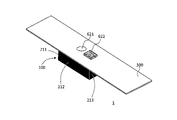
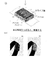
- FIG. 2 is a diagram for explaining the wristwatch main body 100 of the wristwatch 1 according to the first embodiment and the display unit 200 formed on five surfaces of the wristwatch main body 100 except the lower surface facing the user's arm side at the time of use.
- FIG. 2A is a perspective view of the wristwatch main body 100
- FIG. 2B is a plan view showing the display unit 200 of the wristwatch 1 developed on five display units 210 to 214.
- FIG. 2C is a bottom view showing the display unit 200 of the wristwatch 1 expanded on the five display units 210 to 214.
- the configuration of the wristwatch 1 according to the first embodiment will be described with reference to FIGS. 1 and 2.
- the wristwatch 1 according to the first embodiment has a rectangular parallelepiped wristwatch body 100 and five surfaces (upper surface and four side surfaces) excluding the lower surface facing the user's arm side at the time of use among the six surfaces constituting the surface of the wristwatch body 100.
- a display control unit (display) that controls the display of each of the five display units 210 to 214 formed over the entire area of the above, the belt 300 for attaching the wristwatch 1 to the user's arm, and the five display units 210 to 214.
- the control unit will be described later with reference to FIG. 3), and a detection unit for detecting the position information of the wristwatch 1.
- the belt 300 is not an essential configuration for the wristwatch 1, but a configuration suitable for the wristwatch 1.
- the detection unit is an image of the eyes of the user of the wristwatch 1 captured by the two image pickup elements 50, 60 installed at any part of the wristwatch 1 and the two image pickup elements 50, 60.
- a calculation unit for extracting information regarding the positional relationship between the eyes of the user of the wristwatch 1 and the wristwatch 1 is provided.
- the detection unit can detect information regarding the positional relationship between the eyes of the user of the wristwatch 1 and the wristwatch 1.
- the display control unit has a function of controlling the display of each of the five display units 210 to 214 based on the information detected by the detection units 50 and 60.
- at least one "information" in this application may be read as "data”.
- the image pickup devices 50 and 60 are preferably arranged at two corners on the upper surface of the rectangular parallelepiped wristwatch body 100, which are closer to the user under normal use conditions. ..
- the image pickup devices 50 and 60 may be arranged at other corners on the upper surface of the wristwatch body 100.
- one, three or four or more image pickup devices may be arranged on the wristwatch main body 100 or the belt 300.
- the image pickup element examples include a CCD (Charge Coupled Devices) image sensor or a CMOS (Complementary Metal Oxide Semiconductor) image sensor.
- the lens of the image pickup element is preferably capable of taking a wide-angle image centering on the image pickup element.
- "formed over the entire area" is sufficient as long as it appears to be formed over the entire area from the user's point of view, and may not be formed over the entire area in a strict sense. Therefore, even if there is an undisplayable gap between the display units 210 to 214, it is included in the category of "formed over the entire area".
- the wristwatch main body 100 has a rectangular parallelepiped having a predetermined thickness t, and has an upper surface 110 and four side surfaces (first side surface 111, second side surface 112, opposite to the lower surface).
- five display units 210 to 214 are formed on the five surfaces of the third side surface 113 and the fourth side surface 114).
- the display unit formed on the upper surface 110 of the wristwatch body 100 is referred to as the upper surface display unit 210
- the display unit formed on the first side surface 111 of the wristwatch body 100 is the first side surface display unit.
- the display unit formed on the second side surface 112 of the wristwatch body 100 is the second side surface display unit 212
- the display unit formed on the third side surface 113 of the wristwatch body 100 is the third side surface display unit 213.
- the display unit formed on the fourth side surface 114 of the main body 100 is referred to as the fourth side surface display unit 214.
- the five display units 210 to 214 are composed of five organic EL (Electroluminescence) display sheets. That is, the upper surface display unit 210 is made of an organic EL display sheet for the upper surface, the first side surface display unit 211 is made of the organic EL display sheet for the first side surface, and the second side surface display unit 212 is made of the organic EL display sheet for the second side surface.
- the third side surface display unit 213 is made of an organic EL display sheet for the third side surface, and the fourth side surface display unit 214 is made of an organic EL display sheet for the fourth side surface.
- first side surface display unit 211 When the first side surface display unit 211, the second side surface display unit 212, the third side surface display unit 213, and the fourth side surface display unit 214 are collectively or individually described, they are referred to as “side display units 210 to 214". It may be written.
- each organic EL display sheet is referred to as an organic EL display sheet 210 for the upper surface and an organic EL display sheet for the first side surface.
- the same reference numerals as those of the five display units 210 to 214 are used, such as 211, the organic EL display sheet 212 for the second side surface, the organic EL display sheet 213 for the third side surface, and the organic EL display sheet 214 for the fourth side surface. ..
- the top surface organic EL display sheet 210, the first side surface organic EL display sheet 211, the second side surface organic EL display sheet 212, the third side surface organic EL display sheet 213, and the fourth side surface organic EL display sheet 214 When they are collectively described, they may be expressed as "each organic EL display sheet 210 to 214". Further, when the organic EL display sheet 211 for the first side surface, the organic EL display sheet 212 for the second side surface, the organic EL display sheet 213 for the third side surface, and the organic EL display sheet 214 for the fourth side surface are collectively described, the organic EL display sheet 211 for the first side surface and the organic EL display sheet 214 for the fourth side surface will be described together. It may be expressed as "each side organic EL display sheet 211 to 214".
- Each of these organic EL display sheets 210 to 214 has a top surface 110 and four side surfaces (first side surface 111, second side surface 112, third side surface 113 and fourth side surface 114) of the wristwatch body 100, that is, a total of five. It is pasted against the surface. As a result, the wristwatch 1 as shown in FIG. 1 is configured. It should be noted that FIG. 1 shows a state in which the analog time is displayed, but when nothing is displayed, the five surfaces except the lower surface of the wristwatch main body 100 are blank over the entire area.
- the term "no pattern" here means that not only the analog clock display but also the digital clock display and various displays are not performed.
- each organic EL display sheet 210 to 214 is attached to the wristwatch body 100 one by one to form the display unit 200. By doing so, the wristwatch 1 is formed.
- the corners can be at right angles, and the flat surfaces of the organic EL display sheets 210 to 214 can be formed at right angles. The degree can be increased, which makes it look simple and comfortable.
- each organic EL display sheet 210 to 214 is used on the five sides of the wristwatch body 100, that is, the upper surface 110 and the four side surfaces (first side surface 111, second side surface 112, third side surface 113 and fourth side surface 114).
- the first electrode group 120 for supplying electric power and electric signals is exposed and provided.
- a second electrode group 220 for receiving electric power and an electric signal from the first electrode group 120 is provided at a position corresponding to the first electrode group 120. ing.
- the electrodes corresponding to the first electrode group 120 of the wristwatch body 100 and the second electrode group 220 of each of the organic EL display sheets 210 to 214 are electrically connected to each other.
- a drive circuit for supplying an electric signal for controlling the lighting state of each pixel of each of the organic EL display sheets 210 to 214 is provided.
- the drive circuit is not shown.
- FIG. 3 is a diagram showing a configuration of a control system for operating the wristwatch 1 according to the first embodiment as a functional block diagram.
- the functional block diagram shown in FIG. 3 shows mainly the functional blocks necessary for displaying among the various functions of the wristwatch 1 according to the first embodiment.
- a display image selection unit as a user interface that allows the user to select what kind of display is to be displayed on the five display units 210 to 214 (each organic EL display sheet 210 to 214).
- Each of the image data storage unit 420 storing the image to be displayed on the organic EL display sheets 210 to 214 and the image to be displayed on the organic EL display sheets 210 to 214 are interlocked or related images.
- the synchronization signal generation unit 430 that generates a synchronization signal for synchronizing between the organic EL display sheets 210 to 214, the time data generation unit 440 that generates the current time data, and the organic EL display sheets 210 to 214.
- the images displayed on the organic EL display sheets 210 to 214 may be images stored in the image data storage unit 420, images generated by an image data generation unit (not shown), or from the outside. It may be an image received via communication. For example, an image from the user's smartphone or an image from a contracted video distribution company may be displayed on the organic EL display sheets 210 to 214.
- the drive circuit 510 of the organic EL display sheet 210 for the upper surface the drive circuit 511 of the organic EL display sheet 211 for the first side surface, the drive circuit 512 of the organic EL display sheet 212 for the second side surface, The drive circuit 513 of the organic EL display sheet 213 for the third side surface and the drive circuit 514 of the organic EL display sheet 214 for the fourth side surface are provided.
- a power supply unit for supplying electric power to each functional block shown in FIG. 3 is also provided on the wristwatch main body 100 side, and the electric power from the power supply unit and Various signals from the display control unit 450 are provided on the first electrode group 120 (see FIG. 2A) provided on the wristwatch main body 100 side and on each organic EL display sheet 210 to 214 side, respectively. It is supplied via the second electrode group 220 (see FIG. 2C).
- the display control unit 450 reads out the image stored in the image data storage unit 420 based on the content selected by the user from the display image selection unit 410, and displays the read image on the organic EL display sheets 210 to 214. Control to make it. At this time, the display control unit 450 controls the display of each of the organic EL display sheets 210 to 214 so that the images to be displayed on each of the organic EL display sheets 210 to 214 are interlocked or related.
- the display control unit 450 controls to display the image read from the image data storage unit 420 on the organic EL display sheets 210 to 214, but at the time of starting the wristwatch 1 according to the first embodiment, the display control unit 450 controls. , Controls to display the display image selection screen that functions as the display image selection unit 410. By displaying the display image selection screen on the wristwatch 1, the user can select the content to be displayed from the displayed display image selection screen. Then, the display control unit 450 controls the display based on the display mode selected by the user. The display image may be selected from the selection screen of the user's smartphone linked with the wristwatch 1.
- the display control unit 450 is set to the analog clock display mode.
- the current time data is read from the time data generation unit 440, and the drive circuits 510 to 514 of the organic EL display sheets 210 to 214 are displayed so that the current time by the hour and minute hands is displayed on the organic EL display sheets 210 to 214.
- the display image may be selected from the selection screen of the user's smartphone linked with the wristwatch 1. A specific method of displaying the time in the analog time display mode will be described later.
- At least the display control unit 450 and the calculation unit 460 among the components constituting the control system of the watch body 100 are represented by a CPU (Central Processing Unit: central processing unit) and a GPU (Graphics Processing Unit: image processing unit).
- Various processes are executed according to the operation of the processing device. The various processes are performed, for example, while reading a computer program stored in a memory (ROM, RAM, EEPROM, etc.) in the wristwatch main body 100.
- the image data storage unit 420 is also a memory.
- the memory for storing the computer program may be the image data storage unit 420 or another storage unit.
- at least one drive circuit among the various drive circuits 510 to 514 of the display unit 200 may include a processing device typified by the above-mentioned CPU or GPU.
- each of the organic EL display sheets 210 to 214 is attached to each of the five surfaces excluding the lower surface among the six surfaces constituting the surface of the wristwatch main body 100. That is, the upper surface organic EL display sheet 210 is attached to the upper surface 110 of the wristwatch body 100, and the first side surface organic EL display sheet 211 is attached to the first side surface 111 of the wristwatch body 100 to display the organic EL for the second side surface.
- the sheet 212 is attached to the second side surface 112 of the wristwatch body 100, the organic EL display sheet 213 for the third side surface is attached to the third side surface 113 of the wristwatch body 100, and the organic EL display sheet 214 for the fourth side surface is a wristwatch.
- the organic EL display sheets 210 to 214 are attached to the corresponding surfaces of the wristwatch body 100 in this way, the organic EL display sheets are placed between the adjacent organic EL display sheets at the corners of the wristwatch body 100. There may be a gap corresponding to the thickness of.
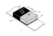
- FIG. 4 is a diagram shown for explaining how to deal with the gap generated between the adjacent organic EL display sheets.
- FIG. 4 is a diagram showing, for example, a gap generated between the organic EL display sheet 210 for the upper surface and the organic EL display sheet 213 for the third side surface.
- Black member 280 is embedded.
- the black member 280 for example, a silicone rubber mixed with a graphite filler to make it black can be used.
- the space between the top surface organic EL display sheet 210 and the third side surface organic EL display sheet 213 is shown in FIG. 4, the space between the five display units 210 to 214, that is, the first side surface is shown.
- the organic EL display sheet 211 for the second side surface and the organic EL display sheet 212 for the second side surface Between the organic EL display sheet 211 for the second side surface and the organic EL display sheet 212 for the second side surface, between the organic EL display sheet 212 for the second side surface and the organic EL display sheet 213 for the third side surface, and the organic EL display for the third side surface.
- Between the sheet 213 and the organic EL display sheet 214 for the fourth side surface between the organic EL display sheet 214 for the fourth side surface and the organic EL display sheet 211 for the first side surface, and the organic EL display sheet 210 for the upper surface, respectively.
- the gap between the side organic EL display sheets 211 to 214 is also filled with the black member 280.
- the black member 280 is embedded in the corner of the wristwatch body 100, that is, between the adjacent organic EL display sheets. Then, on the surface of each of the organic EL display sheets 210 to 214 in a state where the black member 280 is embedded between the adjacent organic EL display sheets, the protective member 290 so as to cover the entire of the organic EL display sheets 210 to 214. (See FIG. 6) is coated and cured.
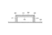
- FIG. 5 is a diagram for explaining a state in which the protective member 290 is applied and cured so as to cover the entire wristwatch 1.
- FIG. 5 is a cross-sectional view of the wristwatch body 100 obtained by vertically cutting the wristwatch body 100 from the organic EL display sheet 210 for the upper surface to the belt 300 on the lower surface in parallel with the long side of the rectangular parallelepiped wristwatch body 100.
- the components such as the display control unit 450 existing inside are not shown.
- a transparent protective member 290 is applied and applied so as to cover the entire five display units of the wristwatch 1, that is, the organic EL display sheet 210 for the upper surface and the organic EL display sheets 211 to 214 for each first side surface. It has been cured.
- the protective member 290 a silicone resin or the like having waterproofness, corrosion resistance and heat resistance can be preferably used.
- the transparent protective member 290 is applied and cured so as to cover the entire five display portions of the wristwatch 1, that is, the organic EL display sheet 210 for the upper surface and the organic EL display sheets 211 to 214 for each first side surface.
- the wristwatch 1 has waterproofness, corrosion resistance, and heat resistance and is not easily damaged, so that the wristwatch 1 becomes a highly reliable wristwatch.
- the above-mentioned five display units 210 to 214 may be composed of one organic EL display sheet (not shown). In that case, the one organic EL display sheet is bent along the outer shape of the wristwatch body 100 and attached to the wristwatch body 100.
- the five display units 210 to 214 are made of one organic EL display sheet, no gap is formed in the bent portion, so that the bent portion does not need to be filled with a black member.
- a gap corresponding to the thickness of the organic EL display sheet may be formed not at the bent portion but at the boundary portion of the adjacent organic EL display sheet.
- the organic EL display sheet for the upper surface existing in the center, the organic EL display sheet for the first side surface, the organic EL display sheet for the second side surface, the organic EL display sheet for the third side surface, and the organic EL display sheet for the fourth side surface, respectively.
- the organic EL display sheet for the upper surface is attached to the upper surface 110 of the watch body 100, and the organic EL display sheet for each side surface is bent.
- the organic EL display sheet for each side surface can be attached to each side surface 111 to 114 of the watch body 100.
- a gap corresponding to the thickness of the organic EL display sheet may be formed in the corner portion of each side surface display portion, and it is preferable to fill the gap with a black member.
- the wristwatch 1 according to the first embodiment can be worn on either the left or right arm of the user, but here, as shown in FIG. 1, the wristwatch 1 according to the first embodiment is worn on the wrist of the left arm of the user. The case where it is attached to the wristwatch will be described.
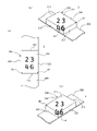
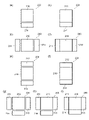
- FIG. 6 is a diagram shown for explaining the first display mode in the wristwatch 1 according to the first embodiment. For example, as shown in FIG. 6, it is assumed that 23:46 is displayed as the current time.
- FIG. 6A shows a time display when the wristwatch main body 100 is viewed from diagonally above near the image sensor 60.
- FIG. 6B shows a time display when viewed from above perpendicular to the surface of the organic EL display sheet 210 for the upper surface of the wristwatch body 100.
- FIG. 6C shows a time display when the wristwatch main body 100 is viewed from diagonally above the image sensor 50.
- the display units 210, 213, 214 display the time diagonally above the wristwatch body 100 so as to face the line of sight of the user near the image sensor 60.
- the surface composed of the display units 210, 213 and 214 is not a flat surface. Therefore, the numbers displayed across the two or three display units are displayed so as to be bent at the sides and corners of the display unit.
- the number “4” is displayed straddling the display unit 210 and the display unit 214.
- the number "6" is displayed straddling the display unit 210, the display unit 213, and the display unit 214. Therefore, the numbers "4" and "6" are displayed so as to be bent at the side where the display units are in contact with each other.
- the time is displayed only on the display unit 210 so as to face the line of sight of the user vertically above the upper surface of the wristwatch body 100. Since the time is displayed only on the display unit 210, four numbers without bending are displayed on the display unit 210.
- the display units 210, 212, and 213 display the time so as to face the line of sight of the user diagonally above the wristwatch body 100 and in a direction close to the image sensor 50. It will be done. Actually, the surface composed of the display units 210, 212, 213 is not a flat surface. Therefore, the numbers displayed across the two display units are displayed so as to be bent at the sides and corners of the display units. In FIG. 6 (c), the number "4" is displayed straddling the display unit 210, the display unit 212, and the display unit 213. Further, the number "6” is displayed straddling the display unit 210 and the display unit 212. Therefore, the numbers "4" and "6" are displayed so as to be bent at the side where the display units are in contact with each other.
- processing such as taking an image including the human eye by the image pickup devices 50 and 60 and recognizing the image by the calculation unit 460 is performed.
- the details of the above processing will be described later.
- the second display mode Next, the second display mode will be described. It is assumed that the user has selected the analog clock display mode from the display image selection unit 410. As a result, the five display units 210 to 214 display the outer edge of the clock, a total of four numbers indicating 12 o'clock, 3 o'clock, 6 o'clock and 9 o'clock, a short hand (hour hand) and a long hand (minute hand).
- FIG. 7 is a diagram shown for explaining a second display mode in the wristwatch 1 according to the first embodiment. For example, as shown in FIG. 7, it is assumed that 10:10 is displayed as the current time.
- FIG. 7A shows a time display when the wristwatch main body 100 is viewed from diagonally above near the image sensor 60.
- FIG. 7B shows a time display when viewed from above perpendicular to the surface of the organic EL display sheet 210 for the upper surface of the wristwatch body 100.
- FIG. 7C shows a time display when the wristwatch main body 100 is viewed from diagonally above the image sensor 50.
- the display of the analog clock indicating 10:10 should face the user as much as possible. It is displayed on at least one display unit of the display units 210 to 214.
- the display units 210, 213, 214 display the analog clock diagonally above the wristwatch body 100 so as to face the line of sight of the user near the image sensor 60. ..
- the surface composed of the display units 210, 213 and 214 is not a flat surface. Therefore, the display of the analog clock is displayed in a bent state at the side which is the boundary of each display unit 210, 213, 214. In FIG. 7A, a part of the lower region of the analog clock is displayed on the display unit 213 and the display unit 214.
- the analog clock is displayed only on the display unit 210 so as to face the line of sight of the user vertically above the upper surface of the wristwatch body 100. Since the analog clock is displayed only on the display unit 210, it is displayed on the display unit 210 without bending.
- the display units 210, 212, and 213 display the analog clock diagonally above the wristwatch body 100 so as to face the line of sight of the user near the image sensor 50.
- the surface composed of the display units 210, 212, 213 is not a flat surface. Therefore, the display of the analog clock is displayed in a bent state at the side which is the boundary of each display unit 210, 212, 213.
- a part of the lower region of the analog clock is displayed on the display unit 212 and the display unit 213.
- processing such as taking an image including the human eye by the image sensors 50 and 60 and image recognition by the arithmetic unit 460 is performed. Will be. The details of the above processing will be described later.
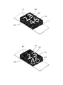
- FIG. 8 is a diagram shown for explaining a third display mode in the wristwatch 1 according to the embodiment.
- the third display mode of the wristwatch 1 according to the embodiment is also a mode in which the five display units 210 to 214 are set to the analog clock display mode, as in the second display mode described above.
- the numbers representing the time are set to 12 types from "1" to "12”, and these are the organic ELs for each side surface on each side surface of the wristwatch body 100. It is displayed on the display sheets 211 to 214.
- the display unit 210 displays dots corresponding to 12 kinds of numbers representing the time (indicated by M in FIG. 8) on the circumference of an ellipse or a rectangle, and has an hour hand 230 and a minute hand 240 inside thereof. it's shown.
- the time is 1:43.
- the display control unit 450 indicates the time in the analog clock display mode so that the inside of the wristwatch main body 100 can be seen through from the user's point of view.
- the numbers are controlled to be displayed on the side display units 211 to 214.
- the display control unit 450 displays the numbers representing the time in reverse left and right on the side surface that cannot be visually recognized by the user, and the numbers displayed in reverse left and right can be seen through the inside of the wristwatch body 100. Display processing like this is performed.
- the display mode is not such that the display of the time or the clock faces the user, and a number that should not be visible to the user is used. Using the side that can be seen by the person, it is displayed as if it were transparent. Such a display may be referred to as a display in which a stereoscopic image can be seen on the portion of the wristwatch body 100.
- controlling the display of each of the organic EL display sheets 210 to 214 so that the inside of the wristwatch body 100 can be seen through is to control the display as if the wristwatch body 100 is a transparent container. be.
- the user can visually recognize the inner side surface of the wristwatch body 100 (the inner side surface 111a of the first side surface 211 and the inner side surface 112a of the second side surface 212).
- the display is controlled so that the inner bottom surface 115a of the wristwatch body 100 can be visually recognized by the user.
- the "transparent container” in this case may be a colorless and transparent container or a colored transparent container having light transmission.
- the inside of the wristwatch body 100 can be seen through from the user's point of view.
- the individual numbers are displayed in reverse left and right when viewed from the user. Therefore, the user feels as if the wristwatch body 100 is a transparent container and the inside of the wristwatch body 100 can be seen through.
- the hour hand 230 and the minute hand 240 are displayed on the upper surface display unit 210 which looks transparent to the user.
- the minute hand 240 is displayed only on the upper surface display unit 210, it may be extended and displayed on one side surface display unit of the side surface display units 211 to 214.
- the display mode shown in FIG. 8A shows the time display when the wristwatch main body 100 is viewed from diagonally above the image sensor 60.
- Such a display mode can be realized because it is specified from which direction the user is looking at the wristwatch body 100. Therefore, using the image pickup devices 50 and 60 and the calculation unit 460, processing such as taking an image including the human eye and image recognition is performed. By such a process, a side surface invisible to the user is specified in the wristwatch main body 100, and the transparent display of the side surface can be pseudo-displayed on the upper surface or the side surface visible to the user.
- FIG. 8B shows a time display when viewed from above, which is slightly tilted backward along the belt 300 with respect to the surface of the organic EL display sheet 210 for the upper surface of the wristwatch body 100.
- the side display unit 213 is visible to the user, a normal display mode may be used.
- the side display units 212 and 214 are completely invisible to the user, there is no need to perform any display processing.
- Such a display can be realized by using the image pickup devices 50 and 60 and the calculation unit 460 as in the case of FIG. 8A.
- FIG. 8C shows a time display when the wristwatch main body 100 is viewed from diagonally above near the image sensor 50.
- the user uses the display control unit 450 on the inner side surface of the wristwatch body 100 (the inner side surface 111a of the first side surface 211 and the inner side surface 114a of the fourth side surface 214).
- the display units 210, 212, and 213 are controlled so that they can be visually seen transparently and the inner bottom surface 115a of the wristwatch body 100 can also be visually seen transparently from the user.
- Such a display can be realized by using the image pickup devices 50 and 60 and the calculation unit 460 as in the case of FIG. 8A.
- the wristwatch 1 is a wristwatch having a new value that has never existed before.
- the side that cannot be seen by the user it is possible not to display the numerical value or other display indicating the time in the analog clock display mode, but it does not give a sense of discomfort when a person other than the user sees the watch.
- a person other than the user may display the numerical value indicating the time correctly on the left and right. The details of the above processing will be described later.
- FIG. 9 is a diagram for explaining a fourth display mode in the wristwatch 1 according to the first embodiment.
- the fourth display mode is a mode in which the five display units 210 to 214 are set to the digital clock display mode.
- the digital clock display mode here does not mean that the time is represented by the hour hand and the minute hand, but means a display mode in which the time is displayed numerically as in the first display mode. Further, in the fourth display mode, an example of displaying not only the time but also the date, the day of the week, and other information will be described.
- the user selects, for example, "digital clock display” from the display image selection screen that functions as the display image selection unit 410, so that the five display units 210 to 214 can be displayed. It can be set to the digital clock display mode.
- the top display unit 210 sets the current time such as 10:25:34 to “10: In addition to displaying "25:34", today's date such as October 1, 2020 can be displayed as "20.10.01", and today's day of the week can be displayed as "Thursday”. Further, as other information, for example, today's weather forecast is displayed on each side display unit 211 to 214 (side surface in the example of FIG. 9) by a weather mark or the like. It should be noted that these various types of information can also be displayed so as to flow on each display unit. As an example, it is also possible to display the day of the week in a flowing manner so that various information is displayed one after another after the day of the week.
- the fourth display mode does not display the time or the like facing the user.
- the display form is rotated in units of 90 degrees in the plane of the display unit 210 so that the user can see the display such as the time in a horizontal writing state as much as possible, and the display of the weather is displayed.
- This is a mode in which the time is displayed on the side surface located directly below the display surface such as the time.
- FIG. 9A shows a time display when the wristwatch main body 100 is viewed from diagonally above near the image sensor 60.
- a display mode can be realized because it is specified from which direction the user is looking at the wristwatch body 100. Therefore, using the image pickup devices 50 and 60 and the calculation unit 460, processing such as taking an image including the human eye and image recognition is performed.
- the time and the like are displayed so as to be substantially parallel to the long side of the rectangular display unit 210 and to be normally visually recognized without being turned upside down. This is because the display parallel to the long side is easier for the user to see than the display parallel to the short side.
- the weather is displayed on the display unit 214 located directly below the display such as the time on the display unit 210.
- the display control unit 450 uses the image pickup elements 50 and 60 and the calculation unit 460 to direct the line of sight of the user to the display unit 210 of the wristwatch 1. Is specified, and the display mode such as the time on the display units 210 to 214 is determined. The details will be described later.
- FIG. 9B shows a time display when viewed from above, which is slightly tilted backward along the belt 300 with respect to the surface of the organic EL display sheet 210 for the upper surface of the wristwatch body 100.
- the rectangular display unit 210 displays the time and the like substantially parallel to the short side of the display unit 210.
- the processing of the display control unit 450 and the like is the same as in the case of FIG. 9A.
- FIG. 9C shows the time display when the wristwatch main body 100 is viewed from diagonally above near the image sensor 50. Similar to the cases of FIGS. 9A and 9B, the image pickup devices 50 and 60 and the calculation unit 460 are used to perform processing such as image capture and image recognition of an image including the human eye. As a result, in the line of sight of the user, the time and the like are displayed so as to be substantially parallel to the long side of the rectangular display unit 210 and to be normally visually recognized without being turned upside down. The weather is displayed on the display unit 212 located directly below the display such as the time on the display unit 210.
- the display control unit 450 uses the image pickup elements 50 and 60 and the calculation unit 460 to direct the line of sight of the user to the display unit 210 of the wristwatch 1. Is specified, and the display mode such as the time on the display units 210 to 214 is determined. The details of the above processing will be described later.
- various information including the digital clock display can be displayed as images by using the five display units 211 to 214, and some information (images) or all of them can be displayed. It is also possible to display information (images) in a flowing manner.
- the wristwatch 1 according to the first embodiment can realize an image display according to the line of sight of the user, and thus can be a wristwatch having a new value that has never existed before.
- FIG. 10 is a diagram for explaining a method for specifying a direction in which the user of the wristwatch 1 according to the first embodiment looks at the wristwatch 1.
- the wristwatch 1 according to the first embodiment uses two image pickup devices 50 and 60 and a calculation unit 460 to specify the distance and direction between the user's eye and the in-plane center of the display unit 210 of the wristwatch.
- FIG. 10A shows a three-dimensional space with the image sensor 60 (referred to as point A) as the origin, the display surface 210 as the XY plane, and the Z axis in the direction perpendicular to the display surface 210. It is assumed that the image pickup device 50 (referred to as point B) exists on the X-axis.
- the arithmetic unit 460 can recognize both eyes from the image of the user.
- the calculation unit 460 recognizes the positions of the human face and its eyes in the image by using the trained model in the image data storage unit 420. As a result, in the three-dimensional space, the direction D2 from the point A of the image sensor 60 to the midpoint M in the line segment connecting both eyes of the user is specified. However, only the direction D2 can be specified from the image taken by the image sensor 60.
- the calculation unit 460 can recognize both eyes from the image of the user, as in the case of the image taken by the image sensor 60.
- the use of the trained model is the same as in the analysis of the image captured by the image pickup device 60.
- the direction D3 from the point B of the image pickup device 60 to the midpoint M in the line segment connecting both eyes of the user is specified.
- the arithmetic unit 460 determines the coordinates of the point M where those directions intersect.
- the distance between the point A and the point B corresponds to the length of the short side of the display unit 210. Since the distance L2 between the point A and the point M, the distance L3 between the point B and the point M, and the directions D1 and D2 are also specified, the triangle ABM inclined at a certain angle from the display unit 210 can be specified.
- FIG. 10B is a diagram for explaining the direction and distance connecting the midpoint M of the line segment connecting both eyes of the user and the center C of the display unit 210.
- FIG. 10 (c) is a view of the wristwatch 1 omitted from FIG. 10 (b) and viewed from a position close to the wristwatch 1.
- the direction D4 from the point M toward the center C of the display unit 210 and the distance L4 between the MCs are also uniquely determined. This is because the positional relationship between the center C and the point A (or the point B) is fixed.
- the above calculation is performed by the arithmetic unit 460.
- the display control unit 450 of the wristwatch 1 transmits a signal to the drive circuits 510 to 514 to see the line of sight from the user. Display according to the direction.
- the distance L4 between MCs is not indispensable for performing display control by the display control unit 450 described above. It is sufficient if only the direction D4 from the point M toward the center C of the display unit 210 can be specified. However, by specifying the distance L4, the following merits can be enjoyed.
- the wristwatch 1 maintains a black state without displaying the wristwatch 1 when the distance L4 exceeds a certain threshold value (for example, 800 mm), while the wristwatch 1 maintains a black state when the distance L4 is equal to or less than the above threshold value (for example, 800 mm).
- the time can be controlled to be displayed on the display units 210 to 240 of the wristwatch 1.
- the threshold as described above is not limited to 800 mm and can be set to another distance such as 500 mm or 1200 mm.
- the threshold value may be stored in the image data storage unit 420, for example.
- the display control unit 450 or the calculation unit 460 can read the threshold value stored in the image data storage unit 420 and compare it with the distance L4 between the MCs.
- the threshold value may not be set by the user, or may be freely set by the user by using a setting means such as the display image selection unit 410.
- display / non-display may be switched according to the distance L2 + the distance L3.
- the eye position E1 or the eye position E2 may be used.
- the position of the detected one eye is specified instead of specifying the coordinates of the midpoint M.
- the triangle ABE2 (including the angle ⁇ formed by the triangle ABE2 and the display unit 210) may be specified.
- the above-described embodiment is an embodiment of the wristwatch 1 including a detection unit including two image pickup elements 50 and 60, but the number of image pickup elements is not limited to two.
- the detection unit includes one or more image pickup elements installed at any part of the wristwatch 1 and the user of the wristwatch 1 imaged by the one or more image pickup elements.
- a calculation unit may be provided for extracting information on the positional relationship between the user's eye of the wristwatch 1 and the wristwatch 1 from the image of the eye. As a result, the calculation unit can extract information on the positional relationship between the eyes of the user of the wristwatch 1 and the wristwatch 1 as the positional information of the wristwatch 1.
- the wristwatch 1 provided with only one image pickup element, although the direction from the user's eye toward a predetermined position of the upper surface display unit 210 of the wristwatch 1 (for example, the center of the upper surface display unit 210) can be specified, it is used.
- the distance between the human eye and the predetermined position of the upper surface display unit 210 cannot be specified.
- the direction of the image to be displayed on the display units 210 to 214 can be determined according to the above-mentioned direction.
- the direction and distance from the user's eye toward the predetermined position of the upper surface display unit 210 of the wristwatch 1 can be determined more accurately than the above-mentioned example using the two image pickup devices 50 and 60. Can be identified.
- One or more image pickup elements may be used as four image pickup elements.
- the four image pickup devices are preferably installed in the vicinity of the apex where the adjacent side surface of the four side surfaces of the wristwatch 1 and the upper surface of the wristwatch 1 are in contact with each other.
- the eye is used by using two image pickup elements other than the image pickup elements 50 and 60. The position of can be easily imaged.
- the four image pickup elements may be installed only on the belt 300 connected to the wristwatch 1, or may be separately installed in two at the connection portion between the wristwatch main body 100 and the belt 300.
- the image pickup is complemented as compared with the case where one image sensor is arranged at each of the four corners. Although the level is low, the complement level is high as compared with the case where the two image sensors 50 and 60 are arranged. Further, two of the three image pickup elements may be arranged at the two corners of the upper surface display unit 210, and the remaining one image pickup element may be arranged at the connection portion between the wristwatch main body 100 and the belt 300.
- FIG. 11 is a diagram showing a state in which the wristwatch 1 according to the second embodiment is attached to the left arm of the user.
- the arrow A indicates the direction of the line of sight when the user looks at the wristwatch 1 worn on the wrist of the left arm, as in the first embodiment.
- the direction of the arrow A is drawn on the horizontal plane, but the actual direction of the line of sight is generally diagonally downward from the user's eyes.
- the display units 210 to 214 are black in the non-display state, and the digital clock is displayed on the display units 210 to 214 in the display state.
- the display unit 210 displays a total of four numbers, that is, the number “2”, the number “3”, the number “4”, and the number “6” indicating 23:46.
- FIG. 12 is a diagram showing a configuration of a control system for operating the wristwatch 1 according to the second embodiment as a functional block diagram.
- the functional block diagram shown in FIG. 12 shows mainly the functional blocks necessary for displaying among the various functions of the wristwatch 1 according to the second embodiment.
- the detection unit provided in the wristwatch 1 according to the second embodiment includes a three-dimensional acceleration sensor that detects the attitude information of the wristwatch 1, and detects information on the three-dimensional attitude of the wristwatch 1 as the attitude information of the wristwatch 1. can do. Further, the detection unit is also a three-dimensional acceleration sensor that detects the motion information of the wristwatch 1, and can detect the information related to the three-dimensional motion of the wristwatch 1 as the motion information of the wristwatch 1.
- the functions peculiar to the second embodiment will be described with reference to FIG. 12, and the duplicated description of the functions common to the first embodiment will be omitted.
- the watch body 100 is further three-dimensional in addition to various components of the display image selection unit 410, the image data storage unit 420, the synchronization signal generation unit 430, the time data generation unit 440, and the display control unit 450, which are the same as those in the first embodiment. It includes an acceleration sensor (hereinafter, simply referred to as "acceleration sensor") 610. Each component of the display unit 200 is the same as that of the first embodiment.
- the acceleration sensor 610 is a kind of inertial sensor capable of measuring acceleration, and can detect three-dimensional inertial motion.
- the accelerometer 610 can detect the movement of the wristwatch 1 corresponding to the movement of the user's arm, and can also detect whether or not the display unit 210 of the wristwatch 1 holds a horizontal or near-horizontal angle.
- the accelerometer 610 also includes a calculation unit.
- the calculation unit is a part that performs calculations by a processing device such as a CPU or GPU. The same applies to the subsequent "calculation unit".
- the wristwatch main body 100 may include a device in which an acceleration sensor 610 and a gyro sensor are integrated. Further, a geomagnetic sensor may be further provided.
- the image data storage unit 420 stores various image data, acceleration thresholds, and various computer programs.
- the display control unit 450 refers to the above threshold value in the image data storage unit 420, and displays units 210 to 214 depending on whether the acceleration of the wristwatch 1 does not exceed the threshold value or exceeds the threshold value according to the movement of the user's arm.
- the display in can be switched.
- FIG. 13 is a diagram for explaining a first display mode of the wristwatch 1 according to the second embodiment.
- the display state a before the detection is such that each number indicating the time is in a predetermined direction (number).
- the state b rotating in the direction of the arrow around the number) and the state c rotating in the direction opposite to the predetermined direction (see the direction of the arrow around the number) are alternately repeated.
- the display control unit 450 sets the current time 252 displayed on the display unit 210 or the like when the acceleration received from the acceleration sensor 610 exceeds the threshold value stored in the image data storage unit 420 in advance.
- Each drive circuit 510 to 514 is made to display the vibration of the four constituent numbers.
- the user selects, for example, "other display modes" from the display image selection screen that functions as the display image selection unit 410, and further, a plurality of “other display modes”. For example, select "time vibration pattern" from the options of.
- the vibration image of the numbers is stored in the image data storage unit 420.
- the four numbers constituting the current time 252 may vibrate while protruding from the display units 211 to 214 as well as the display unit 210.
- the image data storage unit 420 is a computer programmed to return the display to the original display state a when a predetermined time has elapsed from the time when the display in which the acceleration detected by the acceleration sensor 610 starts to vibrate the numerical value exceeds the threshold value.
- the display control unit 450 measures the passage of time from the start of vibration, and when a predetermined time (for example, 30 seconds) elapses, the display control unit 450 repeatedly displays the vibration display state of the display state b and the display state c according to the above computer program. Switch to the original display state a where the numbers do not vibrate.
- FIG. 14 is a diagram for explaining a second display mode of the wristwatch 1 according to the second embodiment.
- the second display mode is set by the user designating a mode from the display image selection unit 410.
- the current time 252 is displayed on the upper surface display unit 210 as an initial state, but for example, when acceleration is applied to the wristwatch 1 due to the movement of the user's arm, the present time 252 is triggered by the acceleration. It is a display mode in which the current time 252 moves steadily and protrudes to the side surface.
- the user selects, for example, "other display modes” from the display image selection screen that functions as the display image selection unit 410, and further, a plurality of “other display modes". For example, select "time display protrusion pattern" from the options of.
- the display control unit 450 presents the current time. A signal is sent to each drive circuit 510 to 514 so that the display mode in which the 252 moves is controlled, and the display of each of the five display units 210 to 214 is controlled.
- the current time 252 protrudes to the side surface which side surface may be projected out may be programmed in advance, or the organic EL sheet on the side surface visible to the user according to the inclination measured by the acceleration sensor 610.
- the display may be displayed so as to protrude.
- FIG. 15 is a diagram showing a series of movements in which the current time protrudes to one or more side display units of the side display units 211 to 214 in addition to the top display unit 210 in a pre-programmed display mode.
- the four numbers constituting the current time change the display mode from a to h in the figure while protruding not only the upper surface display unit 210 but also the four types of side surfaces.
- the program may be terminated, or it may return to a again and change to h.
- Such a display operation is based on the description of the computer program stored in the image data storage unit 420.
- FIG. 16 is a diagram for explaining a third display mode of the wristwatch 1 according to the second embodiment.
- the third display mode is a display mode in which a set of small balls 262 in a rectangular parallelepiped wristwatch body 100 physically behaves in response to the movement of the user's arm.
- small balls 262 gather and change to the time display. That is, in this display mode, as an initial state, a state in which small spheres 262 are dispersed and randomly moving in the rectangular parallelepiped wristwatch body 100 is displayed, and then, with the passage of time, the small spheres 262 gather on the upper surface. The state of configuring the current time 252 is displayed.
- the user selects, for example, "other display modes” from the display image selection screen that functions as the display image selection unit 410, and further, a plurality of “other display modes". For example, select "small ball pattern" from the options of.
- the acceleration sensor 610 detects the acceleration of the wristwatch body 100 and / or the tilt of the upper surface display unit 210 according to the movement of the user's arm
- the display control unit 450 often moves in the wristwatch body 100 based on the detection status.
- the display is such that the small ball 262 of the is moved.
- the small ball 262 may move, for example, with the passage of time, or with the movement of the user's arm.
- the display in which the small sphere 262 forms the current time 252 may be switched from the display of the random movement up to that point when the acceleration sensor 610 no longer detects the acceleration.
- the display control unit 450 receives the signal, reads out the computer program in the image data storage unit 420, and reads the small sphere 262. It is possible to switch to the display of the current time 252 using. Specifically, the display control unit 450 sends a signal to each drive circuit 510 to 514 so that the display mode as described above is possible, and controls the display of each of the five display units 210 to 214.
- FIG. 17 is a diagram for explaining a fourth display mode of the wristwatch 1 according to the second embodiment.
- the fourth display mode is an mode in which the frame itself of the wristwatch body 100 vibrates illusionally based on the acceleration at which the user looks at the wristwatch 1. That is, in the fourth display mode, as shown in FIG. 17, the current time 252 is displayed on the upper surface display unit 210 as an initial state, but when acceleration is applied to the wristwatch 1 due to, for example, the movement of the arm, the movement thereof.
- This is a display mode (an illusionary display mode) in which the pseudo wristwatch frame 264 seems to vibrate steadily inside the wristwatch 1.
- the user selects, for example, "other display modes” from the display image selection screen that functions as the display image selection unit 410, and further, a plurality of “other display modes”. For example, select “Pattern that vibrates” from the options of.
- the display control unit 450 controls the display of each of the five display units 210 to 214 so that the display mode as described above is possible.
- the image data storage unit 420 obtains a pseudo wristwatch frame 264 (consisting of a plurality of frames) that switches from the display of the current time 252 on the upper surface display unit 210, a predetermined threshold of acceleration, and a signal of acceleration exceeding the predetermined threshold. Contains a computer program for switching from the normal time display to the display of the pseudo wristwatch frame 264.
- the display control unit 450 When the display control unit 450 receives a signal of acceleration exceeding a predetermined threshold value from the acceleration sensor 610, the display control unit 450 reads out a computer program in the image data storage unit 420 and outputs a signal to each drive circuit 510 to 514, and the current time is 252. The display of is switched to the display of the pseudo watch frame 264. The data of each display image is read from the image data storage unit 420 by the display control unit 450.
- the computer program may switch from the display of the pseudo wristwatch frame 264 to the display of the original current time 252 when a predetermined time has elapsed after detecting the acceleration exceeding the predetermined threshold value.
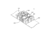
- FIG. 18 is a diagram for explaining a fifth display mode of the wristwatch 1 according to the second embodiment.
- the fifth display mode is a display mode in which a state in which the ribbon 254 is wound around the wristwatch 1 is displayed. In this display mode, it may be displayed that the ribbon 254 is wound or the wound ribbon 254 is unwound with the passage of time, for example, every second.
- the user selects, for example, "other display modes" from the display image selection screen that functions as the display image selection unit 410, and further, a plurality of "other display modes". For example, select "ribbon wrapping pattern" from the options of.
- the fifth display mode is a normal display mode when the acceleration detected by the acceleration sensor 610 exceeds a threshold value (referred to as a second threshold value) further larger than the predetermined threshold value in the first display mode to the fourth display mode.
- a threshold value referred to as a second threshold value
- the image data storage unit 420 changes from a normal time display to a ribbon-wrapping time display frame when a ribbon-wrapping type time display frame, a second threshold value of acceleration, and a signal of acceleration exceeding the second threshold value are obtained.
- a predetermined time for example, 3 minutes
- the ribbon-wrapping type time display frame is displayed to the original current time 252. You may switch.
- the display control unit 450 When the display control unit 450 receives a signal of acceleration exceeding the second threshold value from the acceleration sensor 610, the display control unit 450 reads out the computer program in the image data storage unit 420 and outputs a signal to each drive circuit 510 to 514, and the current time.
- the display of 252 is switched to the display of the ribbon-wrapping type time display frame.
- the data of each display image is read from the image data storage unit 420 by the display control unit 450.
- FIG. 19 is a diagram shown for explaining a modified example of the fifth display aspect of the wristwatch 1 according to the second embodiment.
- This modification is an example in which the ribbon 254 is wrapped around the wristwatch 1 while the current time 252 is displayed on the upper surface display unit 210.
- Such display control can be realized by the same control method as the above-mentioned control described with reference to FIG.
- the ribbon 254 is displayed to be wound in seconds while the current time 252 is not displayed, while the acceleration is the second.
- the two thresholds are exceeded, as shown in FIG. 19, it may be displayed that the ribbon 254 is wound in seconds while the current time 252 is displayed.
- FIG. 20 is a diagram shown for explaining the sixth display mode of the wristwatch 1 according to the second embodiment.
- the sixth display mode is a display mode in which fine particles 256 permeate from the upper surface to the bottom surface of the wristwatch 1.
- the surface color may be changed periodically so that fine particles 256 of another color permeate into the display mode.
- the user selects, for example, "other display modes" from the display image selection screen that functions as the display image selection unit 410, and further, a plurality of "other display modes". For example, select "Penetration pattern" from the options of.
- the wristwatch 1 is displayed according to the eighth display mode.
- the display of only the current time 252 up to that point is changed to the side display while the current time 252 is displayed on the upper surface display unit 210.
- This can be achieved by switching to a display in which fine particles 256 permeate into the portions 211 to 214 toward the bottom surface.
- the image data storage unit 420 changes from the normal time display to the display in which the fine particles 256 permeate when the moving image in which the fine particles 256 permeate, the second threshold value of the acceleration, and the signal of the acceleration exceeding the second threshold value are obtained.
- the computer program switches from the display in which fine particles 256 permeate to the display of the original current time 252 when a predetermined time (for example, 3 minutes) elapses after detecting the acceleration exceeding the second threshold value. You may do it.
- the display control unit 450 When the display control unit 450 receives a signal of acceleration exceeding the second threshold value from the acceleration sensor 610, the display control unit 450 reads out the computer program in the image data storage unit 420 and outputs a signal to each drive circuit 510 to 514, and the current time.
- the display of 252 is switched to the display in which fine particles 256 permeate.
- the display control unit 450 tells each drive circuit while reading the computer program having the above description in the image data storage unit 420. , Instruct the color change. Further, the data required for display is read from the image data storage unit 420 by the display control unit 450.
- FIG. 21 is a diagram for explaining a seventh display mode of the wristwatch 1 according to the second embodiment.
- the liquid is contained in the transparent container as if the user sees it, and the liquid is displayed to increase or decrease as it shakes in the transparent container.
- the user selects, for example, "other display modes" from the display image selection screen that functions as the display image selection unit 410, and further, a plurality of "other display modes". For example, select "liquid pattern" from the options of.
- the wristwatch 1 is displayed according to the eighth display mode.
- the image data storage unit 420 changes the form of the liquid 265 in the transparent container according to the data for displaying the liquid 265 in the transparent container, the signal from the acceleration sensor 610, and the passage of time, and the display unit 210 to Contains a computer program for display at 214.
- the display control unit 450 reads out the computer program in the image data storage unit 420 based on the signal received from the acceleration sensor 610, and outputs a signal to each drive circuit 510 to 514 to adjust the levelness and movement of the watch 1. Display the corresponding liquid 265.
- the liquid 265 is closer to the display unit 213 side. Further, since the wristwatch 1 moved in the direction of the thick arrow, the liquid 265 is displayed as wavy.
- the liquid 265 can be displayed so as to increase with the passage of the current time 252.
- Such a display is also realized by the control of the display control unit 450. That is, the display control unit 450 reads out the computer program in the image data storage unit 420 based on the time signal, outputs a signal to each drive circuit 510 to 514, and gradually discharges the liquid 265 according to the time. Display to increase.
- the display control unit 450 controls the change in the position of the liquid 265 in the wristwatch body 100 based on the acceleration from the acceleration sensor 610 and the change in the amount of the liquid 265 based on the time.
- both changes in the position and amount of the liquid 265 may be controlled to depend only on the time, not on the signal from the accelerometer 610. In that case, the liquid 265 appears to make a pre-programmed swaying motion in the transparent container and increase over time.
- both changes in the position and the amount of the liquid 265 may be controlled so as to depend only on the acceleration sent from the acceleration sensor 610 regardless of the time. In that case, the liquid 265 is displayed so as to sway in the transparent container according to the inclination and acceleration of the wristwatch body 100.
- FIG. 22 is a diagram for explaining an eighth display mode of the wristwatch 1 according to the second embodiment.
- the eighth display mode as shown in FIG. 22, different flows in the flow direction 266 are generated for each display surface (upper surface display unit 210 and four side display units 211 to 214), and the flow is, for example, It is a display mode that changes randomly every second.
- the current time 252 is also displayed on the upper surface display unit 210. However, it is not necessary to display the current time 252.
- Such a display mode is a mode in which high-speed flows in different directions are generated on each surface of the display units 210 to 214. That is, each surface is divided according to the direction of flow.
- the user selects, for example, "other display modes” from the display image selection screen that functions as the display image selection unit 410, and further, a plurality of "other display modes". For example, select "flow pattern" from the options of. As a result, the wristwatch 1 is displayed according to the eighth display mode.
- FIG. 22 shows an example in which the state a and the state b are repeated every second as the flow display mode.
- the switching of the display between the state a and the state b is not limited to every 1 second, and can be arbitrarily changed to every 2 seconds or every 10 seconds.
- the display control unit 450 controls the display units 210 to 214 to display the flow based on the time signal.
- the flow image is stored in the image data storage unit 420.
- the display control unit 450 reads out an image of the flow in the image data storage unit 420 while reading out the computer program in the image data storage unit 420, outputs a signal to each drive circuit 510 to 514, and displays the image. ..
- the flow display mode may change based on the signal from the acceleration sensor 610.
- the image data storage unit 420 randomly selects one type from the image data of a plurality of types of flows, the threshold value of the acceleration when switching the flow image, and the images of the plurality of types of flows when the acceleration exceeds the threshold value.
- the display control unit 450 randomly selects flow image data from the image data storage unit 420 and sends a signal to the drive circuits 510 to 514. Put out and switch from the display of the image of the current flow to the display of the image of the new flow.
- the wristwatch 1 can execute or change the display of the display units 210 to 214 by using the information from the acceleration sensor 610, so that the wristwatch 1 has a new value that has never existed before. be able to.
- the detection unit provided in the watch 1 according to the third embodiment is a pulse meter (or heart rate monitor), a body temperature monitor, a sphygmomanometer, and a heart that detect health-related information (information including health information and fitness information) of the user of the watch 1. It is an electric meter or a three-dimensional acceleration sensor.
- the detection unit can detect information on the pulse (or heartbeat), body temperature, blood pressure, or activity of the user of the wristwatch 1 as health-related information of the user of the wristwatch 1.
- the "information about the activity” means the information about the behavior of the user.
- Information on activities includes information on how many steps you have walked, information on how many kilometers you have walked, information on how many floors you have gone up, information on how many calories you have burned, information on how many hours you have been sitting on the chair, and how many hours in a row on the chair.
- FIG. 23 is a diagram showing a state in which the main part of the wristwatch 1 according to the third embodiment is viewed from the lower surface thereof.
- the surface other than the lower surface of the wristwatch 1 is common to the second embodiment (see FIG. 11).
- the belt 300 corresponding to the lower surface of the wristwatch body 100 has two through holes penetrating in the thickness direction of the belt 300.
- One of these through holes is a circular hole when viewed from the lower surface of the belt 300 (the upper surface in FIG. 23).
- the remaining one through hole is a rectangular hole.
- the light emitting / receiving unit 621 necessary for measuring blood pressure, pulse, and electrocardiogram is provided in the wristwatch body 100 and is exposed to the outside through the above-mentioned circular hole, and emits light toward the user's wrist. Allows light reception from the wrist direction.
- the body temperature measurement sensor 622 is a sensor having a rectangular parallelepiped shape provided in the wristwatch main body 100, and is exposed from the lower surface of the belt 300 through the rectangular hole.
- FIG. 24 is a diagram showing a configuration of a control system for operating the wristwatch 1 according to the third embodiment as a functional block diagram.
- the functional block diagram shown in FIG. 24 shows mainly the functional blocks necessary for displaying among the various functions of the wristwatch 1 according to the third embodiment.
- the functions peculiar to the third embodiment will be described with reference to FIG. 24, and duplicate description will be omitted for the functions common to each of the above-described embodiments.
- the watch body 100 has the same display image selection unit 410, image data storage unit 420, and synchronization signal generation unit 430 as in the second embodiment.
- a 660 which may be referred to as a sphygmomanometer
- a body temperature measuring unit which may be referred to as a sphygmomanometer
- the acceleration sensor 610, the blood pressure measuring unit 630, the pulse measuring unit 640, the electrocardiogram measuring unit 660, and the body temperature measuring unit 670 also include a calculation unit.
- the light emitting / receiving unit 621 includes, for example, a light emitting diode and a light receiving diode.
- the body temperature measurement sensor 622 is, for example, a high-sensitivity sensor that measures heat flux from the skin surface of the user's wrist.
- the value measured by the sensor is converted to the temperature at the center of the body using a specific algorithm.
- the display image selection unit 410 can also select any health-related information such as blood pressure measurement, pulse measurement, electrocardiogram measurement, and body temperature measurement.
- the wristwatch 1 can perform various displays according to the selection. Details of various displays will be described later.
- At least the display control unit 450, the acceleration sensor 610, the blood pressure measurement unit 630, the pulse measurement unit 640, the electrocardiogram measurement unit 660 and the body temperature measurement unit 670 of the watch body 100 perform various processes by the operation of the processing device represented by the CPU and GPU. Run. The various processes are performed, for example, while reading a computer program stored in a memory (ROM, RAM, EEPROM, etc.) in the wristwatch main body 100.
- the memory for storing the computer program may also serve as the image data storage unit 420, or may be a storage unit different from the image data storage unit 420.
- At least one drive circuit among the various drive circuits 510 to 514 of the display unit 200 may include a processing device typified by the CPU or GPU described above.
- the wristwatch 1 including a blood pressure monitor, a pulse meter, an electrocardiograph, and a thermometer as detection units will be described first with reference to the drawings. Next, the detection and display of information on activities (information including fitness information) using the three-dimensional accelerometer will be described.
- FIG. 25 is a diagram shown for explaining the first display mode of the wristwatch 1 according to the third embodiment.
- the first display mode is a mode in which the blood pressure of the user is displayed.
- FIG. 25A shows a display example when the blood pressure of the user is normal.
- FIG. 25B shows a display example when the blood pressure of the user deviates from the normal value, that is, when the blood pressure is abnormal.
- the user selects, for example, "other display modes” from the display image selection screen that functions as the display image selection unit 410, and further, a plurality of options in "other display modes". For example, select "Blood pressure measurement" from the list. This makes it possible to measure blood pressure.
- the blood pressure measurement unit 630 starts measuring the blood pressure after a predetermined time has elapsed (for example, 10 seconds later) from the user's selection instruction.
- a predetermined time for example, 10 seconds later
- light is emitted from the green light emitting diode in the light emitting / receiving unit 621 toward the user's wrist. This utilizes the mechanism by which blood reflects light with a green wavelength. The reflection of light differs between when the heart is pulsing and the blood flow in the blood vessels is high and when the blood flow is low.
- the blood pressure measuring unit 630 measures the blood pressure based on the difference in the reflection of the light.
- the blood pressure measuring unit 630 can control the light emission and the light reception to the light emitting / light receiving unit 621.
- the blood pressure measuring unit 630 sends the blood pressure data to the display control unit 450.
- the display control unit 450 reads out the image data for displaying the blood pressure in the image data storage unit 420 according to the computer program in the image data storage unit 420, sends a signal to each drive circuit 510 to 514, and displays units 210 to 214. To display the blood pressure.
- the blood pressure is visually displayed not only by the numbers of the systolic blood pressure and the diastolic blood pressure, but also by the display form 267 of the annulus region 268 and its internal region 269.
- the annulus region 268 and the internal region 269 are displayed within the range of the upper surface display unit 210.
- the annulus region 268 and / or the internal region 269 becomes large, and for example, it is displayed so as to protrude from the side display portions 212 and 214.
- both the systolic blood pressure and the diastolic blood pressure are abnormal values, as shown in FIG. 25 (b), both the annular region 268 and the internal region 269 are displayed so as to protrude from the side display portions 212 and 214.
- the display control unit 450 receives image data from the image data storage unit 420 according to the blood pressure received from the blood pressure measurement unit 630, and displays the image data on the display units 210 to 214 according to the blood pressure.
- the colors of the respective regions 268 and 269 may be changed without changing the sizes of the annular region 268 and the internal region 269.
- the color of each region 268,269 can be green or blue, and when the blood pressure is abnormal, the color of each region 268,269 can be red. Further, both the size change and the color change of each region 268,269 may be performed.
- FIG. 26 is a diagram for explaining a second display mode of the wristwatch 1 according to the third embodiment.
- the second display mode is a mode in which the pulse of the user is displayed.
- the user selects, for example, "other display modes" from the display image selection screen that functions as the display image selection unit 410, and further, a plurality of options in the "other display modes". For example, select "Pulse measurement” from the list. This makes it possible to measure the pulse.
- the pulse measurement unit 640 When the user selects the pulse measurement mode, the pulse measurement unit 640 emits light from the light emitting / receiving unit 621 after a lapse of a predetermined time (for example, 10 seconds) from the instruction of the user's selection, and the user's pulse measurement unit 640 emits light. Detect the pulse through the blood vessels in the wrist. Hemoglobin in blood has the property of easily absorbing green light.
- the light receiving diode receives the reflected light over time.
- the pulse measuring unit 640 calculates the pulse rate from the time change of the intensity of the reflected light.
- the pulse measuring unit 640 can control the light emission and the light reception to the light emitting / light receiving unit 621.
- the pulse measuring unit 640 sends the pulse data to the display control unit 450.
- the display control unit 450 reads out the image data for pulse display in the image data storage unit 420 according to the computer program in the image data storage unit 420, sends a signal to each drive circuit 510 to 514, and displays units 210 to 214. To display the pulse rate.
- the pulse display 270 of the display units 210 to 214 extends from the heart mark 271 displayed in the center of the upper surface display unit 210, for example, from the heart mark 271 to the side surface display units 211 to 214 via the upper surface display unit 210.
- the line 272 and the line 272 are provided.
- the heart mark 271 blinks according to the detected pulse.
- the line 272 starts displaying from the display unit 214, and is cumulatively displayed in the order of the display unit 213, the display unit 212, and the display unit 211 (see the direction of the arrow in FIG. 26).
- FIG. 27 is a diagram for explaining a third display mode of the wristwatch 1 according to the third embodiment.
- the third display mode is a display mode different from the second display mode, in which the display 285 at the time of pulse measurement is displayed on the display units 210 to 214.
- the user selects, for example, "other display modes” from the display image selection screen that functions as the display image selection unit 410, and further, a plurality of options in the "other display modes". For example, select "Pulse measurement 2" from the list. This makes it possible to measure the pulse as in the case described in the second display mode.
- the pulse measurement unit 640 emits light from the light emitting / receiving unit 621 after a predetermined time has elapsed (for example, 10 seconds later) from the instruction of the user's selection, and is used.
- a pulse is detected through a blood vessel in a person's wrist.
- the display control unit 450 reads out the image data for pulse display in the image data storage unit 420 according to the computer program in the image data storage unit 420.
- a signal is sent to each drive circuit 510 to 514 to cause the display units 210 to 214 to display the pulse.
- the third display mode it is possible to log the change of the pulse on the time axis in the side display units 211 to 214.
- the display 285 at the time of pulse measurement is different from the pulse display in the second display mode.
- the display 285 includes, for example, an information display 286 regarding music on the top display unit 210 and a visualizer display 287 as pulse information on the side display units 211 to 214, which is executed together with the reproduction of music. This display 287 moves in response to the pulse. If the user sets a favorite song in advance, the display control unit 450 can also select and play the song. Music can be selected from the image data storage unit 420 or a server on the cloud.
- the display 285 does not necessarily have to be accompanied by music reproduction. For example, in addition to the normal time display on the upper surface display unit 210, only the change in pulse rate may be displayed on the side surface display units 211 to 214.
- the display 285 may be performed when the pulse is measured during the reproduction of music. Strictly speaking, the pulse and the heart rate are different, but the heart rate may be measured instead of the pulse measurement. In that case, for example, it is preferable to obtain the heartbeat signal from near the heart.
- the wristwatch 1 may be provided with a sensor capable of detecting vibration during a heartbeat, and the sensor may be attached near the heart to send heartbeat information to the wristwatch 1.
- the user selects, for example, "other display mode” from the display image selection screen that functions as the display image selection unit 410, and further, the user selects "other display mode". For example, select “electrocardiogram measurement” from the plurality of options. This makes it possible to measure the electrocardiogram.
- the electrocardiogram measuring unit 660 measures the electrocardiogram by the light emitting / receiving unit 621 after a predetermined time has elapsed (for example, 10 seconds later) from the instruction of the user's selection.
- the electrocardiogram measuring unit 660 captures the change over time of the reflected light obtained by emitting light from the light emitting / receiving unit 621 toward the blood vessel and converts it into a waveform, as in the case of heartbeat measurement.
- the display control unit 450 receives the waveform display data from the electrocardiogram measurement unit 660, and reads out the image data for electrocardiogram display in the image data storage unit 420 according to the computer program in the image data storage unit 420.
- the display control unit 450 subsequently sends a signal to the drive circuits 510 to 514 to cause the display units 210 to 214 to display the electrocardiogram.
- the waveform of the electrocardiogram can be displayed over time on at least one of the side display units 211 to 214 in FIG. 27.
- the electrocardiogram may be measured by providing an electrode on the lower surface of the wristwatch or belt and electrically passing through the electrode.
- the pulse measuring unit 640 and the light emitting / receiving unit 621 detect and display the user's heartbeat. It can be displayed on the display units 210 to 214 by the control unit 450. This is because it is possible to detect a sudden increase in the heart rate at the time of waking up and a sudden decrease in the heart rate at the time of bedtime.
- the third display mode instead of displaying "change on the time axis of the pulse” on the side display units 211 to 214, "on the time axis of the sound pressure level" as beat information of the music being played. It is also possible to display "change of".
- FIG. 28 is a diagram for explaining a fourth display mode of the wristwatch 1 according to the third embodiment.
- the fourth display mode is a mode in which the display 295 of the user's body temperature is displayed on the display units 210 to 214.
- the user selects, for example, "other display modes" from the display image selection screen that functions as the display image selection unit 410, and further, a plurality of options in "other display modes". For example, select "body temperature measurement” from the list. This makes it possible to measure body temperature.
- the body temperature measuring unit 670 measures the body temperature by the body temperature measuring sensor 622 after a predetermined time has elapsed (for example, 10 seconds later) from the instruction of the user's selection.
- the body temperature measuring unit 670 receives the body temperature data from the body temperature measuring sensor 622 and sends the data to the display control unit 450.
- the display control unit 450 reads out the image data for displaying the body temperature in the image data storage unit 420 according to the computer program in the image data storage unit 420, sends a signal to each drive circuit 510 to 514, and displays units 210 to 214. To display the body temperature 295.
- a band-shaped display unit 296 extending from the side surface display unit 212 to the side surface display unit 214 via the top surface display unit 210 displays a region 297 indicating the high or low body temperature.
- the area 297 extends from the lower side in the width direction of the side surface display unit 214 to the upper surface display unit 210 and is displayed.
- the region 297 extends from the upper surface display unit 210 toward the side surface display unit 212.
- the numerical value indicating the body temperature (in this example, the display of "36.5 ° C.”) is displayed on the band-shaped display unit 296 together with the region 297.
- the numerical value indicating the body temperature is not essential.
- the current time is not displayed on the upper surface display unit 210, the time may be displayed.
- the accelerometer 610 as a detection unit provided in the wristwatch 1 can also detect information about the activity of the user of the wristwatch 1. For example, information on how many steps have been taken and information on how many kilometers have been walked can be detected through the acceleration sensor 610. The number of steps taken and the distance can be displayed on the side display units 211 to 214 by changing the length according to the number of steps and the distance.
- the watch 1 uses the information from the acceleration sensor 610, the blood pressure measuring unit 630, the pulse measuring unit 640, the electrocardiogram measuring unit 660, and the body temperature measuring unit 670 to determine the health of the user. Since the fitness information and information on a wide range of activities including the fitness information can be displayed on the display units 210 to 214, it is possible to make a watch having a new value that has never existed before.
- Embodiment 4 of the present invention will be described.
- the same reference numerals may be given to the components common to each of the above-described embodiments, and the description thereof may be omitted.
- FIG. 29 is a diagram showing a configuration of a control system for operating the wristwatch 1 according to the fourth embodiment as a functional block diagram.
- the functional block diagram shown in FIG. 29 is a functional block required mainly for displaying and a sensor necessary for detecting the movement of the wristwatch 1 among various functions possessed by the wristwatch 1 according to the fourth embodiment. It is shown.
- the functions specific to the fourth embodiment will be described with reference to FIG. 29, and duplicate description will be omitted for the functions common to each of the above-described embodiments.
- the wristwatch body 100 is provided with various components of a display image selection unit 410, an image data storage unit 420, a synchronization signal generation unit 430, a time data generation unit 440, and a display control unit 450, which are the same as those of the above-described embodiments.
- a microphone 690 and a GPS (Global Positioning System) 700 are provided as a detection unit.
- At least the display control unit 450, the microphone 690, and the GPS 700 of the wristwatch main body 100 execute various processes by the operation of a processing device represented by a CPU and a GPU.
- the display on the display units 210 to 214 can be selected or changed by voice through the microphone 690.
- the microphone 690 also includes a calculation unit.
- the display image selection unit 410 enables selection of a mode for displaying and switching the display by inputting voice.
- the display control unit 450 receives voice data through the microphone 690, the display control unit 450 recognizes the voice and reads out specific image data according to a computer program in the image data storage unit 420. Subsequently, the display control unit 450 causes the display units 210 to 214 to display an image by the drive circuits 510 to 514.
- the GPS 700 As a detection unit, it is possible to display a specific display when the wristwatch 1 enters a specific position range. Further, in the wristwatch 1 according to the fourth embodiment, the current position of the user can be displayed on the display units 210 to 214 through the GPS 700.
- the GPS 700 also includes a calculation unit.
- the display image selection unit 410 enables selection of a mode for detecting the position of the user by the GPS 700.
- the display control unit 450 receives the user's position information data through the GPS 700, the display control unit 450 reads out specific image data (including map data) according to a computer program in the image data storage unit 420. Subsequently, the display control unit 450 causes the display units 210 to 214 to display an image showing the position of the user on the map by the drive circuits 510 to 514.
- FIG. 30 is a diagram shown for explaining the first display mode of the wristwatch 1 according to the fourth embodiment.
- the first display mode is a display mode in which a plurality of images 258 constituting the frame of the video are deposited from the present (top surface) to the past (bottom surface). Then, with the passage of time, the image closer to the present is displayed on the upper surface display unit 210 among the plurality of images 258. Further, the end faces 260 of the plurality of images 258 deposited are displayed on the four side surface display units 211 to 214. For example, a total of 1000 images are stored in the image 258, and the latest 100 of them are displayed on the display units 210 to 214 as if they are exposed and loaded on the belt 300.
- the newest image (No. 1000) 258 is displayed on the upper surface display unit 210.
- the image 258 at the bottom of the 100 images loaded is the 901st image counting from the oldest image 258.
- the oldest images 258 to 900 are not displayed on the display units 210 to 214, and are positioned as if they are buried below the wristwatch body 100. Further, the end faces 260 of the 100 images 258 are displayed on the side surface display units 211 to 214.
- the user selects, for example, "other display modes” from the display image selection screen that functions as the display image selection unit 410, and further, “other display modes". For example, select “video frame” from a plurality of options in.
- the microphone 690 receives the voice.
- the display control unit 450 analyzes the sound from the microphone 690 and turns over one image 258 from the image data storage unit 420 (the 999th image counted from the oldest image 258: No.999). ) Is read, a signal is sent to each drive circuit 510 to 514, and the image is displayed on the display units 210 to 214.
- the series of operations by the display control unit 450 is performed according to a computer program stored in the image data storage unit 420. In this way, No.
- the image 258 of 999 is displayed on the upper surface display unit 210.
- the end faces 260 of the 100 images 258 are displayed on the side surface display units 211 to 214.
- the display based on the voice emitted from the microphone 690 or the switching operation thereof can also be applied to the case of executing one or more display modes in each of the above-described embodiments.
- the numbers constituting the current time 252 may start to dance by instructing the microphone 690 to "dancing".
- the image data storage unit 420 stores image data for displaying the numbers constituting the current time 252 so as to start dancing based on the reception of the voice "dancing".
- the display control unit 450 reads out the image data in the image data storage unit 420 according to the computer program in the image data storage unit 420, sends a signal to each drive circuit 510 to 514, and displays numbers on the display units 210 to 214. Make a dance display.
- Such an example is the same for the other display modes of the above-mentioned embodiments 2 and 3.
- the display control unit 450 or the calculation unit of the microphone 690 is in the image data storage unit 420 according to the computer program in the image data storage unit 420 based on the audio data received wirelessly or by wire from the microphone of the smartphone.
- Image data can be read out and signals can be sent to the drive circuits 510 to 514 to cause the display units 210 to 214 to display the numbers dancing.
- FIG. 31 is a diagram for explaining a second display mode of the wristwatch 1 according to the fourth embodiment.
- the display unit 210 to 214 is obtained by the user selecting the GPS function mode from the display image selection unit 410 or emitting a voice such as "GPS activation" through the microphone 690. It can be displayed in.
- the display control unit 450 reads out the map image data in the image data storage unit 420 according to the computer program in the image data storage unit 420.
- the type of map image and the data of the user's current position are determined based on the radio waves received by the GPS 700 from a plurality of artificial satellites.
- the display control unit 450 When the display control unit 450 receives data from the GPS 700, it sends a signal to the drive circuits 510 to 514 to cause the display units 210 to 214 to display the map image 298 and the user's current position 299. Although the current time 252 is also displayed on the upper surface display unit 210, the current time 252 may not be displayed.
- the microphone 690 and the GPS 700 as detection units provided in the wristwatch 1 can be used alone or jointly to realize the detection and display of the following activity information. For example, "information about how many hours you have been sitting on a chair”, "information about how many hours you have been sitting on a chair continuously”, and "information about how many hours you have swam" can be easily detected by using the microphone 690 and GPS700. can.
- each sound of the start and end of the operation may be emitted to the microphone 690.
- the state of sitting on a chair or the state of continuing swimming can be known by detecting the position of the user with the GPS700.
- the wristwatch 1 can display the first display mode, the second display mode, and other display modes on the display units 210 to 214 by using the information from the microphone 690 and the GPS 700. It can be a wristwatch with new value that is not available.
- the display units 210 to 214 display the fifth display mode or the sixth display mode of the second embodiment. (See FIGS. 18-20).
- the display may be changed when the acceleration exceeds a preset second threshold value. For example, when the acceleration exceeds the second threshold value, the displayed object (number, liquid, etc.) may be moved faster than when the acceleration is within the range from the first threshold value to the second threshold value.
- a threshold value of 1 or 2 or more is set for the voice detected by the microphone 690, and when the decibel value of the voice exceeds a predetermined threshold value, the displayed object (number, liquid, etc.) is displayed. You may want to move faster.
- the image pickup device is provided on a wristwatch or a belt, but the present invention is not limited thereto. Even if an image sensor is provided on the user's glasses or sunglasses, information regarding the positional relationship between the user's eye of the wristwatch and the wristwatch can be detected from the image of the wristwatch captured by the image sensor. good.
- the present invention is the wristwatch 1
- the present invention is not limited to the wristwatch 1, and can be a wristwatch-type display device.
- the wristwatch-type display device has the same or similar form as the wristwatch 1, and refers to a device that does not display the time or a device that displays the time but whose main purpose is to display other than the time.
- the configuration can be the same as that of the wristwatch 1 described above, except for the time display. That is, in the wristwatch-type display device, the watch-type display device main body (corresponding to the wristwatch main body 100) of FIG.
- Each organic EL display sheet 210 to 214 as five display units formed over the entire surface of each surface, a display control unit 450 that controls the display of each of the five display units, and position information and posture of a wristwatch-type display device. It includes a detection unit that detects at least one of information, motion information, and user's health-related information.
- the display control unit 450 has a function of controlling the display of each of the five display units 210 to 214 based on at least one piece of information detected by the detection unit.
- the display control unit 450 has a function of controlling the display of each of the five display units 210 to 214 so that the images to be displayed on each of the five display units 210 to 214 are interlocked or related. For example, the display control unit 450 can control the display of each of the five display units 210 to 214 so that the inside of the wristwatch-type display device main body can be seen through from the user's point of view.
- the wristwatch-type display device of the present invention it is possible to display various images in various modes by using four side surfaces in addition to the upper surface of the rectangular parallelepiped wristwatch-type display device main body. .. Therefore, according to the wristwatch-type display device of the present invention, it is possible to provide a wristwatch-type display device having a new value that has never existed before.
- the wristwatch or the wristwatch type display device of the present invention may include all or a part of each component of the wristwatch 1 according to the first to fourth embodiments.
- the wristwatch or wristwatch-type display device according to the modification of the present invention includes the image pickup elements 50 and 60 and the calculation unit 460 of the wristwatch 1 according to the first embodiment, and the acceleration sensor 610 of the wristwatch 1 according to the second embodiment.
- all or part of the GPS 700 may be provided.
- the display by voice through the microphone of the smartphone or the switching thereof is not limited to the fourth embodiment, and other embodiments are also possible.
- the gap is made inconspicuous by embedding a black member in the gap formed between the five display units 210 to 214 (between the adjacent organic EL display sheets).
- the organic EL display sheet has a thin thickness, a gap may not be conspicuously formed in an adjacent portion of each organic EL display sheet. In such a case, it is not necessary to embed a black member in an adjacent portion of each organic EL display sheet.
- the wristwatch or the wristwatch type display device of the present invention exemplifies the case where the five display units 210 to 214 are composed of five organic EL display sheets (see FIG. 2B), and the above-described embodiment is also exemplified.
- the organic EL display sheet an example in which the five display units 210 to 214 are composed of one organic EL display sheet is exemplified, but the present invention is not limited to this. That is, the five display units 210 to 214 may be composed of two to four organic EL display sheets.
- the five display units 210 to 214 may be composed of three organic EL display sheets. In FIG.
- the unit 32 is composed of one organic EL display sheet in which the first side surface display unit 211, the top surface display unit 210, and the third side surface display unit 213 are connected, and the second side surface display unit 212 and the fourth side surface display unit.
- the unit 214 is composed of two organic EL display sheets separated into one sheet each. As a result, the five display units 210 to 214 are composed of three organic EL display sheets.
- the example in which the five display units 210 to 214 are composed of three organic EL display sheets is not limited to this, and although not shown, for example, the second side surface display unit 212 and the top surface display unit It is composed of one organic EL display sheet in which 210 and the fourth side surface display unit 214 are connected, and two organic sheets in which the first side surface display unit 212 and the third side surface display unit 214 are separated into one each. It may consist of an EL display sheet. As a result, the five display units 210 to 214 are composed of three organic EL display sheets.
- the five display units 210 to 214 may be composed of two organic EL display sheets.
- it is composed of one organic EL display sheet in which the first side surface display unit 211 to the fourth side surface display unit 214 are connected, and is composed of one organic EL display sheet in which only the top surface display unit 210 is separated.
- the five display units 210 to 214 are composed of two organic EL display sheets.
- the five display units 210 to 214 may be composed of four organic EL display sheets.
- it is composed of one organic EL display sheet in which the first side surface display unit 211 and the top surface display unit 210 are connected, and the second side surface display unit 212, the third side surface display unit 213, and the fourth side surface display unit 214 are 1 respectively. It consists of three organic EL display sheets separated from each other. As a result, the five display units 210 to 214 are composed of four organic EL display sheets.
- the wristwatch or the wristwatch type display device of the present invention has been described as having five display units, it does not have to have five display units. That is, the wristwatch or wristwatch-type display device of the present invention has the "user at the time of use” out of the six surfaces constituting the surface of the rectangular wristwatch body 100 or the wristwatch-type display device body and the wristwatch body 100 or the wristwatch-type display device body. At least two display units formed over the entire area of "the upper surface opposite to the lower surface facing the arm side" and "at least one side surface of the four sides", and each display of the at least two display units. It may be provided with a display control unit for controlling the above. That is, in each of the above embodiments, at least two display units are five display units formed over the entire area of each of the five surfaces composed of the upper surface and the four side surfaces. The wristwatch-type display device may have at least two display units instead of five display units.
- FIG. 33 is a diagram showing an example of a case where the display unit 20 is composed of at least two display units.
- the display unit 200 of a wristwatch or a wristwatch-type display device having 2 to 4 display units is developed and shown as at least two display units.
- FIGS. 33 (a) and 33 (b) have two display units
- FIGS. 33 (c) to 33 (f) have three display units
- FIG. 33. (G)-FIG. 33 (i) is a case where four display units are provided. As shown in each figure of FIG.
- each display unit may be composed of a plurality of organic EL display sheets, and one organic sheet may be used. It may consist of an EL display sheet. That is, FIGS. 33 (a) and 33 (h) are cases where each display unit is composed of two organic EL display sheets, and FIGS. 33 (c) and 33 (e) are displays. Each unit is composed of three organic EL display sheets, and FIG. 33 (g) is a case where each display unit is composed of four organic EL display sheets. Further, FIGS. 33 (b), 33 (d), 33 (f), and 33 (i) show a case where each display unit is composed of one organic EL display sheet.
- the upper surface display portion 210 is square, but it may be rectangular as shown in FIG. 1 or the like used in the description of each of the above-described embodiments. On the contrary, in each of the above-described embodiments, the upper surface display unit 210 is rectangular, but the upper surface display unit 210 may be square.
- the display unit 200 (five display units 210 to 214) is composed of an organic EL display sheet is exemplified, but the display unit is composed of a micro LED (Light Emitting Diode) display sheet. May be.
- the wristwatch or the wristwatch type display device of the present invention is not limited to the display according to the display mode described in the above embodiment, and for example, the display mode (display is switched by the swipe operation) as shown in FIGS. 34 and 35. It is also possible to display by the display mode).
- FIGS. 34 and 35 are views for explaining a display mode in which the display is switched by the swipe operation.
- the display mode in which the display is switched by the swipe operation is, as an initial state, the top surface display unit 210, the first side surface display unit 211, the second side surface display unit 212, and the third side surface display unit 213.
- the first image G1 is displayed on the four display units of the above, and the second image G2 is displayed on the remaining fourth side surface display unit 214.
- the first image G1 and the second image G1 and the second image G1 are swiped.
- the boundary with the image G2 and the boundary between the second image G2 and the third image G3 are pulled and moved. After that, when the arbitrary portion P is further swiped with a finger and the swipe operation is finished, as shown in FIG. 35, the boundary between the first image G1 and the second image G2 and the second image G2 This is a display mode in which the boundary with the third image G3 is displayed as if it were attracted to something and stopped.
- the display control unit 450 controls the display of each of the five display units 210 to 214 so that the display mode as described above is possible.
- a touch panel having a touch pad arranged on the surface of each of the five organic EL display sheets is used as the five display units 210 to 214.
- the touchpad may be disposed on the surface of the black member 280 or the protective member 290.
- 3rd side surface display unit (organic EL display sheet for the third side surface), 214 ... 4th side surface display unit (organic EL for the fourth side surface) Display sheet), 210 to 214 ... 5 display units, 211 to 214 ... 4 side display units (each side display unit), 220 ... 2nd electrode group, 230 ... hour hand, 240 ... Minute hand, 252 ... Current time, 254 ... Ribbon, 256 ... Fine particles, 258 ... Multiple images, 260 ... End face, 262 ... Small sphere, 264 ... Pseudo-watch frame, 265 ... liquid, 266 ... flow direction, 267 ... display form, 268 ... annular region, 269 ... internal region, 270 ...
- pulse display 271 ... heart mark, 272 ... line, 280 ... black member, 285 ... display at the time of pulse measurement, 286 ... information display related to music, 287 ... visualizer display, 290 ... -Protective member, 295 ... Body temperature display, 296 ... Band-shaped display unit, 297 ... Area showing high and low body temperature, 298 ... Map image display, 299 ... Current position display, 300 ... belt, 410 ... display image selection unit, 420 ... image data storage unit, 430 ... synchronization signal generation unit, 440 ... time data generation unit, 450 ...
Landscapes
- Engineering & Computer Science (AREA)
- Physics & Mathematics (AREA)
- General Physics & Mathematics (AREA)
- Theoretical Computer Science (AREA)
- Health & Medical Sciences (AREA)
- Life Sciences & Earth Sciences (AREA)
- General Engineering & Computer Science (AREA)
- General Health & Medical Sciences (AREA)
- Biophysics (AREA)
- Human Computer Interaction (AREA)
- Medical Informatics (AREA)
- Mathematical Physics (AREA)
- Surgery (AREA)
- Public Health (AREA)
- Veterinary Medicine (AREA)
- Molecular Biology (AREA)
- Heart & Thoracic Surgery (AREA)
- Biomedical Technology (AREA)
- Pathology (AREA)
- Computer Hardware Design (AREA)
- Physiology (AREA)
- Animal Behavior & Ethology (AREA)
- Electric Clocks (AREA)
- Devices For Indicating Variable Information By Combining Individual Elements (AREA)
- Measuring And Recording Apparatus For Diagnosis (AREA)
- Measurement And Recording Of Electrical Phenomena And Electrical Characteristics Of The Living Body (AREA)
- User Interface Of Digital Computer (AREA)
- Position Input By Displaying (AREA)
- Control Of Indicators Other Than Cathode Ray Tubes (AREA)
- Controls And Circuits For Display Device (AREA)
- Control Of El Displays (AREA)
- Measuring Pulse, Heart Rate, Blood Pressure Or Blood Flow (AREA)
- Measurement Of The Respiration, Hearing Ability, Form, And Blood Characteristics Of Living Organisms (AREA)
Priority Applications (4)
| Application Number | Priority Date | Filing Date | Title |
|---|---|---|---|
| CN202180076590.4A CN116507976A (zh) | 2020-11-26 | 2021-10-25 | 手表及手表型显示装置 |
| JP2022565125A JP7539071B2 (ja) | 2020-11-26 | 2021-10-25 | 腕時計及び腕時計型表示装置 |
| US18/254,383 US12602017B2 (en) | 2020-11-26 | 2021-10-25 | Wristwatch and wristwatch-type display device |
| JP2024124433A JP2024160267A (ja) | 2020-11-26 | 2024-07-31 | 腕時計及び腕時計型表示装置 |
Applications Claiming Priority (2)
| Application Number | Priority Date | Filing Date | Title |
|---|---|---|---|
| JP2020-196205 | 2020-11-26 | ||
| JP2020196205 | 2020-11-26 |
Publications (1)
| Publication Number | Publication Date |
|---|---|
| WO2022113599A1 true WO2022113599A1 (ja) | 2022-06-02 |
Family
ID=81754275
Family Applications (1)
| Application Number | Title | Priority Date | Filing Date |
|---|---|---|---|
| PCT/JP2021/039218 Ceased WO2022113599A1 (ja) | 2020-11-26 | 2021-10-25 | 腕時計及び腕時計型表示装置 |
Country Status (4)
| Country | Link |
|---|---|
| US (1) | US12602017B2 (https=) |
| JP (2) | JP7539071B2 (https=) |
| CN (1) | CN116507976A (https=) |
| WO (1) | WO2022113599A1 (https=) |
Cited By (1)
| Publication number | Priority date | Publication date | Assignee | Title |
|---|---|---|---|---|
| CN115165115A (zh) * | 2022-09-07 | 2022-10-11 | 中亿(深圳)信息科技有限公司 | 智能手表的体温测量方法、装置、介质及穿戴设备 |
Families Citing this family (1)
| Publication number | Priority date | Publication date | Assignee | Title |
|---|---|---|---|---|
| KR20240109848A (ko) * | 2023-01-05 | 2024-07-12 | 삼성전자주식회사 | 디스플레이 구동 회로 |
Citations (5)
| Publication number | Priority date | Publication date | Assignee | Title |
|---|---|---|---|---|
| JPH07253773A (ja) * | 1994-03-16 | 1995-10-03 | Hitachi Ltd | 立体型表示装置 |
| JP2013040865A (ja) * | 2011-08-17 | 2013-02-28 | Seiko Instruments Inc | 電子機器、ストップウオッチおよびプログラム |
| US20150227281A1 (en) * | 2014-02-11 | 2015-08-13 | Samsung Display Co., Ltd. | Portable display device and method of operating the same |
| JP2017176988A (ja) * | 2016-03-30 | 2017-10-05 | Aiメカテック株式会社 | 塗布装置および塗布方法 |
| JP6783003B1 (ja) * | 2019-11-01 | 2020-11-11 | 将也 実広 | 電子機器、プログラムおよび制御方法 |
Family Cites Families (37)
| Publication number | Priority date | Publication date | Assignee | Title |
|---|---|---|---|---|
| JP5214109B2 (ja) | 2006-02-03 | 2013-06-19 | 富士通モバイルコミュニケーションズ株式会社 | 表示構造を備えた物品 |
| US8112281B2 (en) * | 2007-12-19 | 2012-02-07 | Enbiomedic | Accelerometer-based control of wearable audio recorders |
| CN104903952B (zh) * | 2013-06-19 | 2017-07-14 | 东莞宇龙通信科技有限公司 | 智能手表和智能手表的显示方法 |
| JP2015073591A (ja) * | 2013-10-07 | 2015-04-20 | セイコーエプソン株式会社 | 携帯機器および積算時間表示制御方法 |
| EP3060119B1 (en) * | 2013-10-21 | 2021-06-23 | Apple Inc. | Method for sensing a physical activity of a user |
| JP2015121623A (ja) * | 2013-12-20 | 2015-07-02 | カシオ計算機株式会社 | 電子機器、表示制御方法及びプログラム |
| JP6277716B2 (ja) | 2013-12-27 | 2018-02-14 | セイコーエプソン株式会社 | 生体情報計測機器、生体情報処理方法及びプログラム |
| US20150254043A1 (en) * | 2014-03-04 | 2015-09-10 | Sung Jae Hwang | Display property determination |
| US9483029B2 (en) * | 2014-03-06 | 2016-11-01 | Seiko Epson Corporation | Timepiece and electronic timepiece |
| JP6208602B2 (ja) * | 2014-03-13 | 2017-10-04 | 株式会社Nttドコモ | 制御装置及びプログラム |
| US20150301506A1 (en) * | 2014-04-22 | 2015-10-22 | Fahad Koumaiha | Transparent capacitive touchscreen device overlying a mechanical component |
| KR20160004770A (ko) * | 2014-07-04 | 2016-01-13 | 엘지전자 주식회사 | 와치 타입의 이동 단말기 |
| US10120431B2 (en) * | 2014-07-18 | 2018-11-06 | Apple Inc. | Raise gesture detection in a device with preheating of a processor |
| CN106575100B (zh) | 2014-09-04 | 2020-08-25 | 索尼公司 | 信息显示装置和信息显示方法、程序以及通信系统 |
| KR20250028505A (ko) * | 2014-09-12 | 2025-02-28 | 가부시키가이샤 한도오따이 에네루기 켄큐쇼 | 표시 장치 |
| WO2016059514A1 (en) * | 2014-10-17 | 2016-04-21 | Semiconductor Energy Laboratory Co., Ltd. | Electronic device |
| JP2016085457A (ja) * | 2014-10-24 | 2016-05-19 | 株式会社半導体エネルギー研究所 | 電子機器 |
| US10261473B2 (en) * | 2015-04-02 | 2019-04-16 | Bridger Bell | Wristband for use with wrist-worn device |
| CN105047143A (zh) * | 2015-09-07 | 2015-11-11 | 京东方科技集团股份有限公司 | 显示面板及其驱动方法、显示装置 |
| JP2017083978A (ja) * | 2015-10-26 | 2017-05-18 | セイコーエプソン株式会社 | ウェアラブル端末装置及び画像処理方法 |
| US11106273B2 (en) * | 2015-10-30 | 2021-08-31 | Ostendo Technologies, Inc. | System and methods for on-body gestural interfaces and projection displays |
| KR102359245B1 (ko) | 2016-07-08 | 2022-02-04 | 가부시키가이샤 한도오따이 에네루기 켄큐쇼 | 전자 기기 |
| JP2018068478A (ja) | 2016-10-26 | 2018-05-10 | セイコーエプソン株式会社 | 生体モニタリングシステム、携帯型電子機器、生体モニタリングプログラム、コンピューター読み取り可能な記録媒体、及び生体モニタリング方法 |
| KR102683651B1 (ko) * | 2017-01-17 | 2024-07-11 | 삼성전자주식회사 | 메시지 생성 방법 및 이를 지원하는 웨어러블 전자 장치 |
| DK179412B1 (en) * | 2017-05-12 | 2018-06-06 | Apple Inc | Context-Specific User Interfaces |
| KR102391474B1 (ko) * | 2017-05-30 | 2022-04-28 | 삼성디스플레이 주식회사 | 표시 장치 |
| JP2019020558A (ja) * | 2017-07-14 | 2019-02-07 | セイコーエプソン株式会社 | 携帯型電子機器、制御方法、及びプログラム |
| US10591730B2 (en) * | 2017-08-25 | 2020-03-17 | II Jonathan M. Rodriguez | Wristwatch based interface for augmented reality eyewear |
| KR102607057B1 (ko) * | 2018-07-20 | 2023-11-30 | 삼성디스플레이 주식회사 | 표시장치 및 표시장치 제조방법 |
| JP7187869B2 (ja) | 2018-07-26 | 2022-12-13 | カシオ計算機株式会社 | 電子機器、表示方法及び表示プログラム |
| JP7155808B2 (ja) * | 2018-09-25 | 2022-10-19 | 富士フイルムビジネスイノベーション株式会社 | ウェアラブル装置、及び制御プログラム |
| US10892257B2 (en) * | 2019-01-21 | 2021-01-12 | Innolux Corporation | Foldable display device |
| KR102763482B1 (ko) * | 2019-02-20 | 2025-02-06 | 삼성디스플레이 주식회사 | 표시 장치 |
| KR102669067B1 (ko) * | 2019-04-29 | 2024-05-28 | 삼성디스플레이 주식회사 | 표시장치 |
| US11131967B2 (en) * | 2019-05-06 | 2021-09-28 | Apple Inc. | Clock faces for an electronic device |
| KR102795420B1 (ko) * | 2020-02-25 | 2025-04-14 | 삼성디스플레이 주식회사 | 표시 장치 및 표시 장치의 제조 방법 |
| WO2022097512A1 (ja) * | 2020-11-04 | 2022-05-12 | 有限会社ナオトフカサワデザイン | 腕時計及び腕時計型表示装置 |
-
2021
- 2021-10-25 WO PCT/JP2021/039218 patent/WO2022113599A1/ja not_active Ceased
- 2021-10-25 US US18/254,383 patent/US12602017B2/en active Active
- 2021-10-25 CN CN202180076590.4A patent/CN116507976A/zh active Pending
- 2021-10-25 JP JP2022565125A patent/JP7539071B2/ja active Active
-
2024
- 2024-07-31 JP JP2024124433A patent/JP2024160267A/ja active Pending
Patent Citations (5)
| Publication number | Priority date | Publication date | Assignee | Title |
|---|---|---|---|---|
| JPH07253773A (ja) * | 1994-03-16 | 1995-10-03 | Hitachi Ltd | 立体型表示装置 |
| JP2013040865A (ja) * | 2011-08-17 | 2013-02-28 | Seiko Instruments Inc | 電子機器、ストップウオッチおよびプログラム |
| US20150227281A1 (en) * | 2014-02-11 | 2015-08-13 | Samsung Display Co., Ltd. | Portable display device and method of operating the same |
| JP2017176988A (ja) * | 2016-03-30 | 2017-10-05 | Aiメカテック株式会社 | 塗布装置および塗布方法 |
| JP6783003B1 (ja) * | 2019-11-01 | 2020-11-11 | 将也 実広 | 電子機器、プログラムおよび制御方法 |
Cited By (2)
| Publication number | Priority date | Publication date | Assignee | Title |
|---|---|---|---|---|
| CN115165115A (zh) * | 2022-09-07 | 2022-10-11 | 中亿(深圳)信息科技有限公司 | 智能手表的体温测量方法、装置、介质及穿戴设备 |
| CN115165115B (zh) * | 2022-09-07 | 2023-07-04 | 中亿(深圳)信息科技有限公司 | 智能手表的体温测量方法、装置、介质及穿戴设备 |
Also Published As
| Publication number | Publication date |
|---|---|
| US12602017B2 (en) | 2026-04-14 |
| JPWO2022113599A1 (https=) | 2022-06-02 |
| US20240319678A1 (en) | 2024-09-26 |
| CN116507976A (zh) | 2023-07-28 |
| JP7539071B2 (ja) | 2024-08-23 |
| JP2024160267A (ja) | 2024-11-13 |
Similar Documents
| Publication | Publication Date | Title |
|---|---|---|
| JP7812899B2 (ja) | 発光ユーザ入力デバイス | |
| US9901816B2 (en) | Interactive game system with an HMD and a ground pad | |
| JP2024160267A (ja) | 腕時計及び腕時計型表示装置 | |
| KR20170019081A (ko) | 휴대 장치 및 휴대 장치의 화면 표시방법 | |
| CN105393192B (zh) | 用于近眼显示器的网状分层菜单显示配置 | |
| US20170269792A1 (en) | Schedule notification method using mobile terminal and mobile terminal therefor | |
| US12437489B2 (en) | Presenting meshed representations of physical objects within defined boundaries for interacting with artificial-reality content, and systems and methods of use thereof | |
| JP2019185531A (ja) | 透過型頭部装着型表示装置、表示制御方法、およびコンピュータープログラム | |
| KR20210010437A (ko) | 광학 위치 추적 장치를 위한 전력 관리 | |
| CN110638421A (zh) | 响应于用户手势而显示可见性改变的方法、系统及设备 | |
| US20240118749A1 (en) | Systems for calibrating neuromuscular signals sensed by a plurality of neuromuscular-signal sensors, and methods of use thereof | |
| US20240077946A1 (en) | Systems and methods of generating high-density multi-modal haptic responses using an array of electrohydraulic-controlled haptic tactors, and methods of manufacturing electrohydraulic-controlled haptic tactors for use therewith | |
| US20250123691A1 (en) | Multi-modal inputs for wearable devices, and systems and methods of use thereof | |
| US20250218110A1 (en) | Systems and methods for optimizing for virtual content occlusion in mixed reality | |
| US20250086898A1 (en) | Methods Of Efficiently Navigating And Performing Persistent Interactions Within Different Metaverse Environments, And Systems And Devices Thereof | |
| CN117742505A (zh) | 用于手持式控制器的跟踪设备 | |
| US20240233233A1 (en) | Techniques for animating an avatar based on sensor data from an artificial-reality headset collected while preparing a speech-based communication, and systems and methods using these techniques | |
| WO2024123969A1 (en) | Activation force detected via neuromuscular-signal sensors of a wearable device, and systems and methods of use thereof | |
| US20210068674A1 (en) | Track user movements and biological responses in generating inputs for computer systems | |
| WO2018076067A1 (en) | A wearable device | |
| EP4455829A1 (en) | Strain-locking knit band structures with embedded electronics for wearable devices | |
| CN119440281A (zh) | 手持式输入设备 | |
| WO2022097512A1 (ja) | 腕時計及び腕時計型表示装置 | |
| US20250358532A1 (en) | Techniques for concealed optical sensors and related apparatus, systems, and methods | |
| US20250009258A1 (en) | Information processing system, information processing device and program recording medium |
Legal Events
| Date | Code | Title | Description |
|---|---|---|---|
| 121 | Ep: the epo has been informed by wipo that ep was designated in this application |
Ref document number: 21897577 Country of ref document: EP Kind code of ref document: A1 |
|
| WWE | Wipo information: entry into national phase |
Ref document number: 202180076590.4 Country of ref document: CN |
|
| ENP | Entry into the national phase |
Ref document number: 2022565125 Country of ref document: JP Kind code of ref document: A |
|
| NENP | Non-entry into the national phase |
Ref country code: DE |
|
| 122 | Ep: pct application non-entry in european phase |
Ref document number: 21897577 Country of ref document: EP Kind code of ref document: A1 |