WO2022097512A1 - 腕時計及び腕時計型表示装置 - Google Patents
腕時計及び腕時計型表示装置 Download PDFInfo
- Publication number
- WO2022097512A1 WO2022097512A1 PCT/JP2021/039217 JP2021039217W WO2022097512A1 WO 2022097512 A1 WO2022097512 A1 WO 2022097512A1 JP 2021039217 W JP2021039217 W JP 2021039217W WO 2022097512 A1 WO2022097512 A1 WO 2022097512A1
- Authority
- WO
- WIPO (PCT)
- Prior art keywords
- display
- wristwatch
- units
- organic
- unit
- Prior art date
Links
- 230000001681 protective effect Effects 0.000 claims description 11
- 238000005401 electroluminescence Methods 0.000 description 189
- 238000010586 diagram Methods 0.000 description 31
- 210000004247 hand Anatomy 0.000 description 19
- 239000007788 liquid Substances 0.000 description 12
- 238000012986 modification Methods 0.000 description 8
- 230000004048 modification Effects 0.000 description 8
- 241000280258 Dyschoriste linearis Species 0.000 description 5
- 238000013500 data storage Methods 0.000 description 5
- 239000003086 colorant Substances 0.000 description 3
- 239000002131 composite material Substances 0.000 description 3
- 239000010419 fine particle Substances 0.000 description 3
- 230000007274 generation of a signal involved in cell-cell signaling Effects 0.000 description 3
- 210000000707 wrist Anatomy 0.000 description 3
- 125000002066 L-histidyl group Chemical group [H]N1C([H])=NC(C([H])([H])[C@](C(=O)[*])([H])N([H])[H])=C1[H] 0.000 description 2
- 230000001133 acceleration Effects 0.000 description 2
- 238000005260 corrosion Methods 0.000 description 2
- 230000007797 corrosion Effects 0.000 description 2
- 230000003247 decreasing effect Effects 0.000 description 2
- 239000012466 permeate Substances 0.000 description 2
- 241000251468 Actinopterygii Species 0.000 description 1
- 210000001015 abdomen Anatomy 0.000 description 1
- 238000005452 bending Methods 0.000 description 1
- 230000005540 biological transmission Effects 0.000 description 1
- 238000004891 communication Methods 0.000 description 1
- 230000007423 decrease Effects 0.000 description 1
- 239000000463 material Substances 0.000 description 1
- 238000000034 method Methods 0.000 description 1
- 239000000047 product Substances 0.000 description 1
- 229920002050 silicone resin Polymers 0.000 description 1
- 229920002379 silicone rubber Polymers 0.000 description 1
- 239000004945 silicone rubber Substances 0.000 description 1
- 230000001960 triggered effect Effects 0.000 description 1
- 230000017260 vegetative to reproductive phase transition of meristem Effects 0.000 description 1
- XLYOFNOQVPJJNP-UHFFFAOYSA-N water Substances O XLYOFNOQVPJJNP-UHFFFAOYSA-N 0.000 description 1
Images


Classifications
-
- G—PHYSICS
- G04—HOROLOGY
- G04G—ELECTRONIC TIME-PIECES
- G04G9/00—Visual time or date indication means
-
- G—PHYSICS
- G09—EDUCATION; CRYPTOGRAPHY; DISPLAY; ADVERTISING; SEALS
- G09F—DISPLAYING; ADVERTISING; SIGNS; LABELS OR NAME-PLATES; SEALS
- G09F9/00—Indicating arrangements for variable information in which the information is built-up on a support by selection or combination of individual elements
Definitions
- the present invention relates to a wristwatch and a wristwatch-type display device.
- FIG. 33 is a diagram for explaining the conventional wristwatch 900.
- the wristwatch 900 shown in FIG. 33 is the wristwatch described in FIG. 13 in Patent Document 2.
- 33 is a perspective view of the wristwatch 900 at the time of display
- FIG. 33 (b) is a perspective view of the wristwatch 900 at the time of non-display.
- the wristwatch 900 is a wristwatch that does not display anything, let alone a clock display, when it is hidden. It provides value.
- an object of the present invention is to provide a wristwatch and a wristwatch-type display device having a new value that has never existed before.
- the wristwatch of the present invention includes a rectangular parallelepiped wristwatch body and four of the six surfaces constituting the surface of the wristwatch body, "the upper surface opposite to the lower surface facing the user's arm side during use” and “four. It is characterized by comprising at least two display units formed over the entire area of "at least one side surface” and a display control unit that controls the display of each of the at least two display units.
- the display control unit has a function of controlling the display of each of the at least two display units so that the images displayed on each of the at least two display units are interlocked or related to each other. It is preferable to have.
- the "interlocking" here includes the case where the image displayed on at least two display units moves seamlessly across the at least two display units. Further, a case where at least two display units change the lighting state one after another based on a predetermined rule or randomly is also included. For example, one of at least two display units may be displayed in red, and then the other display unit may be displayed in the same color or different colors. It is also included that each display unit sequentially and independently displays based on a predetermined rule.
- the at least two display units are five display units formed over the entire area of each of the five surfaces composed of the upper surface and the four side surfaces. .. That is, the wristwatch watch of the present invention is formed over the entire area of a rectangular parallelepiped wristwatch body and five of the six surfaces constituting the surface of the wristwatch body, excluding the lower surface facing the user's arm side at the time of use. It is preferable to include one display unit and a display control unit that controls the display of each of the five display units.
- the five surfaces of the wristwatch body have no pattern over the entire area when nothing is displayed on the five display units.
- the five display units are composed of five organic EL display sheets or five micro LED display sheets, and the five organic EL display sheets or five micro LED displays. It is preferable that each of the sheets is attached to the five surfaces of the wristwatch body.
- the five display units are composed of one organic EL display sheet or one micro LED display sheet, and the one organic EL display sheet or one micro LED display. It is preferable that the sheet is bent along the outer shape of the wristwatch body and attached to the wristwatch body.
- a first electrode group for supplying electric power and an electric signal to the organic EL display sheet or the micro LED display sheet is exposed and provided on the five surfaces of the watch body.
- the second electrode group for receiving the electric power and the electric signal from the first electrode group is positioned corresponding to the first electrode group.
- a drive circuit for supplying an electric signal for controlling the lighting state of each pixel of the organic EL display sheet or the micro LED display sheet is provided, and the first electrode group and the second electrode group are provided. It is preferable that the electrode groups are electrically connected to each other.
- the gap existing between the five display units is filled with a black member so that the gap cannot be visually recognized.
- the five display units are coated and cured with a protective member so as to cover the entire five display units.
- the display unit formed on the upper surface opposite to the lower surface of the wristwatch body is formed on the upper surface display unit and the four side surfaces of the wristwatch body.
- the display control unit may be a plurality of display units. At least the longest needle among the needles extends from the top surface display unit to one side surface display unit of the four side surface display units, and extends to the one side surface display unit to the top surface display unit. It is preferable to control the display of each of the five display units so that the displayed portion and the portion displayed on the one side display unit rotate in conjunction with each other.
- the display unit formed on the upper surface opposite to the lower surface of the wristwatch body is formed on the upper surface display unit and the four side surfaces of the wristwatch body.
- the display unit is defined as four side display units, and of the four side display units, the side display unit located on the back side when viewed from the user is located on the first side display unit and the back side of the user's hand.
- the side display unit located is the second side surface display unit, the side surface display unit located on the opposite side of the first side surface display unit is the third side surface display unit, and the side surface display unit located on the opposite side of the second side surface display unit is.
- the display control unit is as if it were seen by the user.
- the inside of the wristwatch body can be seen through, and the display of the numerical value indicating the time in the analog clock display mode is correctly displayed on the left and right at least on the third side surface display unit, and at least the first side surface display unit. It is preferable to control the display of each of the five display units so that the left and right displays are reversed.
- the display mode in the five display units is an analog clock display mode in which the time is displayed by a plurality of hands
- the display control unit is viewed by the user at the time of use.
- the display of each of the five display units is controlled so that the inside of the wristwatch body can be seen through and the plurality of hands rotate while being located inside the wristwatch body. It is preferable to do so.
- the display control unit can control the display of each of the five display units so that the inside of the wristwatch body can be seen through as if viewed from the user. preferable.
- the display unit formed on the upper surface opposite to the lower surface of the wristwatch body is used as the upper surface display unit, and is formed on the four side surfaces of the wristwatch body.
- the display unit to be displayed is a four side display unit and the display mode in the five display units is a digital clock display mode in which the time is displayed by a combination of a plurality of numbers
- the display control unit may be used.
- Each of the five display units so that at least a part of the plurality of numbers protrudes from the top surface display unit to the four side surface display units, and the portion once protrudes returns to the top surface display unit. It is preferable to control the display.
- the five display units are from a touch panel.
- the display control unit is a display control unit of each of the five display units so that when the user swipes the touch panel surface with a finger, the image is switched according to the swipe operation. It is preferable to control the display of.
- the wristwatch-type display device of the present invention has a rectangular parallelepiped wristwatch-type display device main body and, of the six surfaces constituting the surface of the wristwatch-type display device main body, "the lower surface facing the user's arm side at the time of use is At least two display units formed over the entire area of "opposite upper surface” and “at least one side surface of four sides", and a display control unit that controls the display of each of the at least two display units. , It is characterized by having.
- the display control unit controls the display of each of the at least two display units so that the images to be displayed on each of the at least two display units are interlocked or related to each other. It is preferable to have a function of
- the at least two display units are five display units formed over the entire area of each of the five surfaces composed of the upper surface and the four side surfaces. Is preferable.
- the wristwatch-type display device of the present invention also preferably has each of the features of the wristwatch of the present invention.
- various images can be obtained in various embodiments by utilizing the side surface in addition to the upper surface of the rectangular parallelepiped wristwatch body. It becomes possible to display. Therefore, according to the wristwatch of the present invention and the wristwatch-type display device meter of the present invention, it is possible to provide a wristwatch and a wristwatch-type display device having a new value that has never existed before.
- FIG. 1 It is a figure which shows the state which the wristwatch 1 which concerns on embodiment is attached to the left arm of a user. It is an enlarged view which shows the wristwatch 1 which is attached to the arm of a user as shown in FIG. 1, and is the figure which is shown for demonstrating the 1st display aspect of the wristwatch 1 which concerns on embodiment. It is a figure which shows for demonstrating the wristwatch main body 100 of the wristwatch 1 which concerns on embodiment, and the display part 200 formed on 5 surfaces excluding the lower surface of the wristwatch main body 100. It is a figure which shows the structure of the control system for operating a wristwatch 1 which concerns on embodiment as a functional block diagram. It is a figure which shows for demonstrating how to deal with the gap which occurs between adjacent organic EL display sheets.
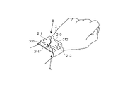
- FIG. 1 is a diagram showing a state in which the wristwatch 1 according to the embodiment is attached to the left arm of the user.
- the arrow A indicates the direction of the line of sight when the user looks at the wristwatch 1 worn on the wrist of the left arm. That is, when the user looks at the wristwatch 1 worn on the wrist of the left arm, the user wears the wristwatch 1 with the elbow of the arm slightly bent toward the user's body (belly or chest side). It is common to see, and it indicates the direction of the line of sight at this time.
- the direction of the arrow A is drawn on the horizontal plane, but the actual direction of the line of sight is generally diagonally downward from the user's eyes.
- FIG. 2 is an enlarged view of a wristwatch 1 mounted on a user's arm as shown in FIG.
- FIG. 2A is an enlarged view of a wristwatch 1 worn on the user's arm when viewed along the direction of arrow A in FIG. 1
- FIG. 2B is a view of the wristwatch 1 worn on the user's arm. It is an enlarged view when the wristwatch 1 is viewed along the arrow B direction of FIG. 1 (the direction substantially opposite to the arrow A).
- the wristwatch 1 shows a state in which the time is displayed in the analog clock display mode in which the hour and minute hands indicate the time.
- FIG. 2 is also a diagram shown for explaining the first display mode of the wristwatch 1 according to the embodiment. The first display mode will be described later.
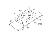
- FIG. 3 is a diagram for explaining the wristwatch main body 100 of the wristwatch 1 according to the embodiment and the display unit 200 formed on five surfaces excluding the lower surface of the wristwatch main body 100.
- FIG. 3A is a perspective view of the wristwatch main body 100
- FIG. 3B is a plan view showing the display unit 200 of the wristwatch 1 developed on five display units 210 to 214.
- the configuration of the wristwatch 1 according to the embodiment will be described with reference to FIGS. 1, 2 and 3.
- the wristwatch 1 according to the embodiment has a rectangular parallelepiped wristwatch body 100 and five of the six surfaces constituting the surface of the wristwatch body 100 (upper surface and four side surfaces) excluding the lower surface facing the user's arm side during use.
- the five display units 210 to 214 formed over the entire area, the belt 300 for attaching the wristwatch 1 to the user's arm, and the display control unit 450 (display) that controls the display of each of the five display units 210 to 214.
- the control unit 450 is described later with reference to FIG. 4).
- "formed over the entire area" is sufficient as long as it appears to be formed over the entire area from the user's point of view, and may not be formed over the entire area in a strict sense.
- the wristwatch main body 100 has a rectangular parallelepiped having a predetermined thickness t, and has an upper surface 110 and four side surfaces (first side surface 111, second side surface 112, opposite to the lower surface).
- five display units 210 to 214 are formed on the five surfaces of the third side surface 113 and the fourth side surface 114).
- the display unit formed on the upper surface 110 of the wristwatch body 100 is referred to as the upper surface display unit 210
- the display unit formed on the first side surface 111 of the wristwatch body 100 is the first side surface display unit.
- the display unit formed on the second side surface 112 of the watch body 100 is the second side surface display unit 212
- the display unit formed on the third side surface 113 of the wristwatch body 100 is the third side surface display unit 213.
- the display unit formed on the fourth side surface 114 of the main body 100 is referred to as the fourth side surface display unit 214.
- the five display units 210 to 214 are composed of five organic EL (Electro Luminescence) display sheets. That is, the upper surface display unit 210 is made of an organic EL display sheet for the upper surface, the first side surface display unit 211 is made of an organic EL display sheet for the first side surface, and the second side surface display unit 212 is made of an organic EL display sheet for the second side surface.
- the third side surface display unit 213 is made of an organic EL display sheet for the third side surface, and the fourth side surface display unit 214 is made of an organic EL display sheet for the fourth side surface.
- each organic EL display sheet is referred to as an organic EL display sheet 210 for the upper surface and an organic EL display sheet for the first side surface.
- the same reference numerals as those of the five display units 210 to 214 are used, such as 211, the organic EL display sheet 212 for the second side surface, the organic EL display sheet 213 for the third side surface, and the organic EL display sheet 214 for the fourth side surface. ..
- the top surface organic EL display sheet 210, the first side surface organic EL display sheet 211, the second side surface organic EL display sheet 212, the third side surface organic EL display sheet 213, and the fourth side surface organic EL display sheet 214 When they are collectively described, they may be expressed as "each organic EL display sheet 210 to 214". Further, when the organic EL display sheet 211 for the first side surface, the organic EL display sheet 212 for the second side surface, the organic EL display sheet 213 for the third side surface, and the organic EL display sheet 214 for the fourth side surface are collectively described, the organic EL display sheet 211 for the first side surface and the organic EL display sheet 214 for the fourth side surface will be described together. It may be expressed as "each side organic EL display sheet 211 to 214".
- Each of these organic EL display sheets 210 to 214 is attached to the upper surface 110 and four side surfaces (first side surface 111, second side surface 112, third side surface 113, and fourth side surface 114) of the wristwatch body 100 one by one.
- the wristwatch 1 as shown in FIGS. 1 and 2 is configured.
- the state in which the analog time is displayed is shown, but when nothing is displayed, the entire display unit 200 is blank.
- the term "no pattern" here means that not only the analog clock display but also the digital clock display and various displays are not performed.
- each organic EL display sheet 210 to 214 is attached to the wristwatch body 100 one by one to form the display unit 200. By doing so, the wristwatch 1 is formed.
- the corners can be at right angles, and the flatness of the organic EL display sheets 210 to 214 can be set. Because it can be raised, it looks neat.
- each organic EL display sheet 210 to 214 is used on the five sides of the wristwatch body 100, that is, the upper surface 110 and the four side surfaces (first side surface 111, second side surface 112, third side surface 113 and fourth side surface 114).
- the first electrode group 120 for supplying electric power and electric signals is exposed and provided.
- a second electrode group 220 for receiving electric power and an electric signal from the first electrode group 120 is provided at a position corresponding to the first electrode group 120. ing.
- the electrodes corresponding to the first electrode group 120 of the wristwatch body 100 and the second electrode group 220 of each of the organic EL display sheets 210 to 214 are electrically connected to each other.
- a drive circuit for supplying an electric signal for controlling the lighting state of each pixel of each organic EL display sheet is provided on the back surface of each organic EL display sheet 210 to 214. In FIG. 3, the drive circuit is not shown.
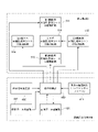
- FIG. 4 is a diagram showing a configuration of a control system for operating the wristwatch 1 according to the embodiment as a functional block diagram.
- the functional block diagram shown in FIG. 4 shows mainly the functional blocks necessary for displaying among the various functions of the wristwatch 1 according to the embodiment.
- a display image selection unit as a user interface that allows the user to select what kind of display is to be displayed on the five display units 210 to 214 (each organic EL display sheet 210 to 214).
- Each organic so that the 410, the image data storage unit 420 that stores the image to be displayed on each organic EL display sheet 210 to 214, and the image to be displayed on each organic EL display sheet 210 to 214 become interlocking or related images.
- the synchronization signal generation unit 430 that generates a synchronization signal for synchronizing between the EL display sheets 210 to 214, the time data generation unit 440 that generates the current time data, and each of the organic EL display sheets 210 to 214.
- the image to be displayed on each of the organic EL display sheets 210 to 214 may be an image stored in the image data storage unit 420, an image generated by an image data generation unit (not shown), or an image generated from the outside. It may be an image received via communication. For example, it may be an image from the user's smartphone or an image from a contracted video distribution company.
- the drive circuit 510 of the organic EL display sheet 210 for the upper surface the drive circuit 511 of the organic EL display sheet 211 for the first side surface, the drive circuit 512 of the organic EL display sheet 212 for the second side surface, It has a drive circuit 513 of the organic EL display sheet 213 for the third side surface and a drive circuit 514 of the organic EL display sheet 214 for the fourth side surface.
- a power supply unit for supplying electric power to each functional block shown in FIG. 4 is also provided on the wristwatch main body 100 side, and the electric power from the power supply unit and the electric power from the power supply unit are provided.
- Various signals from the display control unit 450 are provided on the first electrode group 120 (see FIG. 3A) provided on the wristwatch main body 100 side and on each organic EL display sheet 210 to 214 side, respectively. It is supplied via the second electrode group 220 (see FIG. 3C).
- the display control unit 450 reads out the image stored in the image data storage unit 420 based on the content selected by the user from the display image selection unit 410, and displays the read image on the organic EL display sheets 210 to 214. Control to make it. At this time, the display of each of the organic EL display sheets 210 to 214 is controlled so that the images to be displayed on each of the organic EL display sheets 210 to 214 are interlocked or related.
- the display control unit 450 controls to display the image read from the image data storage unit 420 on the organic EL display sheets 210 to 214, but at the time of starting the wristwatch 1 according to the first embodiment, the display control unit 450 controls. , Controls to display the display image selection screen that functions as the display image selection unit 410. By displaying the display image selection screen on the wristwatch 1, the user can select the content to be displayed from the displayed display image selection screen. Then, the display control unit 450 controls the display based on the display mode selected by the user. The display image may be selected from the selection screen of the user's smartphone linked with the wristwatch.
- the five display units 210 to 214 of the wristwatch 1 according to the first embodiment are in the analog clock display mode, and the display control unit 450 is set to the analog clock display mode.
- the current time data is read from the time data generation unit 440, and as shown in FIG. 2, the organic EL display sheets 210 to 214 display the current time by the hour and minute hands on the organic EL display sheets 210 to 214.
- Each drive circuit 510 to 514 is controlled.
- the display image may be selected from the selection screen of the user's smartphone linked with the wristwatch. A specific method of displaying the time in the analog time display mode will be described later.
- each of the organic EL display sheets 210 to 214 is attached to each of the five surfaces excluding the lower surface among the six surfaces constituting the surface of the wristwatch main body 100. That is, the upper surface organic EL display sheet 210 is attached to the upper surface 110 of the wristwatch body 100, and the first side surface organic EL display sheet 211 is attached to the first side surface 111 of the wristwatch body 100 to display the organic EL for the second side surface.
- the sheet 212 is attached to the second side surface 112 of the wristwatch body 100, the organic EL display sheet 213 for the third side surface is attached to the third side surface 113 of the wristwatch body 100, and the organic EL display sheet 214 for the fourth side surface is a wristwatch.
- the organic EL display sheets 210 to 214 are attached to the corresponding surfaces of the wristwatch body 100 in this way, the organic EL display sheets are placed between the adjacent organic EL display sheets at the corners of the wristwatch body 100. There may be a gap corresponding to the thickness of.
- FIG. 5 is a diagram for explaining how to deal with the gap generated between the adjacent organic EL display sheets.
- FIG. 5 is a diagram showing, for example, a gap generated between the top surface organic EL display sheet 210 and the third side surface organic EL display sheet 213.
- Black member 280 is embedded.
- the black member for example, a member in which silicone rubber or the like is black can be used.
- the space between the top surface organic EL display sheet 210 and the third side surface organic EL display sheet 213 is shown in FIG. 5, the space between the five display units 210 to 214, that is, the first side surface is shown.
- the organic EL display sheet 211 for the second side surface and the organic EL display sheet 212 for the second side surface Between the organic EL display sheet 211 for the second side surface and the organic EL display sheet 212 for the second side surface, between the organic EL display sheet 212 for the second side surface and the organic EL display sheet 213 for the third side surface, and the organic EL display for the third side surface.
- Between the sheet 213 and the organic EL display sheet 214 for the fourth side surface between the organic EL display sheet 214 for the fourth side surface and the organic EL display sheet 211 for the first side surface, and the organic EL display sheet 210 for the upper surface, respectively.
- the gap between the side organic EL display sheets 211 to 214 is also filled with the black member 280.
- the black member 280 is embedded in the corner of the wristwatch body 100, that is, between the adjacent organic EL display sheets. Then, on the surface of each of the organic EL display sheets 210 to 214 in a state where the black member 280 is embedded between the adjacent organic EL display sheets, the protective member 290 so as to cover the entire of the organic EL display sheets 210 to 214. (See FIG. 6) is coated and cured.
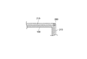
- FIG. 6 is shown for explaining a state in which the protective member 290 is applied and cured so as to cover the entire wristwatch 1.
- FIG. 6 is a cross-sectional view taken along the line aa of FIG. 2A, and components such as the display control unit 450 existing inside the wristwatch body 100 (see the functional block diagram of FIG. 4) are shown. Is omitted.
- a transparent protective member 290 is applied and applied so as to cover the entire five display units of the wristwatch 1, that is, the organic EL display sheet 210 for the upper surface and the organic EL display sheets 211 to 214 for each first side surface. It has been cured.
- the protective member 290 a silicone resin or the like having waterproofness, corrosion resistance and heat resistance can be preferably used.
- the transparent protective member 290 is applied and cured so as to cover the entire five display portions of the wristwatch 1, that is, the organic EL display sheet 210 for the upper surface and the organic EL display sheets 211 to 214 for each first side surface.
- the wristwatch has waterproofness, corrosion resistance, and heat resistance, and is less likely to be damaged, so that a highly reliable wristwatch can be obtained.
- the wristwatch 1 according to the embodiment can be worn on either the left or right arm of the user, but here, as shown in FIG. 1, the wristwatch 1 according to the embodiment is worn on the wrist of the left arm of the user. This case will be explained.
- the first display mode will be described. It is assumed that the user selects the analog clock display from the display image selection unit 410. As a result, the five display units 210 to 214 display the time in the analog clock display mode in which the time is displayed by a plurality of hands, and the five display units 210 to 214 of the wristwatch 1 display the current time.
- the “plurality of hands” can be exemplified by an hour hand, a minute hand, and a second hand, but in the first display mode, a case where the time is displayed by the hour hand and the minute hand will be described.
- the hour hand 230 points between the numerical values "1" and "2" indicating the time on the upper surface display unit 210, and the minute hand 240 extends from the upper surface display unit 210 to the fourth side surface display unit 214. are doing. Specifically, the hour hand is only displayed on the upper surface display unit 210, but the minute hand 240 passes between "8" and "9” on the upper surface display unit 210, and the upper surface display unit 210 and the fourth side surface are displayed. It is bent at the corner portion P1 formed by the display portion 214 and extends to the fourth side surface display portion 214.
- the hands extended and displayed from the upper surface display unit 210 to the fourth side surface display unit 214 may be either the hour hand 230 or the minute hand 240, but the longer hand is the fourth from the upper surface display unit 210. It is preferable to extend the display over the side display unit 214. When comparing the length of the hour hand to the length of the minute hand, the minute hand is generally longer than the hour hand. Therefore, here, the hand extended and displayed from the upper surface display unit 210 to the fourth side surface display unit 214 is a minute hand.
- each side display unit 211 to 214 corresponds to the numbers "1" to "12" displayed on the top surface display unit 210.
- circle mark M it is preferable to display some kind of mark (for example, circle mark M) at the position (see FIG. 2).
- circle mark M By displaying such a circle M, it becomes easy to read the time in minutes in the time of the actual material from the position pointed to by the tip portion Pe of the minute hand 240.
- the display control for displaying the hour hand 230 and the minute hand 240 in this way is performed by the display control unit 450. That is, in the wristwatch 1 according to the embodiment, the display control unit 450 extends the minute hand 240 from the upper surface display unit 210 to one side surface of each side surface display unit 211 to 214, and is displayed on the upper surface display unit 210.
- the five display units 210 to 214 that is, the organic EL display sheets 210 to 214 so that the minute hand 241 and the minute hand 242 displayed on at least one of the four side surfaces rotate in conjunction with each other. Control each display.
- the specific display control of the minute hand 240 in this case is referred to as a minute hand 241 displayed on the upper surface display unit 210, that is, a minute hand 241 displayed between the rotation shaft portion Po and the corner portion P1 (top surface display minute hand 241).
- the minute hand displayed on the fourth side surface display unit 214 that is, the minute hand 242 displayed between the corner portion P1 and the tip portion Pe of the minute hand 240 (referred to as the side surface display minute hand 242) rotate in conjunction with each other.
- the drive circuit 510 of the top surface organic EL display sheet 210 and the drive circuit 514 of the fourth side surface organic EL display sheet 214 are controlled based on the synchronization signal from the synchronization signal generation unit 430.
- the display control for displaying the hour hand 230 drives the drive circuit 510 of the upper surface organic EL display sheet 210 so that the hour hand 230 rotates about the rotation shaft portion Po on the upper surface display unit 210.
- the minute hand 240 is displayed on the fourth side surface display unit 214
- the upper surface display minute hand 241 is displayed on the upper surface organic EL display sheet 210 as a so-called clock. It is displayed so as to rotate in the clockwise direction, and the side surface display minute hand 242 is displayed so as to rotate in the so-called clockwise direction on each side surface display unit 211 to 214 in conjunction with the top surface display minute hand 241.
- the minute hand 240 may be displayed according to the position of the minute hand 240. It is necessary to make the length (the length from the rotation shaft portion Po to the corner portion P1) different. For example, it is necessary to control the display so that the length of the upper surface display minute hand 241 differs between the case where the minute hand 240 is located at "9" of the fourth side surface display unit 214 and the case where the minute hand 240 is located at "11". ..
- the length of the upper surface display minute hand 241 is set in advance according to the position of the minute hand 240, and in the display control unit 450, the upper surface display minute hand 241 set according to the position of the minute hand 240 is set.
- the top display minute hand 241 is displayed based on the length of.
- the wristwatch 1 in the first display mode, not only the hour hand 230 and the minute hand 240 are displayed on the upper surface display unit 210, but also the minute hand 240 is displayed from the upper surface display unit 210 on one side surface of each side surface display unit 211 to 214. It is displayed in a stretched state over the display unit.
- the wristwatch 1 according to the embodiment can be displayed as in the first display mode, so that the wristwatch 1 has a new value that has never existed before.
- the hour hand 230 is displayed on the upper surface display unit 210 in the same manner as in the first display mode shown in FIG. 2, and is displayed so as to extend toward one side surface of each side surface display unit 211 to 214 of the minute hand 240.
- the numbers "1" to "12" may be displayed on both the top surface display unit 210 and each side surface display unit.
- the wristwatch 1 By performing the display according to the modification 1 of the first display mode, the wristwatch 1 according to the embodiment becomes a wristwatch having a new value that has never existed before.
- FIG. 8 is a diagram for explaining a second display mode of the wristwatch 1 according to the embodiment.
- the second display mode of the wristwatch 1 according to the embodiment is also the case where the five display units 210 to 214 are set to the analog clock display mode, as in the first display mode described above.
- the numerical values "1" to "12" representing the time are the organic EL display sheets for each side surface, as in the modification 1 (see FIG. 7) of the first display mode described above. It shall be displayed in 211 to 214.
- the display control unit 450 displays the time in the analog clock display mode so that the inside of the wristwatch main body 100 can be seen through from the user's point of view. Is displayed positively on the third side display unit 213 and the fourth side surface display unit 214 of the wristwatch body 100, and is displayed reversely on the left and right sides on the first side surface display unit 211 and the second side surface display unit 212. The display of each of the display units 210 to 214 is controlled.
- the display control of each of the organic EL display sheets 210 to 214 so that the inside of the wristwatch body 100 can be seen through is to control the display as if the wristwatch body 100 is a transparent container.
- the user can visually recognize the inner side surface of the wristwatch body 100 (the inner side surface 111a of the first side surface 111 and the inner side surface 112a of the second side surface 112), and the inner bottom surface of the wristwatch body 100.
- the display is controlled so that the 115a can be visually recognized by the user.
- the "transparent container” in this case may be a colorless and transparent container or a colored transparent container having light transmission.
- the inside of the wristwatch body 100 can be seen through as if viewed from the user. That is, the wristwatch body 100 looks as if it is a transparent container. In particular, "11", “12", “1” and “1", “3”, “4" displayed on the first side surface display unit 211 and the second side surface display unit 212, which are originally invisible to the user. Because each number is displayed upside down from the user's point of view, the user feels as if the wristwatch body 100 is a transparent container and the inside of the wristwatch body 100 can be seen through. Will be.
- the hour hand 230 and the minute hand 240 are displayed on the upper surface display unit 210 which looks transparent to the user.
- the minute hand 240 is shown to be displayed only on the upper surface display unit 210, but as in the first display mode, the minute hand 240 extends to one side surface display unit of each side surface display unit 211 to 214. It may be displayed as.
- the inside of the wristwatch body 100 can be seen through from the user's point of view, and the display of the numerical value indicating the time in the analog clock display mode is displayed on the third side surface display unit 213 and the third display unit.
- the wristwatch according to the embodiment is displayed positively on the left and right sides of the side display unit 214, and reversely displayed on the left and right sides in the area corresponding to the first side surface display unit 211 and the second side surface display unit 212 on the top surface display unit 210.
- 1 is a wristwatch with new value that has never existed before.
- the first side surface display unit 211 and the second side surface display unit 212 are invisible to the user, it may be possible not to display a numerical value or other display indicating the time in the analog clock display mode, but other than the user.
- the display of the numerical value indicating the time may be displayed correctly on the left and right so that a person does not feel uncomfortable when looking at the wristwatch.
- FIG. 9 is a diagram for explaining a third display mode of the wristwatch 1 according to the embodiment.
- the third display mode of the wristwatch 1 according to the embodiment is also the case where the five display units 210 to 214 are set to the analog clock display mode, as in the first display mode and the second display mode described above.
- the display control unit 450 displays and controls the display so that the inside of the wristwatch body 100 can be seen through from the user's point of view. , The display is controlled as if the wristwatch body 100 is a transparent container. However, in the third display mode, the display control unit 450 controls the display so that the hour hand 230 and the minute hand 240 rotate while being located inside the wristwatch main body 100.
- the display control for allowing the inside of the wristwatch body 100 to be seen through as if viewed from the user at the time of use is the same as the second display mode, that is, the side surface inside the wristwatch body 100 (the inside of the first side surface 111).
- This can be realized by controlling the display so that the user can see the side surface 111a and the inner side surface 112a of the second side surface 112, respectively, and the inner bottom surface 115a of the wristwatch body 100 can be seen by the user.
- "11", “12", “1” and "1” displayed on the first side surface display unit 211 and the second side surface display unit 212 which are not originally visible to the user. , "3", and "4" are displayed and controlled so that the individual numbers are displayed upside down when viewed from the user.
- the hour hand 230 and the minute hand 240 are displayed so as to rotate while being located inside the wristwatch body 100.
- displaying the hour hand 230 and the minute hand 240 so as to rotate while they are located inside the wristwatch body 100 means that the rotation shaft portion Po of the hour hand 230 and the minute hand 240 is in the thickness t direction of the wristwatch body 100.
- the hour hand 230 and the minute hand 240 are displayed so as to be rotated while the hour hand 230 and the minute hand 240 are displayed so as to fit inside the wristwatch main body 100.
- the inner side surface 111a and the second side surface 112 of the first side surface 111 inside the wristwatch main body 100 are viewed from the user, as in the second display mode described above.
- the inner side surface 112a of the wristwatch can be visually recognized, and the inner bottom surface 115a of the wristwatch body 100 can be visually recognized.
- the third display mode it appears to the user that the hour hand 230 and the minute hand 240 rotate in a state of being located inside the wristwatch main body 100.
- the inside of the wristwatch body can be seen through from the user's point of view, and the hour and minute hands appear to rotate while being located inside the wristwatch body.
- the wristwatch 1 according to the embodiment is a wristwatch having a new value that has never existed before.
- FIG. 10 is a diagram for explaining a fourth display mode in the wristwatch 1 according to the embodiment.
- the digital clock display mode here is a display mode in which the time is displayed numerically instead of being represented by the hour and minute hands.
- the fourth display mode not only the time but also the date, the day of the week, and other information shall be displayed.
- the user can digitally display the five display units 210 to 214 by, for example, selecting "digital clock display" from the display image selection screen that functions as the display image selection unit 410. It can be set to the clock display mode.
- the current time such as 10:25:34 is set to "10:
- today's date such as October 1, 2020 is displayed as "20.10.01”
- today's day of the week is displayed as "Thursday”.
- today's weather forecast is displayed on each side surface display unit 211 to 214 (fourth side surface display unit 214 in the example of FIG. 10) by a weather mark or the like. It should be noted that these various types of information can also be displayed so as to flow on each display unit. As an example, it is also possible to display the day of the week in a flowing manner so that various information is displayed one after another after the day of the week.
- various information including the digital clock display can be displayed as images by using the five display units 211 to 214, and some information (images) or all of them can be displayed. Since the information (image) can be displayed in a flowing manner, the wristwatch 1 according to the embodiment can be a wristwatch having a new value that has never existed before.
- FIG. 11 is a diagram shown for explaining the fifth display mode of the wristwatch 1 according to the embodiment.
- the fifth display mode is such that the liquid is contained in the transparent container as if the user sees it, and the liquid is repeatedly increased and decreased in the transparent container.
- the user selects, for example, "other display modes” from the display image selection screen that functions as the display image selection unit 410, and further, a plurality of "other display modes". For example, select "Pattern 1" from the options of.
- the display is performed by the fifth display mode as shown in FIG.
- the wristwatch body 100 looks like a transparent container to the user, and at the same time, it looks as if a liquid (shown in gray) is contained in the transparent container. .. Then, the liquid contained in the transparent container repeatedly increases and decreases while shaking in the transparent container. When the liquid performs such an operation in the transparent container, the user feels fun and mysterious just by looking at the movement of the liquid, and the user does not get tired of it.
- the display may be controlled so that the color of the liquid gradually changes.
- the wristwatch 1 As described above, in the fifth display mode, the wristwatch 1 according to the embodiment is displayed because the liquid is contained in the transparent container from the user's point of view and the liquid is repeatedly increased and decreased in the transparent container. Although it is originally a wristwatch, it can display other than displaying the time, so it will be a wristwatch with new value that has never existed before.
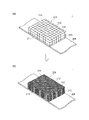
- FIG. 12 is a diagram for explaining a sixth display mode in the wristwatch 1 according to the embodiment. Similar to the fifth display mode, the sixth display mode is also a display mode when various display modes other than the time display mode are set. In this case, the user selects, for example, "other display modes" from the display image selection screen that functions as the display image selection unit 410, and further, for example, “other display modes” from a plurality of options. It is assumed that "Pattern 2" is selected. As a result, the display as shown in FIG. 12 is started.
- the five display units 210 to 214 display a grid pattern. Then, as shown in FIGS. 12 (a) and 12 (b), a display is performed so as to change the size of the squares formed by the lattice. At this time, the change in the size of the squares may be continuously and gradually changed, or may be changed stepwise to large, medium, and small. Further, the entire lattice pattern may be displayed so as to move from the right to the left in the figure, for example.
- a predetermined pattern can be displayed on the entire five display surfaces, and the size of the pattern can be changed and displayed while flowing. Therefore, the wristwatch 1 according to the embodiment. Although it is originally a wristwatch, it can display other than displaying the time, so it will be a wristwatch with new value that has never existed before.
- the wristwatch 1 according to the embodiment is a wristwatch having a new value that has never existed before.
- FIG. 13 is a diagram shown for explaining the seventh display mode of the wristwatch 1 according to the embodiment. Similar to the fifth display mode and the sixth display mode, the seventh display mode is also a display mode when various display modes other than the time display mode are set. In this case, the user selects, for example, "other display modes” from the display image selection screen that functions as the display image selection unit 410, and further, for example, “other display modes” from a plurality of options. It is assumed that "Pattern 3" is selected. As a result, it is assumed that the display as shown in FIG. 13 is started.
- the seventh display mode is such that a large number of polka-dot-like patterns are displayed as if they flow through the five display units 210 to 214 when viewed from the user.
- a large number of polka dots are generated in the third side surface display unit 213 so that the generated individual polka dots gradually grow larger, and the upper surface display unit 210, the fourth side surface display unit 214, and the second side surface are formed.
- the display is controlled so as to flow through the display unit 212 and the first side surface display unit 211. The user will find it fun and mysterious just by looking at the movement of the polka dots, and will never get tired of it.
- the display control may be performed such that the color of the polka dots is changed for each individual polka dot, or the color is changed as the polka dots grow.
- the wristwatch 1 in the seventh display mode, a pattern like a polka dot is displayed on the entire five display units, and the pattern is displayed so as to flow while changing the size or color of the pattern. Therefore, the wristwatch 1 according to the embodiment is originally a wristwatch, but can display other than displaying the time, so that it is a wristwatch having a new value that has never existed before.
- FIG. 14 is a diagram shown for explaining the eighth display mode of the wristwatch 1 according to the embodiment.
- the eighth display mode is also a display mode when various display modes other than the time display mode are set, as in the fifth display mode to the seventh display mode.
- the user selects, for example, "other display modes” from the display image selection screen that functions as the display image selection unit 410, and further, for example, “other display modes” from a plurality of options. It is assumed that "Pattern 4" is selected. As a result, it is assumed that the display as shown in FIG. 13 is started.
- the eighth display mode controls the display so that the rectangular parallelepiped wristwatch 1 is divided into a plurality of blocks as if viewed from the user.
- the rectangular parallelepiped wristwatch 1 is displayed as if it were divided into four blocks as shown in FIG. 14, and then each of the four blocks is displayed so as to be further subdivided.
- Display control is performed such as returning to (the state before division). In this case, display control may be performed such that the color of each block is changed or the color is changed for each predetermined area.
- the rectangular parallelepiped wristwatch 1 can be displayed as if it is divided into a plurality of blocks from the user's point of view. Therefore, the wristwatch 1 according to the embodiment is originally Although it is a wristwatch, it can display other than displaying the time, so it will be a wristwatch with new value that has never existed before.
- FIG. 15 is a diagram for explaining a ninth display aspect of the wristwatch 1 according to the embodiment.
- the ninth display mode is also a display mode when various display modes other than the time display mode are set, as in the fifth display mode to the eighth display mode.
- the fifth display mode to the eighth display mode are display modes for displaying a pattern
- the ninth display mode is a display mode for displaying a composite image on the wristwatch 1 according to the embodiment.
- the composite image is to display various images such as a time image, a monthly calendar image, and a photograph so as to be interlocked with or related to the five display units 210 to 214.
- the user selects, for example, "composite" from the display image selection screen.
- the display as shown in FIG. 15 is assumed. In this case, since various images can be displayed not only on the upper surface display unit 210 of the wristwatch 1 but also on the side surface display units 211 to 214, various complex images can be displayed.
- the wristwatch 1 since various complex images can be displayed by using all of the five display units, the wristwatch 1 according to the embodiment is originally a wristwatch, but has a time. Since it is possible to display other than the display of, it will be a wristwatch with new value that has never existed before.
- the display mode of the wristwatch 1 As described above, as the display mode of the wristwatch 1 according to the embodiment, the first display mode to the ninth display mode have been described, but these are examples, and various displays can be performed. For example, it is possible to display a rectangular parallelepiped wristwatch 1 as if it were a water tank so that a fish can swim, or to display a modeled flower from a bud state to flowering at a high speed.
- the five display units 210 to 214 (top surface display unit 210 and each side surface display unit 211 to 214) of the rectangular parallelepiped wristwatch main body 100 show images in various embodiments. It becomes possible to display. Further, when displaying an image on the five display units 210 to 214, the display of each of the five display units is controlled so that the images displayed on each of the five display units 210 to 214 are interlocked or related. Therefore, the wristwatch 1 will be used in various ways, and it will be possible to provide a wristwatch with new value that has never existed before.
- the second hand is not mentioned, but the hour hand and the minute hand are not mentioned. In addition, the second hand can be displayed.
- the present invention has the display control unit 450 in which at least the longest hand among the plurality of hands displays four sides from the top display unit 210.
- a part of the needles extending to one side display unit (each side display unit 211 to 214) and extending to one side surface display unit, which is displayed on the upper surface display unit 210, and one side surface display unit.
- the display of each of the five display units is controlled so that the portion displayed on the screen rotates in conjunction with the portion displayed on the screen.
- the minute hand 230 is the upper surface display unit. It is displayed so as to extend from 210 to one of the side display units 211 to 214.
- the second hand when the plurality of hands are an hour hand, a minute hand and a second hand, and the length of each hand is hour hand ⁇ minute hand ⁇ second hand (here, " ⁇ " represents an inequality sign), the second hand.
- Only the top surface display unit 210 is displayed so as to extend from the side surface display unit 210 to one of the side surface display units 211 to 214.
- the "at least the longest hand” is used among the plurality of hands, not only the longest second hand but also the second longest minute hand is from the top display unit 210 to the side surface display units 211 to 214. It may be displayed so as to extend over one side display unit.
- the plurality of hands are an hour hand, a minute hand and a second hand, and the length of each hand is hour hand ⁇ second hand ⁇ minute hand
- only the minute hand is displayed from the upper surface display unit 210 to each side surface display unit 211 to. It is displayed so as to extend to one of the side display portions of 214.
- the "at least the longest hand" is used among the plurality of hands, not only the longest minute hand but also the second longest second hand is from the top display unit 210 to one of the side surface display units 211 to 214. It may be indicated that it is stretched over.
- the minute hand and the second hand are moved from the upper surface display unit 210 to each side surface display unit 211. It is displayed so as to extend to one of the side display portions of ⁇ 214. By doing so, the "at least the longest needle" is displayed so as to extend from the top surface display unit 210 to one of the side surface display units 211 to 214.
- the color of the display content is not mentioned, but it is of course possible to perform so-called color display.
- color display for example, in the case of analog clock display, it is possible to display the hour hand and the minute hand in different colors, or to display so that the colors change at the hour such as 1 o'clock and 2 o'clock.
- the five display units 210 to 214 have five organic EL display sheets (top surface organic EL display sheet 210, first side surface organic EL display sheet 211, second side surface organic EL display).
- the case of the sheet 212, the organic EL display sheet 213 for the third side surface, and the organic EL display sheet 214 for the fourth side surface) is illustrated, but the five display units 210 to 214 are composed of one organic EL display sheet. There may be.
- FIG. 16 is a diagram for explaining the case where the five display units 210 to 214 are composed of one organic EL display sheet.
- the organic EL display sheet has a shape as shown in FIG.
- one organic EL display sheet includes the organic EL display sheet 210 for the upper surface existing in the center, the organic EL display sheet 211 for the first side surface, the organic EL display sheet 212 for the second side surface, and the organic EL for the third side surface.
- the display sheet 213 and the organic EL display sheet 214 for the fourth side surface have a shape extending in all directions.
- One organic EL display sheet having such a shape is bent along the broken line shown in FIG. 16 so as to follow the outer shape of the wristwatch main body 100 (see FIG. 3A) and attached to the wristwatch main body 100. ..
- the configuration can be the same as that of the wristwatch 1 according to the above embodiment.
- the five display units 210 to 214 are composed of one organic EL display sheet, no gap is formed in the bent portion (the portion shown by the broken line in FIG. 16). Therefore, in the bent portion, FIG. 5 It is no longer necessary to fill with the black member described in the above.
- a gap corresponding to the thickness of the organic EL display sheet may be formed in the corner portion of each side surface display portion, it is preferable to fill the gap with a black member. That is, in one organic EL display sheet shown in FIG.
- the five display units 210 to 214 are composed of one organic EL display sheet, it becomes easy to link or display the images to be displayed on the upper surface and each side surface, and the organic EL can be easily displayed.
- the drive of the display sheet can be simplified. Therefore, since the power supply and the electric signal supply from the wristwatch body 100 side to the organic EL display sheet side may be performed on one organic EL display sheet, the wristwatch body 100 side and one sheet may be supplied.
- An electrode group may be provided at one corresponding location on the side of the organic EL display sheet.
- FIG. 17 is a diagram for explaining a case where the user looks at the wristwatch 1 with his / her arm bent more strongly in the second display mode of the wristwatch 1 according to the embodiment.
- the display control unit 450 displays the time in the analog clock display mode, and the third side display unit 213 and the fourth side display unit 214 display the time on the left and right.
- the display control of the third side surface display unit 213 and the fourth side surface display unit 214 is performed so that the display is correctly displayed, and the left and right sides are displayed upside down on the first side surface display unit 211 and the second side surface display unit 212 as if viewed from the user.
- the display of the upper surface display unit 210 was controlled, because the third side surface display unit 213 and the fourth side surface display unit 214 are located at positions that the user can see.
- the display control unit 450 controls the display of the second side surface display unit 212 and the third side surface display unit 213 so that the left and right sides are correctly displayed on the second side surface display unit 212 and the third side surface display unit 213.
- FIG. 18 is a diagram for explaining another display mode (10th display mode) of the wristwatch 1 according to the embodiment.
- the tenth display mode is similar to the fifth display mode (see FIG. 11), but as shown in FIG. 18, the liquid 250 is contained in the wristwatch 1 as if it were contained in the wristwatch 1 from the user's point of view. Moreover, the liquid 250 appears to be shaking, and the current time 252 is displayed on the upper surface display unit 210.
- the display control unit 450 controls the display of each of the five display units 210 to 214 so that the display mode as described above is possible.
- FIG. 19 is a diagram for explaining another display mode (11th display mode) of the wristwatch 1 according to the embodiment.
- the eleventh display mode is a display mode in which a state in which the ribbon 254 is wound around the wristwatch 1 is displayed. In the eleventh display mode, it may be displayed that the ribbon 254 is wound or the wound ribbon 254 is unwound with the passage of time.
- the display control unit 450 controls the display of each of the five display units 210 to 214 so that the display mode as described above is possible.
- FIG. 20 is a diagram for explaining another display mode (12th display mode) of the wristwatch 1 according to the embodiment.
- the twelfth display mode is a display mode in which the current time 252 is displayed on the upper surface display unit 210 in addition to the display of the eleventh display mode.
- the display control unit 450 controls the display of each of the five display units 210 to 214 so that the display mode as described above is possible.
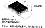
- FIG. 21 is a diagram for explaining another display mode (13th display mode) of the wristwatch 1 according to the embodiment.
- the thirteenth display mode is a display mode in which fine particles 256 permeate from the upper surface to the bottom surface of the wristwatch 1.
- the display mode may be such that the surface color changes periodically and fine particles of another color permeate into the display mode.
- the display control unit 450 controls the display of each of the five display units 210 to 214 so that the display mode as described above is possible.
- FIG. 22 is a diagram for explaining another display mode (14th display mode) of the wristwatch 1 according to the embodiment.
- the 14th display mode is a display mode in which a plurality of images 258 constituting the frame of the video are deposited from the present (top surface) to the past (bottom surface). Then, with the passage of time, the past image of the plurality of images 258 is displayed on the upper surface display unit 210. Further, the end faces 260 of the plurality of accumulated images 258 are displayed on the four side surface display units 211 to 214.
- the display control unit 450 controls the display of each of the five display units 210 to 214 so that the display mode as described above is possible.
- FIG. 23 is a diagram for explaining another display mode (15th display mode) of the wristwatch 1 according to the embodiment.
- the fifteenth display mode as shown in FIG. 23, a state in which small spheres 262 are dispersed and randomly moving in a rectangular parallelepiped is displayed as an initial state, and then, with the passage of time, small spheres 262 are displayed on the upper surface. It is a display mode in which a state in which the current time 252 appears after gathering is displayed.
- the small sphere 262 may, for example, move with the passage of time or with the movement of the hand.
- the display control unit 450 controls the display of each of the five display units 210 to 214 so that the display mode as described above is possible.
- [16th display mode] 24 and 25 are views for explaining another display mode (16th display mode) of the wristwatch 1 according to the embodiment.
- the current time 252 is displayed on the upper surface display unit 210 as an initial state, but when acceleration is applied to the wristwatch due to, for example, the movement of the arm, it is displayed. It is a display mode in which the current time 252 moves and protrudes to the side as a trigger.
- FIG. 25 shows a series of movements in which the current time protrudes to one or more side display units of the side display units 211 to 214 in addition to the top display unit 210.
- the four numbers constituting the current time change the display mode from a to h in FIG.
- the display control unit 450 controls the display of each of the five display units 210 to 214 so that the display mode as described above is possible.
- FIG. 26 is a diagram for explaining another display mode (17th display mode) of the wristwatch 1 according to the embodiment.
- the current time 252 is displayed on the upper surface display unit 210 in the initial state, but when acceleration is applied to the wristwatch due to the movement of the arm, for example, the movement is triggered.
- This is a display mode (an illusionary display mode) in which the pseudo wristwatch frame 264 appears to vibrate inside the wristwatch 1.
- the display control unit 450 controls the display of each of the five display units 210 to 214 so that the display mode as described above is possible.
- FIG. 27 is a diagram for explaining another display mode (18th display mode) of the wristwatch 1 according to the embodiment.
- the eighteenth display mode as shown in FIG. 27, different flows in the flow direction 266 are generated for each display surface (top surface display unit 210 and four side surface display units 211 to 214), and the flow is, for example, It is a display mode that changes as shown in the upper figure and the lower figure of FIG. 27 every second.
- the display control unit 450 controls the display of each of the five display units 210 to 214 so that the display mode as described above is possible.
- FIG. 28 is a diagram for explaining another display mode (19th display mode) of the wristwatch 1 according to the embodiment.
- the 19th display mode is a display mode in which the pattern 268 representing the pressure change on the time axis is displayed on the side display units 211 to 214.
- a pattern 268 representing a pressure change on the time axis a pattern representing a user's heartbeat is displayed on four side display units 211 to 214 and a top surface display unit.
- It may be a display mode as a so-called heart rate monitor, for example, moving on the 210 counterclockwise.
- FIG. 28 is a diagram for explaining another display mode (19th display mode) of the wristwatch 1 according to the embodiment.
- the 19th display mode is a display mode in which the pattern 268 representing the pressure change on the time axis is displayed on the side display units 211 to 214.
- a pattern representing a user's heartbeat is displayed on four side display units 211 to 214 and a top surface display unit.
- It
- the pattern showing the sound pressure of the music being played is, for example, counterclockwise on the four side display portions 211 to 214.
- the display control unit 450 controls the display of each of the five display units 210 to 214 so that the display mode as described above is possible.
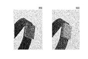
- [20th display mode] 29 and 30 are views for explaining another display mode (20th display mode) of the wristwatch 1 according to the embodiment.
- the twentieth display mode is a display mode in which the display is switched by the swipe operation. For example, as shown in the upper figure of FIG. 29, as an initial state, the first is displayed on the four display units of the top surface display unit 210, the first side surface display unit 211, the second side surface display unit 212, and the third side surface display unit 213. Image G1 is displayed, and the second image G2 is displayed on the remaining fourth side surface display unit 214. Then, as shown in the lower figure of FIG.
- the boundary between the first image G1 and the second image G2 with a finger by swiping an arbitrary portion P of the boundary between the first image G1 and the second image G2 with a finger, the first image G1 and the second image G1 and the second image G1 are swiped.
- the boundary with the image G2 and the boundary between the second image G2 and the third image G3 (not shown) are pulled and moved.
- the boundary between the first image G1 and the second image G2 and the second image G2 This is a display mode in which the boundary with the third image G3 is displayed as if it were attracted to something and stopped.
- the display control unit 450 controls the display of each of the five display units 210 to 214 so that the display mode as described above is possible.
- a touch panel having a touch pad arranged on the surface of each of the five organic EL display sheets is used as the five display units 210 to 214.
- the touch pad may be arranged on the surface of the black member 280.
- the five display units 210 to 214 are composed of five organic EL display sheets (see FIG. 3B) is exemplified, and as a modification of the above embodiment, as a modification.
- the unit 31 is composed of one organic EL display sheet in which the first side surface display unit 211, the top surface display unit 210, and the third side surface display unit 213 are connected, and the second side surface display unit 212 and the fourth side surface display unit.
- the unit 214 is composed of two organic EL display sheets separated into one sheet each. As a result, the five display units 210 to 214 are composed of three organic EL display sheets.
- the example in which the five display units 210 to 214 are composed of three organic EL display sheets is not limited to this, and although not shown, for example, the second side surface display unit 212 and the top surface display unit It is composed of one organic EL display sheet in which 210 and the fourth side surface display unit 214 are connected, and two organic sheets in which the first side surface display unit 212 and the third side surface display unit 214 are separated into one each. It may consist of an EL display sheet. As a result, the five display units 210 to 214 are composed of three organic EL display sheets.
- the five display units 210 to 214 may be composed of two organic EL display sheets.
- it is composed of one organic EL display sheet in which the first side surface display unit 211 to the fourth side surface display unit 214 are connected, and is composed of one organic EL display sheet in which only the top surface display unit 210 is separated.
- the five display units 210 to 214 are composed of two organic EL display sheets.
- the five display units 210 to 214 may be composed of four organic EL display sheets.
- it is composed of one organic EL display sheet in which the first side surface display unit 211 and the top surface display unit 210 are connected, and the second side surface display unit 212, the third side surface display unit 213, and the fourth side surface display unit 214 are 1 respectively. It consists of three organic EL display sheets separated from each other. As a result, the five display units 210 to 214 are composed of four organic EL display sheets.
- the wristwatch has been described as having five display units, but it does not have to have five display units. That is, in the wristwatch of the present invention, of the rectangular parallelepiped wristwatch body 100 and the six surfaces constituting the surface of the wristwatch body 100, "the upper surface opposite to the lower surface facing the user's arm side at the time of use" and "four". It may include at least two display units formed over the entire area of "at least one side surface” and a display control unit that controls the display of each of the at least two display units. That is, in the wristwatch 1 according to the above embodiment, at least two display units are five display units formed over the entire area of each of the five surfaces composed of the upper surface and the four side surfaces. It may have at least two display units instead of the display unit.
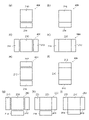
- FIG. 32 is a diagram showing an example of a case where the display unit 20 is composed of at least two display units.
- the display unit 200 of a wristwatch having 2 to 4 display units is developed and shown as at least two display units.
- FIGS. 32 (a) and 32 (b) have two display units
- FIGS. 32 (c) to 32 (f) have three display units
- (G)-FIG. 32 (i) is a case where four display units are provided.
- FIG. 32 in a wristwatch having 2 to 4 display units, there is a surface having no display unit composed of an organic EL display sheet, but a display composed of an organic EL display sheet.
- a protective member may be applied and cured even on a surface having no portion.
- each display unit may be composed of a plurality of organic EL display sheets, and one organic sheet may be used. It may consist of an EL display sheet. That is, FIGS. 32 (a) and 32 (h) are cases where each display unit is composed of two organic EL display sheets, and FIGS. 32 (c) and 32 (e) are displays. Each unit is composed of three organic EL display sheets, and FIG. 32 (g) shows a case where each display unit is composed of four organic EL display sheets. Further, FIGS. 32 (b), 32 (d), 32 (f), and 32 (i) show a case where each display unit is composed of one organic EL display sheet.
- the upper surface display unit 210 may be square in FIGS. 31 and 32, it may be rectangular as shown in FIG. 3 or the like used in the description of the above-described embodiment. On the contrary, in the above-described embodiment, the upper surface display unit 210 is rectangular, but the upper surface display unit 210 may be square.
- the display unit 200 (five display units 210 to 214) is composed of an organic EL display sheet is exemplified, but the display unit 200 (five display units 210 to 214) is composed of a micro LED (Light Emitting Diode) display sheet. May be good.
- a wristwatch-type display device can be used as well as a wristwatch.
- a wristwatch-type display device of the six surfaces constituting the surface of the rectangular parallelepiped wristwatch-type display device body and the wristwatch-type display device body, "the side opposite to the lower surface facing the user's arm side during use". It includes at least two display units formed over the entire area of each of the "top surface” and "at least one side surface of the four side surfaces", and a display control unit that controls the display of each of the at least two display units.
- the display control unit has a function of controlling the display of each of the at least two display units so that the images to be displayed on each of the at least two display units are interlocked or related.
- at least two display units are five display units formed over the entire area of each of the five surfaces composed of the upper surface and the four side surfaces.
- the display control performed by the display control unit 450 may be set so as to perform display control peculiar to the wristwatch-type display device, which is not particularly required for the wristwatch.
- the wristwatch-type display device of the present invention it is possible to display various images in various modes by using the side surface in addition to the upper surface of the rectangular parallelepiped wristwatch-type display device main body. Therefore, according to the wristwatch-type display device of the present invention, it is possible to provide a wristwatch-type display device having a new value that has never existed in the past.
- the wristwatch-type display device of the present invention can also be modified in the same manner as the wristwatch of the present invention.
- 4th side surface display unit (organic EL display sheet for the fourth side surface), 210 to 214 ... 5 display units, 211 to 214 ... 4 Two side display units (each side display unit), 220 ... second electrode group, 230 ... hour hand, 240 ... minute hand, 241 ... top display minute hand unit, 242 ... side display minute hand unit, 250 ... liquid, 252 ... current time, 254 ... ribbon, 256 ... fine particles, 258 ... multiple images, 260 ... end faces, 262 ... small spheres, 264 ... Pseudo-watch frame, 266 ... flow direction, 268 ... pattern, 270 ... icon, 272 ... swipe direction, 280 ... black member, 290 ...
- protective member 300 ... belt, 410 ... display image selection unit, 420 ... image data storage unit, 430 ... synchronization signal generation unit, 440 ... time data generation unit, 450 ... display control unit, 510 ... Drive circuit of organic EL display sheet for top surface 511 ... Drive circuit of organic EL display sheet for first side surface 512 ... Drive circuit of organic EL display sheet for second side surface 513 ... Drive circuit of organic EL display sheet for third side surface, 514 ... Drive circuit of organic EL display sheet for fourth side surface, G1 ... first image, G2 ... second image, P ... Arbitrary part, Po ... Rotating shaft part, P1 ... Corner part, Pe ... Minute hand tip
Abstract
Description
図1は、実施形態に係る腕時計1を使用者の左腕に装着した状態を示す図である。なお、図1において矢印Aは、左腕の手首に装着されている腕時計1を使用者が見る際の視線の方向を示している。すなわち、左腕の手首に装着されている腕時計1を使用者が見る際においては、使用者は腕の肘を当該使用者の身体(腹又は胸側)に少し曲げるようにした状態で腕時計1を見ることが一般的であり、このときの視線の方向を示している。図1においては、矢印Aは水平面上での方向が描かれているが、実際の視線の方向は、使用者の目から斜め下方向に向くこととなるのが一般的である。
第1表示態様について説明する。使用者は、表示画像選択部410からアナログ時計表示を選択したとする。これにより、5つの表示部210~214は複数の針で時刻を表示するアナログ時計表示モードによる表示を行い、腕時計1の5つの表示部210~214には、現在の時刻が表示される。ここで、「複数の針」というのは、時針、分針及び秒針を例示できるが、第1表示態様においては、時針と分針により時刻表示を行う場合について説明する。
上述の第1表示態様では、時刻を表す「1」から「12」の数字は、上面表示部210に表示させる場合を例示したが、図7に示すように、各側面表示部211~214に表示させるようにしてもよい。すなわち、表示制御部450は、「11」、「12」、「1」を第1側面表示部211に表示させ、「2」、「3」、「4」を第2側面表示部212に表示させ、「5」、「6」、「7」を第3側面表示部213に表示させ、「8」、「9」、「10」を第4側面表示部214に表示させるように各有機EL表示シート211~214の駆動回路を制御する。この場合、上面表示部210においては、各側面表示部211~214に表示される「1」から「12」の数字に対応する位置に丸印Mを表示させることが好ましい。
図8は、実施形態に係る腕時計1の第2表示態様について説明するために示す図である。実施形態に係る腕時計1の第2表示態様も前述した第1表示態様と同様に、5つの表示部210~214をアナログ時計表示モードに設定した場合である。なお、第2表示態様においては、前述の第1表示態様の変形例1(図7参照。)と同様に、時刻を表す「1」から「12」の数値は、各側面用有機EL表示シート211~214に表示させるものとする。また、実施形態に係る腕時計1の第2表示態様においては、表示制御部450は、使用者から見てあたかも、腕時計本体100の内部が透けて見えるように、かつ、アナログ時計表示モードにおける時刻表示が、腕時計本体100の第3側面表示部213及び第4側面表示部214においては左右正表示され、第1側面表示部211及び第2側面表示部212においては左右逆表示されるように5つの表示部210~214のそれぞれの表示を制御する。
図9は、実施形態に係る腕時計1の第3表示態様について説明するために示す図である。実施形態に係る腕時計1の第3表示態様も前述した第1表示態様及び第2表示態様と同様に、5つの表示部210~214をアナログ時計表示モードとした場合である。
図10は、実施形態に係る腕時計1における第4表示態様について説明するために示す図である。上述した第1~第3表示態様においては、5つの表示部210~214をアナログ時計表示モードに設定した場合の各表示態様について説明したが、第4表示態様は、5つの表示部210~214をデジタル時計表示モードに設定した場合である。なお、ここでのデジタル時計表示モードというのは、時刻を時針と分針で表すのではなく、時刻を数値により表示する表示モードであるとする。また、第4表示態様においては、時刻だけではなく、日付、曜日、その他の情報などの表示を行うものとする。このような表示を行わせるには、使用者は、例えば、表示画像選択部410として機能する表示画像選択画面から例えば「デジタル時計表示」を選択することで、5つの表示部210~214をデジタル時計表示モードに設定することができる。
上述した第1表示態様から第4表示態様においては、5つの表示部210~214を、時計表示モード(アナログ時刻表示モード又はデジタル時計表示モード)として使用した場合について説明したが、実施形態に係る腕時計1は、時計表示モード以外にも種々の表示モードの設定が可能である。第5表示態においては、時刻表示モード以外の表示モード(その他表示モードとする。)を設定した場合について説明する。
図12は、実施形態に係る腕時計1における第6表示態様について説明するために示す図である。第6表示態様も第5表示態様と同様に、時刻表示モード以外の種々の表示モードを設定した場合の表示態様である。この場合、使用者は、表示画像選択部410として機能する表示画像選択画面から例えば「その他の表示モード」を選択し、さらに、「その他の表示モード」の中の複数の選択肢の中から例えば「模様2」を選択したとする。これにより、図12に示すような表示が開始されるものとする。
図13は、実施形態に係る腕時計1の第7表示態様を説明するために示す図である。第7表示態様も第5表示態様及び第6表示態様と同様に、時刻表示モード以外の種々の表示モードを設定した場合の表示態様である。この場合、使用者は、表示画像選択部410として機能する表示画像選択画面から例えば「その他の表示モード」を選択し、さらに、「その他の表示モード」の中の複数の選択肢の中から例えば「模様3」を選択したとする。これにより、図13に示すような表示が開始されるものとする。
図14は、実施形態に係る腕時計1の第8表示態様を説明するために示す図である。第8表示態様も第5表示態様から第7表示態様と同様に、時刻表示モード以外の種々の表示モードを設定した場合の表示態様である。この場合、使用者は、表示画像選択部410として機能する表示画像選択画面から例えば「その他の表示モード」を選択し、さらに、「その他の表示モード」の中の複数の選択肢の中から例えば「模様4」を選択したとする。これにより、図13に示すような表示が開始されるものとする。
図15は、実施形態に係る腕時計1の第9表示態様を説明するために示す図である。第9表示態様も第5表示態様から第8表示態様と同様に、時刻表示モード以外の種々の表示モードを設定した場合の表示態様である。但し、第5表示態様から第8表示態様は、模様を表示させるための表示モードであったが、第9表示態様は、実施形態に係る腕時計1に複合的な画像を表示させるための表示モードとした場合である。ここで、複合的な画像というのは、時刻画像、一か月ごとのカレンダー画像、写真など様々な画像を、5つの表示部210~214に連動又は関連するように表示させることである。この場合、使用者が表示画像選択画面から、例えば、「複合」を選択する。これにより、図15に示すような表示がなされるものとする。この場合、腕時計1の上面表示部210だけでなく、各側面表示部211~214にも様々な画像を表示できることから、多種の複合的な画像を表示することができる。
図18は、実施形態に係る腕時計1の他の表示態様(第10表示態様)を説明するために示す図である。第10表示態様は、第5表示態様(図11参照。)に似た表示態様であるが、図18に示すように、使用者から見てあたかも腕時計1の中に液体250が入っていて、しかも、液体250が揺れているように見え、さらには、上面表示部210上に現在時刻252が表示される表示態様である。実施形態に係る腕時計1においては、表示制御部450が上記のような表示態様が可能となるように5つの表示部210~214のそれぞれの表示を制御する。
図19は、実施形態に係る腕時計1の他の表示態様(第11表示態様)を説明するために示す図である。第11表示態様は、図19に示すように、腕時計1にリボン254が巻き付けられた様子が表示された表示態様である。第11表示態様においては、時間の経過とともにリボン254が巻き付けられたり、巻き付けられたリボン254がほどけたりしていく様子が表示されていてもよい。実施形態に係る腕時計1においては、表示制御部450が上記のような表示態様が可能となるように5つの表示部210~214のそれぞれの表示を制御する。
図20は、実施形態に係る腕時計1の他の表示態様(第12表示態様)を説明するために示す図である。第12表示態様は、図20に示すように、第11表示態様の表示に加え、上面表示部210上に現在時刻252が表示される表示態様である。実施形態に係る腕時計1においては、表示制御部450が上記のような表示態様が可能となるように5つの表示部210~214のそれぞれの表示を制御する。
図21は、実施形態に係る腕時計1の他の表示態様(第13表示態様)を説明するために示す図である。第13表示態様は、図21に示すように、腕時計1の上面から底面にかけて細かな粒子256がしみ込んでいく様子が表示された表示態様である。第13表示態様においては、定期的に表面の色が変わって別の色の細かな粒子がしみ込んでいくような表示態様であってもよい。実施形態に係る腕時計1においては、表示制御部450が上記のような表示態様が可能となるように5つの表示部210~214のそれぞれの表示を制御する。
図22は、実施形態に係る腕時計1の他の表示態様(第14表示態様)を説明するために示す図である。第14表示態様は、図22に示すように、映像のフレームを構成する複数の画像258が現在(上面)から過去(底面)へと堆積している様子が表示された表示態様である。そして、時間の経過とともに上面表示部210には複数の画像258のうちより過去の画像が表示されるようになっている。また、4つの側面表示部211~214には堆積した複数の画像258の端面260が表示されるようになっている。実施形態に係る腕時計1においては、表示制御部450が上記のような表示態様が可能となるように5つの表示部210~214のそれぞれの表示を制御する。
図23は、実施形態に係る腕時計1の他の表示態様(第15表示態様)を説明するために示す図である。第15表示態様は、図23に示すように、初期状態として直方体の中で小さな球262が分散してランダムに動いている様子が表示され、その後、時間の経過とともに、小さな球262が上面に集まってきて現在時刻252が表れる様子が表示された表示態様である。小さな球262は、例えば、時間の経過に応じて動いてもよいし、手の動きに応じて動いてもよい。実施形態に係る腕時計1においては、表示制御部450が上記のような表示態様が可能となるように5つの表示部210~214のそれぞれの表示を制御する。
図24及び図25は、実施形態に係る腕時計1の他の表示態様(第16表示態様)を説明するために示す図である。第16表示態様は、図24及び図25に示すように、初期状態としては上面表示部210に現在時刻252が表示されているが、例えば腕が動くことにより腕時計に加速度が加わると、それをきっかけにして、当該現在時刻252がぷるんぷるんと動いて側面までせり出すような表示態様である。図25には、現在時刻が上面表示部210に加えて側面表示部211~214のうちの1以上の側面表示部へとせり出す一連の動きが示されている。図25に示すように、現在時刻を構成する4つの数字は、上面表示部210のみならず4つの側面までせり出しながらその表示態様を、図25のaからhへと変化させている。実施形態に係る腕時計1においては、表示制御部450が上記のような表示態様が可能となるように5つの表示部210~214のそれぞれの表示を制御する。
図26は、実施形態に係る腕時計1の他の表示態様(第17表示態様)を説明するために示す図である。第17表示態様は、図26に示すように、初期状態としては上面表示部210に現在時刻252が表示されているが、例えば腕が動くことにより腕時計に加速度が加わると、その動きをきっかけとして、腕時計1の内部で疑似腕時計フレーム264がぷるんぷるんと振動するように見える表示態様(錯視的な表示態様)である。実施形態に係る腕時計1においては、表示制御部450が上記のような表示態様が可能となるように5つの表示部210~214のそれぞれの表示を制御する。
図27は、実施形態に係る腕時計1の他の表示態様(第18表示態様)を説明するために示す図である。第18表示態様は、図27に示すように各表示面(上面表示部210及び4つの側面表示部211~214)毎に流れ方向266の異なった流れが発生していて、当該流れが、例えば、1秒ごとに、図27の上の図及び下の図に示すように変化していくような表示態様である。実施形態に係る腕時計1においては、表示制御部450が上記のような表示態様が可能となるように5つの表示部210~214のそれぞれの表示を制御する。
図28は、実施形態に係る腕時計1の他の表示態様(第19表示態様)を説明するために示す図である。第19表示態様は、図28に示すように、時間軸上の圧力変化を表す模様268が側面表示部211~214に表示されるような表示態様である。第19表示態様は、図28の上の図に示すように、時間軸上の圧力変化を表す模様268として、使用者の心拍を表す模様が4つの側面表示部211~214上及び上面表示部210上を例えば反時計回りに動いていくような、いわゆる心拍計としての表示態様であってもよい。また、図28の下の図に示すように、時間軸上の圧力変化を表す模様268として、再生中の音楽の音圧を表す模様が4つの側面表示部211~214上を例えば反時計周りに動いていくとともに、再生中の音楽に関する情報や音楽再生に係るプレーヤーを操作するためのアイコン270が上面表示部210上に表示された、いわゆる音楽のビジュアライザーとしての表示をしたりする表示態様であってもよい。実施形態に係る腕時計1においては、表示制御部450が上記のような表示態様が可能となるように5つの表示部210~214のそれぞれの表示を制御する。
図29及び図30は、実施形態に係る腕時計1の他の表示態様(第20表示態様)を説明するために示す図である。第20表示態様は、スワイプ動作によって表示が切り替わる表示態様である。例えば、図29の上の図に示すように、初期状態として、上面表示部210、第1側面表示部211、第2側面表示部212及び第3側面表示部213の4つの表示部に第1の画像G1が表示され、残りの第4側面表示部214に第2の画像G2が表示されている。その後、図29の下の図に示すように、第1の画像G1と第2の画像G2との境界のうち任意の部分Pを指でスワイプすることにより、その第1の画像G1と第2の画像G2との境界、及び、第2の画像G2と図示されていない第3の画像G3との境界が引っ張られて移動するような表示をする。その後、任意の部分Pをさらに指でスワイプするとともに当該スワイプ動作を終了すると、図30に示すように、第1の画像G1と第2の画像G2との境界、及び、第2の画像G2と第3の画像G3との境界があたかも何かに吸着して止まるような表示をする表示態様である。
Claims (19)
- 直方体の腕時計本体と、
前記腕時計本体の表面を構成する6面のうち、「使用時に使用者の腕側を向く下面とは反対側の上面」及び「4つの側面の少なくとも1つの側面」のそれぞれの全域に渡って形成された少なくとも2つの表示部と、
前記少なくとも2つの表示部のそれぞれの表示を制御する表示制御部と、
を備えることを特徴とする腕時計。 - 請求項1に記載の腕時計において、
前記表示制御部は、前記少なくとも2つの表示部のそれぞれに表示させる画像が連動又は関連するように前記少なくとも2つの表示部のそれぞれの表示を制御する機能を有することを特徴とする腕時計。 - 請求項1又は2に記載の腕時計において、
前記少なくとも2つの表示部は、前記上面及び前記4つの側面から構成される5面のそれぞれの全域に渡って形成された5つの表示部であることを特徴とする腕時計。 - 請求項3に記載の腕時計において、
前記腕時計本体の前記5面は、前記5つの表示部に何も表示させないときは全域にわたって無模様であることを特徴とする腕時計。 - 請求項3又は4に記載の腕時計において、
前記5つの表示部は、5枚の有機EL表示シート又は5枚のマイクロLED表示シートからなり、
前記5枚の有機EL表示シート又は5枚のマイクロLED表示シートは、それぞれが前記腕時計本体の前記5面に対して貼り付けられていることを特徴とする腕時計。 - 請求項3又は4に記載の腕時計において、
前記5つの表示部は、1枚の有機EL表示シート又は1枚のマイクロLED表示シートからなり、
当該1枚の有機EL表示シート又は1枚のマイクロLED表示シートは、前記腕時計本体の外形形状に沿うように折り曲げられて前記腕時計本体に貼り付けられていることを特徴とする腕時計。 - 請求項5又は6に記載の腕時計において、
前記腕時計本体の前記5面には、前記有機EL表示シート又は前記マイクロLED表示シートに電力及び電気信号を供給するための第1電極群が露出して設けられており、
前記有機EL表示シート又は前記マイクロLED表示シートの裏面には、前記第1電極群からの前記電力及び電気信号を受けるための第2電極群が前記第1電極群に対応する位置に設けられているとともに前記有機EL表示シート又は前記マイクロLED表示シートの各画素の点灯状態を制御するための電気信号を供給する駆動回路が設けられており、
前記第1電極群及び前記第2電極群はそれぞれ電気的に接続されていることを特徴とする腕時計。 - 請求項5~7のいずれかに記載の腕時計において、
前記5つの表示部の間に存在する隙間は、黒色部材で埋められており、前記隙間が視認できないように構成されていることを特徴とする腕時計。 - 請求項3~8のいずれかに記載の腕時計において、
前記5つの表示部は、当該5つの表示部の全体を覆うように保護部材が塗布及び硬化されていることを特徴とする腕時計。 - 請求項3~9のいずれかに記載の腕時計において、
前記5つの表示部のうち、前記腕時計本体の下面とは反対側の上面に形成される表示部を上面表示部、前記腕時計本体の4つの側面に形成される表示部を4つの側面表示部としたとき、
前記5つの表示部における表示モードが、複数の針で時刻を表示するアナログ時計表示モードである場合においては、前記表示制御部は、前記複数の針のうち少なくとも最も長い針が、前記上面表示部から前記4つの側面表示部のうち1つの側面表示部にかけて延伸し、かつ、前記1つの側面表示部にかけて延伸する針のうち前記上面表示部に表示される部分と、前記1つの側面表示部に表示される部分とが連動して回転するように前記5つの表示部のそれぞれの表示を制御することを特徴とする腕時計。 - 請求項3~9のいずれかに記載の腕時計において、
前記5つの表示部のうち、前記腕時計本体の下面とは反対側の上面に形成される表示部を上面表示部、前記腕時計本体の4つの側面に形成される表示部を4つの側面表示部とし、前記4つの側面表示部のうち、使用時に使用者から見て奥側に位置する側面表示部を第1側面表示部、前記使用者の手の甲の側に位置する側面表示部を第2側面表示部、前記第1側面表示部と反対側に位置する側面表示部を第3側面表示部、前記第2側面表示部と反対側に位置する側面表示部を第4側面表示部としたとき、
前記5つの表示部における表示モードが、複数の針で時刻を表示するアナログ時計表示モードである場合においては、前記表示制御部は、前記使用者から見てあたかも、前記腕時計本体の内部が透けて見えるように、かつ、前記アナログ時計表示モードにおける時刻を表す数値の表示が、少なくとも前記第3側面表示部においては左右正表示され、少なくとも前記第1側面表示部においては左右逆表示されるように前記5つの表示部のそれぞれの表示を制御することを特徴とする腕時計。 - 請求項3~9のいずれかに記載の腕時計において、
前記5つの表示部における表示モードが、複数の針で時刻を表示するアナログ時計表示モードである場合においては、前記表示制御部は、使用時に使用者から見てあたかも、前記腕時計本体の内部が透けて見えるように、かつ、前記複数の針が、前記腕時計本体の内部に位置している状態で回転するように前記5つの表示部のそれぞれの表示を制御することを特徴とする腕時計。 - 請求項3~9のいずれかに記載の腕時計において、
前記表示制御部は、前記使用者から見てあたかも、前記腕時計本体の内部が透けて見えるように、前記5つの表示部のそれぞれの表示を制御することを特徴とする腕時計。 - 請求項3~9のいずれかに記載の腕時計において、
前記5つの表示部のうち、前記腕時計本体の下面とは反対側の上面に形成される表示部を上面表示部とし、前記腕時計本体の4つの側面に形成される表示部を4つの側面表示部としたとき、
前記5つの表示部における表示モードが、複数の数字の組み合わせで時刻を表示するデジタル時計表示モードである場合においては、前記表示制御部は、前記複数の数字のうち少なくとも一部が前記上面表示部から前記4つの側面表示部にまでせり出したり、一旦せり出した部分が前記上面表示部に戻ったりするように、前記5つの表示部のそれぞれの表示を制御することを特徴とする腕時計。 - 請求項3~9のいずれかに記載の腕時計において、
前記5つの表示部は、タッチパネルからなることを特徴とする腕時計。 - 請求項15に記載の腕時計において、
前記表示制御部は、使用者が前記タッチパネル面上を指でスワイプ動作したとき当該スワイプ動作に応じて画像が切り替わっていくように前記5つの表示部のそれぞれの表示を制御することを特徴とする腕時計。 - 直方体の腕時計型表示装置本体と、
前記腕時計型表示装置本体の表面を構成する6面のうち、「使用時に使用者の腕側を向く下面とは反対側の上面」及び「4つの側面の少なくとも1つの側面」のそれぞれの全域に渡って形成された少なくとも2つの表示部と、
前記少なくとも2つの表示部のそれぞれの表示を制御する表示制御部と、
を備えることを特徴とする腕時計型表示装置。 - 請求項17に記載の腕時計型表示装置において、
前記表示制御部は、前記少なくとも2つの表示部のそれぞれに表示させる画像が連動又は関連するように前記少なくとも2つの表示部のそれぞれの表示を制御する機能を有することを特徴とする腕時計型表示装置。 - 請求項17又は18に記載の腕時計型表示装置において、
前記少なくとも2つの表示部は、前記上面及び前記4つの側面から構成される5面それぞれの全域に渡って形成された5つの表示部であることを特徴とする腕時計型表示装置。
Priority Applications (3)
| Application Number | Priority Date | Filing Date | Title |
|---|---|---|---|
| JP2022560717A JP7431408B2 (ja) | 2020-11-04 | 2021-10-25 | 腕時計及び腕時計型表示装置 |
| CN202180073509.7A CN116547609A (zh) | 2020-11-04 | 2021-10-25 | 手表及手表型显示装置 |
| JP2024008890A JP2024045303A (ja) | 2020-11-04 | 2024-01-24 | 腕時計及び腕時計型表示装置 |
Applications Claiming Priority (2)
| Application Number | Priority Date | Filing Date | Title |
|---|---|---|---|
| JP2020184729 | 2020-11-04 | ||
| JP2020-184729 | 2020-11-04 |
Publications (1)
| Publication Number | Publication Date |
|---|---|
| WO2022097512A1 true WO2022097512A1 (ja) | 2022-05-12 |
Family
ID=81457813
Family Applications (1)
| Application Number | Title | Priority Date | Filing Date |
|---|---|---|---|
| PCT/JP2021/039217 WO2022097512A1 (ja) | 2020-11-04 | 2021-10-25 | 腕時計及び腕時計型表示装置 |
Country Status (3)
| Country | Link |
|---|---|
| JP (2) | JP7431408B2 (ja) |
| CN (1) | CN116547609A (ja) |
| WO (1) | WO2022097512A1 (ja) |
Citations (4)
| Publication number | Priority date | Publication date | Assignee | Title |
|---|---|---|---|---|
| US20150227281A1 (en) * | 2014-02-11 | 2015-08-13 | Samsung Display Co., Ltd. | Portable display device and method of operating the same |
| US20160103985A1 (en) * | 2014-10-08 | 2016-04-14 | Lg Electronics Inc. | Reverse battery protection device and operating method thereof |
| JP2017176988A (ja) * | 2016-03-30 | 2017-10-05 | Aiメカテック株式会社 | 塗布装置および塗布方法 |
| JP6783003B1 (ja) * | 2019-11-01 | 2020-11-11 | 将也 実広 | 電子機器、プログラムおよび制御方法 |
-
2021
- 2021-10-25 WO PCT/JP2021/039217 patent/WO2022097512A1/ja active Application Filing
- 2021-10-25 CN CN202180073509.7A patent/CN116547609A/zh active Pending
- 2021-10-25 JP JP2022560717A patent/JP7431408B2/ja active Active
-
2024
- 2024-01-24 JP JP2024008890A patent/JP2024045303A/ja active Pending
Patent Citations (4)
| Publication number | Priority date | Publication date | Assignee | Title |
|---|---|---|---|---|
| US20150227281A1 (en) * | 2014-02-11 | 2015-08-13 | Samsung Display Co., Ltd. | Portable display device and method of operating the same |
| US20160103985A1 (en) * | 2014-10-08 | 2016-04-14 | Lg Electronics Inc. | Reverse battery protection device and operating method thereof |
| JP2017176988A (ja) * | 2016-03-30 | 2017-10-05 | Aiメカテック株式会社 | 塗布装置および塗布方法 |
| JP6783003B1 (ja) * | 2019-11-01 | 2020-11-11 | 将也 実広 | 電子機器、プログラムおよび制御方法 |
Also Published As
| Publication number | Publication date |
|---|---|
| JPWO2022097512A1 (ja) | 2022-05-12 |
| CN116547609A (zh) | 2023-08-04 |
| JP7431408B2 (ja) | 2024-02-15 |
| JP2024045303A (ja) | 2024-04-02 |
Similar Documents
| Publication | Publication Date | Title |
|---|---|---|
| JP7386935B2 (ja) | ハイブリッドスマートウォッチにおけるユーザーインターフェイス視覚化 | |
| CN106054577B (zh) | 智能手表及其控制方法 | |
| US20180368559A1 (en) | Electronic Devices With Input-Output Devices | |
| JP6547752B2 (ja) | 情報表示装置及びその情報表示方法、プログラム、並びに、通信システム | |
| US7518959B2 (en) | Display device and display method | |
| KR101233840B1 (ko) | 전면이 디스플레이 기능을 갖는 시각 표시용 문자판을 구비한 시계 | |
| EP1752840B1 (en) | Decorative member for a display panel | |
| KR102362014B1 (ko) | 스마트 와치 및 이의 제어방법 | |
| US20060092770A1 (en) | Information displays and methods associated therewith | |
| US8044927B2 (en) | Drive method for a display device, drive device, display device, and electronic device | |
| CN107209534A (zh) | 可穿戴显示器上内容的经控制显示 | |
| JP2013524189A (ja) | 電子ディスプレイを有する腕時計 | |
| US20160328082A1 (en) | Actionable-object interfaces for touchscreen-based control environments | |
| WO2000059327A1 (en) | A bracelet for displaying time and/or moving images | |
| JP2012068245A (ja) | 複数区域ディスプレイ | |
| JP2007256062A (ja) | 電子部品、電子機器、及び、文字板 | |
| WO2022097512A1 (ja) | 腕時計及び腕時計型表示装置 | |
| JP2012198030A (ja) | 月齢表示機構およびこれを備えた時計 | |
| WO2022113599A1 (ja) | 腕時計及び腕時計型表示装置 | |
| US20240012363A1 (en) | Display device and method for displaying a timeline of at least two successive events and/or activities to be carried out | |
| US10572013B2 (en) | Haptic feedback reorganization | |
| JP2006513433A (ja) | 時刻表示装置 | |
| JP2515264Y2 (ja) | 時 計 | |
| Dierk et al. | Project Primrose: Reflective Light-Diffuser Modules for Non-Emissive Flexible Display Systems | |
| KR101068702B1 (ko) | 전자 표시부를 가지는 시계 |
Legal Events
| Date | Code | Title | Description |
|---|---|---|---|
| 121 | Ep: the epo has been informed by wipo that ep was designated in this application |
Ref document number: 21889065 Country of ref document: EP Kind code of ref document: A1 |
|
| ENP | Entry into the national phase |
Ref document number: 2022560717 Country of ref document: JP Kind code of ref document: A |
|
| WWE | Wipo information: entry into national phase |
Ref document number: 202180073509.7 Country of ref document: CN |
|
| NENP | Non-entry into the national phase |
Ref country code: DE |
|
| 122 | Ep: pct application non-entry in european phase |
Ref document number: 21889065 Country of ref document: EP Kind code of ref document: A1 |