WO2022107818A1 - 制御装置 - Google Patents
制御装置 Download PDFInfo
- Publication number
- WO2022107818A1 WO2022107818A1 PCT/JP2021/042261 JP2021042261W WO2022107818A1 WO 2022107818 A1 WO2022107818 A1 WO 2022107818A1 JP 2021042261 W JP2021042261 W JP 2021042261W WO 2022107818 A1 WO2022107818 A1 WO 2022107818A1
- Authority
- WO
- WIPO (PCT)
- Prior art keywords
- display
- information type
- displayed
- control device
- divided area
- Prior art date
Links
- 238000010586 diagram Methods 0.000 description 5
- 230000006870 function Effects 0.000 description 4
- 238000004891 communication Methods 0.000 description 3
- 238000000034 method Methods 0.000 description 2
- 230000002093 peripheral effect Effects 0.000 description 2
- 230000001133 acceleration Effects 0.000 description 1
- 238000004364 calculation method Methods 0.000 description 1
- 238000005516 engineering process Methods 0.000 description 1
- 238000003754 machining Methods 0.000 description 1
- 230000003287 optical effect Effects 0.000 description 1
- 239000007787 solid Substances 0.000 description 1
Images


Classifications
-
- G—PHYSICS
- G05—CONTROLLING; REGULATING
- G05B—CONTROL OR REGULATING SYSTEMS IN GENERAL; FUNCTIONAL ELEMENTS OF SUCH SYSTEMS; MONITORING OR TESTING ARRANGEMENTS FOR SUCH SYSTEMS OR ELEMENTS
- G05B19/00—Programme-control systems
- G05B19/02—Programme-control systems electric
- G05B19/18—Numerical control [NC], i.e. automatically operating machines, in particular machine tools, e.g. in a manufacturing environment, so as to execute positioning, movement or co-ordinated operations by means of programme data in numerical form
- G05B19/409—Numerical control [NC], i.e. automatically operating machines, in particular machine tools, e.g. in a manufacturing environment, so as to execute positioning, movement or co-ordinated operations by means of programme data in numerical form characterised by using manual input [MDI] or by using control panel, e.g. controlling functions with the panel; characterised by control panel details, by setting parameters
-
- G—PHYSICS
- G06—COMPUTING; CALCULATING OR COUNTING
- G06F—ELECTRIC DIGITAL DATA PROCESSING
- G06F3/00—Input arrangements for transferring data to be processed into a form capable of being handled by the computer; Output arrangements for transferring data from processing unit to output unit, e.g. interface arrangements
- G06F3/01—Input arrangements or combined input and output arrangements for interaction between user and computer
- G06F3/048—Interaction techniques based on graphical user interfaces [GUI]
- G06F3/0481—Interaction techniques based on graphical user interfaces [GUI] based on specific properties of the displayed interaction object or a metaphor-based environment, e.g. interaction with desktop elements like windows or icons, or assisted by a cursor's changing behaviour or appearance
- G06F3/04817—Interaction techniques based on graphical user interfaces [GUI] based on specific properties of the displayed interaction object or a metaphor-based environment, e.g. interaction with desktop elements like windows or icons, or assisted by a cursor's changing behaviour or appearance using icons
-
- G—PHYSICS
- G06—COMPUTING; CALCULATING OR COUNTING
- G06F—ELECTRIC DIGITAL DATA PROCESSING
- G06F3/00—Input arrangements for transferring data to be processed into a form capable of being handled by the computer; Output arrangements for transferring data from processing unit to output unit, e.g. interface arrangements
- G06F3/01—Input arrangements or combined input and output arrangements for interaction between user and computer
- G06F3/048—Interaction techniques based on graphical user interfaces [GUI]
- G06F3/0481—Interaction techniques based on graphical user interfaces [GUI] based on specific properties of the displayed interaction object or a metaphor-based environment, e.g. interaction with desktop elements like windows or icons, or assisted by a cursor's changing behaviour or appearance
- G06F3/0482—Interaction with lists of selectable items, e.g. menus
-
- G—PHYSICS
- G06—COMPUTING; CALCULATING OR COUNTING
- G06F—ELECTRIC DIGITAL DATA PROCESSING
- G06F3/00—Input arrangements for transferring data to be processed into a form capable of being handled by the computer; Output arrangements for transferring data from processing unit to output unit, e.g. interface arrangements
- G06F3/01—Input arrangements or combined input and output arrangements for interaction between user and computer
- G06F3/048—Interaction techniques based on graphical user interfaces [GUI]
- G06F3/0487—Interaction techniques based on graphical user interfaces [GUI] using specific features provided by the input device, e.g. functions controlled by the rotation of a mouse with dual sensing arrangements, or of the nature of the input device, e.g. tap gestures based on pressure sensed by a digitiser
- G06F3/0488—Interaction techniques based on graphical user interfaces [GUI] using specific features provided by the input device, e.g. functions controlled by the rotation of a mouse with dual sensing arrangements, or of the nature of the input device, e.g. tap gestures based on pressure sensed by a digitiser using a touch-screen or digitiser, e.g. input of commands through traced gestures
- G06F3/04886—Interaction techniques based on graphical user interfaces [GUI] using specific features provided by the input device, e.g. functions controlled by the rotation of a mouse with dual sensing arrangements, or of the nature of the input device, e.g. tap gestures based on pressure sensed by a digitiser using a touch-screen or digitiser, e.g. input of commands through traced gestures by partitioning the display area of the touch-screen or the surface of the digitising tablet into independently controllable areas, e.g. virtual keyboards or menus
-
- G—PHYSICS
- G05—CONTROLLING; REGULATING
- G05B—CONTROL OR REGULATING SYSTEMS IN GENERAL; FUNCTIONAL ELEMENTS OF SUCH SYSTEMS; MONITORING OR TESTING ARRANGEMENTS FOR SUCH SYSTEMS OR ELEMENTS
- G05B2219/00—Program-control systems
- G05B2219/30—Nc systems
- G05B2219/32—Operator till task planning
- G05B2219/32128—Gui graphical user interface
-
- G—PHYSICS
- G05—CONTROLLING; REGULATING
- G05B—CONTROL OR REGULATING SYSTEMS IN GENERAL; FUNCTIONAL ELEMENTS OF SUCH SYSTEMS; MONITORING OR TESTING ARRANGEMENTS FOR SUCH SYSTEMS OR ELEMENTS
- G05B2219/00—Program-control systems
- G05B2219/30—Nc systems
- G05B2219/35—Nc in input of data, input till input file format
- G05B2219/35409—DPC direct programming at the console
-
- G—PHYSICS
- G06—COMPUTING; CALCULATING OR COUNTING
- G06F—ELECTRIC DIGITAL DATA PROCESSING
- G06F2203/00—Indexing scheme relating to G06F3/00 - G06F3/048
- G06F2203/048—Indexing scheme relating to G06F3/048
- G06F2203/04803—Split screen, i.e. subdividing the display area or the window area into separate subareas
Definitions
- the present invention relates to a control device.
- a control device that controls an industrial machine divides, for example, the display screen of a display device into tile-shaped divided areas so that a plurality of different types of information can be referred to in one screen, and is different in each divided divided area. It may have a function of displaying type information (Patent Document 1, etc.).
- the control device divides one display screen into a plurality of divided areas, and in a control device capable of displaying different information types for each divided area, the information type to be displayed for each divided area.
- a control device capable of displaying different information types for each divided area, the information type to be displayed for each divided area.
- the display of the divided area is switched to the selected information type. The operator can grasp at a glance the information type that can be displayed in each divided area, and can easily select a desired display mode.
- one aspect of the present invention is a control device capable of dividing one display screen into a plurality of divided areas, and for each of the plurality of divided areas, on the display screen of the divided area.
- Display information type selection to display the display information type selection screen that displays a list in association with the first display that can visually specify the position and the second display that shows the list of information types that can be displayed in the divided area.
- a display information type selection unit that accepts a selection operation for an information type included in the second display and selects an information type to be displayed in the divided area based on the selection operation, and a display information type selection unit.
- a display control unit and a control device that display information related to a predetermined information type in each of the plurality of divided areas based on the selection of the information type in the above.
- the information types that can be displayed in each divided area can be displayed in a list, and the information types to be displayed in each divided area can be freely selected, so that the visibility of the operator is improved and the work is performed.
- the burden on the device is reduced and the operation time is reduced.
- FIG. 1 is a schematic hardware configuration diagram showing a main part of a control device according to the first embodiment of the present invention.
- the control device 1 of the present invention can be implemented as a control device that controls, for example, an industrial machine 3 based on a control program.
- the CPU 11 included in the control device 1 is a processor that controls the control device 1 as a whole.
- the CPU 11 reads the system program stored in the ROM 12 via the bus 22 and controls the entire control device 1 according to the system program. Temporary calculation data, display data, various data input from the outside, and the like are temporarily stored in the RAM 13.
- the non-volatile memory 14 is composed of, for example, a memory backed up by a battery (not shown), an SSD (Solid State Drive), or the like, and the storage state is maintained even when the power of the control device 1 is turned off.
- the non-volatile memory 14 contains control programs and data read from the external device 72 via the interface 15, control programs and data input from the input device 71 via the interface 18, and a fog computer via the network 5. Control programs, data, and the like acquired from other devices such as 6 and the cloud server 7 are stored.
- the data stored in the non-volatile memory 14 relates to, for example, the position, speed, acceleration, load of each motor included in the industrial machine 3, and each physical quantity detected by a sensor (not shown) attached to the industrial machine 3. Data and the like may be included.
- the control program or data stored in the non-volatile memory 14 may be expanded in the RAM 13 at the time of execution / use. Further, various system programs such as a known analysis program are written in the ROM 12 in advance.
- the interface 15 is an interface for connecting the CPU 11 of the control device 1 to an external device 72 such as an external storage medium. From the external device 72 side, for example, a control program and setting data used for controlling the industrial machine 3 are read. Further, the control program, setting data, and the like edited in the control device 1 can be stored in an external storage medium (not shown) such as a CF card or a USB memory via the external device 72.
- the programmable logic controller (PLC) 16 executes a ladder program and is attached to the industrial machine 3 and peripheral devices of the industrial machine 3 (for example, a tool changer, an actuator such as a robot, or an industrial machine 3). A signal is output and controlled via the I / O unit 19 to a sensor such as a temperature sensor or a humidity sensor. In addition, it receives signals from various switches and peripheral devices on the operation panel installed in the main body of the industrial machine 3, processes the signals necessary for them, and then passes them to the CPU 11.
- PLC programmable logic controller
- the interface 20 is an interface for connecting the CPU of the control device 1 and the wired or wireless network 5.
- the network 5 communicates using technologies such as serial communication such as RS-485, Ethernet (registered trademark) communication, optical communication, wireless LAN, Wi-Fi (registered trademark), and Bluetooth (registered trademark). It may be there.
- Higher-level management devices such as other machines, fog computers 6, and cloud servers 7 are connected to the network 5, and data is exchanged with and from the control device 1.
- each data read on the memory, data obtained as a result of executing the program, etc. are output and displayed via the interface 17. It is desirable that the display device 70 can acquire information related to its display capability (for example, display size, number of pixels, etc.) from the control device 1.
- the acquired information related to the display capability may be sequentially acquired, or may be stored in the RAM 13 and the non-volatile memory 14 in the same manner as other information.
- the input device 71 composed of a keyboard, a pointing device, and the like passes commands, data, and the like based on operations by the operator to the CPU 11 via the interface 18.
- the axis control circuit 30 for controlling the axis included in the industrial machine 3 receives the axis movement command amount from the CPU 11 and outputs the axis command to the servo amplifier 40, respectively. Upon receiving this command, the servo amplifier 40 drives the servomotors 50 that move the drive unit included in the industrial machine 3 along the axis.
- the shaft servomotor 50 has a built-in position / speed detector, and feeds back the position / speed feedback signal from the position / speed detector to the shaft control circuit 30, respectively, to perform position / speed feedback control.
- Only one axis control circuit 30, servo amplifier 40, and servo motor 50 are shown in the hardware configuration diagram of FIG. 1, the axis provided in the industrial machine 3 to be controlled is actually used. As many as the number of are prepared.
- FIG. 2 shows a schematic block diagram of the functions provided by the control device 1 according to the first embodiment of the present invention.
- Each function included in the control device 1 according to the present embodiment is realized by the CPU 11 included in the control device 1 shown in FIG. 1 executing a system program and controlling the operation of each part of the control device 1.
- the control device 1 of the present embodiment includes a display control unit 100, a display information type selection screen display unit 110, a display information type selection unit 120, and a division pattern designation unit 130. Further, in the RAM 13 to the non-volatile memory 14 of the control device 1, information for identifying an information type that can be displayed by the control device 1 (for example, a name of the information type and a pointer to a display program for displaying information related to the information type). Information type storage unit 200 that stores at least), and the divided area display information type storage that is an area in which the information types that are assigned to each divided area and can be displayed are associated and stored. A division pattern storage unit 220 is provided, which is an area in which a division pattern indicating how to divide the display screen of the unit 210 and the display device 70 is stored in advance.
- the display control unit 100 executes a system program read from the ROM 12 by the CPU 11 included in the control device 1 shown in FIG. 1, and mainly uses the CPU 11 for arithmetic processing using the RAM 13 and the non-volatile memory 14, and the interface 17. It is realized by performing display output processing.
- the display control unit 100 divides the display screen of the display device 70 into a plurality of divided areas, and displays information related to the information type designated in each divided area. When displaying the information related to the information type, the display control unit 100 refers to the information type storage unit 200 and calls a display program corresponding to the information type to be displayed.
- the display control unit 100 normally treats the display screen of the display device 70 as one display area, and displays information related to a predetermined information type determined by the operation of the operator on the display area. Further, when the division pattern designation unit 130 specifies the division of the display screen, the display control unit 100 divides the display screen into a plurality of division areas based on the designated division pattern. Then, the information related to the predetermined information type stored in the divided area display information type storage unit 210 is displayed in each divided area.
- the display information type selection screen display unit 110 executes a system program read from the ROM 12 by the CPU 11 included in the control device 1 shown in FIG. 1, and mainly performs arithmetic processing using the RAM 13 and the non-volatile memory 14 by the CPU 11 and an interface. It is realized by performing the display output processing via 17.
- Display information type selection screen The display unit 110 displays a display information type selection screen on the display screen of the display device 70.
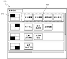
- FIG. 3 shows an example of a display information type selection screen. In the example of FIG. 3, an example of a division pattern in which the display screen is divided into four divided areas of left and right two divisions and upper and lower two divisions and displayed is shown.
- the display information type selection screen 300 includes at least a first display 310 that can visually specify the position of each divided area on the display screen.
- the first display 310 may be a display in which the size of each divided area on the display screen can be visually specified.
- the entire display screen is divided by a dividing line (dotted line), and the position of the divided area on the display screen is represented by the first display 310 in an icon format in which it is painted black.
- the display information type selection screen 300 includes at least a second display 320 showing a list of information types that can be displayed in each divided area. The second display 320 may be highlighted so that the information type currently displayed in the corresponding divided area can be grasped.
- the second display 320 may be highlighted so that the most recently selected information type can be grasped so as to be displayed in the divided area.
- the second display 320 is expressed in an icon format that displays the name of the information type.
- each divided area is related to the information type of "relative coordinates" in the upper left, "modal” in the upper right, "main axis, feed rate” in the lower left, and "machining program” in the lower right.
- the display of information is indicated by the icon being highlighted in a double frame.
- the first display 310 and the second display 320 corresponding to the same divided area are displayed so that the corresponding relationship can be grasped.
- the first display 310 and the second display 320 are displayed based on the correspondence between each divided area stored in the divided area display information type storage unit 210 and the information type assigned to the divided area.
- the first display 310 and the second display 320 corresponding to the same divided area are displayed side by side on the same line.
- the information types of "absolute coordinates", “relative coordinates", “machine coordinates”, and "comprehensive display” can be displayed in the upper left divided area.
- the display information type selection screen is configured so that it can be grasped at a glance which information type can be displayed in which division area.
- the display information type selection unit 120 executes a system program read from the ROM 12 by the CPU 11 included in the control device 1 shown in FIG. 1, mainly performs arithmetic processing using the RAM 13 and the non-volatile memory 14 by the CPU 11, and the interface 17, the interface 17. It is realized by performing the input / output process via 18.
- the display information type selection unit 120 accepts a selection operation for the second display 320, and determines a list of information types to be displayed in each divided area based on the selection operation. In the display information type selection screen 300 exemplified in FIG. 3, each information type included in the second display 320 can be selectively selected in the same second display 320, for example, a radio button. Has been done.
- the display information type selection unit 120 changes the information type selected by the operator to highlighting and is originally highlighted. Change the information type to normal display. Then, the display information type selection unit 120 instructs the display control unit 100 so that the display of the divided area corresponding to the second display performed by the operator is the information type selected by the selection operation. Further, the display information type selection unit 120 selects a division area when the division pattern to which the division area corresponding to the second display selected by the operator belongs is different from the currently displayed division pattern. Command the division pattern designation unit 130 to change to the division pattern to which the member belongs.
- the division pattern designation unit 130 is realized by executing a system program read from the ROM 12 by the CPU 11 included in the control device 1 shown in FIG. 1 and performing arithmetic processing mainly by the CPU 11 using the RAM 13 and the non-volatile memory 14. Will be done.
- the division pattern designation unit 130 designates a division pattern indicating how to divide the display screen of the display device 70 based on a command from the display information type selection unit 120.
- FIG. 4 shows an example of a display information type selection screen including a first display and a second display corresponding to a plurality of division patterns. As illustrated in FIG. 4, it is assumed that the display information type selection screen is displayed when the display screen is displayed based on the division pattern divided into left and right two divisions plus upper and lower two divisions.
- the display information type selection unit 120 displays the left and right 2 divisions.
- the division pattern designation unit 130 is instructed to change to the division pattern display of the division.
- the division pattern designation unit 130 receives this command and reads out the designated division pattern from the division pattern storage unit 220.
- the display control unit 100 is instructed to display the read division pattern.
- the display control unit 100 switches to the display in which the division pattern is changed, as illustrated in FIG.
- the control device 1 having the above configuration can display a list of information types that can be displayed in each divided area, and can freely select the information types to be displayed in each divided area, so that the visibility of the operator is improved.
- the burden on the work is reduced and the operation time is reduced.
- by making it possible to grasp at a glance the position on the display screen of each divided area and the information type displayed in each divided area a lot of information can be displayed while switching, such as setup work.
- it is necessary to display a plurality of related information types side by side according to the situation it is possible to organize the relationship between the position of the divided area where work can be performed efficiently and the information types that can be displayed.
- Control device 3 Industrial machinery 5 Network 6
- Fog computer 7 Cloud server 11
- PLC 19 I / O unit 22
- Bus 30 Axis control circuit 40
- Servo amplifier 50 Servo motor 70
- Display device 71 Input device 72
- External device 100
- Display control unit 110 Display information type selection screen Display unit 120
- Division pattern specification unit 200
- Information type storage unit 210 Divided area display Information type storage unit 220 Divided pattern storage unit
Abstract
制御装置は、表示画面を複数の領域に分割したそれら複数の分割領域のそれぞれについて、該分割領域の表示画面の上の位置を視覚的に特定できる第1の表示と、分割領域に表示可能な情報種別の一覧を示す第2の表示とを関連付けて一覧表示する表示情報種別選択画面を表示する。そして、第2の表示に含まれる情報種別に対する選択操作を受け付け、その選択操作に基づいて分割領域に表示する情報種別を選択し、その情報種別の選択に基づいて、複数の前記分割領域のそれぞれに所定の情報種別に係る情報を表示する。
Description
本発明は、制御装置に関する。
工作機械やロボットなどの産業用機械の操作を行う場合、例えば加工前の段取り作業における操作を行う場合、オペレータは、異なる種類の情報を確認しながら作業する。産業用機械を制御する制御装置は、複数の異なる種別の情報を1画面内で参照できるように、例えば表示装置の表示画面をタイル状の分割領域に区切り、それぞれの区切られた分割領域に異なる種別の情報を表示する機能を備える場合がある(特許文献1など)。
しかしながら、表示装置の表示画面のサイズや画素数には限界がある。そのため、特に段取り作業などのように1画面内に収まらないほどの情報量を表示する必要がある場合には、画面内の区切られた分割領域に表示する情報を切替えながら作業を行う必要がある。このような表示の切替えは、縦方向移動ソフトキー、横方向移動ソフトキー、機械操作盤などを操作することで行われる。
このように複数の分割領域に対して複数の情報種別を切り替えながら表示する場合、それぞれの分割領域にどのような情報種別を表示可能とするのかを予め定義しておき、その定義に従って表示の切り替えが行われる。しかしながら、縦方向移動ソフトキー、横方向移動ソフトキー、機械操作盤などを操作して切替えを行うと、どの分割領域に対してどの情報種別が表示されるのかが把握しにくく、目的とする表示に切り替えるのに手間がかかるという問題がある。また、段取り作業などでは、複数の情報種別を見比べながら作業することも多い。そのため、複数の分割領域のそれぞれに目的の情報種別を表示するために、切替え操作を試行錯誤する必要が出てくる。
このような問題に対応するために、それぞれの分割領域にどのような情報種別が切替え表示できるのか、全体を把握しながら操作可能な手段が望まれている。
このような問題に対応するために、それぞれの分割領域にどのような情報種別が切替え表示できるのか、全体を把握しながら操作可能な手段が望まれている。
本発明による制御装置は、1つの表示画面を複数の分割領域に分割して、それぞれの分割領域に対して異なる情報種別を表示可能な制御装置において、それぞれの分割領域に対して表示する情報種別を選択するユーザインタフェース画面を提供する。その画面では、それぞれの分割領域の表示画面上での位置と、該分割領域に表示可能な情報種別の一覧表示とが対応して表示される。この表示において所定の分割領域に表示する情報種別を選択することで、該分割領域の表示が選択した情報種別に切り替わる。オペレータは、各分割領域に表示可能な情報種別を一見して把握でき、所望の表示態様を簡単に選択することができる。
そして、本発明の一態様は、1つの表示画面を複数の分割領域に分割することが可能な制御装置であって、複数の前記分割領域のそれぞれについて、該分割領域の前記表示画面の上の位置を視覚的に特定できる第1の表示と、前記分割領域に表示可能な情報種別の一覧を示す第2の表示と、を関連付けて一覧表示する表示情報種別選択画面を表示する表示情報種別選択画面表示部と、前記第2の表示に含まれる情報種別に対する選択操作を受け付け、該選択操作に基づいて分割領域に表示する情報種別を選択する表示情報種別選択部と、前記表示情報種別選択部における情報種別の選択に基づいて、複数の前記分割領域のそれぞれに所定の情報種別に係る情報を表示する表示制御部と、制御装置である。
本発明の一態様により、各分割領域で表示可能な情報種別を一覧表示可能となり、また、各分割領域に表示する情報種別を自由に選択可能となるため、オペレータの視認性が向上し、作業に掛かる負担が軽減され、操作時間が削減される。
以下、本発明の実施形態を図面と共に説明する。
図1は本発明の第1実施形態による制御装置の要部を示す概略的なハードウェア構成図である。本発明の制御装置1は、例えば産業用機械3を制御用プログラムに基づいて制御する制御装置として実装することができる。
図1は本発明の第1実施形態による制御装置の要部を示す概略的なハードウェア構成図である。本発明の制御装置1は、例えば産業用機械3を制御用プログラムに基づいて制御する制御装置として実装することができる。
本実施形態による制御装置1が備えるCPU11は、制御装置1を全体的に制御するプロセッサである。CPU11は、バス22を介してROM12に格納されたシステム・プログラムを読み出し、該システム・プログラムに従って制御装置1全体を制御する。RAM13には一時的な計算データや表示データ、及び外部から入力された各種データ等が一時的に格納される。
不揮発性メモリ14は、例えばバッテリ(図示せず)でバックアップされたメモリやSSD(Solid State Drive)等で構成され、制御装置1の電源がオフされても記憶状態が保持される。不揮発性メモリ14には、インタフェース15を介して外部機器72から読み込まれた制御用プログラムやデータ、インタフェース18を介して入力装置71から入力された制御用プログラムやデータ、ネットワーク5を介してフォグコンピュータ6やクラウドサーバ7等の他の装置から取得された制御用プログラムやデータ等が記憶される。不揮発性メモリ14に記憶されるデータは、例えば産業用機械3が備える各モータの位置や速度、加速度、負荷、その他の産業用機械3に取り付けられた図示しないセンサで検出された各物理量に係るデータ等が含まれていてよい。不揮発性メモリ14に記憶された制御用プログラムやデータは、実行時/利用時にはRAM13に展開されてもよい。また、ROM12には、公知の解析プログラムなどの各種システム・プログラムがあらかじめ書き込まれている。
インタフェース15は、制御装置1のCPU11と外部記憶媒体等の外部機器72と接続するためのインタフェースである。外部機器72側からは、例えば産業用機械3の制御に用いられる制御用プログラムや設定データ等が読み込まれる。また、制御装置1内で編集した制御用プログラムや設定データ等は、外部機器72を介してCFカードやUSBメモリ等の外部記憶媒体(図示せず)に記憶させることができる。プログラマブル・ロジック・コントローラ(PLC)16は、ラダープログラムを実行して産業用機械3及び該産業用機械3の周辺装置(例えば、工具交換装置や、ロボット等のアクチュエータ、産業用機械3に取付けられている温度センサや湿度センサ等のセンサ)にI/Oユニット19を介して信号を出力し制御する。また、産業用機械3の本体に配備された操作盤の各種スイッチや周辺装置等の信号を受け取り、それに必要な信号処理をした後、CPU11に渡す。
インタフェース20は、制御装置1のCPUと有線乃至無線のネットワーク5とを接続するためのインタフェースである。ネットワーク5は、例えばRS-485等のシリアル通信、Ethernet(登録商標)通信、光通信、無線LAN、Wi-Fi(登録商標)、Bluetooth(登録商標)等の技術を用いて通信をするものであってよい。ネットワーク5には、他の機械やフォグコンピュータ6、クラウドサーバ7等の上位の管理装置が接続され、制御装置1との間で相互にデータのやり取りを行っている。
表示装置70には、メモリ上に読み込まれた各データ、プログラム等が実行された結果として得られたデータ等がインタフェース17を介して出力されて表示される。表示装置70は、その表示能力に係る情報(例えば、表示サイズ、画素数など)が制御装置1から取得可能であることが望ましい。取得された表示能力に係る情報は、逐次取得するようにしてもよいし、他の情報と同様にRAM13、不揮発性メモリ14に記憶してもよい。また、キーボードやポインティングデバイス等から構成される入力装置71は、作業者による操作に基づく指令,データ等をインタフェース18を介してCPU11に渡す。
産業用機械3が備える軸を制御するための軸制御回路30はCPU11からの軸の移動指令量を受け取って、軸の指令をサーボアンプ40にそれぞれ出力する。サーボアンプ40はこの指令を受け取って、産業用機械3が備える駆動部を軸に沿って移動させるサーボモータ50をそれぞれ駆動する。軸のサーボモータ50は位置・速度検出器を内蔵し、この位置・速度検出器からの位置・速度フィードバック信号を軸制御回路30にそれぞれフィードバックし、位置・速度のフィードバック制御を行う。なお、図1のハードウェア構成図では軸制御回路30、サーボアンプ40、サーボモータ50はそれぞれ1つずつしか示されていないが、実際には制御対象となる産業用機械3に備えられた軸の数だけ用意される。
図2は、本発明の第1実施形態による制御装置1が備える機能を概略的なブロック図として示したものである。本実施形態による制御装置1が備える各機能は、図1に示した制御装置1が備えるCPU11がシステム・プログラムを実行し、制御装置1の各部の動作を制御することにより実現される。
本実施形態の制御装置1は、表示制御部100、表示情報種別選択画面表示部110、表示情報種別選択部120、及び分割パターン指定部130を備える。また、制御装置1のRAM13乃至不揮発性メモリ14には、制御装置1で表示可能な情報種別を識別する情報(例えば情報種別の名称、情報種別に係る情報を表示するための表示プログラムへのポインタなど)を少なくとも記憶する情報種別記憶部200、それぞれの分割領域毎に該分割領域に割り当てられて表示可能となっている情報種別が関連付けられて記憶されている領域である分割領域表示情報種別記憶部210、表示装置70の表示画面をどのように分割するのかを示す分割パターンが予め記憶されている領域である分割パターン記憶部220がそれぞれ設けられている。
表示制御部100は、図1に示した制御装置1が備えるCPU11がROM12から読み出したシステム・プログラムを実行し、主としてCPU11によるRAM13、不揮発性メモリ14を用いた演算処理と、インタフェース17を用いた表示出力処理とが行われることで実現される。表示制御部100は、表示装置70の表示画面を複数の分割領域に分割し、それぞれの分割領域に指定された情報種別に係る情報を表示する。表示制御部100は、情報種別に係る情報を表示する際、情報種別記憶部200を参照して、表示する情報種別に対応する表示プログラムを呼び出す。表示制御部100は、通常は表示装置70の表示画面を1つの表示領域として扱い、該表示領域に対してオペレータの操作により決定された所定の情報種別に係る情報を表示する。また、表示制御部100は、分割パターン指定部130により表示画面の分割が指定されると、表示画面を指定された分割パターンに基づいて複数の分割領域に分割する。そして、それぞれの分割領域に、分割領域表示情報種別記憶部210に記憶される所定の情報種別に係る情報を表示する。
表示情報種別選択画面表示部110は、図1に示した制御装置1が備えるCPU11がROM12から読み出したシステム・プログラムを実行し、主としてCPU11によるRAM13、不揮発性メモリ14を用いた演算処理と、インタフェース17を介した表示出力処理が行われることで実現される。表示情報種別選択画面表示部110は、表示装置70の表示画面に表示情報種別選択画面を表示する。
図3は、表示情報種別選択画面の一例を示している。図3の例では、表示画面を左右2分割、上下2分割の4つの分割領域に分割して表示する分割パターンの例を示している。
表示情報種別選択画面300は、少なくとも各分割領域の表示画面上における位置を視覚的に特定できる第1の表示310を含む。第1の表示310は、更に各分割領域の表示画面上における大きさを視覚的に特定できる表示としても良い。図3の例では、表示画面全体を分割線(点線)で分割し、表示画面上における分割領域の位置を黒塗りしたアイコン形式で第1の表示310を表現している。
また、表示情報種別選択画面300は、少なくとも各分割領域に表示可能な情報種別の一覧を示す第2の表示320を含む。第2の表示320は、該当する分割領域に現在表示されている情報種別が把握できるように強調表示してもよい。また、第2の表示320は、分割領域に表示するように最も最近選択された情報種別が把握できるように強調表示してもよい。図3の例では、情報種別の名称を表示するアイコン形式で第2の表示320を表現している。
また、それぞれの分割領域には、図3に示すように、左上に「相対座標」、右上に「モーダル」、左下に「主軸、送り速度」、右下に「加工プログラム」の情報種別に係る情報が表示されていることが、アイコンが2重枠で強調表示されることで示されている。同じ分割領域に対応する第1の表示310と第2の表示320とは、その対応関係が把握できるように表示される。第1の表示310及び第2の表示320は、分割領域表示情報種別記憶部210に記憶された、各分割領域と、該分割領域に割り当てられている情報種別との対応関係に基づいて表示される。例えば図3の例では、同じ分割領域に対応する第1の表示310と第2の表示320とが同じ行に横並びに表示されている。この例では、左上の分割領域には、「絶対座標」、「相対座標」、「機械座標」、「総合表示」の情報種別が表示可能となっている。このように、表示情報種別選択画面では、どの分割領域に、どの情報種別が表示可能であるのかが、一見して把握できるように構成される。
表示情報種別選択部120は、図1に示した制御装置1が備えるCPU11がROM12から読み出したシステム・プログラムを実行し、主としてCPU11によるRAM13、不揮発性メモリ14を用いた演算処理と、インタフェース17,18を介した入出力処理が行われることで実現される。表示情報種別選択部120は、第2の表示320に対する選択操作を受け付け、該選択操作に基づいてそれぞれの分割領域に表示する情報種別の一覧を決定する。
図3に例示される表示情報種別選択画面300において、第2の表示320に含まれるそれぞれの情報種別は、例えばラジオボタンのように同じ第2の表示320内で択一的に選択可能に構成されている。オペレータがマウス等を操作して、第2の表示320に含まれる情報種別を選択すると、表示情報種別選択部120は、オペレータが選択した情報種別を強調表示へと変更し、元々強調表示されていた情報種別を通常の表示に変更する。そして、表示情報種別選択部120は、オペレータが選択操作をした第2表示に対応する分割領域の表示が、該選択操作で選択された情報種別とするように表示制御部100へと指令する。また、表示情報種別選択部120は、オペレータが選択操作をした第2表示に対応する分割領域が属する分割パターンが、現在表示されている分割パターンと異なるものであった場合に、選択した分割領域が属する分割パターンへと変更するように分割パターン指定部130へと指令する。
図3に例示される表示情報種別選択画面300において、第2の表示320に含まれるそれぞれの情報種別は、例えばラジオボタンのように同じ第2の表示320内で択一的に選択可能に構成されている。オペレータがマウス等を操作して、第2の表示320に含まれる情報種別を選択すると、表示情報種別選択部120は、オペレータが選択した情報種別を強調表示へと変更し、元々強調表示されていた情報種別を通常の表示に変更する。そして、表示情報種別選択部120は、オペレータが選択操作をした第2表示に対応する分割領域の表示が、該選択操作で選択された情報種別とするように表示制御部100へと指令する。また、表示情報種別選択部120は、オペレータが選択操作をした第2表示に対応する分割領域が属する分割パターンが、現在表示されている分割パターンと異なるものであった場合に、選択した分割領域が属する分割パターンへと変更するように分割パターン指定部130へと指令する。
分割パターン指定部130は、図1に示した制御装置1が備えるCPU11がROM12から読み出したシステム・プログラムを実行し、主としてCPU11によるRAM13、不揮発性メモリ14を用いた演算処理が行われることで実現される。分割パターン指定部130は、表示情報種別選択部120からの指令に基づいて、表示装置70の表示画面をどのように分割するのかを示す分割パターンを指定する。
図4は、複数の分割パターンに対応する第1の表示および第2の表示を含む表示情報種別選択画面の例を示している。図4に例示するように、表示画面が左右2分割プラス上下2分割に分割された分割パターンに基づいた表示がされているときに、表示情報種別選択画面を表示したとする。この時、表示情報種別選択画面の中から、現在表示されている分割パターンと異なる左右2分割の分割パターンに属する分割領域に表示する情報種別を選択すると、表示情報種別選択部120は、左右2分割の分割パターン表示へと変更するように分割パターン指定部130に指令する。分割パターン指定部130は、この指令を受け取って、分割パターン記憶部220から指定された分割パターンを読み出す。そして、読み出した分割パターンで表示するように表示制御部100に指令する。この指令を受け取って、表示制御部100は、図5に例示するように、分割パターンを変更した表示に切り替える。
図4は、複数の分割パターンに対応する第1の表示および第2の表示を含む表示情報種別選択画面の例を示している。図4に例示するように、表示画面が左右2分割プラス上下2分割に分割された分割パターンに基づいた表示がされているときに、表示情報種別選択画面を表示したとする。この時、表示情報種別選択画面の中から、現在表示されている分割パターンと異なる左右2分割の分割パターンに属する分割領域に表示する情報種別を選択すると、表示情報種別選択部120は、左右2分割の分割パターン表示へと変更するように分割パターン指定部130に指令する。分割パターン指定部130は、この指令を受け取って、分割パターン記憶部220から指定された分割パターンを読み出す。そして、読み出した分割パターンで表示するように表示制御部100に指令する。この指令を受け取って、表示制御部100は、図5に例示するように、分割パターンを変更した表示に切り替える。
上記構成を備えた制御装置1は、各分割領域で表示可能な情報種別を一覧表示可能となり、また、各分割領域に表示する情報種別を自由に選択可能となるため、オペレータの視認性が向上し、作業に掛かる負担が軽減され、操作時間が削減される。特に、それぞれの分割領域の表示画面上の位置と、各分割領域に表示される情報種別とを一見して把握できるようにしたことで、段取り作業などのように多くの情報を切り替えながら表示しつつ、状況に応じて関連性のある複数の情報種別を並べて表示する必要がある場合に、効率よく作業できる分割領域の位置と表示可能な情報種別との関係を整理することが可能となる。
以上、本発明の一実施形態について説明したが、本発明は上述した実施の形態の例のみに限定されることなく、適宜の変更を加えることにより様々な態様で実施することができる。
1 制御装置
3 産業用機械
5 ネットワーク
6 フォグコンピュータ
7 クラウドサーバ
11 CPU
12 ROM
13 RAM
14 不揮発性メモリ
15,17,18,20 インタフェース
16 PLC
19 I/Oユニット
22 バス
30 軸制御回路
40 サーボアンプ
50 サーボモータ
70 表示装置
71 入力装置
72 外部機器
100 表示制御部
110 表示情報種別選択画面表示部
120 表示情報種別選択部
130 分割パターン指定部
200 情報種別記憶部
210 分割領域表示情報種別記憶部
220 分割パターン記憶部
3 産業用機械
5 ネットワーク
6 フォグコンピュータ
7 クラウドサーバ
11 CPU
12 ROM
13 RAM
14 不揮発性メモリ
15,17,18,20 インタフェース
16 PLC
19 I/Oユニット
22 バス
30 軸制御回路
40 サーボアンプ
50 サーボモータ
70 表示装置
71 入力装置
72 外部機器
100 表示制御部
110 表示情報種別選択画面表示部
120 表示情報種別選択部
130 分割パターン指定部
200 情報種別記憶部
210 分割領域表示情報種別記憶部
220 分割パターン記憶部
Claims (4)
- 1つの表示画面を複数の分割領域に分割することが可能な制御装置であって、
複数の前記分割領域のそれぞれについて、該分割領域の前記表示画面の上の位置を視覚的に特定できる第1の表示と、前記分割領域に表示可能な情報種別の一覧を示す第2の表示と、を関連付けて一覧表示する表示情報種別選択画面を表示する表示情報種別選択画面表示部と、
前記第2の表示に含まれる情報種別に対する選択操作を受け付け、該選択操作に基づいて分割領域に表示する情報種別を選択する表示情報種別選択部と、
前記表示情報種別選択部における情報種別の選択に基づいて、複数の前記分割領域のそれぞれに所定の情報種別にかかる情報を表示する表示制御部と、
制御装置。 - さらに、前記表示情報種別選択部における情報種別の選択に基づいて前記表示画面の分割パターンを指定する分割パターン指定部を備え、
前記表示制御部は、前記分割パターン指定部が指定した分割パターンに基づいて、前記表示画面を複数の分割領域に分割する、
請求項1に記載された制御装置。 - 前記第1の表示は、分割領域の前記表示画面の上での位置を示すアイコン表示である、請求項1に記載の制御装置。
- 前記第2の表示は、前記表示制御部により分割領域に表示されている情報種別が把握できるように強調表示する、請求項1に記載の制御装置。
Priority Applications (4)
| Application Number | Priority Date | Filing Date | Title |
|---|---|---|---|
| DE112021004864.3T DE112021004864T5 (de) | 2020-11-20 | 2021-11-17 | Steuerung |
| US18/035,183 US20230409004A1 (en) | 2020-11-20 | 2021-11-17 | Controller |
| CN202180075204.XA CN116420120A (zh) | 2020-11-20 | 2021-11-17 | 控制装置 |
| JP2022563805A JPWO2022107818A1 (ja) | 2020-11-20 | 2021-11-17 |
Applications Claiming Priority (2)
| Application Number | Priority Date | Filing Date | Title |
|---|---|---|---|
| JP2020-193517 | 2020-11-20 | ||
| JP2020193517 | 2020-11-20 |
Publications (1)
| Publication Number | Publication Date |
|---|---|
| WO2022107818A1 true WO2022107818A1 (ja) | 2022-05-27 |
Family
ID=81708989
Family Applications (1)
| Application Number | Title | Priority Date | Filing Date |
|---|---|---|---|
| PCT/JP2021/042261 WO2022107818A1 (ja) | 2020-11-20 | 2021-11-17 | 制御装置 |
Country Status (5)
| Country | Link |
|---|---|
| US (1) | US20230409004A1 (ja) |
| JP (1) | JPWO2022107818A1 (ja) |
| CN (1) | CN116420120A (ja) |
| DE (1) | DE112021004864T5 (ja) |
| WO (1) | WO2022107818A1 (ja) |
Citations (2)
| Publication number | Priority date | Publication date | Assignee | Title |
|---|---|---|---|---|
| JP2010120095A (ja) * | 2008-11-17 | 2010-06-03 | Yaskawa Electric Corp | ロボットシステム |
| WO2015194010A1 (ja) * | 2014-06-19 | 2015-12-23 | 株式会社牧野フライス製作所 | 工作機械の制御装置 |
Family Cites Families (1)
| Publication number | Priority date | Publication date | Assignee | Title |
|---|---|---|---|---|
| JP4105303B2 (ja) | 1998-08-20 | 2008-06-25 | 株式会社森精機製作所 | Nc工作機械における表示装置 |
-
2021
- 2021-11-17 US US18/035,183 patent/US20230409004A1/en active Pending
- 2021-11-17 CN CN202180075204.XA patent/CN116420120A/zh active Pending
- 2021-11-17 WO PCT/JP2021/042261 patent/WO2022107818A1/ja active Application Filing
- 2021-11-17 DE DE112021004864.3T patent/DE112021004864T5/de active Pending
- 2021-11-17 JP JP2022563805A patent/JPWO2022107818A1/ja active Pending
Patent Citations (2)
| Publication number | Priority date | Publication date | Assignee | Title |
|---|---|---|---|---|
| JP2010120095A (ja) * | 2008-11-17 | 2010-06-03 | Yaskawa Electric Corp | ロボットシステム |
| WO2015194010A1 (ja) * | 2014-06-19 | 2015-12-23 | 株式会社牧野フライス製作所 | 工作機械の制御装置 |
Also Published As
| Publication number | Publication date |
|---|---|
| DE112021004864T5 (de) | 2023-08-03 |
| US20230409004A1 (en) | 2023-12-21 |
| JPWO2022107818A1 (ja) | 2022-05-27 |
| CN116420120A (zh) | 2023-07-11 |
Similar Documents
| Publication | Publication Date | Title |
|---|---|---|
| US8190287B2 (en) | Tool vector display apparatus for a machine tool with rotational axes | |
| WO2016051544A1 (ja) | 工作機械の制御装置 | |
| CN105637438A (zh) | 多轴控制系统设定及调整功能辅助装置 | |
| JP2019188558A (ja) | 工具選定装置及び機械学習装置 | |
| CN105938411B (zh) | 控制面板 | |
| CN112147949B (zh) | 参数管理装置及其管理系统 | |
| WO2022107818A1 (ja) | 制御装置 | |
| JP4329805B2 (ja) | 動作制御操作盤 | |
| US10705489B2 (en) | Controller | |
| WO2022107822A1 (ja) | 制御装置 | |
| US20190033825A1 (en) | Parameter setting support device | |
| JPH0822313A (ja) | 数値制御装置 | |
| JP3079973U (ja) | 機械モニター画面の構成 | |
| WO2023228327A1 (ja) | 制御装置 | |
| WO2022107817A1 (ja) | 制御装置 | |
| EP2994800B1 (en) | A method for providing presentation of tactile feedback, an industrial robot system and a portable operator control device | |
| US20230072717A1 (en) | Display control system | |
| WO2022249304A1 (ja) | 産業機械の制御装置 | |
| JP4023051B2 (ja) | 動作制御操作盤 | |
| WO2022102581A1 (ja) | 制御装置 | |
| WO2021241436A1 (ja) | 制御装置、及び制御方法 | |
| US10921978B2 (en) | Shaft feeder | |
| WO2022249305A1 (ja) | 産業機械の制御装置 | |
| JP2779796B2 (ja) | 数値制御装置 | |
| JP2694639B2 (ja) | 数値制御装置 |
Legal Events
| Date | Code | Title | Description |
|---|---|---|---|
| 121 | Ep: the epo has been informed by wipo that ep was designated in this application |
Ref document number: 21894691 Country of ref document: EP Kind code of ref document: A1 |
|
| ENP | Entry into the national phase |
Ref document number: 2022563805 Country of ref document: JP Kind code of ref document: A |
|
| 122 | Ep: pct application non-entry in european phase |
Ref document number: 21894691 Country of ref document: EP Kind code of ref document: A1 |