WO2022107582A1 - Dispositif de traitement d'informations, procédé de traitement d'informations, support d'enregistrement lisible par ordinateur et procédé de génération de modèle - Google Patents
Dispositif de traitement d'informations, procédé de traitement d'informations, support d'enregistrement lisible par ordinateur et procédé de génération de modèle Download PDFInfo
- Publication number
- WO2022107582A1 WO2022107582A1 PCT/JP2021/040244 JP2021040244W WO2022107582A1 WO 2022107582 A1 WO2022107582 A1 WO 2022107582A1 JP 2021040244 W JP2021040244 W JP 2021040244W WO 2022107582 A1 WO2022107582 A1 WO 2022107582A1
- Authority
- WO
- WIPO (PCT)
- Prior art keywords
- change
- visual
- information processing
- input
- latent space
- Prior art date
Links
- 230000010365 information processing Effects 0.000 title claims abstract description 87
- 238000000034 method Methods 0.000 title claims description 128
- 238000003672 processing method Methods 0.000 title claims description 13
- 230000008859 change Effects 0.000 claims abstract description 602
- 230000000007 visual effect Effects 0.000 claims abstract description 335
- 230000001149 cognitive effect Effects 0.000 claims description 153
- 238000001514 detection method Methods 0.000 claims description 133
- 230000008569 process Effects 0.000 claims description 95
- 238000012360 testing method Methods 0.000 claims description 55
- 201000004569 Blindness Diseases 0.000 claims description 30
- 241000282414 Homo sapiens Species 0.000 claims description 19
- 238000013459 approach Methods 0.000 claims description 5
- 238000005516 engineering process Methods 0.000 abstract description 13
- 238000012545 processing Methods 0.000 description 46
- 238000010586 diagram Methods 0.000 description 31
- 238000004891 communication Methods 0.000 description 29
- 238000012937 correction Methods 0.000 description 23
- 238000002474 experimental method Methods 0.000 description 19
- 238000004364 calculation method Methods 0.000 description 12
- 238000005457 optimization Methods 0.000 description 11
- 238000004458 analytical method Methods 0.000 description 10
- 230000006870 function Effects 0.000 description 8
- 238000013461 design Methods 0.000 description 7
- 235000013305 food Nutrition 0.000 description 6
- 230000019771 cognition Effects 0.000 description 5
- 241000282412 Homo Species 0.000 description 3
- 238000010801 machine learning Methods 0.000 description 3
- 230000015654 memory Effects 0.000 description 3
- 230000006403 short-term memory Effects 0.000 description 3
- 230000007704 transition Effects 0.000 description 3
- 125000002066 L-histidyl group Chemical group [H]N1C([H])=NC(C([H])([H])[C@](C(=O)[*])([H])N([H])[H])=C1[H] 0.000 description 2
- 239000004973 liquid crystal related substance Substances 0.000 description 2
- 230000008685 targeting Effects 0.000 description 2
- 230000001052 transient effect Effects 0.000 description 2
- 241001465754 Metazoa Species 0.000 description 1
- 208000003443 Unconsciousness Diseases 0.000 description 1
- 210000004556 brain Anatomy 0.000 description 1
- 238000010411 cooking Methods 0.000 description 1
- 239000002537 cosmetic Substances 0.000 description 1
- 230000007423 decrease Effects 0.000 description 1
- 238000013135 deep learning Methods 0.000 description 1
- 230000008034 disappearance Effects 0.000 description 1
- 230000000694 effects Effects 0.000 description 1
- 230000001815 facial effect Effects 0.000 description 1
- 230000001151 other effect Effects 0.000 description 1
- 239000002245 particle Substances 0.000 description 1
- 230000008447 perception Effects 0.000 description 1
- 230000004044 response Effects 0.000 description 1
- 239000007787 solid Substances 0.000 description 1
- 230000009012 visual motion Effects 0.000 description 1
Images


Classifications
-
- G—PHYSICS
- G06—COMPUTING; CALCULATING OR COUNTING
- G06F—ELECTRIC DIGITAL DATA PROCESSING
- G06F3/00—Input arrangements for transferring data to be processed into a form capable of being handled by the computer; Output arrangements for transferring data from processing unit to output unit, e.g. interface arrangements
- G06F3/01—Input arrangements or combined input and output arrangements for interaction between user and computer
- G06F3/011—Arrangements for interaction with the human body, e.g. for user immersion in virtual reality
- G06F3/013—Eye tracking input arrangements
-
- G—PHYSICS
- G09—EDUCATION; CRYPTOGRAPHY; DISPLAY; ADVERTISING; SEALS
- G09G—ARRANGEMENTS OR CIRCUITS FOR CONTROL OF INDICATING DEVICES USING STATIC MEANS TO PRESENT VARIABLE INFORMATION
- G09G5/00—Control arrangements or circuits for visual indicators common to cathode-ray tube indicators and other visual indicators
-
- G—PHYSICS
- G02—OPTICS
- G02B—OPTICAL ELEMENTS, SYSTEMS OR APPARATUS
- G02B27/00—Optical systems or apparatus not provided for by any of the groups G02B1/00 - G02B26/00, G02B30/00
- G02B27/0093—Optical systems or apparatus not provided for by any of the groups G02B1/00 - G02B26/00, G02B30/00 with means for monitoring data relating to the user, e.g. head-tracking, eye-tracking
Definitions
- This technique relates to an information processing device, an information processing method, a computer-readable recording medium, and a model generation method that can be applied to the generation of contents whose display contents change.
- Patent Document 1 describes a method of changing a display object displayed to a communication partner when performing remote communication.
- a photographed image of a space in which one is present is displayed on the other side as a display object.
- the other party is not gazing at the display object, the appearance of the display object is corrected. This makes it possible to decorate the space in which one is present and oneself without being noticed by the other party (paragraphs [0025] [0054] [0058] of FIG. 6 of Patent Document 1 and the like).
- the purpose of the present technology is to provide an information processing device, an information processing method, a computer-readable recording medium, and a model that realize content whose display content changes so as not to be noticed by the user. It is to provide a generation method.
- the information processing apparatus includes an acquisition unit and an output unit.
- the acquisition unit acquires data regarding an input object which is a visual object.
- the output unit responds to instruction information including an instruction value regarding the recognition degree based on a model representing a relationship between a distance in a latent space regarding the visual object and a recognition degree for a change of the visual object according to the distance.
- data or cognitive parameters related to the change object are output using a model in which the degree of recognition of the change of the visual object is associated with the distance in the latent space.
- the change object is an object in which the input object is changed according to the instruction information of the degree of recognition.
- the cognitive parameter is a value indicating the degree of recognition of the change from the input object to the reference object.
- the indicated value may be the threshold value of the degree of recognition.
- the at least one change object may be an object that is switched and displayed in a predetermined order instead of the input object.
- the output unit switches and displays the change object so that the recognition degree for the visual change caused by switching and displaying the change object does not exceed the threshold value of the recognition degree.
- the distance in the latent space corresponding to the amount of change in the target change is set.
- the output unit maximizes the distance in the latent space corresponding to the amount of change within the range in which the degree of recognition for the visual change caused by switching and displaying the change object does not exceed the threshold value of the degree of recognition. It may be set to a value.
- the predetermined order may be an order in which the distance between the input object and the change object in the latent space is short.
- the output unit may output data regarding the at least one change object in which the input object is changed so as to approach the reference object corresponding to the input object in the latent space.
- the instruction information may include information indicating a change direction in the latent space that changes the input object.
- the output unit may output data regarding the at least one change object in which the input object is changed along the change direction in the latent space.
- the latent space may be a feature space composed of at least one feature related to the visual object.
- the instruction information may be information that indicates the change direction by at least one of the feature quantities.
- the information processing device further controls the display device so as to display the target object to be displayed among the input object and the at least one change object, and visually changes the user who sees the target object.
- a display control unit that detects a state that causes blindness and controls the display device so as to change the target object to the change object to be displayed next in accordance with the timing when the visual change blindness occurs. May be provided.
- the state of causing the visual change blindness is at least one of a state in which the user closes his eyes, a state in which the display of the target object is obstructed, and a state in which the display parameters of the target object are changed. It may be included.
- the output unit may output a change detection rate for an overall visual change caused by changing the input object to the reference object.
- the output unit may output a first change detection rate for a visual change accompanying a first change process that changes the input object into the reference object at once.
- the output unit outputs a second change detection rate for a visual change accompanying the second change process including a plurality of divided change processes for changing the input object to the reference object in a plurality of times. good.
- the output unit may calculate the second change detection rate by multiplying the division change detection rate for the visual change associated with each of the plurality of division change processes.
- the acquisition unit acquires the threshold value of the second change detection rate, and obtains the threshold value.
- the output unit sets the number of times of the plurality of divided change processes and the amount of change in each of the plurality of divided change processes so that the second change detection rate is equal to or less than the threshold value of the second change detection rate. You may.
- the reference object may be either an object input by the user or an object obtained by changing the input object according to the amount of change input by the user.
- the model may include a plurality of graph data showing the degree of recognition of the visual object according to the distance in the latent space in each of the different directions of change in the latent space.
- the plurality of graph data may include data generated for each human characteristic.
- the output unit may select data that matches the characteristics of the user from the plurality of graph data.
- the information processing method is an information processing method executed by a computer system and includes acquiring data relating to an input object which is a visual object. Based on a model showing the relationship between the distance in the latent space of the visual object and the degree of recognition of the change of the visual object according to the distance, in the latent space according to the instruction information including the instruction value regarding the degree of recognition. Data on at least one change object that has changed the input object, or at least one of the cognitive parameters representing the degree of recognition of the change from the input object to the reference object corresponding to the input object is output.
- a computer-readable recording medium records a program that causes a computer system to perform the following steps.
- the model generation method is a model generation method executed by a computer system, in which a first visual object and a second visual sense are represented by different points in a latent space regarding a visual object. Includes generating data for each of the objects.
- the determination result of the test that causes the examiner to determine the presence or absence of a cognitive difference between the first and second visual objects or the degree of the cognitive difference, and the first and second visual objects.
- Data associated with the distance of the represented point in the latent space is acquired. Based on the acquired data, a model showing the relationship between the distance in the latent space and the degree of recognition of the change of the visual object according to the distance is generated.
- FIG. 1 is a schematic diagram showing an outline of a content generation system according to an embodiment of the present technology.
- the content generation system 100 is a system that generates visual content 10 that presents various visual information to the user 1.
- the visual content 10 includes a visual object 2 that can be visually viewed by the user 1.
- a visually visible object such as a photograph, graphics, characters, or a drawing is a visual object 2.
- the visual content 10 is configured by combining these visual objects 2.
- the visual content 10 including a person image and characters is displayed on the display 20 as the visual object 2.
- the content generation system 100 generates visual content 10 in which the visual object 2 which is the display content changes.
- the input object 3 female person image
- the input object 3 is a visual object 2 to be processed by the content generation system 100.
- a process of visually changing the input object 3 is performed.
- the reference object 5 male person image
- the reference object 5 male person image
- the display of each object is switched, for example, at the timing when the visual change blindness that makes it difficult for the user 1 to recognize the visual change occurs. This makes it possible to change the display content so that the user 1 does not notice it.
- the visual change blindness will be described in detail later.
- the data related to each change object 4 in which the input object 3 is changed is output using the latent space related to the visual object 2.
- the latent space is, for example, a high-dimensional vector space composed of a large number of latent variables representing the visual object 2. Each point in the latent space corresponds to a visual object 2 with a different latent variable.
- a latent space that represents the input object 3, that is, a point corresponding to the input object 3 can be set is used.
- an image visual object 2 representing a similar motif (person, landscape, food, etc.
- the data related to the change object 4 is output using the latent space corresponding to the motif of the input object 3.
- a latent space related to a person image is used. It is not always necessary to construct the latent space separately for each motif, and for example, a general-purpose latent space capable of representing the entire image may be used. Further, a latent space corresponding to the type of the visual object 2 (photograph, graphics, characters, drawings, etc.) may be used, or a latent space including each type may be used.
- the input object 3 changes by moving the point corresponding to the input object 3 in the latent space.
- the amount of change is the distance moved by the point corresponding to the input object 3. Therefore, the amount of change in the visual change caused by switching and displaying the change object 4 (that is, the amount of change in the visual change before and after the change) can be expressed as a distance in the latent space.
- visual content is generated using a model showing the relationship between the distance in the latent space of the visual object 2 and the degree of recognition of the change of the visual object 2 according to the distance.
- this model is a scale that defines the degree of recognition of the visual object 2 for the visual change by using the distance in the latent space with respect to the visual object 2.
- this model will be referred to as the Latent Cognitive Scale.
- the latent cognitive scale By using the latent cognitive scale, it is possible to output data related to the change object 4 in which the degree of recognition for visual changes due to object switching is controlled, and to predict the degree of recognition for visual changes due to object switching. Is possible.
- the latent space and the latent cognitive scale will be described in detail later.
- FIG. 2 is a block diagram showing a configuration example of a content generation system.
- the content generation system 100 includes a display 20, an operation input unit 21, a shooting unit 22, a communication unit 23, a storage unit 24, and a controller 25.
- the display 20 is a display device for displaying an image. Data on the content screen generated by the controller 25, which will be described later, is input to the display 20.
- the content screen is a screen for displaying the visual content 10.
- the content screen includes various visual objects 2.
- the visual object 2 displayed on the content screen (display 20) is referred to as a display object.
- the display 20 for example, an LCD (Liquid Crystal Display) including a liquid crystal display element, an organic EL display, or the like is used.
- the specific configuration of the display 20 is not limited. In this embodiment, the display 20 corresponds to a display device.
- the operation input unit 21 is an input device that accepts the operation input of the user 1.
- the user 1 can operate the operation input unit 21 to operate the content screen and input various data.
- the operation input unit 21 for example, a mouse, a keyboard, or the like is used.
- a touch panel, a line-of-sight input device, or the like may be used.
- the photographing unit 22 is a camera that photographs the user 1.
- the photographing unit 22 is provided, for example, on the outer edge portion of the display 20. Alternatively, apart from the display 20, a photographing unit 22 configured as a single device may be used. In this case, the photographing unit 22 is provided at a position where the user 1 can be photographed from the front.
- a digital camera equipped with an image sensor such as CMOS or CCD is used as the photographing unit 22 a digital camera equipped with an image sensor such as CMOS or CCD is used.
- the communication unit 23 is a module for executing network communication, short-range wireless communication, etc. with other devices.
- a wireless LAN module such as WiFi
- a communication module such as Bluetooth (registered trademark) are provided.
- a communication module or the like capable of communication by a wired connection may be provided.
- the storage unit 24 is a non-volatile storage device.
- a recording medium using a solid-state element such as an SSD (Solid State Drive) or a magnetic recording medium such as an HDD (Hard Disk Drive) is used.
- the type of recording medium used as the storage unit 24 is not limited, and for example, any recording medium for recording data non-temporarily may be used.
- the control program according to the present embodiment is stored in the storage unit 24.
- the control program is, for example, a program that controls the operation of the entire content generation system 100.
- the storage unit 24 stores data of various visual objects 2 constituting visual contents and data of the above-mentioned latent cognitive scale.
- the information stored in the storage unit 24 is not limited.
- the storage unit 24 corresponds to a computer-readable recording medium on which the program is recorded.
- the control program corresponds to the program recorded on the recording medium.
- the controller 25 controls the operation of the content generation system 100.
- the controller 25 has a hardware configuration necessary for a computer such as a CPU and a memory (RAM, ROM). Various processes are executed by the CPU loading the control program stored in the storage unit 24 into the RAM and executing the control program.
- the controller 25 corresponds to the information processing device according to the present embodiment.
- controller 25 for example, a device such as a PLD (Programmable Logic Device) such as an FPGA (Field Programmable Gate Array) or another device such as an ASIC (Application Specific Integrated Circuit) may be used. Further, for example, a processor such as a GPU (Graphics Processing Unit) may be used as the controller 25.
- a PLD Processable Logic Device
- FPGA Field Programmable Gate Array
- ASIC Application Specific Integrated Circuit
- a processor such as a GPU (Graphics Processing Unit) may be used as the controller 25.
- the CPU of the controller 25 executes the program (control program) according to the present embodiment, so that the data acquisition unit 26, the object processing unit 27, and the display control unit 28 are realized as functional blocks. Then, the information processing method according to the present embodiment is executed by these functional blocks.
- dedicated hardware such as an IC (integrated circuit) may be appropriately used.
- the data acquisition unit 26 acquires various data necessary for generating the visual content 10. For example, the data stored in the storage unit 24, the set value, and the like are read. Further, for example, data, setting values, and the like input by the user 1 on the content screen or the like using the operation input unit 21 are read. Further, for example, data values or the like for generating the visual content 10 from another device may be read via the network to which the communication unit 23 is connected.
- the data acquisition unit 26 acquires data related to the input object 3 which is the visual object 2.
- the data related to the input object 3 is data (image data or the like) that can represent the input object 3.
- the input object 3 is an object (initial object) that is the source of the change object.
- the visual object 2 stored in the storage unit 24, the visual object 2 input by the user 1, the data of the visual object 2 generated by another device, and the like are read as the data related to the input object 3.
- the data acquisition unit 26 acquires data related to the reference object 5 corresponding to the input object 3.
- the reference object 5 is an object (final object) that is finally displayed by changing the input object 3.
- the data related to the reference object 5 is data (image data or the like) that can represent the reference object 5.
- the input object 3 may be changed without setting the reference object 5.
- the data acquisition unit 26 acquires instruction information for generating the visual content 10.
- the instruction information includes an instruction value regarding the degree of recognition of the change of the visual object 2. This is a parameter that indicates the degree to which the change of the visual object 2 is recognized by the user 1.
- the indicated value regarding the degree of recognition is set as, for example, the detection rate (detection rate) of the change of the visual object 2 or the concealment rate (stealth rate) of the change of the visual object 2. For example, the higher the detection rate (or the lower the concealment rate), the easier it is for the user 1 to notice the change in the visual object 2.
- the instruction information includes information for instructing a change direction for changing the input object 3.
- the direction of change is specified, for example, as a vector in latent space.
- the direction from the input object 3 to the reference object 5 in the latent space is the change direction.
- the information of the reference object 5 becomes the information indicating the change direction.
- the instruction information typically, the value set by the user 1 is appropriately read. Alternatively, a preset default value may be read as instruction information.
- the data acquisition unit 26 corresponds to the acquisition unit.
- the object processing unit 27 outputs data regarding at least one change object 4 in which the input object is changed in the latent space according to the instruction information including the instruction value regarding the recognition degree based on the latent cognitive scale.
- the data related to the change object 4 is data (image data or the like) that can represent the change object 4.
- the direction in which the input object 3 is changed is the direction acquired as instruction information.
- the amount of change of each change object 4 is based on the latent cognitive scale so that the degree of recognition of the visual change caused by switching and displaying the change object 4 satisfies the condition indicated by the instruction information (instruction value). Is set.
- the object processing unit 27 outputs a cognitive parameter indicating the degree of cognition for the change from the input object 3 to the reference object 5 corresponding to the input object 3 based on the latent cognitive scale.
- the change from the input object 3 to the reference object 5 means a visual change in the whole process in which the input object 3 finally changes to the reference object 5. Therefore, it can be said that the cognitive parameter is a parameter indicating, for example, the degree to which the user 1 notices (or the degree to which the user 1 does not notice) that the input object 3 has changed to the reference object 5.
- both the process of calculating and outputting the data related to the change object 4 and the process of calculating and outputting the cognitive parameters are performed.
- either process may be performed.
- the processes for outputting data and cognitive parameters related to the change object 4 may be described as change object output process and cognitive parameter output process, respectively.
- the object processing unit 27 corresponds to an output unit.
- the display control unit 28 controls the display on the display 20. Specifically, the display control unit 28 generates a content screen (visual content 10) displayed on the display 20 and changes the display content. In the process of changing the display content, the display control unit 28 controls the display 20 to display the target object to be displayed among the input object 3 and at least one change object 4. Specifically, a content screen including the target object is generated and output to the display 20.
- a content screen including the target object is generated and output to the display 20.
- the display control unit 28 detects a state in which a visual change blindness is generated for the user 1 who sees the target object. Then, the display 20 is controlled so as to change the target object to the next change object 4 to be displayed in accordance with the timing when the visual change blindness occurs. That is, a content screen including the change object 4 to be displayed next is generated, and is output to the display 20 at the timing when the visual change blindness occurs.
- the visual change blindness is a human characteristic that the change of the object that the human visually perceives under a specific condition is not noticed (or is hard to notice). Therefore, it can be said that the state in which the visual change blindness is generated for the user 1 is a state in which it is difficult to notice the change before and after the change of the target object.
- the target object input object 3 or change object 4
- the state in which the visual change blindness occurs is, for example, the state in which the user 1 closes his eyes.
- the display control unit 28 shown in FIG. 2 detects the moment when the user 1 blinks or the state where the user 1 completely closes his eyes from the image taken by the user 1. Then, at the timing when the user 1 closes his / her eyes, each visual object 2 included in the visual content 10 is gradually switched. Therefore, for example, each time the user blinks, the content of the article changes stepwise and is finally replaced with another article.
- states may be used as the state that causes visual change blindness.
- a state that causes visual change blindness a state in which the display of the target object is obstructed may be used. In this case, for example, the visual object 2 that is obscured by being blocked by another window or the like is detected, and the detected visual object 2 is switched stepwise.
- a state in which the display parameter of the target object is changed may be used as a state in which visual change blindness is generated.
- a visual object 2 whose display parameters such as a display position and a display size are changed is detected, and the detected visual object 2 is switched stepwise.
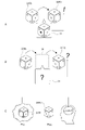
- FIG. 3 is a schematic diagram for explaining change blindness.
- FIG. 3A schematically shows how the visual object 2 changes while the user 1 is gazing at the visual object 2.
- the image of the dice 30 is changed as the visual object 2.
- the dice 30 are drawn so that the left side surface on the left side, the right side surface on the right side, and the upper surface connected to the left and right side surfaces can be seen in the drawing.
- two points are drawn on the left side surface and three points are drawn on the right side surface.
- three points are drawn on the left side surface and two points are drawn on the right side surface, and the positional relationship is opposite to that before the change.
- the image of the dice 30 is switched while the user 1 is gazing at the image of the dice 30.
- the user 1 will visually recognize the change that a new point is added between the two points on the left side surface. Further, the user 1 visually recognizes a change in which the central point of the three points disappears on the right side surface. The state in which points are added or disappear from each surface is perceived as a visual transient.
- FIG. 3B schematically illustrates how the visual object 2 is changed so that the visual change blindness occurs for the user 1.
- the points drawn on the side surface of the dice 30 change, as in FIG. 3A.
- the image of the dice 30 before the change is displayed.
- the blank image 32 on which the dice 30 are not drawn is displayed for a certain period of time.
- an image of the changed dice 30 in which the number of points on the left side surface and the right side surface is changed is drawn.
- the user 1 does not perceive the visual transition state as shown in FIG. 3A.
- the visual change information 31 does not occur.
- FIG. 3C is a schematic diagram for explaining the cognitive process of the user 1 with respect to the change of the visual object 2.
- recognizing a change in the visual object 2 means, for example, recognizing the visual object 2 before and after the change, and comparing the recognized results with the user to change the visual object 2. 1 means to notice. This is different from perceiving a change in an image (visual motion perception), for example, by visually observing the addition or disappearance of points on the dice 30 (visual transition state).
- the visual object 2 before the change is recognized by the user 1, and various information about the visual object 2 is generated in the brain of the user 1.
- the information generated at this time includes a visual short-term memory (Visual Short Term Memory) that is an image of the visual object 2, a semantic memory that associates the visual object 2 with the knowledge of the user 1, and a visual object 2.
- Visual Short Term Memory Visual Short Term Memory
- semantic memory that associates the visual object 2 with the knowledge of the user 1
- Information such as visual impression (Impression) and attractiveness (Saliency) indicating the degree of conspicuity of the visual object 2 can be mentioned.
- the visual object 2 before the change is switched to the blank image 32, and the visual object 2 after the change is displayed after a certain period of time.
- the user 1 changes the currently displayed visual object 2 after the change to the visual object 2 before the change based on the information such as the short-term memory generated when the user 1 recognizes the visual object 2 before the change. It will be judged whether they are the same or not. Therefore, the user 1 notices the change of the visual object 2 only when he / she can recognize a remarkable difference in the cognitive comparison with the visual impression or memory. This is a factor that causes visual change blindness.
- the visual impression and the higher-order visual are not the information at the pixel value level constituting the visual information.
- the visual cognitive space is, for example, a space used when comparing objects visually recognized by humans.
- the cognitive space the smaller the distance between the objects to be compared, the more similar the objects are judged to be. Conversely, the greater the distance between the objects, the less similar the objects are.
- the distance in the visual cognitive space is referred to as the cognitive distance.
- the cognitive distance can be expressed, for example, as the degree to which humans can perceive the difference between the objects to be compared.
- a latent cognitive scale in which the cognitive distance is defined by using the distance in the latent space is used as a scale for quantitatively handling the cognitive distance (the degree of recognition of visual changes). The characteristics of the latent space will be described below.
- FIG. 4 is a schematic diagram showing an example of a latent space relating to a visual object.
- the latent space 40 is a space that represents the visual object 2 using latent variables.
- FIG. 4 schematically illustrates the latent space 40 as a set of points corresponding to the visual object 2.
- the latent space 40 is typically configured by performing machine learning using a dataset of a large number of visual objects 2.
- the data set used here is, for example, a set of data of visual objects having the same motif (for example, an image of a person, an image of an animal, an image of a plant, an image of a landscape, an image of food, etc.).
- machine learning is used to extract latent variables for each of the visual objects 2 in the dataset.
- the latent space 40 is constructed based on the latent variables extracted in this way.
- a point in the latent space 40 by specifying the values of a plurality of latent variables.
- a point (a set of values of a plurality of latent variables) in the latent space 40 represents one visual object 2. The closer the two visual objects 2 are in the latent space 40, the more similar the visual objects 2 are.
- the point (position in the latent space 40) in the latent space 40 is calculated.
- the visual object 2 that is not in the data set such as the input object 3 and the reference object 5 (see FIG. 1), can be arranged in the latent space 40.
- the morphing process for changing the input object 3 becomes possible.
- data regarding at least one change object 4 is calculated.
- the object processing unit 27 shown in FIG. 2 executes the morphing process and calculates the data related to the change object 4.
- FIG. 4 shows four change objects 4 in which the input object 3 is changed so as to approach the reference object 5.
- the points corresponding to the input object 3 are described as Ps
- the points corresponding to the reference object 5 are described as Pf
- the points corresponding to the four change objects 4 are described as P1 to P4.
- the direction from the input object 3 (Ps) to the reference object 5 (Pf) is the change direction 41 that changes the input object 3.
- the points P1 to P4 are set in this order on a straight line between the points Ps and Pf. That is, the change object 4 represented by the point P1 is closest to the input object 3, and the change object 4 represented by the point P4 is closest to the reference object 5.
- the change direction 41 is appropriately set based on the information indicating the change direction 41 in the latent space 40. Then, data regarding at least one change object in which the input object 3 is changed along the change direction 41 in the latent space 40 is output. This makes it possible to change the input object 3 in a desired direction.
- the change direction 41 may be a direction approaching the reference object 5 as described above, or may be a direction set by the user 1. Further, the default change direction 41 or the like may be set.
- the change object 4 is switched and displayed in a predetermined order instead of the input object 3.
- This order is typically the order in which the distance between the input object 3 and the change object 4 in the latent space 40 is short. That is, the changing objects 4 are displayed in the order similar to the input objects 3. For example, in the example shown in FIG. 4, the change objects 4 represented by the points P1 to P4 are displayed in this order. As a result, for example, the input object 3 can be changed stepwise toward the target reference object 5.
- the object processing unit 27 calculates the data related to the change object 4 by setting the amount of change (distance in the latent space) and the number of changes in the change direction 41 in the latent space 40.
- the amount of change and the number of changes are set based on the latent cognitive scale. In the following, a method for generating a latent cognitive scale will be specifically described.
- FIG. 5 is a schematic diagram for explaining a method of generating a latent cognitive scale.
- the latent cognitive scale conducts a cognitive experiment in which a human judges whether or not the images of the two visual objects 2 are the same at the cognitive level, and associates the judgment result with the distance between the two visual objects 2 in the latent space. It is generated by. It can be said that this cognitive experiment is an experiment for examining the human cognitive distance between two visual objects 2.
- the visual object 2 represented by two different points in the latent space 40 is displayed to the human examiner in a state in which the visual change information 31 as shown in FIG. 3A does not occur. Then, the tester's cognitive detection rate for the change of the visual object 2 is measured.
- FIGS. 5A and 5B show an example of a test screen 34 used in a cognitive experiment.
- four visual objects 2 (visual objects 2 numbered 1 to 4) arranged in a 2 ⁇ 2 grid pattern are displayed.
- an image of a person's face is used as the visual object 2. Therefore, the cognitive experiments shown in FIGS. 5A and 5B are experiments for generating a latent cognitive scale for a human face.
- test screen 34 before the change (test screen 34 on the left side of the figure) is first displayed.
- the entire test screen 34 before the change is switched to the blank image 32.
- the blank image 32 is displayed for a certain period of time (for example, 100 ms).
- the blank image 32 is switched to the changed test screen 34.
- This is a display method that causes the user 1 to visually change blindness in response to the change on the test screen 34. This makes it possible to present changes in the image without generating visual change information 31.
- test object 6 the visual object 2 that changes before and after the display of the blank image 32
- test objects 6a and 6b the test objects 6 before and after the change
- the other three visual objects 2 are dummy objects 7 that do not change before and after the blank image 32.
- the visual object 2 (third visual object 2) arranged at the lower left of the test screen 34 is the test object 6.
- the test object 6a corresponds to the first visual object
- the test object 6b corresponds to the second visual object 2.
- the distance between the test objects 6a and 6b in the latent space 40 is relatively small. Therefore, the test objects 6a and 6b may be perceived as similar images. In this case, the change of the test object 6 may not be detected.
- the distance between the test objects 6a and 6b in the latent space 40 is relatively large. Therefore, the test objects 6a and 6b are likely to be recognized as separate images from each other. In this case, it is considered that there is a high possibility that a change in the test object 6 will be detected.
- this cognitive experiment is a test in which the examiner determines whether or not there is a cognitive difference between the test objects 6a and 6b.
- Such cognitive experiments are conducted on a plurality of testers. As a result, for each change direction 41 in the latent space 40, a human cognitive detection rate (correct answer rate for determination work) for a visual change according to a distance in the change direction 41 is calculated.
- the cognitive detection rate for the visual change of the test object 6 is simply referred to as the change detection rate.
- the change detection rate represents the degree of recognition for visual changes and corresponds to the distance (cognitive distance) in the visual cognitive space. For example, if the change detection rate is high, the cognitive distance is large, and if the change detection rate is low, the cognitive distance is small.
- the latent cognitive scale is generated by modeling the correspondence between the change detection rate calculated in this way and the distances of the test objects 6a and 6b in the latent space 40. For modeling, for example, an approximate curve that approximates experimental data, numerical interpolation that interpolates experimental data, or the like may be appropriately used.
- the method for generating the latent cognitive scale 45 is not limited to the method described with reference to FIG. 5, and various methods may be used.
- a cognitive experiment may be performed in which the test object 6b and the test object 6c are displayed at the same time as the test object 6a, and the examiner is made to judge an object close to the test object 6a. It can be said that this is an experiment that directly determines the degree of cognitive difference.
- the test objects 6b and 6c are, for example, objects in which the test objects 6a are changed in the same change direction 41 by different amounts of change. Of these, the test object 6b is set to an object closer to the test object 6a than the test object 6c. That is, the test object 6b is the answer object, and the test object 6c is the object for comparison.
- this cognitive experiment is a test in which the examiner determines the degree of cognitive difference between the test objects 6a and 6b.
- the method for generating the latent cognitive scale 45 includes the following procedure. First, data for each of the test object 6a and the test object 6b represented by different points in the latent space 40 for the visual object 2 is generated. Next, a cognitive experiment is performed that causes the examiner to determine the presence or absence of a cognitive difference between the test objects 6a and 6b. Alternatively, a cognitive experiment is performed that causes the examiner to determine the degree of cognitive difference between the test objects 6a and 6b. Next, data in which the determination result of the cognitive experiment and the distance of the points representing the test objects 6a and 6b in the latent space 40 are associated with each other are acquired. Then, based on the acquired data, a latent cognitive scale 45 showing the relationship between the distance in the latent space 40 and the degree of recognition of the change of the visual object 2 according to the distance is generated.
- FIG. 6 is a schematic diagram showing an example of a graph constituting the latent cognitive scale.
- FIG. 6 illustrates a schematic graph constituting the latent cognitive scale 45.
- the horizontal axis of the graph is the distance in the Latent Space
- the vertical axis is the detection rate for the visual change of the test object 6.
- a graph of the distance and the change detection rate in the latent space 40 will be referred to as a scale graph 46.
- the scale graph 46 is graph data showing the degree of recognition of the change of the visual object 2 according to the distance in the latent space 40.
- the data format of the scale graph 46 is not limited.
- the scale graph 46 may be recorded, for example, as a set of data points constituting the graph. Further, for example, when the shape of the graph is represented by a model such as an approximate curve, the combination of variables of the model is recorded as the scale graph 46. Alternatively, both data points and variable combinations may be recorded.
- the scale graph 46 shown in FIG. 6 is a plot of the change detection rate for one change direction 41 starting from the point P0 in the latent space 40.
- the point Q0 which is the starting point of the scale graph 46, corresponds to, for example, the test object 6a before the change shown in FIG.
- the scale graph 46 has a section (for example, a section between points Q2 and Q3) in which the change detection rate increases sharply. In this section, for example, it is considered that the cognitive difference with respect to the visual object 2 corresponding to the point Q0 becomes large. In this way, it is conceivable that the change detection rate changes non-linearly with respect to the distance in the latent space 40.
- FIG. 7 is a schematic diagram showing an example of scale graphs having different change directions 41.
- the latent cognitive scale 45 when the latent cognitive scale 45 is generated, a plurality of change directions 41 are set, and a scale graph 46 for each change direction 41 is calculated. Therefore, the latent cognitive scale 45 has a plurality of graph data (scale graph 46) showing the degree of recognition of the change of the visual object 2 according to the distance in the latent space 40 in each of the different directions 41 in the latent space 40. Is included.
- FIG. 7 schematically shows a change direction 41 in the latent space 40 and a scale graph 46 corresponding to each change direction 41.
- the state of change of the change object 4 differs depending on the change direction 41.
- the latent space 40 composed of an image of a person, as shown in FIG. 7, there are a change direction 41 in which the age changes, a change direction 41 in which the gender changes, and the like.
- FIG. 8 is a schematic diagram showing an example of the change direction 41 in the latent space 40.
- FIG. 8 schematically illustrates a region 42a including a male face and a region 42b including a female face in the latent space 40.
- the image of a man changes to an image of a woman
- the image of a woman changes to an image of a man. become.
- the change direction 41 that changes the visual object 2 beyond the boundary between the area 42a and the area 42b is the direction that changes the gender of the person.
- a change direction 41 in which the age increases (decreases) a change direction 41 in which the degree of opening of the eyes changes, a change direction 41 in which the hair length and color change, or a change direction 41 in which these are combined.
- the change direction 41 can be said to be an axis for changing various higher-order semantic characteristics of visual information.
- the characteristics of the latent cognitive scale 45 differ depending on such semantic characteristics. That is, the shape of the scale graph 46 is different for each change direction 41.
- the latent space 40 used to generate the latent cognitive scale 45 it is possible to use a feature amount space composed of at least one feature amount related to the visual object 2.
- the feature space is, for example, a high-dimensional vector space in which various features are set as latent variables. That is, it can be said that the feature space is a latent space 40 in which the semantic characteristics of each latent variable are clearly shown. It should be noted that the feature space may be configured using only a single feature. This is one-dimensional data in which the visual objects 2 are arranged according to one feature.
- the change direction 41 is set in a direction along a feature amount indicating the appearance characteristics of the person.
- the feature amount indicating the appearance characteristic of the person include the feature amount indicating gender, age, eye opening degree, hair length, and the like.
- the latent cognitive scale 45 is configured to have characteristics suitable for the assumed user 1.
- the cognitive distance may differ depending on the characteristics of the user 1 such as gender and age. For this reason, for example, by conducting cognitive experiments targeting male (or female) testers and cognitive experiments targeting testers classified by age group, latent cognition according to the user's profile can be performed.
- the scale 45 scale graph 46
- the plurality of scale graphs 46 constituting the latent cognitive scale 45 may include data generated for each human characteristic. In this case, data matching the characteristics of user 1 is selected from a plurality of scale graphs 46 and used. This makes it possible to appropriately generate the visual content 10 that matches the assumed user 1.
- the latent cognitive scale 45 is a model in which the distance in the latent space 40 can be used as the human cognitive distance (change detection rate) by associating the latent space 40 with the human change cognitive characteristics. ..
- the latent cognitive scale 45 it is possible to calculate a design guideline for how much change should be set when the visual object 2 is changed unknowingly.
- the latent cognitive scale 45 (scale graph 46)
- a distance calculation function that takes two visual objects 2 as inputs and outputs the cognitive distance of each visual object 2.
- the change direction 41 connecting the two visual objects 2 is calculated.
- the scale graph 46 corresponding to the change direction 41 is selected, and the position of each visual object 2 on the selected scale graph 46 is calculated.
- the difference in the change detection rate at the position of each visual object 2 is output as the cognitive distance between the visual objects 2.
- such a distance calculation function is implemented in the object processing unit 27 described with reference to FIG.
- An example of applying the distance calculation function is a tool for setting the amount of change when the visual object 2 is changed.
- this tool for example, in a section where the cognitive distance (change detection rate) changes sharply, the amount of change in the visual object 2 is set to a small value. This makes it possible to suppress the recognition of visual changes.
- a tool or the like that divides the change of the visual object 2 into a plurality of times may be realized according to the linear / non-linear characteristics of the scale graph 46. In this case, it is possible to probabilistically estimate the risk of change detection by dividing the change into a plurality of times.
- the processing using the latent cognitive scale 45 will be specifically described.
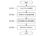
- FIG. 9 is a flowchart showing an example of the change object output process.
- FIG. 10 is a schematic diagram for explaining the change object output process.
- a change object output process for outputting data relating to at least one change object 4 in which the input object 3 is changed is executed based on the latent cognitive scale 45.
- the input object 3 is first acquired by the data acquisition unit 26 (step 101).
- the data of the visual object 2 which is the input object 3 is appropriately read from the storage unit 24, another device, or the like.
- the data acquisition unit 26 reads an instruction value regarding the degree of recognition of the change of the visual object 2 (step 102).
- the instruction value input by the user 1 and the instruction value stored in the storage unit 24 are appropriately read.
- the indicated value of the degree of recognition is the threshold value ⁇ of the degree of recognition.
- the threshold value ⁇ is expressed as, for example, a threshold value of the change detection rate for a visual change caused by switching and displaying the change object 4. Further, in step 102, information indicating the change direction 41 that changes the visual object 2 is read.
- the object processing unit 27 executes a calculation (optimization calculation) for optimizing the cognitive distance and the amount of change (step 103).
- the amount of change is the amount of change in visual change caused by switching and displaying the change object 4. This is the amount of change between each change object 4 and the object displayed immediately before each change object 4 (input object 3 or change object 4 displayed immediately before).
- the optimization calculation will be described with reference to FIG.
- the position (Ps) of the input object 3 in the latent space 40 is calculated. Further, the scale graph 46 corresponding to the change direction 41 of the input object 3 is selected. Then, based on the selected scale graph 46, the amount of change to be set in each change object 4 is set according to the threshold value ⁇ of the degree of recognition (change detection rate).
- the change detection rate at the position Ps of the input object 3 is Ds.
- the position P1 of the change object 4 displayed next to the input object 3 is set within the range where the change detection rate is smaller than the value (Ds + ⁇ ) obtained by adding ⁇ to the change detection rate Ds of the input object 3.
- the object. This sets the distance (P1-Ps) that is the amount of change of the change object 4 of P1.
- the position P2 of the change object 4 displayed next to the change object 4 of P1 is set.
- the position P2 is set in a range where the change detection rate is smaller than the value (D1 + ⁇ ) obtained by adding ⁇ to the change detection rate D1 at the position P1.
- the points after P2 are calculated in the same manner.
- the change object 4 is switched and displayed so that the degree of recognition for the visual change caused by switching and displaying the change object 4 does not exceed the threshold value ⁇ of the recognition degree.
- the distance in the latent space 40 corresponding to the amount of change in the visual change is set. This makes it possible to suppress the risk that the user 1 detects a visual change that occurs each time the change object 4 is switched to a threshold value or less.
- data relating to the change object 4 is output using the processing result of the optimization process (step 104). For example, data related to the change object 4 corresponding to each point is output from the latent variables at the positions P1, P2, ... Of the change object 4. For example, when the number of times the input object 3 is changed is set, the data related to the change object 4 for that number of times is calculated.
- the reference object 5 to be the final change target when the reference object 5 to be the final change target is set, at least one change object 4 in which the input object 3 is changed so as to approach the reference object 5 corresponding to the input object 3 in the latent space 40. Data is output (see Fig. 4 etc.). This makes it possible to switch the input object 3 to the reference object 5 and display it without the user 1 noticing it.
- FIG. 11 is a flowchart showing an example of cognitive parameter output processing.
- FIG. 12 is a schematic diagram for explaining the cognitive parameter output process.
- the cognitive parameter output process for outputting the cognitive parameter C indicating the degree of cognition for the change from the input object 3 to the reference object 5 is executed based on the latent cognitive scale 45.
- the change detection rate for the overall visual change caused by changing the input object 3 to the reference object 5 is output.
- the change detection rate for the overall visual change is the change detection rate for the visual change that occurs until the reference object 5 is displayed in the process of changing the input object 3 to the reference object 5.
- the overall change detection rate differs between the case where the input object 3 directly changes to the reference object 5 and the case where the input object 3 gradually changes to the reference object 5 via the change object 4.
- the change detection rate in the entire change process is output as the cognitive parameter C.
- the cognitive parameter output process the input object 3 and the reference object 5 are first acquired by the data acquisition unit 26 (steps 201 and 202).
- the data of the visual object 2 which is the input object 3 and the reference object 5 is appropriately read from the storage unit 24, another device, or the like.
- the object processing unit 27 executes a process (cognitive distance calculation) for calculating the cognitive distance between the input object 3 and the reference object 5 (step 203).
- the cognitive distance calculation will be described with reference to FIG.
- the cognitive distance calculation first, the position (Ps) of the input object 3 and the position (Pf) of the reference object 5 in the latent space 40 are calculated. Further, the scale graph 46 corresponding to the change direction 41 of the input object 3, that is, the direction from Ps to Pf is selected. Then, the cognitive distance between the input object 3 and the reference object 5 is calculated based on the selected scale graph 46.
- the difference between the change detection rates Ds and Df of the input object 3 and the reference object 5 in the scale graph 46 is calculated as the cognitive distance. That is, the difference (Df—Ds) between the change detection rate Df of the reference object 5 and the change detection rate Ds of the input object 3 is calculated. This is the change detection rate when the input object 3 is directly changed to the reference object 5, and corresponds to the cognitive distance between the input object 3 and the reference object 5.
- the cognitive parameter C regarding the degree of cognition is output using the processing result of the cognitive distance calculation (step 204).
- the cognitive parameter C the first change detection rate in the first change processing in which the input object 3 is directly changed to the reference object 5 is output.
- the object processing unit 27 outputs the first change detection rate for the visual change accompanying the first change processing that changes the input object 3 to the reference object 5 at once. This makes it possible to estimate the rate at which the user 1 notices the change when the input object 3 is directly changed to the reference object 5. Further, the first change detection rate output as the cognitive parameter C can also be used as a parameter representing the cognitive distance between the input object 3 and the reference object 5.
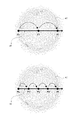
- FIG. 13 is a schematic diagram showing another example of the cognitive parameter output process.
- a method of calculating the cognitive parameter C will be described assuming a change process (hereinafter referred to as a second change process) in which the input object 3 is changed to the reference object 5 in a plurality of times.
- the second change processing includes a plurality of division change processing in which the input object 3 is changed into the reference object 5 in a plurality of times.
- FIG. 13A the input object 3 is changed to the reference object 5 by the two division change processes via the change object 4 corresponding to the point P1.
- FIG. 13B the input object 3 is changed to the reference object 5 by the four division change processing via the three change objects 4 corresponding to the points P1'to P3'.
- the second change detection rate for the visual change accompanying the second change processing is output as the cognitive parameter C. Therefore, the second change detection rate is the rate at which a visual change is detected by the time the plurality of divisional change processes are completed and the reference object 5 is finally displayed.
- the second change detection rate can be expressed as the product of the division change detection rates, which are the change detection rates in the plurality of division change processes. Therefore, when outputting the second change detection rate, the division change detection rate for each division change processing is first calculated. Specifically, in each division change process, the difference between the value of the scale graph 46 at the position of the object after the change and the value of the scale graph 46 at the position of the object before the change is calculated. The difference between the values of the scale graph before and after this change is the division change detection rate for each division change processing. This division change detection rate is
- the second change detection rate is calculated by integrating the division change detection rates for each division change processing.
- the second change detection rate is calculated by multiplying the division change detection rate for the visual change accompanying each of the plurality of division change processes.
- the product of the first divided change detection rate and the second divided change detection rate is the total change detection rate (second change detection rate).
- the product of the first to fourth division change detection rates is the second change detection rate.
- the second change detection rate calculated in this way is used as the cognitive parameter C.
- the concealment success rate may be directly calculated as the cognitive parameter C.
- the concealment success rate is configured as a function that is inversely proportional to, for example, the change detection rate.
- the rate at which one visual change is noticed is lower than, for example, as compared with the first change processing. ..
- the number of visual changes occurs increases, so if the number of changes is too large. There is also the possibility that visual changes will be noticed.
- the overall detection rate (second change detection rate) in each process is output for the second change process in which the number of changes and the amount of change are set to different values. Then, by comparing the output results, a second change process is designed that can sufficiently conceal the visual change as a whole (for example, the second change detection rate is equal to or less than the threshold value). (See FIG. 13).
- FIG. 14 is a schematic diagram showing an example of content generated by using an authoring tool to which the content generation system 100 is applied.
- the authoring tool is an application for designing and editing visual content 10 including a visual object 2 such as an image.
- the visual content 10 shown in FIG. 14 is generated by using an authoring tool to which the content generation system 100 is applied, and is designed so that the displayed content changes without being noticed by the user 1.
- the visual content 10 an article composed of photographs and characters will be described as an example.
- the figure on the left side of FIG. 14 is the visual content 10 before the display content is changed. Further, the figure on the right side of FIG. 14 is the visual content 10 after the display content is completely changed.
- the content (photograph and text) of the article is completely different between the visual content 10 before the change and the visual content 10 after the change.
- a second change process is executed in which the content of each article is changed stepwise at the timing when the visual change blindness occurs for the user 1. Specifically, a state in which the user 1 has his eyes closed is detected, and the content of each article is gradually switched at that timing.
- the number of times each visual object 2 included in the article is changed is set individually. Therefore, for example, the landscape image, the person image, and the food image, which are the visual objects 2 in the article, are switched by the number of changes set for each image, and the images displaying different landscapes, people, and foods are displayed. Will be updated to.
- the number of changes and the amount of change of each visual object 2 are set on the design screen of the authoring tool.
- FIG. 15 is a schematic diagram showing an example of the design screen of the authoring tool.
- FIG. 15 illustrates a design screen 50 used when designing the visual content 10 shown in FIG.
- the design screen 50 is provided with content input areas 51a and 51b, a threshold value setting field 52, and an analysis result display area 53.
- the content input areas 51a and 51b are areas for inputting the visual content 10 before and after the change.
- the visual content 10 before and after the change input by the user 1 is displayed.
- each visual object 2 included in the visual content 10 input to the content input area 51a is an input object 3.
- the visual object 2 included in the visual content 10 input to the content input area 51b is a reference object 5 corresponding to each input object 3.
- the reference object 5 is an object input by the user 1.
- the landscape image, the person image, and the food image included in the visual content 10 before the change are described as the input image 13a, the input image 13b, and the input image 13c, respectively.
- the input images 13a to 13c are input objects 3.
- the landscape image, the person image, and the food image included in the changed visual content 10 are referred to as a reference image 15a, a reference image 15b, and a reference image 15c, respectively.
- Reference images 15a to 15c are reference objects 5.
- the threshold value setting field 52 is a field for inputting a threshold value for the second change process for changing the visual content 10 in a plurality of times.
- a threshold value of the second change detection rate for the visual change accompanying the second change process is set.
- This threshold value is a threshold value of the change detection rate until the reference object 5 is finally displayed when each input object 3 is gradually changed to the corresponding reference object 5.
- an indicator for setting a threshold value is displayed as a threshold value setting field 52.
- a threshold value setting field 52 for directly inputting a numerical value of the threshold value may be provided.
- the analysis result display area 53 is an area in which the analysis result for each visual object 2 by the authoring tool is displayed.
- a landscape image input image 13a and a reference image 15a
- a person image input image 13b and a reference image 15b
- a cooking image input image 13c and reference
- the analysis results for the image 15c) are displayed respectively. This allows the user 1 to design the visual content 10 while checking the analysis result.
- the analysis result includes the first change detection rate associated with the first change process that changes the input object 3 to the reference object 5 at once. This is the change detection rate when the input object 3 is directly changed to the reference object 5, and is calculated by the method described with reference to FIG. 12, for example.
- the first change detection rate is displayed as the current change detection rate (Current Risk of Detection).
- the analysis result includes the number of processing times (number of changes) of the second change processing that changes the input object 3 into the reference object 5 in a plurality of times.
- the authoring tool executes an optimization process related to the second change process.
- the optimum number of processes is calculated by this optimization process.
- the number of processes is displayed as the optimum number of change steps (Preferable Number of change steps).
- the analysis result also includes the second change detection rate for the visual change accompanying the second change processing.
- This is the change detection rate when the input object 3 is changed to the reference object 5 in a plurality of times by the optimized second change process.
- the second change detection rate is calculated by the method described with reference to, for example, FIG. 13 and the like.
- the second change detection rate is displayed as the expected change detection rate (Expected Risk of Detection).
- the analysis result includes the amount of change calculated by the optimization process related to the second change process. This is the amount of change in each of the plurality of divided change processes executed as the second change process, and is the distance in the latent space for calculating the data regarding the change object 4.
- the change amount information is not presented on the setting screen 60, but is used when calculating the data related to the change object 4.
- the data acquisition unit 26 acquires the threshold value of the second change detection rate input in the threshold value setting field 52. Then, the object processing unit 27 sets the number of times of the plurality of divisional change processing and the amount of change in each of the plurality of divisional change processing so that the second change detection rate is equal to or less than the threshold value of the second change detection rate. ..
- Second change processing is calculated.
- the second change detection rate at this time is determined by the threshold value. Such processing is repeated until the second change detection rate becomes equal to or less than the threshold value. This makes it possible to calculate a process in which the change detection rate in the entire second change process is equal to or less than the threshold value while minimizing the number of changes. This makes it possible to realize the visual content 10 that changes without being noticed by the user 1 with a small number of changes.
- the data related to the change object 4 is calculated using the amount of change and the number of changes calculated in the optimization process.
- the calculated data related to the change object 4 is stored as data of the visual content 10, for example, and is used when displaying the visual content 10.
- FIG. 16 is a schematic diagram showing an example of using a video communication tool to which the content generation system 100 is applied.
- the video communication tool is a communication tool used for, for example, an online meeting.
- the user 1 can transmit a video of the user 1 himself / herself to another user (communication partner) at a remote location.
- the image captured by the user 1 is corrected, and the corrected image is transmitted to the communication partner.
- This tool corrects cosmetic characteristics such as complexion, age, hairstyle and makeup.
- the content of the correction is not limited and can be set as appropriate.
- the timing for switching the corrected image is the timing at which a visual change blindness or the like occurs in the communication partner viewing the corrected image.
- the video communication tool has a guide function when setting such an appearance correction.
- the guide function the user 1 can obtain a guideline for making corrections to his / her face information (video) in online communication.
- a cognitive parameter is presented as a guideline for changing the image so that the change due to the correction is not recognized by the communication partner.
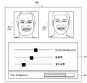
- FIG. 17 is a schematic diagram showing an example of a setting screen for correcting face information.
- FIG. 17 shows an example of the setting screen 60 for correcting the image (face information) of the face of the user 1.
- the process for correcting face information is provided on the setting screen 60 with an original image display area 61, a corrected image display area 62, a parameter setting field 63, and a detection risk display area 64.
- the original image display area 61 is an area in which the original image 16 captured from the image taken by the user 1, for example, is displayed.
- the original image 16 is an uncorrected image and is an image showing the current state of the user 1.
- the original image 16 in which the face of the user 1 is photographed becomes the input object 3.
- the corrected image display area 62 is an area in which the corrected image 17 corrected from the original image 16 is displayed.
- the corrected image 17 is an image obtained by correcting the original image 16 based on the change direction and the amount of change set as the correction parameters described later.
- the corrected image 17 is calculated by a morphing process that changes the original image 16 in the latent space 40.
- the corrected image 17 in which the face of the user 1 is corrected becomes the reference object 5 corresponding to the original image 16 which is the input object 3.
- the reference object 5 is an object in which the input object is changed according to the change direction and the change amount input by the user 1.
- the parameter setting field 63 is a field for setting various parameters related to the correction of the original image 16.
- a correction parameter Good looking value
- a concealment rate and the number of changes are set.
- the user 1 can set each parameter by moving the slider provided in the parameter setting field 63.
- the correction parameter is a parameter that specifies the change direction 41 (correction direction) that changes the original image 16 and the change amount (correction amount).
- the change direction 41 that changes the original image 16 is set in a direction such that the contour of the face becomes thinner or the age becomes younger, for example, in the latent space 40.
- the value indicated by the slider is the amount of change in the original image 16.
- the change direction 41 may be set by combining a plurality of feature quantities.
- the instruction information regarding the change direction 41 is information that indicates the change direction 41 by at least one of the feature quantities.
- the concealment rate is a parameter indicating the degree of concealment of changes that occur when switching images in the correction of the original image 16. That is, it can be said that the concealment rate represents the degree to which the visual change accompanying the switching of images is not noticed. For example, the larger the visual change, the smaller the concealment rate, and the smaller the visual change, the larger the concealment rate. This has the opposite relationship to the change detection rate.
- the number of changes is the number of display switchings performed until the original image 16 is corrected to the corrected image 17. For example, when the number of changes is one, the first change process of changing the original image 16 into the corrected image 17 at a time is executed. When the number of changes is a plurality of times, the second change process of changing the original image 16 into the corrected image 17 by dividing the original image 16 into a plurality of times is executed.
- the detection risk display area 64 is an area for displaying the detection risk in which the correction is detected when the original image 16 is changed to the corrected image 17 by using the value set in the parameter setting field 63.
- the detection risk is represented by, for example, the overall change detection rate until the corrected image 17, which is the reference object 5, is displayed.
- the detection risk is calculated by the object processing unit 27.
- the correction process is the first change process.
- the first change detection rate is calculated as the detection risk (see FIG. 12 and the like).
- the correction process is a second change process that changes stepwise via the change object.
- the second change processing according to the concealment rate and the number of changes is appropriately set, and the second change detection rate is calculated as the detection risk (see FIG. 13 and the like).
- the calculated detection risk is displayed in the detection risk display area 64.
- the detection risk By displaying the detection risk in this way, it is possible to convey to the user 1 information such as whether or not the content of the set correction is easily noticed by the communication partner.
- the user can set a correction with a lower detection risk by taking measures such as suppressing the amount of change or increasing the number of changes. If the user 1 confirms and understands the detection risk, the correction process for correcting the image taken by the user 1 with the content set in the parameter setting field 63 is executed, and the gradually corrected image is the communication partner. Will be sent as appropriate.
- data or cognitive parameters related to the change object 4 are output using the latent cognitive scale 45 in which the degree of recognition of the change of the visual object 2 is associated with the distance in the latent space 40. ..
- the change object 4 is an object in which the input object 3 is changed according to the instruction information of the degree of recognition.
- the cognitive parameter is a value representing the degree of recognition of the change from the input object 3 to the reference object 5.
- a human face image is mainly used as a visual object.
- This technique can be applied not only to facial images but also to graphics such as images of general objects, CG (Computer Graphics), and logo marks.
- CG Computer Graphics
- logo marks logo marks.
- a latent space related to the visual object to which the processing target belongs is constructed, and a latent cognitive scale in the latent space is constructed. This makes it possible to generate change objects that are difficult to notice changes for various visual objects, and to present parameters that represent cognitive distance.
- an application tool (authoring tool or video communication tool) that mainly involves a process of outputting data related to a change object
- an application tool or the like that does not output data related to the change object may be configured.
- a tool or the like that outputs the cognitive distance between two images may be configured based on the latent cognitive scale.
- the information processing method according to the present technology is executed by the computer of the content generation system operated by the user.
- the information processing method and the program according to the present technology may be executed by a computer mounted on the content generation system and another computer capable of communicating via a network or the like.
- the information processing method and program according to the present technology can be executed not only in a computer system composed of a single computer but also in a computer system in which a plurality of computers operate in conjunction with each other.
- the system means a set of a plurality of components (devices, modules (parts), etc.), and it does not matter whether or not all the components are in the same housing. Therefore, a plurality of devices housed in separate housings and connected via a network, and one device in which a plurality of modules are housed in one housing are both systems.
- the information processing method and program execution related to this technology by a computer system are different when, for example, the process of acquiring an input object and the process of calculating a change object or a cognitive parameter are executed by a single computer, and each process is different. Includes both when run by a computer. Further, the execution of each process by a predetermined computer includes having another computer execute a part or all of the process and acquiring the result.
- the information processing method and program related to this technology can be applied to the configuration of cloud computing in which one function is shared by a plurality of devices via a network and processed jointly.
- the present technology can also adopt the following configurations.
- An acquisition unit that acquires data related to an input object that is a visual object, In the latent space according to the instruction information including the instruction value regarding the recognition degree, based on the model showing the relationship between the distance in the latent space regarding the visual object and the recognition degree with respect to the change of the visual object according to the distance.
- An output unit that outputs data on at least one change object that has changed the input object, or at least one of the cognitive parameters representing the degree of recognition of the change from the input object to the reference object corresponding to the input object.
- Information processing device to be equipped.
- the indicated value is a threshold value of the degree of recognition
- the at least one change object is an object that is switched and displayed in a predetermined order in place of the input object.
- the output unit is visually generated by switching and displaying the change object so that the recognition degree for the visual change caused by switching and displaying the change object does not exceed the threshold value of the recognition degree.
- An information processing device that sets a distance in the latent space corresponding to the amount of change.
- the output unit maximizes the distance in the latent space corresponding to the amount of change within the range in which the degree of recognition for the visual change caused by switching and displaying the change object does not exceed the threshold value of the degree of recognition.
- Information processing device to set to the value.
- (4) The information processing apparatus according to (2) or (3).
- the predetermined order is an information processing apparatus in which the distance between the input object and the change object in the latent space is short.
- the output unit is an information processing device that calculates data regarding at least one change object in which the input object is changed so as to approach a reference object corresponding to the input object in the latent space.
- the instruction information includes information indicating a change direction in the latent space that changes the input object.
- the output unit is an information processing device that calculates data regarding at least one change object in which the input object is changed along the change direction in the latent space. (7) The information processing apparatus according to (6).
- the latent space is a feature space composed of at least one feature related to the visual object.
- the instruction information is information processing device that indicates the change direction by at least one of the feature quantities.
- the information processing apparatus according to any one of (2) to (7), and further.
- the display device is controlled so as to display the target object to be displayed among the input object and at least one change object, and a state that causes a visual change blindness to the user who sees the target object is detected.
- An information processing device including a display control unit that controls the display device so as to change the target object to the next change object to be displayed in accordance with the timing at which the visual change blindness occurs.
- the information processing apparatus according to (8).
- the state of causing the visual change blindness is at least one of a state in which the user closes his eyes, a state in which the display of the target object is obstructed, and a state in which the display parameters of the target object are changed.
- Information processing equipment including. (10) The information processing apparatus according to any one of (1) to (9).
- the output unit is an information processing device that outputs, as the cognitive parameter, a change detection rate for an overall visual change caused by changing the input object to the reference object.
- the output unit is an information processing device that outputs a first change detection rate for a visual change accompanying a first change process that changes the input object into the reference object at once.
- (12) The information processing apparatus according to (10) or (11).
- the information processing unit outputs a second change detection rate for a visual change associated with the second change process, which includes a plurality of divided change processes for changing the input object to the reference object in a plurality of times.
- Device (13) The information processing apparatus according to (12).
- the output unit is an information processing device that calculates the second change detection rate by multiplying the division change detection rate for the visual change associated with each of the plurality of division change processes.
- the information processing apparatus according to any one of (12) and (13).
- the acquisition unit acquires the threshold value of the second change detection rate, and obtains the threshold value.
- the output unit sets the number of times of the plurality of divided change processes and the amount of change in each of the plurality of divided change processes so that the second change detection rate is equal to or less than the threshold value of the second change detection rate.
- Information processing device (15) The information processing apparatus according to any one of (10) to (14).
- the reference object is an information processing device that is either an object input by a user or an object in which the input object is changed according to a change amount input by the user.
- the model is an information processing apparatus including a plurality of graph data showing the degree of recognition of the visual object according to the distance in the latent space in each of the different directions of change in the latent space. (17) The information processing apparatus according to (16).
- the plurality of graph data includes data generated for each human characteristic, and includes data generated for each human characteristic.
- the output unit is an information processing device that selects data that matches the characteristics of the user from the plurality of graph data.
- (18) Acquire data about an input object that is a visual object, and Based on a model showing the relationship between the distance in the latent space of the visual object and the degree of recognition of the change of the visual object according to the distance, in the latent space according to the instruction information including the instruction value regarding the degree of recognition.
- a computer system that outputs data about at least one change object that has changed the input object, or at least one of the cognitive parameters that represent the degree of recognition of the change from the input object to the reference object corresponding to the input object.
- the information processing method that is executed by.
- a step of outputting at least one of the cognitive parameters representing the degree of recognition of the change from the input object to the reference object corresponding to the input object is executed.
- (20) Generate data for each of the first and second visual objects represented by different points in the latent space for the visual object.
- the determination result of the test that causes the examiner to determine the presence or absence of a cognitive difference between the first and second visual objects or the degree of the cognitive difference, and the first and second visual objects.
Abstract
Un dispositif de traitement d'informations selon un mode de réalisation de la présente technologie comprend une unité d'acquisition et une unité de sortie. L'unité d'acquisition acquiert des données relatives à un objet d'entrée qui est un objet visuel. L'unité de sortie délivre en sortie, sur la base d'un modèle représentant la relation entre une distance dans un espace latent relatif à l'objet visuel et un degré de reconnaissance du changement de l'objet visuel en fonction de la distance, des données relatives à au moins un objet modifié obtenu en changeant l'objet d'entrée dans l'espace latent selon des informations d'indication comprenant une valeur d'indication relative au degré de reconnaissance et/ou un paramètre de reconnaissance indiquant le degré de reconnaissance du changement de l'objet d'entrée à un objet de référence correspondant à l'objet d'entrée.
Priority Applications (2)
| Application Number | Priority Date | Filing Date | Title |
|---|---|---|---|
| US18/036,575 US20230409110A1 (en) | 2020-11-18 | 2021-11-01 | Information processing apparatus, information processing method, computer-readable recording medium, and model generating method |
| JP2022563674A JPWO2022107582A1 (fr) | 2020-11-18 | 2021-11-01 |
Applications Claiming Priority (2)
| Application Number | Priority Date | Filing Date | Title |
|---|---|---|---|
| JP2020191693 | 2020-11-18 | ||
| JP2020-191693 | 2020-11-18 |
Publications (1)
| Publication Number | Publication Date |
|---|---|
| WO2022107582A1 true WO2022107582A1 (fr) | 2022-05-27 |
Family
ID=81708766
Family Applications (1)
| Application Number | Title | Priority Date | Filing Date |
|---|---|---|---|
| PCT/JP2021/040244 WO2022107582A1 (fr) | 2020-11-18 | 2021-11-01 | Dispositif de traitement d'informations, procédé de traitement d'informations, support d'enregistrement lisible par ordinateur et procédé de génération de modèle |
Country Status (3)
| Country | Link |
|---|---|
| US (1) | US20230409110A1 (fr) |
| JP (1) | JPWO2022107582A1 (fr) |
| WO (1) | WO2022107582A1 (fr) |
Citations (7)
| Publication number | Priority date | Publication date | Assignee | Title |
|---|---|---|---|---|
| JP2000113207A (ja) * | 1998-10-08 | 2000-04-21 | Ricoh Co Ltd | 画像生成方法およびその装置,ならびにその方法をコンピュータに実行させるためのプログラムを記録したコンピュータ読み取り可能な記録媒体 |
| JP2003529171A (ja) * | 2000-03-29 | 2003-09-30 | アワープレイス エルエルシー | ごくわずかに異なる画像を伴う画像セットあるいは一連の画像を生成するための方法、そのためのシステムおよびそのアプリケーション |
| US20100215289A1 (en) * | 2009-02-24 | 2010-08-26 | Neurofocus, Inc. | Personalized media morphing |
| JP2014164213A (ja) * | 2013-02-27 | 2014-09-08 | Seiko Epson Corp | 電気光学装置、電子機器および駆動方法 |
| US20160004903A1 (en) * | 2011-01-12 | 2016-01-07 | Gary S. Shuster | Graphic data alteration to enhance online privacy |
| US20190116290A1 (en) * | 2017-10-16 | 2019-04-18 | Nokia Technologies Oy | Apparatus and methods for determining and providing anonymized content within images |
| WO2019176236A1 (fr) * | 2018-03-13 | 2019-09-19 | ソニー株式会社 | Dispositif de traitement d'informations, procédé de traitement d'informations et support d'enregistrement |
-
2021
- 2021-11-01 JP JP2022563674A patent/JPWO2022107582A1/ja active Pending
- 2021-11-01 US US18/036,575 patent/US20230409110A1/en active Pending
- 2021-11-01 WO PCT/JP2021/040244 patent/WO2022107582A1/fr active Application Filing
Patent Citations (7)
| Publication number | Priority date | Publication date | Assignee | Title |
|---|---|---|---|---|
| JP2000113207A (ja) * | 1998-10-08 | 2000-04-21 | Ricoh Co Ltd | 画像生成方法およびその装置,ならびにその方法をコンピュータに実行させるためのプログラムを記録したコンピュータ読み取り可能な記録媒体 |
| JP2003529171A (ja) * | 2000-03-29 | 2003-09-30 | アワープレイス エルエルシー | ごくわずかに異なる画像を伴う画像セットあるいは一連の画像を生成するための方法、そのためのシステムおよびそのアプリケーション |
| US20100215289A1 (en) * | 2009-02-24 | 2010-08-26 | Neurofocus, Inc. | Personalized media morphing |
| US20160004903A1 (en) * | 2011-01-12 | 2016-01-07 | Gary S. Shuster | Graphic data alteration to enhance online privacy |
| JP2014164213A (ja) * | 2013-02-27 | 2014-09-08 | Seiko Epson Corp | 電気光学装置、電子機器および駆動方法 |
| US20190116290A1 (en) * | 2017-10-16 | 2019-04-18 | Nokia Technologies Oy | Apparatus and methods for determining and providing anonymized content within images |
| WO2019176236A1 (fr) * | 2018-03-13 | 2019-09-19 | ソニー株式会社 | Dispositif de traitement d'informations, procédé de traitement d'informations et support d'enregistrement |
Also Published As
| Publication number | Publication date |
|---|---|
| US20230409110A1 (en) | 2023-12-21 |
| JPWO2022107582A1 (fr) | 2022-05-27 |
Similar Documents
| Publication | Publication Date | Title |
|---|---|---|
| EP3479351B1 (fr) | Système et procédé de miroir de maquillage numérique | |
| KR102422469B1 (ko) | 가상 현실 환경을 위한 가려진 얼굴 부분 재구성 방법 및 시스템 | |
| US20200380594A1 (en) | Virtual try-on system, virtual try-on method, computer program product, and information processing device | |
| EP3608755B1 (fr) | Appareil électronique actionné par mouvement de la tête et son procédé de fonctionnement | |
| EP3117290B1 (fr) | Système d'informations interactif | |
| AU2021290132B2 (en) | Presenting avatars in three-dimensional environments | |
| CN106599853B (zh) | 远程教学过程中进行形体姿态纠正的方法及其设备 | |
| TWI780919B (zh) | 人臉影像的處理方法、裝置、電子設備及儲存媒體 | |
| CN110300994A (zh) | 图像处理装置、图像处理方法以及图像系统 | |
| CN113196136A (zh) | 虚拟现实头戴送受话器中的动态会聚调整 | |
| JP2022155690A5 (fr) | ||
| US20200349766A1 (en) | Methods and Systems for Viewing and Editing AR/VR Computer-based Designs Allowing Impaired Vision Simulation | |
| WO2022107582A1 (fr) | Dispositif de traitement d'informations, procédé de traitement d'informations, support d'enregistrement lisible par ordinateur et procédé de génération de modèle | |
| CN113534949A (zh) | 头戴式显示设备及其控制方法 | |
| US10602116B2 (en) | Information processing apparatus, information processing method, and program for performing display control | |
| GB2525304B (en) | Interactive information display | |
| KR101874760B1 (ko) | 정보 처리 장치, 제어 방법 및 기록 매체 | |
| WO2022166448A1 (fr) | Dispositifs, procédés, systèmes et supports permettant de sélectionner des objets virtuels pour une interaction de réalité étendue | |
| EP2919094A1 (fr) | Système d'informations interactif | |
| US10255676B2 (en) | Methods and systems for simulating the effects of vision defects | |
| JP6996450B2 (ja) | 画像処理装置、画像処理方法、およびプログラム | |
| JP2021124520A (ja) | 画像表示装置、画像表示用プログラム及び画像表示方法 | |
| JP2010239177A (ja) | 画像生成方法 | |
| JP2020031413A (ja) | 表示装置、移動体、移動体制御システム、これらの製造方法、および映像の表示方法 | |
| US11823343B1 (en) | Method and device for modifying content according to various simulation characteristics |
Legal Events
| Date | Code | Title | Description |
|---|---|---|---|
| 121 | Ep: the epo has been informed by wipo that ep was designated in this application |
Ref document number: 21894456 Country of ref document: EP Kind code of ref document: A1 |
|
| ENP | Entry into the national phase |
Ref document number: 2022563674 Country of ref document: JP Kind code of ref document: A |
|
| NENP | Non-entry into the national phase |
Ref country code: DE |
|
| 122 | Ep: pct application non-entry in european phase |
Ref document number: 21894456 Country of ref document: EP Kind code of ref document: A1 |