WO2022101978A1 - 検出装置、検出方法およびプログラム - Google Patents
検出装置、検出方法およびプログラム Download PDFInfo
- Publication number
- WO2022101978A1 WO2022101978A1 PCT/JP2020/041919 JP2020041919W WO2022101978A1 WO 2022101978 A1 WO2022101978 A1 WO 2022101978A1 JP 2020041919 W JP2020041919 W JP 2020041919W WO 2022101978 A1 WO2022101978 A1 WO 2022101978A1
- Authority
- WO
- WIPO (PCT)
- Prior art keywords
- rotation
- output value
- potentiometers
- detection
- detection device
- Prior art date
- Legal status (The legal status is an assumption and is not a legal conclusion. Google has not performed a legal analysis and makes no representation as to the accuracy of the status listed.)
- Ceased
Links
Images

Classifications
-
- G—PHYSICS
- G01—MEASURING; TESTING
- G01D—MEASURING NOT SPECIALLY ADAPTED FOR A SPECIFIC VARIABLE; ARRANGEMENTS FOR MEASURING TWO OR MORE VARIABLES NOT COVERED IN A SINGLE OTHER SUBCLASS; TARIFF METERING APPARATUS; MEASURING OR TESTING NOT OTHERWISE PROVIDED FOR
- G01D5/00—Mechanical means for transferring the output of a sensing member; Means for converting the output of a sensing member to another variable where the form or nature of the sensing member does not constrain the means for converting; Transducers not specially adapted for a specific variable
- G01D5/12—Mechanical means for transferring the output of a sensing member; Means for converting the output of a sensing member to another variable where the form or nature of the sensing member does not constrain the means for converting; Transducers not specially adapted for a specific variable using electric or magnetic means
- G01D5/14—Mechanical means for transferring the output of a sensing member; Means for converting the output of a sensing member to another variable where the form or nature of the sensing member does not constrain the means for converting; Transducers not specially adapted for a specific variable using electric or magnetic means influencing the magnitude of a current or voltage
- G01D5/16—Mechanical means for transferring the output of a sensing member; Means for converting the output of a sensing member to another variable where the form or nature of the sensing member does not constrain the means for converting; Transducers not specially adapted for a specific variable using electric or magnetic means influencing the magnitude of a current or voltage by varying resistance
- G01D5/165—Mechanical means for transferring the output of a sensing member; Means for converting the output of a sensing member to another variable where the form or nature of the sensing member does not constrain the means for converting; Transducers not specially adapted for a specific variable using electric or magnetic means influencing the magnitude of a current or voltage by varying resistance by relative movement of a point of contact or actuation and a resistive track
Definitions
- the present invention relates to a detection device, a detection method and a program.
- a detection device for detecting a rotation operation of a rotation controller has been known.
- a detection device that detects a rotation operation of a rotation controller such as a jog dial and an effect knob is used (see, for example, Patent Document 1).
- a shutter portion having a diameter larger than that of the jog dial is provided on the jog dial, a photo interrupter is combined with the shutter portion, and a jog dial rotation operation is detected based on a control pulse output from the photo interrupter. are doing.
- the detection device there are various demands depending on the application as well as the demand for detection accuracy.
- the detection device used in the above-mentioned acoustic device there are many demands for the operation feeling, durability, space saving, and price reduction of the rotary controller. Therefore, it is an object of the present invention to provide a highly convenient detection device, detection method and program for detecting the rotation angle of the rotation controller.
- An output value selection unit that selects one of the output values of a plurality of potentiometers that rotate in conjunction with each other in different phases in response to the rotation of the rotation controller, and a rotation operation based on the selected output value.
- a detection device including a detection unit that detects the rotation angle of the child.
- Each of the plurality of potentiometers is assigned a different detection range from the rotation range of the rotation operator, and the detection range of each of the plurality of potentiometers complements the entire rotation range of the rotation operator. , [1] or [2].
- the plurality of potentiometers include the first potentiometer and the second potentiometer, and the output value selection unit determines the output value of the second potentiometer when the output value of the first potentiometer is out of a predetermined range.
- the detection device according to any one of [1] to [3] to be selected.
- a detection method for detecting the rotation angle of the rotation operator which is a procedure for selecting one of the output values of a plurality of potential meters that rotate in conjunction with each other in different phases in response to the rotation of the rotation operator.
- a detection method that includes, and a procedure for detecting the rotation angle of a rotation operator based on the selected output value.
- An output value selection unit that selects one of the output values of a plurality of potential meters that rotate in conjunction with each other in different phases in response to the rotation of the rotation controller, and a rotation operation based on the selected output value.
- a program for operating a computer as a detection device equipped with a detection unit that detects the rotation angle of a child.
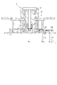
- FIG. 1 is a cross-sectional view showing an overall configuration of a detection device according to an embodiment of the present invention and a rotation controller to which the detection device detects a rotation angle.
- the detection device 1 according to the present embodiment is configured integrally with the rotation controller 2.
- the detection device 1 determines the rotation of the two potential meters 11A and 11B for detecting the rotation angle, the rotary gears 12A and 12B provided corresponding to the potential meters 11A and 11B, respectively, and the rotation controller 2.
- the sliding gear 13 transmitted to the rotary gears 12A and 12B is included.
- the rotation operator 2 includes a rotation operation member 21 that can be grasped and rotated by the user, and a rotation shaft portion 22.
- the rotation operation member 21 and the rotation shaft portion 22 are rotated about the rotation shaft Ax 2 .
- the rotation range of the rotation operator 2 is unlimited beyond 360 ° and can rotate both clockwise and counterclockwise.
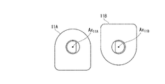
- FIG. 2A is a top view of the potentiometers 11A and 11B
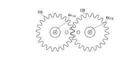
- FIG. 2B is a top view of the rotary gears 12A and 12B
- the potentiometers 11A and 11B are variable resistors and output output values according to the rotation angle of the detected portion (not shown).
- the detected portions of the potentiometers 11A and 11B are rotated in conjunction with each other around the rotation axes Ax 11A and Ax 11B , respectively.
- the rotary gears 12A and 12B have the same gear ratio, and the rotation of the rotary controller 2 transmitted from the sliding gear 13 is transmitted to the potential meters 11A and 11B to rotate the detected portions of the potential meters 11A and 11B.
- FIG. 1 is a top view of the potentiometers 11A and 11B
- FIG. 2B is a top view of the rotary gears 12A and 12B
- the potentiometers 11A and 11B are variable resistors and output output values according to the rotation angle of the
- the rotary gears 12A and 12B are rotated in conjunction with each other around the rotary shafts Ax 11A and Ax 11B , respectively. That is, the potentiometer 11A and the rotary gear 12A are positioned with the rotary shaft Ax 11A as the center of rotation, and the potential meter 11B and the rotary gear 12B are positioned with the rotary shaft Ax 11B as the center of rotation.
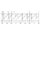
- FIG. 3 is a diagram illustrating the relationship between the rotation angle of the rotation controller 2 and the output values of the potentiometers 11A and 11B.
- the horizontal axis indicates the rotation angle of the rotation controller 2
- the vertical axis indicates the output value.
- the graph of the change in the output value VA of the potentiometer 11A is shown by the alternate long and short dash line
- the graph of the change in the output value V B of the potentiometer 11B is shown by the alternate long and short dash line. Since the rotary gears 12A and 12B rotate in opposite directions due to the mechanism, the graph shown in FIG. 3 is normalized. As shown in FIG.
- the output value VA of the potentiometer 11A and the output value VA of the potentiometer 11B change in conjunction with each other in different phases. This is because the potentiometers 11A and 11B are rotated in conjunction with each other in different phases.
- T1 indicates an upper limit value of the output values of the potentiometers 11A and 11B
- T2 indicates a lower limit value of the output values of the potentiometers 11A and 11B. That is, if it is T2 or more and less than T1, it is possible to detect the rotation angle of the rotation controller 2 based on the output value VA of the potentiometer 11A or the output value VA of the potentiometer 11B .
- the potentiometers 11A and 11B are assigned different detection ranges from the 360 ° rotation range of the rotation controller 2, and the entire 360 ° described above is determined by the respective detection ranges of the potentiometers 11A and 11B. Complements.
- the rotation shaft portion 22 is rotated around the rotation shaft Ax 2 .
- the rotation of the rotary shaft portion 22 is transmitted by the sliding gear 13 in the order of the rotary gear 12A and the rotary gear 12B.
- the rotary gears 12A and 12B rotate, the detected portions of the potentiometers 11A and 11B are rotated, and the output values VA and the output values VA are output from the potentiometers 11A and 11B , respectively.
- the sliding gear 13, the rotary gears 12A and 12B rotate in conjunction with each other, and function as a rotation transmission means for synchronously transmitting the rotation of the rotary controller 2 to the potentiometers 11A and 11B.
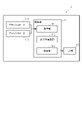
- FIG. 4 is a block diagram showing a functional configuration of the detection device 1 shown in FIGS. 1 to 3.
- the detection device 1 includes a control unit 14 and an output unit 15 in addition to the potentiometers 11A and 11B described with reference to FIGS. 1 to 3.
- the control unit 14 is mounted on the detection device 1 by means of, for example, a communication interface, a processor such as a CPU (Central Processing Unit), and a memory serving as a work area, and controls the operation of the detection device 1.
- the control unit 14 includes an acquisition unit 141 realized by the processor operating according to a program stored in a memory or received via a communication interface, an output value selection unit 142, and a detection unit 143.
- the acquisition unit 141 acquires the output value VA and the output value VA from the potentiometers 11A and 11B , respectively.
- the output value selection unit 142 selects either the output value VA or the output value BB acquired by the acquisition unit 141.
- the detection unit 143 detects the rotation angle of the rotation controller 2 based on the output value selected by the output value selection unit 142.
- the output unit 15 outputs the rotation angle detected by the detection unit 143.
- the selection of the output value by the output value selection unit 142 will be described with reference to FIG. 3 again.
- the selection of the output value by the output value selection unit 142 when the rotation controller 2 is rotated clockwise will be described.
- the potentiometers 11A and 11B are assigned different detection ranges from each other, and the respective detection ranges of the potentiometers 11A and 11B complement the entire 360 ° described above. Therefore, when one of the output values V A and the output value V B is outside the predetermined range defined by the upper limit value T1 and the lower limit value T2, the other output value is always within the predetermined range. ..
- the output value selection unit 142 compares the output value VA and the output value V B with the upper limit value T1 and the lower limit value T2, and the output value of one of the output value VA and the output value V B is predetermined. If it is out of range, select the other output value. That is, the output value selection unit 142 selects the output value V B when the output value V A is out of the predetermined range, and selects the output value V A when the output value V B is out of the predetermined range. .. Further, when the selected output value reaches the upper limit value T1, the output value selection unit 142 selects the unselected output value.
- the output value selection unit 142 selects the output value VA when the output value VA reaches the upper limit value T1, and selects the output value VA when the output value VA reaches the upper limit value T1 . select.
- the graph of the change of the output value VC selected by the output value selection unit 142 in this way is shown by a thick line in FIG.
- the selection of the output value by the output value selection unit 142 when the rotation operator 2 is rotated clockwise has been described, but the same applies when the rotation operator 2 is rotated counterclockwise. Can be thought of in the same way. That is, when the selected output value reaches the lower limit value T2, the output value selection unit 142 selects the unselected output value. That is, the output value selection unit 142 selects the output value VA when the output value VA reaches the lower limit value T2, and selects the output value VA when the output value VA reaches the lower limit value T2. select.
- the acquisition unit 141 acquires the output value VA and the output value VA from the potentiometers 11A and 11B , respectively (step S101).
- the output value selection unit 142 compares the acquired output value VA with the upper limit value T1 and the lower limit value T2, and determines whether the output value VA is the upper limit value T1 or more or the output value VA is less than the lower limit value T2. Whether or not, that is, whether or not the output value VA is out of the predetermined range is determined (step S102).
- the output value selection unit 142 selects the output value V B of the potentiometer 11B as a detection value used for detecting the rotation angle (step S103). ..
- the output value selection unit 142 compares the output value V B acquired in step S101 with the upper limit value T1 and the lower limit value T2, and outputs the output value V B. It is determined whether or not the value V B is equal to or greater than the upper limit value T1 or the output value V B is less than the lower limit value T2, that is, whether or not the output value V B is out of the predetermined range (step S104). When it is determined that the output value V B is out of the predetermined range (step S104YES), the output value selection unit 142 selects the output value V A of the potentiometer 11A as a detection value used for detecting the rotation angle (step S105). ..
- the output value selection unit 142 determines whether or not the movement directions of the output value V A and the output value V B acquired in step S101 are the same. By determining, it is determined whether or not the rotation direction of the rotation controller 2 is reversed (step S106). When it is determined that the moving directions of the output value VA and the output value VA are not the same (step S106NO ), it is determined that the rotation direction of the rotation controller 2 is reversed, and the output value selection unit 142 returns to step S101.
- step S106YES When it is determined that the moving directions of the output value VA and the output value VA are the same (step S106YES ), it is determined that the rotation direction of the rotation controller 2 is not reversed, and the output value selection unit 142 determines that the rotation direction is not inverted. It is determined whether or not V A is larger than the output value V B and
- the output value selection unit 142 When it is determined that the output value V A is larger than the output value V B and
- the value VA is selected as the detection value used to detect the rotation angle.
- the output value selection unit 142 has the output value V A as the output value V B. It is determined whether or not the value
- step S108NO When it is determined that the output value VA is larger than the output value VA or
- V A is smaller than the output value V B and
- the output value selection unit 142 returns to step S103 and outputs the potentiometer 11B.
- the value V B is selected as the detection value used to detect the rotation angle.
- the detection unit 143 detects the rotation angle of the rotation controller 2 based on the selected detection value (step S109). ), The output unit 15 outputs the rotation angle (step S110).
- the detection device 1 can detect and output the rotation angle of the rotation controller 2 by repeating the processes of steps S101 to S110 at predetermined time intervals.
- one of the output values of the potential meters 11A and 11B, which rotate in conjunction with each other in different phases corresponding to the rotation of the rotation controller 2 is selected.
- the rotation angle of the rotation controller 2 is detected based on the selected output value. Therefore, it is possible to realize a highly convenient detection device capable of detecting the rotation angle by complementarily using the output values of a plurality of potentiometers.
- the potentiometers 11A and 11B which are a plurality of potentiometers, are assigned different detection ranges from the rotation range of the rotation controller 2, and the plurality of potentiometers are used.
- the detection range of each of the potentiometers 11A and 11B complements the entire rotation range of the rotation controller 2. Therefore, even if a potentiometer that cannot cover the entire rotation range of the rotation controller 2 by one is used, it is possible to realize a detection device that can complement the entire rotation range of the rotation controller 2.
- the output value selection unit 142 is a second potentiometer when the output value of the first potentiometer is out of a predetermined range among the plurality of potentiometers 11A and 11B. Select the output value of the potentiometer. Therefore, it is possible to appropriately switch the output values of the plurality of potentiometers, select the output values, and detect the rotation angle of the rotation controller 2.
- each part of the detection device 1 of the above embodiment is an example, and the present invention is not limited to this example.
- the configuration including two potentiometers 11A and 11B as a plurality of potentiometers is shown, the configuration may include three or more potentiometers.
- the arrangement of the potentiometers 11A and 11B, which are a plurality of potentiometers is not limited to the example of the above embodiment.
- the potentiometers 11A and 11B may be arranged on both sides of the rotary controller 2.
- the detection device having the above-mentioned function may be used for any device and device for detecting the rotation angle of the rotation controller.
- the detection device of the present embodiment when used as an audio device, it can be expected to be effective in improving the operation feeling, durability, space saving, price reduction, and the like of the rotary controller.
Landscapes
- Physics & Mathematics (AREA)
- General Physics & Mathematics (AREA)
- Measurement Of Length, Angles, Or The Like Using Electric Or Magnetic Means (AREA)
Priority Applications (2)
| Application Number | Priority Date | Filing Date | Title |
|---|---|---|---|
| JP2022561722A JP7624455B2 (ja) | 2020-11-10 | 2020-11-10 | 回転操作子、検出方法およびプログラム |
| PCT/JP2020/041919 WO2022101978A1 (ja) | 2020-11-10 | 2020-11-10 | 検出装置、検出方法およびプログラム |
Applications Claiming Priority (1)
| Application Number | Priority Date | Filing Date | Title |
|---|---|---|---|
| PCT/JP2020/041919 WO2022101978A1 (ja) | 2020-11-10 | 2020-11-10 | 検出装置、検出方法およびプログラム |
Publications (1)
| Publication Number | Publication Date |
|---|---|
| WO2022101978A1 true WO2022101978A1 (ja) | 2022-05-19 |
Family
ID=81600854
Family Applications (1)
| Application Number | Title | Priority Date | Filing Date |
|---|---|---|---|
| PCT/JP2020/041919 Ceased WO2022101978A1 (ja) | 2020-11-10 | 2020-11-10 | 検出装置、検出方法およびプログラム |
Country Status (2)
| Country | Link |
|---|---|
| JP (1) | JP7624455B2 (cg-RX-API-DMAC7.html) |
| WO (1) | WO2022101978A1 (cg-RX-API-DMAC7.html) |
Citations (6)
| Publication number | Priority date | Publication date | Assignee | Title |
|---|---|---|---|---|
| JPS50151243U (cg-RX-API-DMAC7.html) * | 1974-05-31 | 1975-12-16 | ||
| JPS5415155A (en) * | 1977-07-06 | 1979-02-03 | Denki Onkyo Co Ltd | Multiphase potentiometer |
| US4423406A (en) * | 1981-03-31 | 1983-12-27 | Agency Of Industrial Science And Technology | Non-contact type potentiometer |
| JPH03117719U (cg-RX-API-DMAC7.html) * | 1990-03-16 | 1991-12-05 | ||
| JPH05107013A (ja) * | 1991-09-25 | 1993-04-27 | Nissan Motor Co Ltd | 回転角検出装置 |
| JP2005147893A (ja) * | 2003-11-17 | 2005-06-09 | Sakae Tsushin Kogyo Kk | 無接触型ポテンショメータ |
Family Cites Families (1)
| Publication number | Priority date | Publication date | Assignee | Title |
|---|---|---|---|---|
| JP2551095B2 (ja) * | 1988-03-17 | 1996-11-06 | 株式会社明電舎 | 連続回転角検出方法 |
-
2020
- 2020-11-10 JP JP2022561722A patent/JP7624455B2/ja active Active
- 2020-11-10 WO PCT/JP2020/041919 patent/WO2022101978A1/ja not_active Ceased
Patent Citations (6)
| Publication number | Priority date | Publication date | Assignee | Title |
|---|---|---|---|---|
| JPS50151243U (cg-RX-API-DMAC7.html) * | 1974-05-31 | 1975-12-16 | ||
| JPS5415155A (en) * | 1977-07-06 | 1979-02-03 | Denki Onkyo Co Ltd | Multiphase potentiometer |
| US4423406A (en) * | 1981-03-31 | 1983-12-27 | Agency Of Industrial Science And Technology | Non-contact type potentiometer |
| JPH03117719U (cg-RX-API-DMAC7.html) * | 1990-03-16 | 1991-12-05 | ||
| JPH05107013A (ja) * | 1991-09-25 | 1993-04-27 | Nissan Motor Co Ltd | 回転角検出装置 |
| JP2005147893A (ja) * | 2003-11-17 | 2005-06-09 | Sakae Tsushin Kogyo Kk | 無接触型ポテンショメータ |
Also Published As
| Publication number | Publication date |
|---|---|
| JPWO2022101978A1 (cg-RX-API-DMAC7.html) | 2022-05-19 |
| JP7624455B2 (ja) | 2025-01-30 |
Similar Documents
| Publication | Publication Date | Title |
|---|---|---|
| US6404354B1 (en) | Rotary controller for electrical or electronic apparatuses | |
| JP5707606B2 (ja) | 回転式入力装置及び電子機器 | |
| US10930445B2 (en) | Rotary operating device, method of controlling rotary operating device, and storage medium | |
| US5819597A (en) | In-car rotation detecting apparatus | |
| KR101149805B1 (ko) | 다방향 입력장치 | |
| JP4118114B2 (ja) | 力覚付与入力装置 | |
| US20040257339A1 (en) | Data processing system | |
| JPH04268914A (ja) | 可変スケール入力装置 | |
| US20040233162A1 (en) | Force-feedback input device | |
| JP7624455B2 (ja) | 回転操作子、検出方法およびプログラム | |
| JP2005332156A (ja) | 力覚付与型入力装置 | |
| JP4180455B2 (ja) | 力覚付与型入力装置 | |
| JPH0421117A (ja) | ダイヤル式入力装置 | |
| JP2005141541A (ja) | 携帯端末装置 | |
| JP3920618B2 (ja) | 力覚付与入力装置 | |
| JP4947653B2 (ja) | 節度装置 | |
| JP2005268283A (ja) | ダイアルスイッチ構造 | |
| CN110892179A (zh) | 用于在机动车中选择行驶挡级的设备和方法 | |
| JP5164853B2 (ja) | 自動車用途に対するギアチェンジ装置 | |
| JP6788789B2 (ja) | 変速機の入力装置 | |
| KR102639079B1 (ko) | 차량용 조작 제어 장치 및 그의 동작 방법 | |
| JP2010250421A (ja) | 操作装置 | |
| CN224150157U (zh) | 一种全周感应的旋钮式电子换挡操纵器 | |
| JP2016062309A (ja) | 手動パルスハンドル | |
| JP2000171350A (ja) | ロータリースイッチのフィーリング特性試験装置 |
Legal Events
| Date | Code | Title | Description |
|---|---|---|---|
| 121 | Ep: the epo has been informed by wipo that ep was designated in this application |
Ref document number: 20961506 Country of ref document: EP Kind code of ref document: A1 |
|
| ENP | Entry into the national phase |
Ref document number: 2022561722 Country of ref document: JP Kind code of ref document: A |
|
| NENP | Non-entry into the national phase |
Ref country code: DE |
|
| 122 | Ep: pct application non-entry in european phase |
Ref document number: 20961506 Country of ref document: EP Kind code of ref document: A1 |