WO2022097670A1 - 生体適合性材料及びその製造方法 - Google Patents
生体適合性材料及びその製造方法 Download PDFInfo
- Publication number
- WO2022097670A1 WO2022097670A1 PCT/JP2021/040544 JP2021040544W WO2022097670A1 WO 2022097670 A1 WO2022097670 A1 WO 2022097670A1 JP 2021040544 W JP2021040544 W JP 2021040544W WO 2022097670 A1 WO2022097670 A1 WO 2022097670A1
- Authority
- WO
- WIPO (PCT)
- Prior art keywords
- film
- calcium
- biocompatible material
- magnesium
- less
- Prior art date
Links
- 239000000560 biocompatible material Substances 0.000 title claims abstract description 93
- 238000000034 method Methods 0.000 title claims description 31
- 239000011575 calcium Substances 0.000 claims abstract description 147
- 229910052791 calcium Inorganic materials 0.000 claims abstract description 125
- OYPRJOBELJOOCE-UHFFFAOYSA-N Calcium Chemical compound [Ca] OYPRJOBELJOOCE-UHFFFAOYSA-N 0.000 claims abstract description 124
- 239000011777 magnesium Substances 0.000 claims abstract description 108
- FYYHWMGAXLPEAU-UHFFFAOYSA-N Magnesium Chemical compound [Mg] FYYHWMGAXLPEAU-UHFFFAOYSA-N 0.000 claims abstract description 92
- 229910052749 magnesium Inorganic materials 0.000 claims abstract description 92
- 239000012528 membrane Substances 0.000 claims abstract description 86
- 230000003746 surface roughness Effects 0.000 claims abstract description 86
- 239000000758 substrate Substances 0.000 claims description 185
- MCMNRKCIXSYSNV-UHFFFAOYSA-N Zirconium dioxide Chemical compound O=[Zr]=O MCMNRKCIXSYSNV-UHFFFAOYSA-N 0.000 claims description 88
- 238000012360 testing method Methods 0.000 claims description 53
- 239000000463 material Substances 0.000 claims description 44
- RTAQQCXQSZGOHL-UHFFFAOYSA-N Titanium Chemical compound [Ti] RTAQQCXQSZGOHL-UHFFFAOYSA-N 0.000 claims description 41
- 239000010936 titanium Substances 0.000 claims description 41
- 229910052719 titanium Inorganic materials 0.000 claims description 41
- 238000004544 sputter deposition Methods 0.000 claims description 29
- 210000000988 bone and bone Anatomy 0.000 claims description 19
- 238000007373 indentation Methods 0.000 claims description 15
- 238000004519 manufacturing process Methods 0.000 claims description 8
- 238000005477 sputtering target Methods 0.000 claims description 6
- 229910001069 Ti alloy Inorganic materials 0.000 claims description 5
- 238000004140 cleaning Methods 0.000 claims description 5
- 239000004053 dental implant Substances 0.000 claims description 5
- WAIPAZQMEIHHTJ-UHFFFAOYSA-N [Cr].[Co] Chemical class [Cr].[Co] WAIPAZQMEIHHTJ-UHFFFAOYSA-N 0.000 claims description 4
- 239000010935 stainless steel Substances 0.000 claims description 4
- 229910001256 stainless steel alloy Inorganic materials 0.000 claims 1
- 230000011164 ossification Effects 0.000 abstract description 9
- 239000010408 film Substances 0.000 description 291
- 239000000523 sample Substances 0.000 description 43
- 230000035882 stress Effects 0.000 description 33
- 230000015572 biosynthetic process Effects 0.000 description 32
- 239000007943 implant Substances 0.000 description 32
- 238000005259 measurement Methods 0.000 description 32
- 229910052586 apatite Inorganic materials 0.000 description 20
- VSIIXMUUUJUKCM-UHFFFAOYSA-D pentacalcium;fluoride;triphosphate Chemical compound [F-].[Ca+2].[Ca+2].[Ca+2].[Ca+2].[Ca+2].[O-]P([O-])([O-])=O.[O-]P([O-])([O-])=O.[O-]P([O-])([O-])=O VSIIXMUUUJUKCM-UHFFFAOYSA-D 0.000 description 20
- 238000002441 X-ray diffraction Methods 0.000 description 16
- 239000011521 glass Substances 0.000 description 12
- 238000001878 scanning electron micrograph Methods 0.000 description 12
- 238000002513 implantation Methods 0.000 description 11
- 239000011701 zinc Substances 0.000 description 10
- 239000013078 crystal Substances 0.000 description 9
- 239000012981 Hank's balanced salt solution Substances 0.000 description 8
- 230000000694 effects Effects 0.000 description 8
- 241001422033 Thestylus Species 0.000 description 7
- 238000001000 micrograph Methods 0.000 description 7
- 229910045601 alloy Inorganic materials 0.000 description 6
- 239000000956 alloy Substances 0.000 description 6
- 238000004458 analytical method Methods 0.000 description 6
- XKRFYHLGVUSROY-UHFFFAOYSA-N argon Substances [Ar] XKRFYHLGVUSROY-UHFFFAOYSA-N 0.000 description 6
- 238000007733 ion plating Methods 0.000 description 6
- 229910052751 metal Inorganic materials 0.000 description 6
- 239000002184 metal Substances 0.000 description 6
- 239000000243 solution Substances 0.000 description 6
- 238000010586 diagram Methods 0.000 description 5
- 238000011156 evaluation Methods 0.000 description 5
- 238000005498 polishing Methods 0.000 description 5
- 239000012890 simulated body fluid Substances 0.000 description 5
- 239000010409 thin film Substances 0.000 description 5
- VEXZGXHMUGYJMC-UHFFFAOYSA-N Hydrochloric acid Chemical compound Cl VEXZGXHMUGYJMC-UHFFFAOYSA-N 0.000 description 4
- HCHKCACWOHOZIP-UHFFFAOYSA-N Zinc Chemical compound [Zn] HCHKCACWOHOZIP-UHFFFAOYSA-N 0.000 description 4
- 230000002378 acidificating effect Effects 0.000 description 4
- 239000007864 aqueous solution Substances 0.000 description 4
- 229910052786 argon Inorganic materials 0.000 description 4
- 229910000765 intermetallic Inorganic materials 0.000 description 4
- 230000008646 thermal stress Effects 0.000 description 4
- 229910052725 zinc Inorganic materials 0.000 description 4
- 239000000919 ceramic Substances 0.000 description 3
- 238000006243 chemical reaction Methods 0.000 description 3
- 239000011248 coating agent Substances 0.000 description 3
- 238000000576 coating method Methods 0.000 description 3
- 230000000052 comparative effect Effects 0.000 description 3
- 229910003460 diamond Inorganic materials 0.000 description 3
- 239000010432 diamond Substances 0.000 description 3
- 239000010419 fine particle Substances 0.000 description 3
- 238000001755 magnetron sputter deposition Methods 0.000 description 3
- 230000036961 partial effect Effects 0.000 description 3
- 230000001681 protective effect Effects 0.000 description 3
- 238000000550 scanning electron microscopy energy dispersive X-ray spectroscopy Methods 0.000 description 3
- 125000006850 spacer group Chemical group 0.000 description 3
- 229910001220 stainless steel Inorganic materials 0.000 description 3
- 238000009864 tensile test Methods 0.000 description 3
- DGAQECJNVWCQMB-PUAWFVPOSA-M Ilexoside XXIX Chemical compound C[C@@H]1CC[C@@]2(CC[C@@]3(C(=CC[C@H]4[C@]3(CC[C@@H]5[C@@]4(CC[C@@H](C5(C)C)OS(=O)(=O)[O-])C)C)[C@@H]2[C@]1(C)O)C)C(=O)O[C@H]6[C@@H]([C@H]([C@@H]([C@H](O6)CO)O)O)O.[Na+] DGAQECJNVWCQMB-PUAWFVPOSA-M 0.000 description 2
- CPLXHLVBOLITMK-UHFFFAOYSA-N Magnesium oxide Chemical compound [Mg]=O CPLXHLVBOLITMK-UHFFFAOYSA-N 0.000 description 2
- OAICVXFJPJFONN-UHFFFAOYSA-N Phosphorus Chemical compound [P] OAICVXFJPJFONN-UHFFFAOYSA-N 0.000 description 2
- ZLMJMSJWJFRBEC-UHFFFAOYSA-N Potassium Chemical compound [K] ZLMJMSJWJFRBEC-UHFFFAOYSA-N 0.000 description 2
- 239000000853 adhesive Substances 0.000 description 2
- 230000001070 adhesive effect Effects 0.000 description 2
- -1 argon ions Chemical class 0.000 description 2
- 239000001506 calcium phosphate Substances 0.000 description 2
- 229910000389 calcium phosphate Inorganic materials 0.000 description 2
- 235000011010 calcium phosphates Nutrition 0.000 description 2
- 230000001054 cortical effect Effects 0.000 description 2
- 238000000151 deposition Methods 0.000 description 2
- 230000008021 deposition Effects 0.000 description 2
- 239000007789 gas Substances 0.000 description 2
- 239000012535 impurity Substances 0.000 description 2
- 238000000338 in vitro Methods 0.000 description 2
- 229910001425 magnesium ion Inorganic materials 0.000 description 2
- 239000002245 particle Substances 0.000 description 2
- 239000011574 phosphorus Substances 0.000 description 2
- 229910052698 phosphorus Inorganic materials 0.000 description 2
- 239000011591 potassium Substances 0.000 description 2
- 229910052700 potassium Inorganic materials 0.000 description 2
- 150000003839 salts Chemical class 0.000 description 2
- 238000010008 shearing Methods 0.000 description 2
- 238000004904 shortening Methods 0.000 description 2
- 239000011734 sodium Substances 0.000 description 2
- 229910052708 sodium Inorganic materials 0.000 description 2
- QORWJWZARLRLPR-UHFFFAOYSA-H tricalcium bis(phosphate) Chemical compound [Ca+2].[Ca+2].[Ca+2].[O-]P([O-])([O-])=O.[O-]P([O-])([O-])=O QORWJWZARLRLPR-UHFFFAOYSA-H 0.000 description 2
- XLYOFNOQVPJJNP-UHFFFAOYSA-N water Substances O XLYOFNOQVPJJNP-UHFFFAOYSA-N 0.000 description 2
- 101100255205 Caenorhabditis elegans rsa-2 gene Proteins 0.000 description 1
- JLVVSXFLKOJNIY-UHFFFAOYSA-N Magnesium ion Chemical compound [Mg+2] JLVVSXFLKOJNIY-UHFFFAOYSA-N 0.000 description 1
- 240000007594 Oryza sativa Species 0.000 description 1
- 235000007164 Oryza sativa Nutrition 0.000 description 1
- XUIMIQQOPSSXEZ-UHFFFAOYSA-N Silicon Chemical compound [Si] XUIMIQQOPSSXEZ-UHFFFAOYSA-N 0.000 description 1
- 208000008312 Tooth Loss Diseases 0.000 description 1
- QCWXUUIWCKQGHC-UHFFFAOYSA-N Zirconium Chemical compound [Zr] QCWXUUIWCKQGHC-UHFFFAOYSA-N 0.000 description 1
- 229910001297 Zn alloy Inorganic materials 0.000 description 1
- 230000002411 adverse Effects 0.000 description 1
- 238000005275 alloying Methods 0.000 description 1
- PNEYBMLMFCGWSK-UHFFFAOYSA-N aluminium oxide Inorganic materials [O-2].[O-2].[O-2].[Al+3].[Al+3] PNEYBMLMFCGWSK-UHFFFAOYSA-N 0.000 description 1
- 239000005313 bioactive glass Substances 0.000 description 1
- 230000036760 body temperature Effects 0.000 description 1
- 210000002449 bone cell Anatomy 0.000 description 1
- 229910001424 calcium ion Inorganic materials 0.000 description 1
- AOWKSNWVBZGMTJ-UHFFFAOYSA-N calcium titanate Chemical compound [Ca+2].[O-][Ti]([O-])=O AOWKSNWVBZGMTJ-UHFFFAOYSA-N 0.000 description 1
- 238000004364 calculation method Methods 0.000 description 1
- 150000001768 cations Chemical class 0.000 description 1
- 229910017052 cobalt Inorganic materials 0.000 description 1
- 239000010941 cobalt Substances 0.000 description 1
- GUTLYIVDDKVIGB-UHFFFAOYSA-N cobalt atom Chemical compound [Co] GUTLYIVDDKVIGB-UHFFFAOYSA-N 0.000 description 1
- 150000001875 compounds Chemical class 0.000 description 1
- 231100000433 cytotoxic Toxicity 0.000 description 1
- 230000001472 cytotoxic effect Effects 0.000 description 1
- 230000003013 cytotoxicity Effects 0.000 description 1
- 231100000135 cytotoxicity Toxicity 0.000 description 1
- 230000007423 decrease Effects 0.000 description 1
- 238000011161 development Methods 0.000 description 1
- 238000010828 elution Methods 0.000 description 1
- 238000010438 heat treatment Methods 0.000 description 1
- 238000007654 immersion Methods 0.000 description 1
- 238000001727 in vivo Methods 0.000 description 1
- 150000002484 inorganic compounds Chemical class 0.000 description 1
- 229910010272 inorganic material Inorganic materials 0.000 description 1
- 230000002452 interceptive effect Effects 0.000 description 1
- 150000002500 ions Chemical class 0.000 description 1
- 239000007788 liquid Substances 0.000 description 1
- 239000000395 magnesium oxide Substances 0.000 description 1
- 230000000873 masking effect Effects 0.000 description 1
- 239000002923 metal particle Substances 0.000 description 1
- 239000005300 metallic glass Substances 0.000 description 1
- 238000005272 metallurgy Methods 0.000 description 1
- 150000002739 metals Chemical class 0.000 description 1
- 239000000203 mixture Substances 0.000 description 1
- 230000000399 orthopedic effect Effects 0.000 description 1
- 230000002093 peripheral effect Effects 0.000 description 1
- 230000001737 promoting effect Effects 0.000 description 1
- 238000010791 quenching Methods 0.000 description 1
- 230000000171 quenching effect Effects 0.000 description 1
- 230000002829 reductive effect Effects 0.000 description 1
- 230000000717 retained effect Effects 0.000 description 1
- 235000009566 rice Nutrition 0.000 description 1
- 238000007788 roughening Methods 0.000 description 1
- 229910052710 silicon Inorganic materials 0.000 description 1
- 239000010703 silicon Substances 0.000 description 1
- 239000006104 solid solution Substances 0.000 description 1
- 238000009987 spinning Methods 0.000 description 1
- 238000005507 spraying Methods 0.000 description 1
- 230000003068 static effect Effects 0.000 description 1
- 238000012916 structural analysis Methods 0.000 description 1
- 239000000126 substance Substances 0.000 description 1
- 229910002058 ternary alloy Inorganic materials 0.000 description 1
- 229910052726 zirconium Inorganic materials 0.000 description 1
Images


Classifications
-
- A—HUMAN NECESSITIES
- A61—MEDICAL OR VETERINARY SCIENCE; HYGIENE
- A61L—METHODS OR APPARATUS FOR STERILISING MATERIALS OR OBJECTS IN GENERAL; DISINFECTION, STERILISATION OR DEODORISATION OF AIR; CHEMICAL ASPECTS OF BANDAGES, DRESSINGS, ABSORBENT PADS OR SURGICAL ARTICLES; MATERIALS FOR BANDAGES, DRESSINGS, ABSORBENT PADS OR SURGICAL ARTICLES
- A61L31/00—Materials for other surgical articles, e.g. stents, stent-grafts, shunts, surgical drapes, guide wires, materials for adhesion prevention, occluding devices, surgical gloves, tissue fixation devices
- A61L31/02—Inorganic materials
- A61L31/022—Metals or alloys
-
- A—HUMAN NECESSITIES
- A61—MEDICAL OR VETERINARY SCIENCE; HYGIENE
- A61C—DENTISTRY; APPARATUS OR METHODS FOR ORAL OR DENTAL HYGIENE
- A61C8/00—Means to be fixed to the jaw-bone for consolidating natural teeth or for fixing dental prostheses thereon; Dental implants; Implanting tools
-
- A—HUMAN NECESSITIES
- A61—MEDICAL OR VETERINARY SCIENCE; HYGIENE
- A61K—PREPARATIONS FOR MEDICAL, DENTAL OR TOILETRY PURPOSES
- A61K6/00—Preparations for dentistry
- A61K6/50—Preparations specially adapted for dental root treatment
- A61K6/58—Preparations specially adapted for dental root treatment specially adapted for dental implants
-
- A—HUMAN NECESSITIES
- A61—MEDICAL OR VETERINARY SCIENCE; HYGIENE
- A61L—METHODS OR APPARATUS FOR STERILISING MATERIALS OR OBJECTS IN GENERAL; DISINFECTION, STERILISATION OR DEODORISATION OF AIR; CHEMICAL ASPECTS OF BANDAGES, DRESSINGS, ABSORBENT PADS OR SURGICAL ARTICLES; MATERIALS FOR BANDAGES, DRESSINGS, ABSORBENT PADS OR SURGICAL ARTICLES
- A61L27/00—Materials for grafts or prostheses or for coating grafts or prostheses
- A61L27/02—Inorganic materials
- A61L27/04—Metals or alloys
- A61L27/045—Cobalt or cobalt alloys
-
- A—HUMAN NECESSITIES
- A61—MEDICAL OR VETERINARY SCIENCE; HYGIENE
- A61L—METHODS OR APPARATUS FOR STERILISING MATERIALS OR OBJECTS IN GENERAL; DISINFECTION, STERILISATION OR DEODORISATION OF AIR; CHEMICAL ASPECTS OF BANDAGES, DRESSINGS, ABSORBENT PADS OR SURGICAL ARTICLES; MATERIALS FOR BANDAGES, DRESSINGS, ABSORBENT PADS OR SURGICAL ARTICLES
- A61L27/00—Materials for grafts or prostheses or for coating grafts or prostheses
- A61L27/02—Inorganic materials
- A61L27/04—Metals or alloys
- A61L27/06—Titanium or titanium alloys
-
- A—HUMAN NECESSITIES
- A61—MEDICAL OR VETERINARY SCIENCE; HYGIENE
- A61L—METHODS OR APPARATUS FOR STERILISING MATERIALS OR OBJECTS IN GENERAL; DISINFECTION, STERILISATION OR DEODORISATION OF AIR; CHEMICAL ASPECTS OF BANDAGES, DRESSINGS, ABSORBENT PADS OR SURGICAL ARTICLES; MATERIALS FOR BANDAGES, DRESSINGS, ABSORBENT PADS OR SURGICAL ARTICLES
- A61L27/00—Materials for grafts or prostheses or for coating grafts or prostheses
- A61L27/28—Materials for coating prostheses
- A61L27/30—Inorganic materials
- A61L27/306—Other specific inorganic materials not covered by A61L27/303 - A61L27/32
-
- A—HUMAN NECESSITIES
- A61—MEDICAL OR VETERINARY SCIENCE; HYGIENE
- A61L—METHODS OR APPARATUS FOR STERILISING MATERIALS OR OBJECTS IN GENERAL; DISINFECTION, STERILISATION OR DEODORISATION OF AIR; CHEMICAL ASPECTS OF BANDAGES, DRESSINGS, ABSORBENT PADS OR SURGICAL ARTICLES; MATERIALS FOR BANDAGES, DRESSINGS, ABSORBENT PADS OR SURGICAL ARTICLES
- A61L27/00—Materials for grafts or prostheses or for coating grafts or prostheses
- A61L27/50—Materials characterised by their function or physical properties, e.g. injectable or lubricating compositions, shape-memory materials, surface modified materials
-
- A—HUMAN NECESSITIES
- A61—MEDICAL OR VETERINARY SCIENCE; HYGIENE
- A61L—METHODS OR APPARATUS FOR STERILISING MATERIALS OR OBJECTS IN GENERAL; DISINFECTION, STERILISATION OR DEODORISATION OF AIR; CHEMICAL ASPECTS OF BANDAGES, DRESSINGS, ABSORBENT PADS OR SURGICAL ARTICLES; MATERIALS FOR BANDAGES, DRESSINGS, ABSORBENT PADS OR SURGICAL ARTICLES
- A61L31/00—Materials for other surgical articles, e.g. stents, stent-grafts, shunts, surgical drapes, guide wires, materials for adhesion prevention, occluding devices, surgical gloves, tissue fixation devices
- A61L31/08—Materials for coatings
- A61L31/082—Inorganic materials
- A61L31/088—Other specific inorganic materials not covered by A61L31/084 or A61L31/086
-
- A—HUMAN NECESSITIES
- A61—MEDICAL OR VETERINARY SCIENCE; HYGIENE
- A61C—DENTISTRY; APPARATUS OR METHODS FOR ORAL OR DENTAL HYGIENE
- A61C8/00—Means to be fixed to the jaw-bone for consolidating natural teeth or for fixing dental prostheses thereon; Dental implants; Implanting tools
- A61C8/0012—Means to be fixed to the jaw-bone for consolidating natural teeth or for fixing dental prostheses thereon; Dental implants; Implanting tools characterised by the material or composition, e.g. ceramics, surface layer, metal alloy
-
- A—HUMAN NECESSITIES
- A61—MEDICAL OR VETERINARY SCIENCE; HYGIENE
- A61L—METHODS OR APPARATUS FOR STERILISING MATERIALS OR OBJECTS IN GENERAL; DISINFECTION, STERILISATION OR DEODORISATION OF AIR; CHEMICAL ASPECTS OF BANDAGES, DRESSINGS, ABSORBENT PADS OR SURGICAL ARTICLES; MATERIALS FOR BANDAGES, DRESSINGS, ABSORBENT PADS OR SURGICAL ARTICLES
- A61L2420/00—Materials or methods for coatings medical devices
- A61L2420/06—Coatings containing a mixture of two or more compounds
-
- A—HUMAN NECESSITIES
- A61—MEDICAL OR VETERINARY SCIENCE; HYGIENE
- A61L—METHODS OR APPARATUS FOR STERILISING MATERIALS OR OBJECTS IN GENERAL; DISINFECTION, STERILISATION OR DEODORISATION OF AIR; CHEMICAL ASPECTS OF BANDAGES, DRESSINGS, ABSORBENT PADS OR SURGICAL ARTICLES; MATERIALS FOR BANDAGES, DRESSINGS, ABSORBENT PADS OR SURGICAL ARTICLES
- A61L2430/00—Materials or treatment for tissue regeneration
- A61L2430/02—Materials or treatment for tissue regeneration for reconstruction of bones; weight-bearing implants
-
- A—HUMAN NECESSITIES
- A61—MEDICAL OR VETERINARY SCIENCE; HYGIENE
- A61L—METHODS OR APPARATUS FOR STERILISING MATERIALS OR OBJECTS IN GENERAL; DISINFECTION, STERILISATION OR DEODORISATION OF AIR; CHEMICAL ASPECTS OF BANDAGES, DRESSINGS, ABSORBENT PADS OR SURGICAL ARTICLES; MATERIALS FOR BANDAGES, DRESSINGS, ABSORBENT PADS OR SURGICAL ARTICLES
- A61L2430/00—Materials or treatment for tissue regeneration
- A61L2430/12—Materials or treatment for tissue regeneration for dental implants or prostheses
Definitions
- the present invention relates to a biocompatible material having a membrane comprising magnesium and optionally calcium.
- the present invention relates to biocompatible materials having a film comprising magnesium and optionally calcium having a given surface roughness, a given adhesion and / or a given hardness.
- the present invention also relates to a method for producing the biocompatible material.
- Treatment of teeth with implants is attracting attention as a kind of treatment method for tooth loss from young people to the elderly.
- metallic titanium, titanium alloy, or ceramic zirconia which has a relatively low adverse effect on the living body, is used.
- Non-Patent Document 1 and Non-Patent Document 2 show that forming apatite on the surface of a root implant is effective for forming surrounding bone, and apatite is applied to the surface of a root implant before implantation. It discloses that apatite is formed by spraying or apatite is formed by spattering.
- apatite is also formed on a titanium implant, but a calcium-containing film is chemically formed on the implant, and a calcium-containing film is used as an intermediate layer on the apatite. It is disclosed that the adhesion is enhanced by forming apatite in calcium.
- Non-Patent Document 3 discloses that it is effective to generate an appropriate pressure between the root implant and the alveolar bone in order to promote secondary fixation. Therefore, Non-Patent Document 3 discloses that it is necessary to tighten the root implant with an appropriate torque at the time of tightening at the time of initial fixing.
- the apatite film formed before embedding described in Non-Patent Document 1, Non-Patent Document 2, Patent Document 1 and Patent Document 2 described above has a low hardness and / or Due to insufficient adhesion, it was easily peeled off during tightening and embedding, and its function could not be fully fulfilled.
- Patent Document 3 uses metal for the core (base) of the implant and silicon, sodium, magnesium, calcium on the surface instead of apatite in order to maintain the strength of the implant and improve the bonding function with the bone at the same time. Discloses that a film of bioactive glass containing an oxide of potassium is formed. However, since this film is made of inorganic glass or an inorganic compound, it has a drawback of being brittle although it is hard.
- Patent Document 4 attempts to promote bone formation by appropriately roughening the surface of a ceramic tooth root implant such as zirconia. However, in this case, although it can be tightened independently of the detachment of the membrane, bone formation is not sufficient.
- Patent Document 5 discloses that in a tooth root implant, the implant is covered and protected with a protective film in order to utilize the active surface of the base material. This protective membrane is designed to disappear after implantation for the purpose of maintaining aesthetics, but the membrane itself has no component or function to promote bone formation.
- Patent Document 6 forms a protective film on the surface for the purpose of protecting the active surface of the implant substrate for tooth roots, and the components of the film are salts that generate cations of sodium, potassium, magnesium, and calcium. Disclose that it consists of. However, in the case of salt, the strength and adhesion of the film required for implantation are not sufficient.
- Non-Patent Document 4 discloses an orthopedic implant in which a metal pure magnesium film is formed on the surface by an ion plating method instead of apatite.
- a metal pure magnesium film is formed on the surface by an ion plating method instead of apatite.
- the ability to form apatite is not sufficient because calcium, which is the main component of apatite, does not exist.
- the arc ion plating used here since the particles forming the film are large, the surface roughness is large, and it is difficult to control the roughness. Further, in this method, even if calcium is further used as a target for alloying, a film is formed as a cluster, so that intermetallic compounds such as those in the film are formed and become brittle.
- Non-Patent Document 5 proposes that a ternary alloy of Mg—Ca—Zn is useful as a core (base) of an implant as a biodegrading material.
- Mg is considered as the main alloy
- the solid solution limit is 1% or less, and if it is added more than that, an intermetallic compound such as Mg 2 Ca is formed. Therefore, the Ca content of these alloys is at most 5% or less, and there is a possibility that intermetallic compounds may remain in the body in addition to Mg ions and Ca ions.
- Non-Patent Document 6 discloses that Mg-Ca-Zn to which Ca is added up to 15% is produced as an amorphous ribbon by a high-speed rotary quenching method (spinning method) from a high temperature.
- a high-speed rotary quenching method spininning method
- about 7% of intermetallic compounds are formed, it is not easy to produce a uniform amorphous substance, and the shape and size are limited.
- Non-Patent Document 7 it is shown by Non-Patent Document 7 that although a similar method has been attempted to produce a Ca—Mg—Zn alloy containing Ca as a main metal in order to enhance the effect of Ca, uniform amorphous formation has not been achieved. ing.
- Non-Patent Document 8 and Non-Patent Document 9 disclose that the Mg—Ca—Zn ternary system to which Ca is added from 4% by weight to 24% by weight is produced as an amorphous thin film by sputtering. These thin films contain at least 30% by weight of Zn to facilitate the formation of an amorphous state, but Zn ions are cytotoxic, and the higher the amount of Zn, the stronger the cytotoxicity. It is shown by Non-Patent Document 9.
- an object of the present invention is to provide a biocompatible material having a membrane that realizes bone formation around the membrane in a relatively short period of time. Further, an object of the present invention is biocompatibility having a film having a relatively smooth surface roughness, which is suitable for embedding or tightening with an appropriate embedding torque in addition to or in addition to the above-mentioned object. The purpose is to provide sex materials.
- ⁇ A2> A biocompatible material having a membrane having magnesium and optionally calcium, wherein the membrane contains 0 to 40% by weight of calcium, where the total weight of magnesium and calcium is 100% by weight.
- the difference between the arithmetic mean height Sa1 of the surface roughness of the film and the arithmetic mean height Sa2 of the surface roughness without the film is 300 nm or less, preferably 200 nm or less, more preferably 150 nm or less.
- the arithmetic average height Sa1 of the surface roughness of the film is preferably 2 ⁇ m or less, preferably 1 ⁇ m or less.
- the biocompatible material having the characteristics of any one, two, or all of the following i) to iii).
- the hardness obtained by the indentation test is 0.4 GPa or more, preferably 0.9 GPa or more, and more preferably 1.2 GPa or more.
- ii) Relationship between critical load Wc (N) and film thickness t ( ⁇ m) Wc / t is 1 N / ⁇ m or more, more preferably 2 N / ⁇ m or more.
- the critical shear stress at the interface between the film and the substrate is 80 MPa or more, preferably 160 MPa or more.
- ⁇ A5> In the above ⁇ A4>, a) The arithmetic average height Sa1 of the surface roughness of the film is 2 ⁇ m or less, preferably 1 ⁇ m or less, and / or b) The arithmetic average height Sa1 of the surface roughness of the film and the surface without the film. It is preferable that the difference between the surface roughness and the arithmetic mean height Sa2 is 300 nm or less, preferably 200 nm or less, and more preferably 150 nm or less.
- the average thickness of the film is preferably 0.10 to 30 ⁇ m.
- the average thickness of the film corresponding to the contact portion with the bone and its vicinity is preferably 0.10 to 30 ⁇ m, preferably 0.20 to 20 ⁇ m, and more preferably 0.40 to 15 ⁇ m.
- the film is essentially made of magnesium only.
- the film is made of only magnesium.
- the membrane has magnesium and calcium, and the membrane has 0% by weight of calcium, where the total weight of magnesium and calcium is 100% by weight. It is preferable to have 40% by weight or less, preferably 0.8 to 35% by weight, more preferably 5 to 30% by weight, and most preferably 15 to 25% by weight.
- the membrane is essentially composed of only magnesium and calcium.
- the film is composed of only magnesium and calcium.
- the film is Mg 2 Ca free.
- the film has an amorphous portion.
- the film is preferably made essentially of amorphous material, and preferably made of only amorphous material.
- the biocompatible material has a biocompatible substrate, and the biocompatible substrate is pure titanium, zirconia, cobalt-chromium alloy, stainless steel and titanium. It is preferably at least one selected from the group consisting of alloys.
- the biocompatible material is an artificial bone material, an intraosseous fixation device material, a dental implant material, an orthodontic anchor screw material, an intramedullary nail material, and the like. And one selected from the group consisting of interbody fixation materials.
- interbody fixation materials For example, artificial bones, pins, wires, bolts, screws, washers, intramedullary nails, vertebral body spacers and the like are preferable.
- the shape of the biocompatible material is cylindrical, conical, conical, and conical, and a screw-shaped screw portion is provided as a part of the shape. It is preferably one selected from the group consisting of shapes, rectangular parallelepipeds and cubes, block shapes such as rectangular parallelepipeds and cubes having a partially inclined surface, and wedge shapes.
- Step of preparing a biocompatible substrate (B) A step of preparing a sputter target having magnesium and optionally calcium; (C) A step of cleaning the surface of the biocompatible substrate in vacuum; and (D) Using the sputtering target, the temperature of the biocompatible substrate obtained in the step (C) is preferably 130 ° C. or lower. Is 90 ° C. or lower, more preferably 60 ° C. or lower, and a step of forming a film having magnesium and optionally calcium on the biocompatible substrate by sputtering; A biocompatible material having a membrane having magnesium and optionally calcium, wherein the membrane has 0 to 40 calcium, where the total weight of magnesium and calcium is 100% by weight. A method for producing a biocompatible material, which obtains a biocompatible material having% by weight.
- a) The arithmetic average height Sa1 of the surface roughness of the film is 2 ⁇ m or less, preferably 1 ⁇ m or less, and / or b) The arithmetic average height Sa1 of the surface roughness of the film and the film are not provided. It is preferable that the difference between the surface roughness of the surface and the arithmetic mean height Sa2 is 300 nm or less, preferably 200 nm or less, and more preferably 150 nm or less.
- the film may have the characteristics of any one, two, or all of the following i) to iii): i) The hardness obtained by the indentation test is 0.4 GPa or more, preferably 0.9 GPa or more, and more preferably 1.2 GPa or more. ii) Relationship between critical load Wc (N) and film thickness t ( ⁇ m) Wc / t is 1 N / ⁇ m or more, more preferably 2 N / ⁇ m or more. iii) The critical shear stress at the interface between the film and the substrate is 80 MPa or more, preferably 160 MPa or more.
- the average thickness of the film is preferably 0.10 to 30 ⁇ m, preferably 0.20 to 20 ⁇ m, and more preferably 0.40 to 15 ⁇ m. ..
- ⁇ B2> A biocompatible material having a membrane having magnesium and optionally calcium, wherein the membrane contains 0 to 40% by weight of calcium, where the total weight of magnesium and calcium is 100% by weight.
- the difference between the arithmetic mean height Ra1 of the line roughness of the film and the arithmetic mean height Ra2 of the line roughness of the surface without the film is 300 nm or less, preferably 200 nm or less, more preferably 150 nm or less.
- the arithmetic average height Ra1 of the line roughness of the film is preferably 2 ⁇ m or less, preferably 1 ⁇ m or less and B or less.
- the film has the characteristics of any one, two, or all of the following i) to iii): i)
- the hardness obtained by the indentation test is 0.4 GPa or more, preferably 0.9 GPa or more, and more preferably 1.2 GPa or more.
- ii) Relationship between critical load Wc (N) and film thickness t ( ⁇ m) Wc / t is 1 N / ⁇ m or more, more preferably 2 N / ⁇ m or more.
- the critical shear stress at the interface between the film and the substrate is 80 MPa or more, preferably 160 MPa or more.
- ⁇ B5> In any of the above ⁇ B1> to ⁇ B4>, c) The arithmetic average height Sa1 of the surface roughness of the film is 2 ⁇ m or less, preferably 1 ⁇ m or less, and / or d) The arithmetic average height Sa1 of the surface roughness of the film and the surface without the film. It is preferable that the difference between the surface roughness and the arithmetic mean height Sa2 is 300 nm or less, preferably 200 nm or less, and more preferably 150 nm or less.
- the average thickness of the film is preferably 0.10 to 30 ⁇ m. In particular, the average thickness of the film corresponding to the contact portion with the bone and its vicinity is preferably 0.10 to 30 ⁇ m, preferably 0.20 to 20 ⁇ m, and more preferably 0.40 to 15 ⁇ m.
- the film is essentially made of magnesium only.
- the film is made of only magnesium.
- the membrane has magnesium and calcium, and the membrane has 0% by weight of calcium, where the total weight of magnesium and calcium is 100% by weight. It is preferable to have 40% by weight or less, preferably 0.8 to 35% by weight, more preferably 5 to 30% by weight, and most preferably 15 to 25% by weight.
- the membrane is essentially composed of only magnesium and calcium.
- the film is composed of only magnesium and calcium.
- the film is Mg 2 Ca free.
- the film has an amorphous portion.
- the film is preferably made essentially of amorphous material, and preferably made of only amorphous material.
- the biocompatible material has a biocompatible substrate, and the biocompatible substrate is pure titanium, zirconia, cobalt-chromium alloy, stainless steel and titanium. It is preferably at least one selected from the group consisting of alloys.
- the biocompatible material is an artificial bone material, an intraosseous fixation device material, a dental implant material, an orthodontic anchor screw material, an intramedullary nail material, and the like. And one selected from the group consisting of interbody fixation materials.
- interbody fixation materials For example, artificial bones, pins, wires, bolts, screws, washers, intramedullary nails, vertebral body spacers and the like are preferable.
- the shape of the biocompatible material is cylindrical, conical, conical, and conical, and a screw-shaped screw portion is provided as a part of the shape. It is preferably one selected from the group consisting of shapes, rectangular parallelepipeds and cubes, block shapes such as rectangular parallelepipeds and cubes having a partially inclined surface, and wedge shapes.
- Step of preparing a biocompatible substrate (B) A step of preparing a sputter target having magnesium and optionally calcium; (C) A step of cleaning the surface of the biocompatible substrate in vacuum; and (D) Using the sputtering target, the temperature of the biocompatible substrate obtained in the step (C) is preferably 130 ° C. or lower. Is 90 ° C. or lower, more preferably 60 ° C. or lower, and a step of forming a film having magnesium and optionally calcium on the biocompatible substrate by sputtering; A biocompatible material having a membrane having magnesium and optionally calcium, wherein the membrane has 0 to 40 calcium, where the total weight of magnesium and calcium is 100% by weight.
- Has% by weight a) The arithmetic average height Ra1 of the line roughness of the film is 2 ⁇ m or less, preferably 1 ⁇ m or less, and / or b) The arithmetic average height Ra1 of the line roughness of the film and the film are not provided.
- a method for producing a biocompatible material which obtains a biocompatible material having a surface roughness difference from the arithmetic mean height Ra2 of 300 nm or less, preferably 200 nm or less, more preferably 150 nm or less.
- the arithmetic average height Sa1 of the surface roughness of the film is 2 ⁇ m or less, preferably 1 ⁇ m or less, and / or d)
- the arithmetic average height Sa1 of the surface roughness of the film and the film are not provided. It is preferable that the difference between the surface roughness of the surface and the arithmetic mean height Sa2 is 300 nm or less, preferably 200 nm or less, and more preferably 150 nm or less.
- the film may have the characteristics of any one, two, or all of the following i) to iii): i) The hardness obtained by the indentation test is 0.4 GPa or more, preferably 0.9 GPa or more, and more preferably 1.2 GPa or more. ii) Relationship between critical load Wc (N) and film thickness t ( ⁇ m) Wc / t is 1 N / ⁇ m or more, more preferably 2 N / ⁇ m or more. iii) The critical shear stress at the interface between the film and the substrate is 80 MPa or more, preferably 160 MPa or more.
- the average thickness of the film is preferably 0.10 to 30 ⁇ m, preferably 0.20 to 20 ⁇ m, and more preferably 0.40 to 15 ⁇ m. ..
- a biocompatible material having a membrane around which bone formation is realized in a relatively short period of time it is possible to provide a biocompatible material having a membrane around which bone formation is realized in a relatively short period of time. Further, according to the present invention, a biocompatible material having a film having a relatively smooth surface roughness suitable for embedding or tightening with an appropriate embedding torque in addition to or in addition to the above-mentioned effects. Can be provided.
- a biocompatible material having a film having adhesion and / or hardness that can withstand embedding or tightening with an appropriate embedding torque in addition to or in addition to the above-mentioned effects is provided.
- film formation using the plate-like substrate using zirconia (the value of Ra1 with the diagonal line, the diagonal line). None is the value of Ra2).
- film formation using the plate-like substrate using zirconia (the value of Sa1 with the diagonal line, the diagonal line). None is the value of Sa2).
- the scanning electron microscope image (SEM image) in the cross-sectional direction of the film about AC1-C0, AC1-C10, AC1-C20 and AC1-C30 which formed the film using the glass substrate is shown.
- film using the plate-like substrate using titanium is shown.
- film using the plate-like substrate using zirconia is shown. It is a figure which shows the result of the X-ray diffraction analysis about the film of AC1-C0, AC1-C10, AC1-C20 and AC1-C30 which formed the film
- the present application is a biocompatible material having a membrane comprising magnesium and optionally calcium, wherein the membrane contains 0-40% by weight of calcium, where the total weight of magnesium and calcium is 100% by weight.
- the amount of calcium exceeds 0% by weight and is 40% by weight or less, preferably 0.8 to 35% by weight, more preferably 5 to 30% by weight, and most preferably 15 to 25% by weight.
- the amount of calcium is more preferably 5 to 35% by weight, still more preferably 15 to 35% by weight, and most preferably 25 to 35% by weight.
- the present invention provides a biocompatible material in which a) the arithmetic mean height Ra1 of the line roughness of the film is 2 ⁇ m or less, preferably 1 ⁇ m or less. Further, in other aspects, b) the difference between the arithmetic average height Ra1 of the line roughness of the film and the arithmetic average height Ra2 of the surface roughness of the surface without the film is preferably 300 nm or less. Provides a biocompatible material of 200 nm or less, more preferably 150 nm or less. Further, the present invention provides a biocompatible material in which c) the arithmetic mean height Sa1 of the surface roughness of the film is 2 ⁇ m or less, preferably 1 ⁇ m or less.
- the difference between the arithmetic average height Sa1 of the surface roughness of the film and the arithmetic average height Sa2 of the surface roughness of the surface without the film is preferably 300 nm or less.
- a biocompatible material of 200 nm or less, more preferably 150 nm or less.
- the biocompatible material may have the characteristics of a) and / or b) and the characteristics of c) and / or d).
- the film may have the characteristics of any one, two, or all of the following i) to iii): i)
- the hardness obtained by the indentation test is 0.4 GPa or more, preferably 0.9 GPa or more, and more preferably 1.2 GPa or more.
- ii) Relationship between critical load Wc (N) and film thickness t ( ⁇ m) Wc / t is 1 N / ⁇ m or more, more preferably 2 N / ⁇ m or more.
- the critical shear stress at the interface between the film and the substrate is 80 MPa or more, preferably 160 MPa or more.
- the "biocompatibility" in the “biocompatible material” of the present invention refers to a characteristic that is retained in a living body and is not considered to be a biosafety problem.
- the biocompatible material of the present invention has the above-mentioned characteristics a) and / or b), specifically, an arithmetic average height Ra1 of a predetermined line roughness, and an arithmetic average height Ra1 and Ra2 of a predetermined line roughness. It is preferable to have a predetermined critical load which is an index of a predetermined adhesion, a predetermined hardness, and / or a predetermined critical shear stress at the interface between the film and the substrate.
- the biocompatible material of the present invention has the above-mentioned characteristics c) and / or d), specifically, the arithmetic average height Sa1 of a predetermined surface roughness, and the arithmetic average heights Sa1 and Sa2 of the surface roughness. It is preferable to have a predetermined difference, a predetermined critical load which is an index of a predetermined adhesion, a predetermined hardness, and / or a predetermined critical shear stress at the interface between the film and the substrate. Further, the biocompatible material of the present invention may have any one, two, or three, or all of the above-mentioned properties a) to d).
- the arithmetic mean height Ra1 of the line roughness of the film of the biocompatible material of the present invention is preferably 2 ⁇ m or less, preferably 1 ⁇ m or less.
- the surface having the film that is, the arithmetic mean height Ra1 of the line roughness of the film can be measured according to JIS B0601: 2013.
- the standard length and the evaluation length are defined according to the classification of Ra value.
- the reference length and the evaluation length of 0.1 ⁇ Ra ( ⁇ m) ⁇ 2 are 0.8 mm and 2.0 mm, respectively. If the reference length cannot be measured continuously due to the interference between the stylus and the object to be measured, use the reference length in the category lower than the Ra value of the object and measure the total number of times that it exceeds the evaluation length. Then, the average value can be Ra.
- the surface of the biocompatible substrate in the biocompatible material of the present application may be ground in a certain direction or the entire surface may be polished. When polishing to the whole, the roughness of the surface becomes almost uniform, while when grinding in a certain direction, scanning the probe light along the directional roughness is prone to measurement errors.
- the value may differ between the arithmetic mean surface of the line roughness along the direction and the arithmetic mean height of the line roughness in the direction perpendicular to the direction.
- the arithmetic mean height of the line roughness of the film in the present application refers to a value measured by moving the probe in the circumferential direction when the biocompatible substrate has a cylindrical shape or a screw shape. In the case of other shapes, it is better to measure in all directions, but for example, it refers to the value measured in four directions in 45 ° increments and averaged.
- the "surface without a film” in the "arithmetic mean height Ra2 of the line roughness of the surface without a film” means the surface of the substrate before the film formation or when the film is removed after the film formation. Refers to the surface of the substrate.
- the membrane of the present application comprises magnesium and optionally calcium, as described above. The membrane can generally be removed almost completely by immersing it in a weakly acidic aqueous solution or water.
- the biocompatible substrate in the biocompatible material of the present application is not eroded by the weakly acidic aqueous solution used for removing the film.
- the arithmetic mean height Ra2 of the line roughness of the surface of the substrate before the film formation and the arithmetic average height Ra2'of the surface of the substrate when the film is removed after the film formation are substantially the same.
- the difference between the arithmetic mean height Ra1 of the line roughness of the film and the arithmetic mean height RSa2 of the surface roughness without the film is 300 nm or less, preferably 200 nm or less, more preferably 150 nm on a certain surface. It should be as follows.
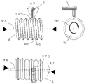
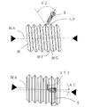
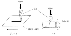
- FIGS. 1 and 2 exemplify a case where the roughness of the threaded portion is measured when the object to be measured has a substantially cylindrical shape and has a threaded portion of a screw.
- the screw is attached to a device having a rotation mechanism by using a chuck or the like so that the screw shaft WA of the screw portion W becomes the rotation shaft.
- the tip SP of the probe of the stylus S of the roughness measuring device is set perpendicularly to the valley portion WG of the screw, and the measuring object W is rotated at a constant speed in the rotation direction WR while the stylus is fixed, so that the measurement is performed on a flat surface.
- the measurement length ST1 can perform the measurement along the thread valley WG.
- the frictional force on the flank surface of the screw has the greatest effect on the embedding torque when embedding the screw. Therefore, the roughness of the screw flank surface WF becomes important.
- the stylus S or the rotation axis WA of the screw is tilted and arranged so that the angle A2 between the probe SP and the flank surface is as perpendicular as possible. preferable.
- the measurement length ST2 is measured along the circumferential direction of the flank surface of the screw. In this way, even in the case of a screw shape, the line roughness of the screw valley WG and the flank surface WF of the screw is desired by setting the rotation speed, the rotation radius of the measurement point, and the rotation time. Measurement according to the measurement length (ST1 or ST2) becomes possible.
- the measurement length ST1 or ST2 is large, it is preferable to use a lead screw having the same pitch as the screw to be measured and to provide a mechanism for sliding the shaft WA in the traveling direction of the screw (left direction in FIGS. 1 and 2).
- the angle A3 of the tip SP of the probe is preferably 60 degrees or less in consideration of the width of the thread valley WG so as not to interfere with the thread thread or the flank portion WF.
- the arithmetic average height Sa1 of the surface roughness of the film of the biocompatible material of the present invention is preferably 2 ⁇ m or less, preferably 1 ⁇ m or less.
- the surface having the film that is, the arithmetic mean height Sa1 of the surface roughness of the film can be measured according to ISO25178.
- the surface roughness is measured by laser light, it is possible to acquire 10,000 or more measurement points with a measurement range of 100 ⁇ m ⁇ 100 ⁇ m.
- the arithmetic mean height can be calculated by performing shape removal by a quadratic polynomial on the calibration surface leveled by the least squares method and without using a filter for separating the wavelength component of the contour curve. Further, it is preferable to measure the total measurement distance in one direction more than the number of times that the evaluation length conforms to JIS0633 / ISO4288 and obtain the average value.
- the surface of the biocompatible substrate in the biocompatible material of the present application may be ground in a certain direction or the entire surface may be polished. When polishing to the whole, the roughness of the surface becomes almost uniform, while when grinding in a certain direction, scanning the probe light along the directional roughness is prone to measurement errors.
- the value may differ between the arithmetic mean surface along that direction and the arithmetic mean height of the surface roughness in the direction perpendicular to that direction.
- the arithmetic mean height of the surface roughness of the film is the surface roughness obtained by scanning the probe light in three directions of parallel, perpendicular, and diagonally about 45 ° with respect to the center line of the shape of the biocompatible material. Arithmetic mean The value when the surface roughness is measured and the direction with the lowest roughness is measured.
- the "surface without a film” in the "arithmetic mean height Sa2 of the surface roughness of the surface without a film” means the surface of the substrate before the film formation or when the film is removed after the film formation. Refers to the surface of the substrate.
- the membrane of the present application comprises magnesium and optionally calcium, as described above. The membrane can generally be removed almost completely by immersing it in a weakly acidic aqueous solution or water.
- the biocompatible substrate in the biocompatible material of the present application is not eroded by the weakly acidic aqueous solution used for removing the film.
- the arithmetic mean height Sa2 of the surface roughness of the surface of the substrate before the film formation and the arithmetic mean height Sa2'of the surface of the substrate when the film is removed after the film formation are substantially the same.
- the difference between the arithmetic average height Sa1 of the surface roughness of the film and the arithmetic average height Sa2 of the surface roughness of the surface without the film is 300 nm or less, preferably 200 nm or less, more preferably. It is preferably 150 nm or less.
- the film has the characteristics of any one, two, or all of the following i) to iii) in a certain aspect.
- the hardness obtained by the indentation test is 0.4 GPa or more, preferably 0.9 GPa or more, and more preferably 1.2 GPa or more.
- Relationship between critical load Wc (N) and film thickness t ( ⁇ m) Wc / t is 1 N / ⁇ m or more, more preferably 2 N / ⁇ m or more.
- the critical shear stress at the interface between the film and the substrate is 80 MPa or more, preferably 160 MPa or more.
- the hardness obtained by the indentation test of the film is preferably 0.4 GPa or more, preferably 0.9 GPa or more, and more preferably 1.2 GPa or more.
- the critical load Wc is a load when a brittle crack occurs without showing ductility of the film, a load when the film is partially peeled off, or a load when the film is scraped and the substrate is exposed.
- the Wc / t of the film (in the formula, Wc is a critical load (N) and t is a film thickness ( ⁇ m)) is 1 N / ⁇ m or more, more preferably 2 N / ⁇ m. That should be the above.
- the film thickness is 5 ⁇ m
- the film is preferably characterized by having a critical load of 5 N or more, preferably 10 N or more.
- the scratch test uses a device normally used for the scratch test and uses a rockwell indenter having a diameter of 0.8 mm to maximize the double of the load to which the substrate is exposed, or the film is partially covered.
- the load is applied in the range of 0 to 8 kg weight, for example, to the range where the maximum is twice the load that is peeled off, or the range where the maximum is twice the load that causes brittle cracks without showing ductility in the film. be able to.
- observe the sample after the scratch test with SEM / EDX and from the initial position of the scratch test to the position where the film does not show ductility and brittle cracks occur, to the position where the film is partially peeled off.
- the critical load can be determined by measuring the shorter distance to the exposed position of the substrate.
- the critical load corresponds to the adhesion between the film and the substrate, and the film of the biocompatible material of the present invention is preferably a critical load in the above range.
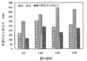
- the shear stress generated on the screw surface can be calculated as follows.
- the shear force ⁇ i generated on the surface of the screw can be calculated as in Equation 1. That is, the radius of the implant screw (half the diameter of the outer circumference) is r , the area where the screw is in contact with the alveolar bone is Ai, and the torque at the time of implantation is T, which can be expressed approximately as in Equation 1. ..
- the pressure and shear stress generated on the screw surface during implantation are concentrated near the tip of the screw thread. Also, when implanting the screw, high pressure and shear force are generated mainly in the area of hard cortical bone. Since the average thickness of cortical bone is about 1.0 to 1.5 mm and the pitch of the screw is 1 to 2 mm, the screw is screwed in with the shearing force concentrated on almost one circumference of the thread. Will be. Assuming that the width of the tip of the screw thread is h, the area Ai of the tip of the screw thread where the shear stress is the highest is as shown in Equation 2.
- the minimum implantation torque T for promoting bone formation is 40 Ncm (Non-Patent Document 3), the radius r of the implant screw is 2 mm, and the width of the tip of the screw thread is 0.2 mm, which are substituted into equations 1 and 2.
- the shear stress ⁇ i generated on the surface is obtained.
- the shear stress ⁇ i generated on the surface is similarly about 160 MPa.
- the shape of the tip of the screw thread is 80 to 160 MPa, and the shearing force increases as the tip of the screw thread becomes sharper.
- the adhesion force at the interface between the film and the substrate should be larger than the shear force ⁇ i on this surface.
- the shear stress ⁇ c at the interface between the membrane and the substrate for satisfying the embedding torque is preferably 80 MPa or more, preferably 160 MPa or more.
- the thickness of the film of the biocompatible material of the present application is not particularly limited as long as it has any one or two or all of the above-mentioned properties i) to iii), or the above-mentioned surface roughness or a difference thereof.
- the average thickness is preferably 0.10 to 30 ⁇ m.
- the average thickness of the film corresponding to the contact portion with the bone and its vicinity is preferably 0.10 to 30 ⁇ m, preferably 0.20 to 20 ⁇ m, and more preferably 0.40 to 15 ⁇ m.
- the biocompatible material of the present invention may have the membrane essentially made of magnesium alone. Further, in one aspect, it is preferable that the film is composed only of magnesium.
- the membrane comprises magnesium and calcium, and the membrane has calcium exceeding 0% by weight and 40% by weight, assuming that the total weight of magnesium and calcium is 100% by weight. % Or less, preferably 0.8 to 35% by weight, more preferably 5 to 30% by weight, and most preferably 15 to 25% by weight.
- the membrane may contain biocompatible materials in addition to magnesium and calcium. Biocompatible materials can include, but are not limited to, for example, zinc, phosphorus, and the like.
- the amount of zinc is to eliminate the membrane after implantation, assuming that the total weight of magnesium, calcium and zinc is 100% by weight. It is preferably 10% by weight or less.
- the film when the film has magnesium and calcium in one aspect, it is preferable that the film is Mg 2 Ca free.
- Mg 2 Ca-free means that a peak based on Mg 2 Ca is not observed in the X-ray diffraction analysis, and preferably the diffraction peak generated from each of the crystals of the substrate and Mg 2 Ca is heavy. No peak based on Mg 2 Ca is observed at the diffraction angle (the respective diffraction peaks are separated by 1 ° or more in X-ray analysis using a cobalt (Co) tube), for example, X-ray using a Co tube. It is good that no peak is observed in the range of 36 to 37 ° in the analysis.
- the film has an amorphous portion in one aspect.
- the film may be essentially made of amorphous material, and preferably made of only amorphous material.
- amorphous means that no sharp peak is observed in the X-ray diffraction analysis.
- the membrane is essentially composed of only magnesium and calcium. Further, in this application, it is preferable that the membrane is composed of only magnesium and calcium in one aspect.
- the biocompatible material of the present invention preferably has a biocompatible substrate in addition to the film having the above characteristics.
- the biocompatible substrate is not particularly limited as long as it has the above-mentioned "biocompatibility", and examples thereof include, but are not limited to, pure titanium, titanium alloy, cobalt-chromium alloy, stainless steel, and zirconia. .. Further, examples of the biocompatible substrate include, but are not limited to, alumina, calcium phosphate, magnesia and the like.
- the biocompatible substrate is preferably pure titanium, a titanium alloy and zirconia, more preferably ceramics, and even more preferably zirconia.
- biocompatible material of the present invention may have other layers in addition to the above-mentioned biocompatible substrate and the above-mentioned film.
- one or more layers may be provided between the biocompatible substrate and the membrane.
- one or more layers may be provided on the upper part of the above-mentioned film, that is, on the side opposite to the substrate.
- the shape of the biocompatible material of the present invention is not particularly limited, but for example, a columnar shape, a cylindrical shape, a conical trapezoidal shape and a conical shape, and a shape or a rectangular parallelepiped having a screw-shaped threaded portion as part of the shape. It is preferable to be one selected from the group consisting of a cube, a block shape such as a rectangular parallelepiped and a cube having a partially inclined surface, and a wedge shape.
- the field of application of the biocompatible material of the present invention is not particularly limited, and for example, artificial bone material, intraosseous fixation device material, dental implant material, orthodontic anchor screw material, intramedullary nail material, and vertebrae. It should be one selected from the group consisting of interbody-fixing materials. Examples include, but are not limited to, artificial bones, pins, wires, bolts, screws, washers, intramedullary nails, vertebral body spacers and the like.
- the biocompatible material of the present invention can be produced, for example, by the following method. That is, (A) Step of preparing a biocompatible substrate; (B) A step of preparing a sputter target having magnesium and optionally calcium; (C) A step of cleaning the surface of the biocompatible substrate in a vacuum; (D) Using the sputtering target, the temperature of the biocompatibility substrate obtained in the step (C) is set to 130 ° C. or lower, preferably 90 ° C. or lower, more preferably 60 ° C. or lower, and the biocompatibility by sputtering. A step of forming a film having magnesium and optionally calcium on the surface of the substrate; The biocompatible material can be obtained by having the above-mentioned biocompatible material.
- Step (A) is a step of preparing a biocompatible substrate.
- the above-mentioned “biocompatible substrate” may be commercially purchased, or the commercially purchased one may have a desired shape. In addition, it may have a step of grinding and / or polishing the surface of the purchased product or the obtained shape.
- the grinding method and the polishing method conventionally known methods can be used.
- Step (B) is a step of preparing a sputter target having magnesium and optionally calcium. Depending on the membrane having the desired composition, it is advisable to prepare the sputter target. For example, a predetermined metal may be melted at a predetermined ratio to produce the product.
- the bias is appropriately adjusted, and argon ions or the like are made to collide with the surface of the substrate to remove impurities on the surface at the atomic level. This is the process of removing and cleaning. By appropriately performing this, the adhesion of the film can be stabilized and the surface of the substrate can be activated.
- the temperature of the biocompatible substrate is set to 130 ° C. or lower, preferably 90 ° C. or lower, more preferably 60 ° C. or lower by using a sputtering target, and magnesium and magnesium are added to the surface of the biocompatible substrate by sputtering.
- This is a step of forming a film having calcium arbitrarily.
- the sputtering apparatus it is preferable to use a magnetron sputtering apparatus.
- a strong magnet magnet
- the sputter particles metal particles generated by colliding argon ions with the target are efficiently deposited on the substrate using a magnetic field. be able to.
- the target film can be formed at a constant film formation rate.
- the magnesium-based metal film has a coefficient of linear expansion three times or more larger than that of the substrate zirconium, titanium, and titanium alloy, when the sputtering temperature is high, the temperature difference from the room temperature near the room temperature where the implant is used becomes large. Tension stress (thermal stress) is generated at the interface on the film side, and the film is easily peeled off. Therefore, in order to prevent the film from peeling off after film formation and to prevent harmful stress from remaining during implant placement, the temperature of the substrate in sputtering is kept below a certain temperature, that is, at 130 ° C. or lower, preferably 90 ° C. or lower. By controlling the temperature to 60 ° C. or lower, a film having high adhesion can be formed.
- the above temperature can be estimated by calculating the thermal stress as follows. That is, the stress (thermal stress) at the interface generated when the temperature is lowered from the sputtering temperature to room temperature can be expressed by about Equation 4.
- ⁇ T the temperature difference between the substrate temperature Td and the room temperature Tr during sputtering
- ⁇ 1 the average linear expansion coefficient of the substrate between the temperatures Tr and Td
- ⁇ 2 the coating between the temperatures Tr and Td.
- E 1 the average elastic coefficient of the substrate between the temperatures Tr and Td
- E 2 the average elastic coefficient of the film between the temperatures Tr and Td.
- the substrate is zirconia
- the coating film is pure magnesium
- the coefficient of linear expansion is 8 ⁇ 10 -6 and 25 ⁇ 10 -6
- the elastic modulus is 210 GPa and 40 GPa, respectively.
- the proof stress of pure magnesium is generally said to be about 90 to 100 MPa
- the shear yield strength is about 50 MPa.
- the film formation temperature should be 130 ° C or lower, and the film formation should be performed at a safety factor of 90 ° C or less, which is twice as high, and 60 ° C or less when considering the safety factor of about three times. Is preferable.
- the production method of the present invention may have steps other than the above (A) to (D).
- steps other than the above (A) to (D) For example, as described above, after the step (A) and before the step (B), there may be a step of forming the "biocompatible substrate" into a desired shape, and a step of grinding and / or polishing the surface of the shape. ..
- a step of forming the "biocompatible substrate" into a desired shape for example, after a layer is provided between the substrate and the film, it is preferable to provide the step of providing the layer after the step (A) and before the step (D).
- the present invention will be specifically described with reference to Examples, but the present invention is not limited to these Examples.
- ⁇ Base material> As the substrate material assuming an implant, plate-shaped pure titanium A1 and zirconia A2, which were cut into a thickness of 3 mm and cut into a size of 10 ⁇ 10 mm and subjected to a general grinding process in a predetermined direction on one plane, were used. A glass substrate AC1 having a thickness of 1.2 mm and a thickness of 26 ⁇ 76 mm was also used in order to investigate the details of the characteristics of the formed film.
- pure titanium B1 and zirconia B2 having a columnar shape ( ⁇ 4 mm, length 10 mm) similar to the shape of an actual tooth root implant were used.
- a part of the surface was masked in order to measure the thickness of the film to be formed.
- a magnetron sputtering device was used as the sputtering device.
- As the sputter target four types of ingots produced by dissolving pure magnesium and pure magnesium and pure calcium in a predetermined ratio were machined into a disk shape having a diameter of about 120 mm.
- the four types of ingots had a calcium content of 0%, 10%, 20% or 30%, and the remaining amount was magnesium.
- % of the amount of calcium is the ratio of the weight of calcium when the total of the weight of calcium and the weight of magnesium is 100% by weight, and is represented by the following weight%.
- Calcium weight% Calcium weight / (magnesium weight + calcium weight) x 100
- the substrate was placed on the stage of the sputtering apparatus so as to face the sputtering target.
- the columnar substrate was arranged so that the bottom surface of the cylinder was on the top and bottom, and the plate-shaped substrate was arranged so that the ground surface was on the top surface.
- the pressure was first reduced to a predetermined value, harmful gas in the chamber was removed, and then argon gas was sealed.
- the surface of the sputter target and substrate is ion-cleaned to remove surface oxides and harmful compound layers at the interface between the substrate and the membrane. While removing impurities that reduce adhesion, it formed an active surface that is advantageous for bone formation.
- the temperature of the substrate was kept at room temperature, the pressure of argon was 1 to 10 mTorr, the sputter voltage and the bias of the substrate were adjusted, and the film formation process (deposition) for 12 hours was performed.
- the thickness of the obtained film was measured as follows. That is, the thickness of the film was measured by actually measuring the step between the formed portion on the substrate and the portion not formed with the above-mentioned masking by the stylus method.
- the components of each film were measured with an energy dispersive X-ray analyzer (EDX).
- Table 1 shows the calcium weight% of the target, the type of the substrate, the Ca amount (% by weight) as a result of EDX, and the film thickness ( ⁇ m) obtained by the stylus method.
- the amount of Ca (% by weight) based on the EDX results for the columnar sample was not measured because it is considered to be equivalent to that of the plate-shaped sample.
- the arithmetic mean height Ra1 of the line roughness of the surface was measured.
- the arithmetic average height Ra2 of the line roughness of the surface before film formation was measured.
- A1-C0, A1-C10, A1-C20 and A1-C30, and about A2-C0, A2-C10, A2-C20 and A2-C30 formed by using a plate-shaped substrate using zirconia.
- the film after the film formation was removed by immersing it in a 5% aqueous hydrochloric acid solution for about 10 seconds.
- the arithmetic mean height Ra2'of the line roughness of the surface from which the film of the obtained sample was removed was measured. As will be described later, it was confirmed that Ra2 and Ra2'are almost the same.
- the arithmetic mean height of the line roughness was measured by moving the stylus in the directions parallel and perpendicular to the grinding marks.
- the measurement was performed in accordance with JIS B0601: 2013 with a contact type surface roughness measuring device (SV-3000, manufactured by Mitutoyo Co., Ltd.).
- SV-3000 contact type surface roughness measuring device
- the sample was contacted with a static measuring force of 0.75 mN for measurement. ..
- 0.02 ⁇ Ra ( ⁇ m) ⁇ 0.1 As a result of the preliminary measurement, 0.02 ⁇ Ra ( ⁇ m) ⁇ 0.1, so this measurement was carried out with a reference length of 0.8 ⁇ m, an evaluation length of 4 mm, a cutoff of ⁇ c of 0.8 mm, and ⁇ s of 2.5 ⁇ m.
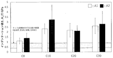
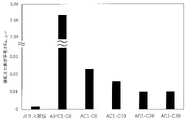
- FIG. 3 is a diagram showing the measurement results of the arithmetic mean surface roughness of A1-C0, A1-C10, A1-C20 and A1-C30 formed by forming a film using a plate-shaped substrate using titanium.
- the value with diagonal lines is the value of Ra1
- the value without diagonal lines is the value of Ra2.
- FIG. 4 shows the results of a sample formed by using a plate-shaped substrate using “zirconia” instead of “titanium” in FIG. 3, and as in FIG. 3, the value with diagonal lines is the value of Ra1. No diagonal line is the value of Ra2.
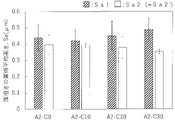
- Table 2 summarizes the values of Ra1 (values with diagonal lines in FIGS. 3 and 4) for each sample.
- Table 3 summarizes the differences between the Ra1 value (value with diagonal lines in FIGS. 3 and 4) and the Ra2 value (value without diagonal lines in FIGS. 3 and 4) for each sample. Is.
- the arithmetic mean height Sa1 of the surface roughness of the surface was measured.
- the arithmetic average height Sa2 of the surface roughness of the surface before film formation was measured.
- A1-C0, A1-C10, A1-C20 and A1-C30, and about A2-C0, A2-C10, A2-C20 and A2-C30 formed by using a plate-shaped substrate using zirconia.
- the film after the film formation was removed by immersing it in a 5% aqueous hydrochloric acid solution for about 10 seconds.
- the arithmetic mean height Sa2'of the surface roughness of the surface from which the film of the obtained sample was removed was measured. As will be described later, it was confirmed that Sa2 and Sa2'are almost the same.
- the arithmetic mean height of the surface roughness was measured by scanning the measuring probe in the direction perpendicular to the grinding mark. The measurement was performed in accordance with ISO25178 with a laser probe type non-contact 3D measuring device (NH-3SP, manufactured by Mitaka Kohki Co., Ltd.). Using a laser with a probe diameter of 1 ⁇ m, a range of 100 ⁇ m ⁇ 100 ⁇ m was measured at a measurement pitch of 1 ⁇ m. The arithmetic mean height of the surface roughness was performed using the analysis software TaryMapGold (version 7, manufactured by Taylor Hobson).
- the arithmetic mean height was calculated after performing shape removal by a quadratic polynomial on the calibration surface leveled by the least squares method, without using a filter for separating the wavelength component of the contour curve.
- the arithmetic mean roughness of the surface having no film was measured with respect to a) the measured value Sa2 before the film formation and b) the measured value Sa2'of the surface removed after the film formation. As a result, although not shown, it was confirmed that the results were almost the same. From this result, it was confirmed that b) the removal method after film formation was appropriate.
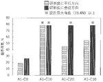
- FIG. 5 is a diagram showing measurement results of arithmetic mean surface roughness for A1-C0, A1-C10, A1-C20 and A1-C30 formed by forming a film using a plate-shaped substrate using titanium.
- the value with diagonal lines is the value of Sa1
- the value without diagonal lines is the value of Sa2.
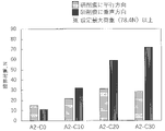
- FIG. 6 shows the results of a sample formed by using a plate-shaped substrate using “zirconia” instead of “titanium” in FIG. 5, and as in FIG. 5, the value of Sa1 with diagonal lines is shown. No diagonal line is the value of Sa2.
- Table 4 summarizes the values of Sa1 (values with diagonal lines in FIGS. 5 and 6) for each sample.
- Table 5 summarizes the differences between the Sa1 value (value with diagonal lines in FIGS. 5 and 6) and the Sa2 value (value without diagonal lines in FIGS. 5 and 6) for each sample. Is.
- FIGS. 3 and 4 From FIGS. 3 and 4, FIGS. 5 and 6, Tables 2 and 3, and Tables 4 and 5, the following can be seen. That is, in the implantation of implant materials for tooth roots, for example, it is important to have a relatively smooth surface roughness in reducing the burden on the patient and in proper implantation and tightening, which is the arithmetic of the line roughness of the sample. It depends on the maximum value of the average surface height and the arithmetic average surface height of the surface roughness. From Tables 2 and 4 above, in this example, the maximum value of the arithmetic mean surface height of line roughness or surface roughness is 1 ⁇ m or less. Therefore, the sample obtained in this example is embedded. It can be done smoothly.
- a general grounded substrate is used, but as will be described later in the comparative example, it is possible to obtain a smoother surface roughness by applying a smoother substrate. ..
- a substrate is a screw (bone screw or anchor screw) that is premised on removal, shortening the period until secondary fixing after implantation, and suppressing physical engagement due to unevenness on the surface of the substrate at the time of removal. It enables smooth removal.
- the difference value between Ra1 and Ra2 (Ra1-Ra2) (nm) of each sample and the difference value between Sa1 and Sa2 (Sa1-Sa2) (nm). ) Can be a relatively small value.
- the maximum value of the surface roughness of the film itself is 30 nm or less, the surface roughness is hardly increased by forming the film.
- reducing the difference indicates that the film is not locally formed and evenly covers the surface of the substrate to form a film, and the effect of the film is stable in every corner of the substrate. It can be expected to be demonstrated.
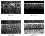
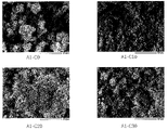
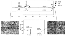
- FIG. 7 shows scanning electron microscope images (SEM images) in the cross-sectional direction of the film for AC1-C0, AC1-C10, AC1-C20 and AC1-C30 formed by using a glass substrate.
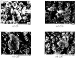
- FIG. 8 shows a scanning electron microscope image of a surface having a film for A1-C0, A1-C10, A1-C20 and A1-C30 formed by using a plate-shaped substrate made of titanium.
- FIG. 9 shows a scanning electron microscope image of a surface having a film for A2-C0, A2-C10, A2-C20 and A2-C30 formed by using a plate-shaped substrate using zirconia.
- HCP hexagonal dense structure
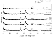
- ⁇ X-ray diffraction analysis> The obtained sample, AC1-C0, AC1-C10, AC1-C20 and AC1-C30 films formed using a glass substrate, and A1-C0, A1- formed using a plate-shaped substrate using titanium.
- X-ray diffraction analysis was performed on C10, A1-C20 and A1-C30, and A2-C0, A2-C10, A2-C20 and A2-C30 formed by using a plate-shaped substrate using zirconia.
- As the scratch test apparatus a Scratch tester CSR1000 (manufactured by Reska Co., Ltd.) was used, and a rockwell indenter having a diameter of 0.8 mm was used to apply a load in the range of 0 to 8 kg weight. The sample after the scratch test was observed by SEM / EDX, and the distance from the initial position of the scratch test to the exposed position of the substrate was measured to determine the critical load.
- FIG. 14 shows the appearance of A1-C0, A1-C10, A1-C20, and A1-C30 formed by using a plate-shaped substrate made of titanium near the critical load after the scratch test in the direction parallel to the grinding mark. It is an SEM image.
- FIG. 15 shows the appearance of A2-C0, A2-C10, A2-C20, and A2-C30 formed by using a plate-shaped substrate using zirconia near the critical load after the scratch test in the direction parallel to the grinding mark. It is an SEM image. From FIGS. 14 and 15, it was found that in all the films, no partial peeling of the films was observed and the "adhesion" was good. From this, it was found that the wear resistance of the film can be sufficiently exhibited when a force is applied to the surface.
- FIGS. 14 and 15 show that no flake-like fracture or cracks during deformation were observed in all the films tested, and the films showed sufficient "ductility" and were not brittle. I understand.
- FIG. 16 shows that the indenter is almost up to the substrate in a scratch test in the direction parallel to or perpendicular to the grinding marks of A1-C0, A1-C10, A1-C20 and A1-C30 formed by forming a film using a plate-shaped substrate using titanium. It is a measurement result for finding the load when it reaches, that is, the critical load of the membrane.
- FIG. 17 shows the indenter almost up to the substrate in a scratch test in the direction parallel to or perpendicular to the grinding marks of A2-C0, A2-C10, A2-C20 and A2-C30 formed by using a plate-shaped substrate using zirconia. It is a measurement result for finding the load when it reaches, that is, the critical load of the membrane. The critical load also indicates the degree of adhesion of the film.
- A1-C0, A1-C10, A1-C20 and A1-C30 formed using a plate-shaped substrate using titanium, A2-C0, A2-C10 formed using a plate-shaped substrate using zirconia, Of A2-C20 and A2-C30, A1-C10 in the scratch test in the direction parallel to the grinding mark and A1-C10, A1-C20, A1-C30 in the scratch test in the direction perpendicular to the grinding mark have a critical load of 78.4N or more. It turns out that it is excellent. Even A2-C0, which has the smallest critical load, is about 10N, which satisfies the critical load of 10N or more.
- a critical load of about 10 N corresponds to an implant torque of 150 N cm that can be implanted without peeling of the membrane in an implant screw having a screw radius of 2 mm and a thread tip width of 0.2 mm.
- the 150 Ncm has a safety factor about 4 times stronger than the implantation torque of 35 to 45 N cm required for the implant, and it can be seen that the membrane of this example has the desired adhesion.
- the critical shear stress at the interface can be determined using the results of the scratch test.
- a load W is applied to the surface of the film through an indenter, and the tip of the indenter is dragged (skidned) in parallel with the film to measure the length until the film is peeled off and the surface of the substrate is exposed. Since the indenter load is set to be proportional to the drag length, the critical load Wc when the film is peeled off can be known from this length.
- the critical load Wc when the film is peeled off can be known from this length.
- the brittleness and ductility of the membrane can be understood. Here, it is calculated using the commonly used Benjamine-Weaver formula.
- Equation 5 the shear stress at the interface at this time is ⁇ c (critical shear). Stress
- the tip R of the diamond indenter was 0.8 mm, the Brinell hardness of the titanium substrate and the zirconia substrate was 2.3 GPa and 12.0 GPa, respectively, and the critical load was calculated using the scratch test values of FIGS. 16 and 17. .. Since the hardness of Brinell is not shown in the conversion table at 10 GPa or more, the value of zirconia is almost the same as that of Brinell, and the value of Vickers using diamond as an indenter is used. For the critical load, the result of the scratch test in the direction of taking a small value (direction parallel to the grinding mark) was used.
- the shear stress ⁇ c at the interface greatly exceeded 80 MPa and exceeded 160 MPa. From this, it was found that the shear stress at the interface of the film produced by the present invention satisfies Equation 3, has sufficiently stronger adhesion than the shear stress generated in the outer peripheral portion at the time of embedding, and does not peel off at the time of embedding. rice field.
- FIG. 18 shows the yield shear stresses of A1-C0 to C30 and A2-C0 to C30 converted from the hardness of the films of A1-C0 to C30 and A2-C0 to C30.
- the calculation method of the yield shear stress can be found in, for example, G. E. Dieter: Mechanical metallurgy, McGraw-Hill, 1988.
- the yield stress of the film is smaller than the shear stress at the interface of the film, and when a shear force is applied to the surface, the film is deformed ductilely before the interface and does not peel off from the interface of the film. I understand. This was reflected in the appearance of the scratch test in FIGS. 14 and 15.
- the membrane of the present invention formed on the implant screw has sufficient wear resistance, adhesion and ductility based on the results of the ⁇ hardness test> and the ⁇ scratch test>, and has been used as the membrane of the implant screw so far. It was found to have no excellent membrane properties.
- HBSS (+) solution containing calcium and magnesium was used as the simulated body fluid.
- HBSS (+) solution containing calcium and magnesium was used as the simulated body fluid.
- each sample was immersed in 400 ml of simulated body fluid, kept in a constant temperature bath at 37 ° C. for 1 week, and then the sample was taken out from the solution. Further, in order to bring the equilibrium pH in the solution closer to the in vivo environment, the amount of the HBSS (+) solution was adjusted so that the equilibrium pH after elution of the sputtering film was 8.0 or less. For comparison, each substrate without a membrane was also tested.
- FIG. 20 SEM of a film newly formed on the substrate by immersing A1-C0, A1-C10, A1-C20 and A1-C30 formed on a plate-shaped substrate using titanium in HBSS for one week. Show the image.
- FIG. 21 SEM of a film newly formed on the substrate by immersing A2-C0, A2-C10, A2-C20 and A2-C30 formed on a plate-shaped substrate using zirconia in HBSS for one week. Show the image.
- Table 7 shows the results of component analysis performed by fluorescent X-rays at substantially the center of the SEM image (specifically, the position of “+” in the SEM image).
- the ratio of calcium to phosphorus which is an indicator of the presence of apatite, shows a value of 1.5 to 2.0 in all sputtering membranes, and it is highly possible that apatite is formed as a component. I understand. Further, in order to analyze the structure of the film, X-ray diffraction (XRD) analysis was performed by a thin film method in which the X-ray incident angle was fixed and only the detector was scanned. The results are shown in FIGS. 22 and 23. Peaks appeared on most substrates sputtered at diffraction angles that represent the characteristics of apatite on both titanium and zirconia substrates.
- XRD X-ray diffraction
- A2-C0 the peak of apatite was not confirmed, but apatite was present on the surface as shown in FIGS. 21 and 7. From this, it can be seen that the amount of apatite formed in A2-C0 is smaller than that of the sample having another sputtering film. As described above, it was confirmed from the component analysis and the structural analysis that apatite was formed on all the substrates having the sputtering film. It was also confirmed that the amount of apatite formed was increased by containing calcium in the sputtering film.
- FIG. 25 shows a comparison of the XRD and scratch test results of A2-C20 formed into a film using a plate-shaped substrate using zirconia and A2-C20-H heat-treated thereof.
- the heat treatment was carried out in a vacuum at 200 ° C. for 1 hour and then cooled in a furnace. From the XRD results, it can be seen that A2-C20 is amorphous and has a structure free of Mg 2 Ca, and A2-C20-H has a structure in which magnesium crystals and Mg 2 Ca are mixed.
- A2-C20 which is amorphous and has a structure free of Mg 2 Ca, has a critical load of about 30 N
- A2-C20-H which has a structure in which magnesium crystals and Mg 2 Ca are mixed, has a critical load. : It was about 2.7N.
- looking at the photograph after the scratch test of A2-C20 no crack or partial peeling was observed.
- looking at the photograph of A2-C20-H after the scratch test many cracks and partial peeling are observed. From these facts, it can be seen that the amorphous and Mg 2 Ca-free structure has non-brittle properties and exhibits a high critical load.
- Mg 2 Ca is present and brittle, it can be seen that the critical load is significantly low.
- Table 8 shows a comparison of the adhesion strength between the film of the prior art and the film of the present application.
- the adhesion strength of the calcium titanate film described in Patent Document 2 is 4.9 MPa
- the adhesion strength of the calcium phosphate coating film described in Non-Patent Document 2 is 80 MPa.
- These are the tensile strengths obtained in the pin tensile test using the adhesive.
- the tensile strength of the film of the present application was measured by a similar pin tensile test, but the tensile strength was so strong that the adhesive broke first, and it was impossible to measure.
- a scratch test or the like capable of measuring a stronger adhesion strength is generally used.
- both the tensile strength and the shear strength of the membrane are 20 MPa or more. Therefore, the shear stress calculated in this example and the tensile strength in the prior art can be compared as the adhesion strength at the same level. Therefore, it can be seen that even the lowest adhesion strength of A2-C20 calculated in this example: 170 MPa is extremely high as compared with the prior art.
Abstract
Description
また、本発明は、該生体適合性材料の製造方法に関する。
歯根用インプラントの材料としては、比較的生体に悪影響を与えない金属チタン、チタン合金、またはセラミックスのジルコニアが使われている。
特許文献5は、歯根用インプラントにおいて、基材の活性面を活かすために、プロテクト膜でインプラントを覆って保護することを開示している。このプロテクト膜は、審美性を保つ目的で埋入後に消失するように作られているが、この膜自身に骨形成を促進する成分や機能はない。
また、本発明の目的は、上記目的の他に、又は上記目的に加えて、適切な埋入トルクでの埋入又は締め込みに適する、比較的滑らかな表面粗さを有する膜を有する生体適合性材料を提供することにある。
また、本発明の目的は、上記目的の他に、又は上記目的に加えて、上記生体適合性材料の製造方法を提供することにある。
<A1> マグネシウム及び任意にカルシウムを有してなる膜を有する生体適合性材料であって、前記膜は、マグネシウムとカルシウムとの合計の重量を100重量%とすると、カルシウムが0~40重量%有し、前記膜の面粗さの算術平均高さSa1が2μm以下、好ましくは1μm以下である、上記生体適合性材料。
<A3> 上記<A2>において、前記膜の面粗さの算術平均高さSa1が2μm以下、好ましくは1μm以下であるのがよい。
i)インデンテーション試験により得られる硬度が0.4GPa以上、好ましくは0.9GPa以上、より好ましくは1.2GPa以上である。
ii)臨界荷重Wc(N)と膜厚t(μm)との関係Wc/tが、1N/μm以上、より好ましくは2N/μm以上である。
iii)膜と基体の界面の臨界せん断応力が80MPa以上、好ましくは160MPa以上である。
a)前記膜の面粗さの算術平均高さSa1が2μm以下、好ましくは1μm以下であるか、及び/又は
b)前記膜の面粗さの算術平均高さSa1と前記膜を有しない表面の面粗さの算術平均高さSa2との差分が300nm以下、好ましくは200nm以下、より好ましくは150nm以下である、のがよい。
<A6> 上記<A1>~<A5>のいずれかにおいて、前記膜の平均厚さが0.10~30μmであるのがよい。特に、骨との接触部およびその近傍に相当する前記膜の平均厚さが0.10~30μm、好ましくは0.20~20μm、より好ましくは0.40~15μmであるのがよい。
<A8> 上記<A1>~<A6>において、前記膜が、マグネシウムのみからなるのがよい。
<A10> 上記<A9>において、前記膜が、マグネシウム及びカルシウムのみから本質的になるのがよい。
<A11> 上記<A9>において、前記膜が、マグネシウム及びカルシウムのみからなるのがよい。
<A13> 上記<A9>~<A12>のいずれかにおいて、前記膜が非晶質部分を有するのがよい。
<A14> 上記<A9>~<A12>のいずれかにおいて、前記膜が非晶質から本質的になるのがよく、好ましくは非晶質のみからなるのがよい。
<A17> 上記<A1>~<A16>のいずれかにおいて、前記生体適合性材料の形状が、円筒状、円錐台状及び円錐状、並びに該形状の一部にスクリュー状のねじ部を備えた形状、直方体及び立方体、並びに一部傾斜面を有する直方体及び立方体等のブロック形状、及びくさび形状からなる群から選ばれる1種であるのがよい。
(B)マグネシウム及び任意にカルシウムを有してなるスパッタターゲットを準備する工程;
(C)前記生体適合性基体の表面を真空中でクリーニングする工程;及び
(D)前記スパッタターゲットを用いて、前記(C)工程で得られた生体適合性基体の温度を130℃以下、好ましくは90℃以下、より好ましくは60℃以下として、スパッタリングにより前記生体適合性基体にマグネシウム及び任意にカルシウムを有してなる膜を形成する工程;
を有することにより、マグネシウム及び任意にカルシウムを有してなる膜を有する生体適合性材料であって、前記膜は、マグネシウムとカルシウムとの合計の重量を100重量%とすると、カルシウムが0~40重量%有する生体適合性材料を得る、生体適合性材料の製造方法。
a)前記膜の面粗さの算術平均高さSa1が2μm以下、好ましくは1μm以下、であるか、及び/又は
b)前記膜の面粗さの算術平均高さSa1と前記膜を有しない表面の面粗さの算術平均高さSa2との差分が300nm以下、好ましくは200nm以下、より好ましくは150nm以下である、のがよい。
<A20> 上記<A18>又は<A19>において、前記膜は、下記i)~iii)のうちいずれか一つ、又は二つ、又は全て、の特性を有するのがよい:
i)インデンテーション試験により得られる硬度が0.4GPa以上、好ましくは0.9GPa以上、より好ましくは1.2GPa以上である。
ii)臨界荷重Wc(N)と膜厚t(μm)との関係Wc/tが、1N/μm以上、より好ましくは2N/μm以上である。
iii)膜と基体の界面の臨界せん断応力が80MPa以上、好ましくは160MPa以上である。
<B3> 上記<B2>において、前記膜の線粗さの算術平均高さRa1が2μm以下、好ましくは1μm以B下であるのがよい。
i)インデンテーション試験により得られる硬度が0.4GPa以上、好ましくは0.9GPa以上、より好ましくは1.2GPa以上である。
ii)臨界荷重Wc(N)と膜厚t(μm)との関係Wc/tが、1N/μm以上、より好ましくは2N/μm以上である。
iii)膜と基体の界面の臨界せん断応力が80MPa以上、好ましくは160MPa以上である。
c)前記膜の面粗さの算術平均高さSa1が2μm以下、好ましくは1μm以下であるか、及び/又は
d)前記膜の面粗さの算術平均高さSa1と前記膜を有しない表面の面粗さの算術平均高さSa2との差分が300nm以下、好ましくは200nm以下、より好ましくは150nm以下である、のがよい。
<B6> 上記<B1>~<B5>のいずれかにおいて、前記膜の平均厚さが0.10~30μmであるのがよい。特に、骨との接触部およびその近傍に相当する前記膜の平均厚さが0.10~30μm、好ましくは0.20~20μm、より好ましくは0.40~15μmであるのがよい。
<B8> 上記<B1>~<B6>において、前記膜が、マグネシウムのみからなるのがよい。
<B10> 上記<B9>において、前記膜が、マグネシウム及びカルシウムのみから本質的になるのがよい。
<B11> 上記<B9>において、前記膜が、マグネシウム及びカルシウムのみからなるのがよい。
<B13> 上記<B9>~<B12>のいずれかにおいて、前記膜が非晶質部分を有するのがよい。
<B14> 上記<B9>~<B12>のいずれかにおいて、前記膜が非晶質から本質的になるのがよく、好ましくは非晶質のみからなるのがよい。
<B17> 上記<B1>~<B16>のいずれかにおいて、前記生体適合性材料の形状が、円筒状、円錐台状及び円錐状、並びに該形状の一部にスクリュー状のねじ部を備えた形状、直方体及び立方体、並びに一部傾斜面を有する直方体及び立方体等のブロック形状、及びくさび形状からなる群から選ばれる1種であるのがよい。
(B)マグネシウム及び任意にカルシウムを有してなるスパッタターゲットを準備する工程;
(C)前記生体適合性基体の表面を真空中でクリーニングする工程;及び
(D)前記スパッタターゲットを用いて、前記(C)工程で得られた生体適合性基体の温度を130℃以下、好ましくは90℃以下、より好ましくは60℃以下として、スパッタリングにより前記生体適合性基体にマグネシウム及び任意にカルシウムを有してなる膜を形成する工程;
を有することにより、マグネシウム及び任意にカルシウムを有してなる膜を有する生体適合性材料であって、前記膜は、マグネシウムとカルシウムとの合計の重量を100重量%とすると、カルシウムが0~40重量%有し、
a)前記膜の線粗さの算術平均高さRa1が2μm以下、好ましくは1μm以下、であるか、及び/又は
b)前記膜の線粗さの算術平均高さRa1と前記膜を有しない表面の線粗さの算術平均高さRa2との差分が300nm以下、好ましくは200nm以下、より好ましくは150nm以下である生体適合性材料を得る、生体適合性材料の製造方法。
c)前記膜の面粗さの算術平均高さSa1が2μm以下、好ましくは1μm以下、であるか、及び/又は
d)前記膜の面粗さの算術平均高さSa1と前記膜を有しない表面の面粗さの算術平均高さSa2との差分が300nm以下、好ましくは200nm以下、より好ましくは150nm以下である、のがよい。
<B20> 上記<B18>又は<B19>において、前記膜は、下記i)~iii)のうちいずれか一つ、又は二つ、又は全て、の特性を有するのがよい:
i)インデンテーション試験により得られる硬度が0.4GPa以上、好ましくは0.9GPa以上、より好ましくは1.2GPa以上である。
ii)臨界荷重Wc(N)と膜厚t(μm)との関係Wc/tが、1N/μm以上、より好ましくは2N/μm以上である。
iii)膜と基体の界面の臨界せん断応力が80MPa以上、好ましくは160MPa以上である。
また、本発明により、上記効果の他に、又は上記効果に加えて、適切な埋入トルクでの埋入又は締め込みに適する、比較的滑らかな表面粗さを有する膜を有する生体適合性材料を提供することができる。
また、本発明により、上記効果の他に、又は上記効果に加えて、上記生体適合性材料の製造方法を提供することができる。
本願は、マグネシウム及び任意にカルシウムを有してなる膜を有する生体適合性材料であって、該膜は、マグネシウムとカルシウムとの合計の重量を100重量%とすると、カルシウムが0~40重量%、カルシウムを有する場合には、該カルシウムの量が0重量%を越えて40重量%以下、好ましくは0.8~35重量%、より好ましくは5~30重量%、最も好ましくは15~25重量%有する生体適合性材料を提供する。
また、カルシウムの量は、より好ましくは5~35重量%、更に好ましくは15~35重量%、最も好ましくは25~35重量%有するのがよい。
また、本発明は、他の面において、b)該膜の線粗さの算術平均高さRa1と該膜を有しない表面の線粗さの算術平均高さRa2との差分が300nm以下、好ましくは200nm以下、より好ましくは150nm以下である生体適合性材料を提供する。
さらに、本発明は、ある面において、c)該膜の面粗さの算術平均高さSa1が2μm以下、好ましくは1μm以下である生体適合性材料を提供する。
また、本発明は、他の面において、d)該膜の面粗さの算術平均高さSa1と該膜を有しない表面の面粗さの算術平均高さSa2との差分が300nm以下、好ましくは200nm以下、より好ましくは150nm以下である生体適合性材料を提供する。
なお、生体適合性材料は、上記a)及び/又はb)の特性と上記c)及び/又はd)の特性とを有してもよい。
i)インデンテーション試験により得られる硬度が0.4GPa以上、好ましくは0.9GPa以上、より好ましくは1.2GPa以上である。
ii)臨界荷重Wc(N)と膜厚t(μm)との関係Wc/tが、1N/μm以上、より好ましくは2N/μm以上である。
iii)膜と基体の界面の臨界せん断応力が80MPa以上、好ましくは160MPa以上である。
<膜>
本発明の生体適合性材料は、上述の特性a)及び/又はb)、具体的には所定の線粗さの算術平均高さRa1、線粗さの算術平均高さRa1とRa2との所定の差分、所定の密着性の指標である所定の臨界荷重、所定の硬度、及び/又は膜と基体の界面の所定の臨界せん断応力を有するのがよい。
また、本発明の生体適合性材料は、上述の特性c)及び/又はd)、具体的には所定の面粗さの算術平均高さSa1、面粗さの算術平均高さSa1とSa2との所定の差分、所定の密着性の指標である所定の臨界荷重、所定の硬度、及び/又は膜と基体の界面の所定の臨界せん断応力を有するのがよい。
さらに、本発明の生体適合性材料は、上述の特性a)~d)のうち、いずれか一つ、又は、いずれか二つ、又はいずれか三つ、又は全てを有してもよい。
本発明の生体適合性材料の膜の線粗さの算術平均高さRa1は、2μm以下、好ましくは1μm以下であるのがよい。
ここで、膜を有する面、すなわち膜の線粗さの算術平均高さRa1は、JIS B0601:2013に準拠して測定することができる。同規格ではRa値の区分に応じて基準長さ及び評価長さが定められている。例えば、0.1<Ra(μm)≦2の基準長さ及び評価長さはそれぞれ0.8mm及び2.0mmである。スタイラスと測定物との干渉によって基準長さを連続的に測定できない場合には、対象物のRa値よりも低い区分の基準長さを使用し、トータルして評価長さ以上となる回数を測定し、その平均値をRaとすることができる。
本願において、「膜を有しない面の線粗さの算術平均高さRa2」の「膜を有しない面」とは、成膜する前の基体の表面、又は成膜後に該膜を除去したときの基体の表面をいう。
本願の膜は、上述するとおり、マグネシウム及び任意にカルシウムを有してなる。該膜は一般に、弱酸性水溶液あるいは水中に浸漬することにより略完全に除去することができる。なお、本願の生体適合性材料における生体適合性基体は、膜を除去するために用いられる弱酸性水溶液によっては浸食されることはない。
したがって、成膜する前の基体の表面の線粗さの算術平均高さRa2と、成膜後に該膜を除去したときの基体の表面の算術平均高さRa2’とは、略同一となる。
Ra2’も、Ra1と同様に、JIS B0601:2013に準拠して測定することができる。
図1及び図2は、測定物が概ね円筒形状を有し且つスクリューのねじ部を有する場合の該ねじ部の粗さを測定する場合について例示したものである。
スクリューを、回転機構を有する装置に、そのねじ部Wのねじ軸WAが回転軸となるようにチャック等を用いて取付けられる。粗さ測定装置のスタイラスSのプローブの先端SPをねじの谷部WGに垂直にセットし、スタイラスを固定したまま、測定物Wを回転方向WRに一定の速度で回転させることで、平面で測定する場合と同様の測定が可能となる。なお、ねじにはリード角が存在するため、プローブの先端SPがねじフランク部WFに干渉するのを防ぐために、それに相当する角度A1だけ軸WAをスキューさせて測定することが好ましい。これにより、測定長さST1が、ねじの谷WGに沿って測定を行うことができる。
このように、測定物が概ね円筒形状又は円錐台形状を有し且つスクリューのねじ部を有する場合であっても、該ねじ部の線粗さを測定することができる。
本発明の生体適合性材料の膜の面粗さの算術平均高さSa1は、2μm以下、好ましくは1μm以下であるのがよい。
ここで、膜を有する面、すなわち膜の面粗さの算術平均高さSa1は、ISO25178に準拠して測定することができる。
レーザー光で面粗さを測定する場合には、測定範囲100μm×100μmとして10000点以上の測定点を取得することができる。算術平均高さは、最小二乗法によるレベリングした校正表面に対して、2次多項式による形状除去を施し、輪郭曲線の波長成分を分離するためのフィルタを使用せずに、算出することができる。また、一方向の測定距離をトータルしてJIS0633/ISO4288に準拠した評価長さになる回数以上測定して平均値を求めるのがよい。
本願において、「膜を有しない面の面粗さの算術平均高さSa2」の「膜を有しない面」とは、成膜する前の基体の表面、又は成膜後に該膜を除去したときの基体の表面をいう。
本願の膜は、上述するとおり、マグネシウム及び任意にカルシウムを有してなる。該膜は一般に、弱酸性水溶液あるいは水中に浸漬することにより略完全に除去することができる。なお、本願の生体適合性材料における生体適合性基体は、膜を除去するために用いられる弱酸性水溶液によっては浸食されることはない。
したがって、成膜する前の基体の表面の面粗さの算術平均高さSa2と、成膜後に該膜を除去したときの基体の表面の算術平均高さSa2’とは、略同一となる。
Sa2’も、Sa1と同様に、ISO25178に準拠して測定することができる。
i)インデンテーション試験により得られる硬度が0.4GPa以上、好ましくは0.9GPa以上、より好ましくは1.2GPa以上である。
ii)臨界荷重Wc(N)と膜厚t(μm)との関係Wc/tが、1N/μm以上、より好ましくは2N/μm以上である。
iii)膜と基体の界面の臨界せん断応力が80MPa以上、好ましくは160MPa以上である。
本願は、ある面において、前記膜のインデンテーション試験により得られる硬度が0.4GPa以上、好ましくは0.9GPa以上、より好ましくは1.2GPa以上であるのがよい。
ここで、ナノインデンテーション法の硬さ試験は、押込み深さが膜厚の5分の1以下、好ましくは10分の1以下になるように押込み荷重を設定するのがよい。1サンプルにつき20回以上、好ましくは30回以上測定して平均値を求めるのがよい。例えば、圧子:バーコビッチ圧子;押込み荷重:20mN;保持時間:0秒;の条件下で行うことができる。
本願において、臨界荷重Wcとは、膜が延性を示すことなく脆性的なクラックが生じた際の荷重、又は部分的に膜が剥がれた際の荷重、又は膜が削れて基体が露出した際の荷重をいう。
本願は、ある面において、前記膜のWc/t(式中、Wcは臨界荷重(N)であり、tは膜厚(μm)である)が、1N/μm以上、より好ましくは2N/μm以上であるのがよい。例えば、膜厚が5μmの時は、臨界荷重が5N以上、好ましくは10N以上を有することを特徴とする膜であるのがよい。
この際、SEM/EDXでスクラッチ試験後の試料を観察し、スクラッチ試験の初期位置から、膜が延性を示すことなく脆性的なクラックが生じた位置まで、部分的に膜が剥がれた位置まで、基体が露出する位置までのいずれか短い距離を測定して臨界荷重を求めることができる。
臨界荷重は、膜と基体との密着性に相当し、本発明の生体適合性材料の膜は、上記範囲の臨界荷重であるのがよい。
SEM/EDXでスクラッチ試験後の試料を観察した際、膜が延性を示すことなく脆性的なクラックが生じず、部分的に膜が剥がれず、基体が露出するまで延性的に削られた様子が観察されるのがよい。
インプラントスクリューの埋入時に要求されるトルクから、スクリュー表面に生じるせん断応力を以下のように計算することができる。
スクリューの表面に生じるせん断力τiは式1のように計算することができる。すなわち、インプラントスクリューの半径(外周の直径の2分の1)をr、スクリューが歯槽骨と接する面積をAi、埋入するときのトルクをTとして、概ね式1のように表すことができる。

膜がはがれないためには、式3に示すように、膜と基体の界面の密着力(界面のせん断応力τc)が、この表面のせん断力τiよりも大きいのがよい。
埋入トルクを満たすための膜と基体の間の界面のせん断応力τcは、80MPa以上、好ましくは160MPa以上を有することが好ましい。
本願の生体適合性材料の膜の厚さは、上記特性i)~iii)のいずれか1つ、又は2つ、又は全て、もしくは上記表面粗さ又はその差分を有すれば特に限定されないが、例えば平均厚さが0.10~30μmであるのがよい。特に、骨との接触部およびその近傍に相当する前記膜の平均厚さが0.10~30μm、好ましくは0.20~20μm、より好ましくは0.40~15μmであるのがよい。
また、ある面において、前記膜が、マグネシウムのみからなるのがよい。
この場合、膜は、マグネシウム及びカルシウム以外に、生体適合性材料を含むのがよい。生体適合性材料として、例えば、亜鉛、リン、などを含むことができるがこれらに限定されない。
なお、亜鉛を含み、マグネシウム及びカルシウムとの三元系のみからなる場合、亜鉛の量は、マグネシウムとカルシウムと亜鉛との全ての重量を100重量%とすると、埋入後に膜を消失させるために10重量%以下であるのがよい。
また、本願は、ある面において、前記膜が非晶質から本質的になるのがよく、好ましくは非晶質のみからなるのがよい。
ここで、「非晶質」とは、X線回折分析において、シャープなピークが観察されないことをいう。
さらに、本願は、ある面において、前記膜が、マグネシウム及びカルシウムのみからなるのがよい。
本発明の生体適合性材料は、上記特性を有する膜以外に生体適合性基体を有するのがよい。
生体適合性基体は、上記「生体適合性」を有すれば、特に限定されないが、例えば、純チタン、チタン合金、コバルトクロム合金、ステンレス鋼、ジルコニアなどを挙げることができるが、これらに限定されない。
また、生体適合性基体として、アルミナ、リン酸カルシウム及びマグネシアなども挙げることができるが、これらに限定されない。
生体適合性基体は、好ましくは、純チタニウム、チタン合金及びジルコニアであるのがよく、より好ましくはセラミックス、さらに好ましくはジルコニアであるのがよい。
本発明の生体適合性材料は、例えば次のような方法により製造することができる。
すなわち、
(A)生体適合性基体を準備する工程;
(B)マグネシウム及び任意にカルシウムを有してなるスパッタターゲットを準備する工程;
(C)前記生体適合性基体の表面を真空中でクリーニングする工程;
(D)前記スパッタターゲットを用いて、前記(C)工程で得られた生体適合性基体の温度を130℃以下、好ましくは90℃以下、より好ましくは60℃以下として、スパッタリングにより前記生体適合性基体の表面にマグネシウム及び任意にカルシウムを有してなる膜を形成する工程;
を有することにより、上記生体適合性材料を得ることができる。
また、「膜」は、上述したものと同じである。
工程(A)は、生体適合性基体を準備する工程である。上述した「生体適合性基体」を市販購入しても、市販購入したものを所望の形状にしてもよい。なお、購入品又は得られた形状の表面を研削及び/又は研磨する工程を有してもよい。ここで、研削法、研磨法は、従来公知のものを用いることができる。
所望の組成を有する膜に応じて、スパッタターゲットを準備するのがよい。例えば、所定の金属を所定の割合で溶解して製造してもよい。
マグネトロンスパッタ装置は、ターゲットの後方に強力な磁石(マグネトロン)を配置し、アルゴンイオンをターゲットに衝突さえることで発生させたスパッタ粒子(金属粒子)を、磁場を利用して基体に効率よく堆積させることができる。このとき、スパッタ電圧、基体のバイアス、装置内の圧力、さらに基体材の温度を調整することで、目的とする膜を一定の成膜速度で形成することができる。

純マグネシウムの耐力は、一般に約90~100MPaといわれているので、せん断降伏強さはおよそ50MPaとなる。少なくともこの値以下に上記の熱応力を抑えるためには、温度差を100度以下にするのがよい。例えば使用温度を体温として36℃とすると、成膜温度は130℃以下で行うのがよく、2倍の安全率90℃以下、また約3倍の安全率を考慮すると60℃以下で成膜することが好ましい。
例えば、基体と膜との間に層を設ける場合、該層を設ける工程を(A)工程後(D)工程前に設けるのがよい。
以下、本発明について、実施例を用いて具体的に説明するが、本発明は該実施例によってのみ限定されるものではない。
インプラントを想定した基体材料として、厚さ3mmで10×10mmに切り出し、片平面において所定方向に一般的な研削加工を施した、プレート状の純チタンA1、並びにジルコニアA2を用いた。なお、形成された膜の特性の詳細を調べるために厚さ1.2mmで26×76mmのガラス基体AC1も用いた。
なお、いずれの基体についても、形成される膜の厚さを測定するために、一部の表面にマスキングを施した。
スパッタリング装置として、マグネトロンスパッタ装置を使用した。
スパッタターゲットには、純マグネシウム、および純マグネシウムと純カルシウムを所定の割合で溶解して製造した4種類のインゴットを、機械加工して直径が約120mmのディスク形状に加工したものを用いた。インゴットの4種類は、カルシウム量を0%、10%、20%又は30%としたものであり、残りの量はマグネシウムであった。ここで、カルシウム量の%は、カルシウム重量とマグネシウム重量との合計を100重量%としたときのカルシウム重量の割合であり、以下の重量%で表される。
カルシウム重量%=カルシウム重量/(マグネシウム重量+カルシウム重量)×100
放電に必要な電圧および基体バイアスを適度に調整することによって、スパッタ用ターゲットおよび基体の表面をイオンクリーニングすることで、表面の酸化物や有害な化合物層を除去して、基体と膜の界面において密着性を低下させる不純物を取り除くとともに、骨形成に有利な活性な面を形成した。
基体の温度を室温のままとし、アルゴンの圧力は1~10 mTorrで行い、スパッタ電圧及び基体のバイアスを調整して、12時間の成膜プロセス(デポジション)を行った。
また、各膜の成分をエネルギー分散型X線分析装置(EDX)で測定した。
ターゲットのカルシウム重量%、基体の種類、EDXの結果によるCa量(重量%)、及び触針法により得た膜厚(μm)を表1に示す。なお、円柱状試料についてのEDXの結果によるCa量(重量%)は、プレート状のものと同等と考えられるため測定しなかった。
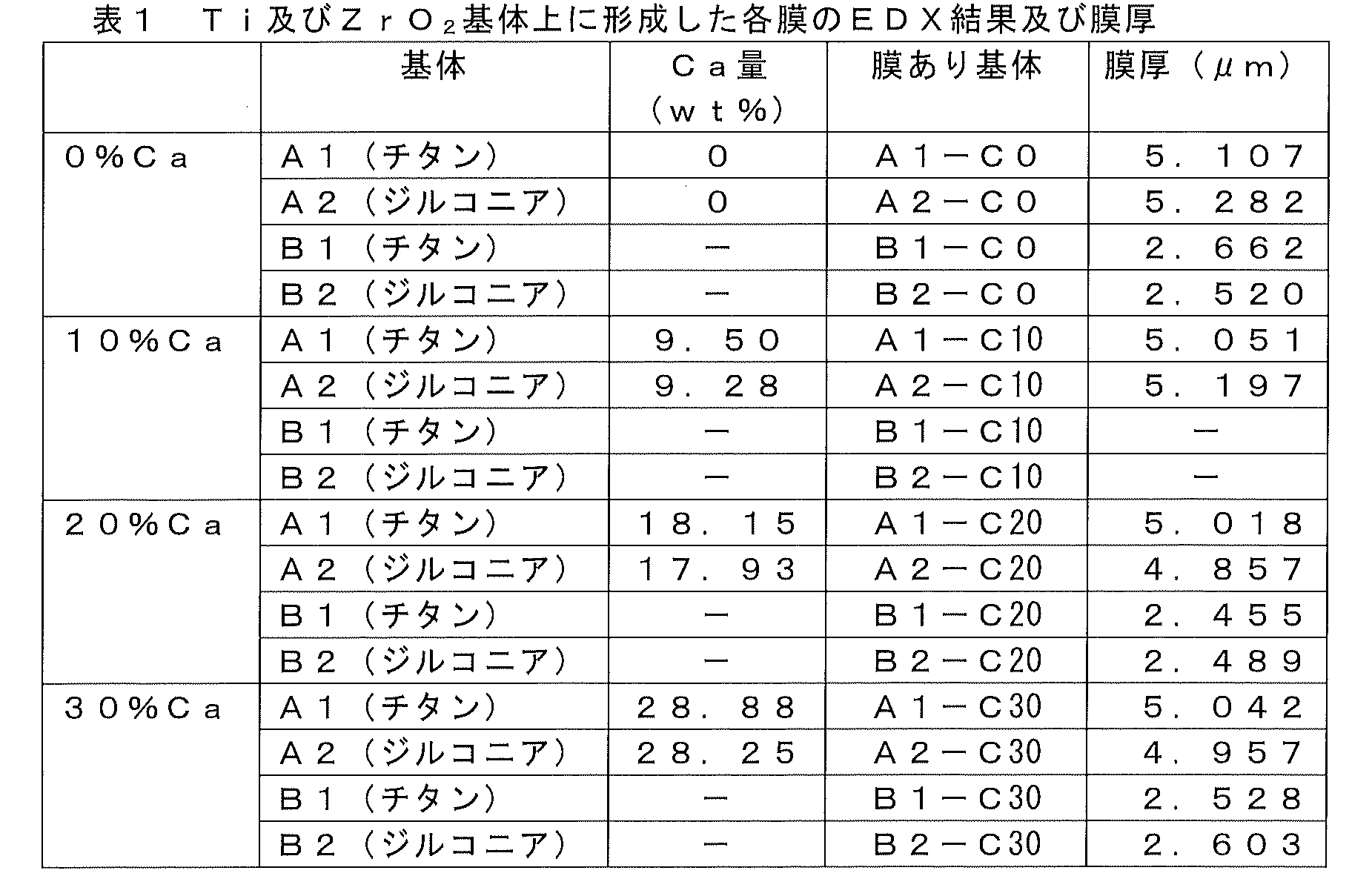
チタンを用いたプレート状基体を用いて成膜したA1-C0、A1-C10、A1-C20及びA1-C30について、及びジルコニアを用いたプレート状基体を用いて成膜したA2-C0、A2-C10、A2-C20及びA2-C30について、その表面の線粗さの算術平均高さRa1を測定した。
また、A1-C0、A1-C10、A1-C20及びA1-C30について、及びジルコニアを用いたプレート状基体を用いて成膜したA2-C0、A2-C10、A2-C20及びA2-C30について、成膜前の表面の線粗さの算術平均高さRa2を測定した。
さらに、A1-C0、A1-C10、A1-C20及びA1-C30について、及びジルコニアを用いたプレート状基体を用いて成膜したA2-C0、A2-C10、A2-C20及びA2-C30について、成膜後の膜を5%塩酸水溶液に10秒程度浸漬することにより除去した。得られた試料の膜を除去した面の線粗さの算術平均高さRa2’を測定した。なお、後述のように、Ra2とRa2’とはほぼ同じであることを確認した。
各試料について、膜を有する表面の線粗さの算術平均高さRa1、膜を有しない表面の線粗さの算術平均高さRa2(=Ra2’)の結果を図3及び図4に示す。
なお、膜を有しない表面の算術平均粗さは、a)成膜前の測定値Ra2とb)成膜後に除去した面の測定値Ra2’とについて測定した。その結果、図示しないが、ほぼ同じ結果であることを確認した。この結果から、b)成膜後の除去方法が適切であることを確認した。
また、図4は、図3での「チタン」に代えて「ジルコニア」を用いたプレート状基体を用いて成膜した試料の結果であり、図3と同様に、斜線ありがRa1の値、斜線なしがRa2の値である。
また、表3は、各試料について、Ra1の値(図3及び図4における、斜線ありの値)とRa2の値(図3及び図4における、斜線なしの値)との差分をまとめたものである。
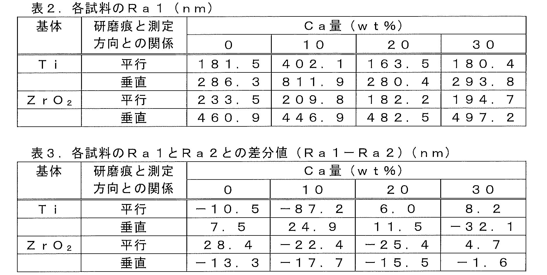
チタンを用いたプレート状基体を用いて成膜したA1-C0、A1-C10、A1-C20及びA1-C30について、及びジルコニアを用いたプレート状基体を用いて成膜したA2-C0、A2-C10、A2-C20及びA2-C30について、その表面の面粗さの算術平均高さSa1を測定した。
また、A1-C0、A1-C10、A1-C20及びA1-C30について、及びジルコニアを用いたプレート状基体を用いて成膜したA2-C0、A2-C10、A2-C20及びA2-C30について、成膜前の表面の面粗さの算術平均高さSa2を測定した。
さらに、A1-C0、A1-C10、A1-C20及びA1-C30について、及びジルコニアを用いたプレート状基体を用いて成膜したA2-C0、A2-C10、A2-C20及びA2-C30について、成膜後の膜を5%塩酸水溶液に10秒程度浸漬することにより除去した。得られた試料の膜を除去した面の面粗さの算術平均高さSa2’を測定した。なお、後述のように、Sa2とSa2’とはほぼ同じであることを確認した。
各試料について、膜を有する表面の面粗さの算術平均高さSa1、膜を有しない表面の面粗さの算術平均高さSa2(=Sa2’)の結果を図5及び図6に示す。
なお、膜を有しない表面の算術平均粗さは、a)成膜前の測定値Sa2とb)成膜後に除去した面の測定値Sa2’とについて測定した。その結果、図示しないが、ほぼ同じ結果であることを確認した。この結果から、b)成膜後の除去方法が適切であることを確認した。
また、図6は、図5での「チタン」に代えて「ジルコニア」を用いたプレート状基体を用いて成膜した試料の結果であり、図5と同様に、斜線ありがSa1の値、斜線なしがSa2の値である。
また、表5は、各試料について、Sa1の値(図5及び図6における、斜線ありの値)とSa2の値(図5及び図6における、斜線なしの値)との差分をまとめたものである。
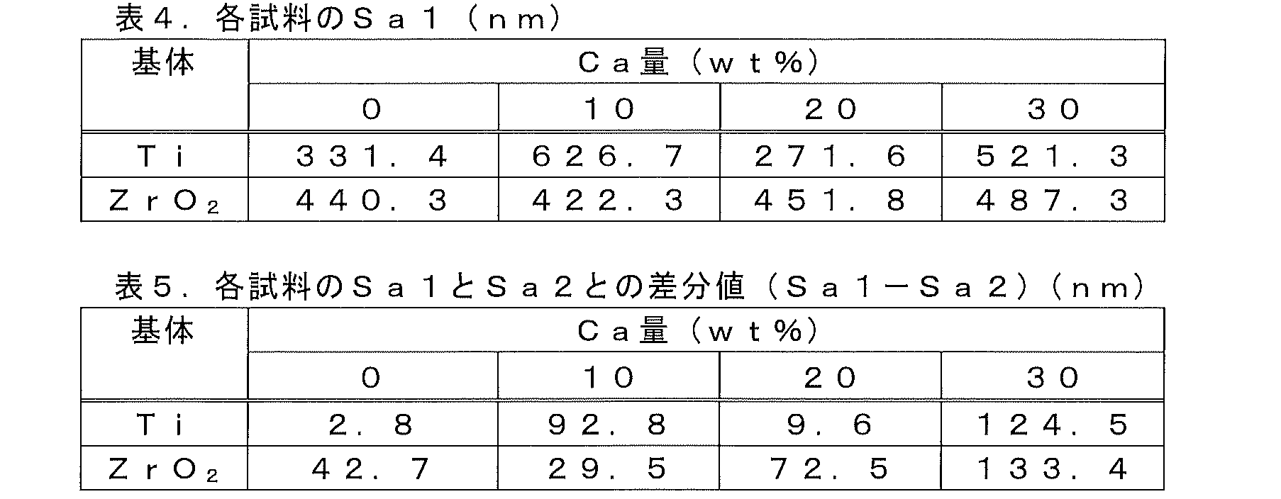
すなわち、例えば歯根用インプラント材料などの埋入において、比較的滑らかな表面粗さを有することが患者の負担軽減及び適切な埋入及び締め込みにおいて重要であるが、それは試料の線粗さの算術平均表面高さの最大値に依存し、且つ面粗さの算術平均表面高さの最大値に依存する。上記表2及び表4から、本実施例では、線粗さ又は面粗さの算術平均表面高さの最大値は、1μm以下であるため、本実施例で得られた試料は、埋入をスムーズに行うことができる。本実施例では、一般的な研削加工を施した基体を用いたが、比較例で後述するように、より滑らかな基体を適用することによって、さらに滑らかな表面粗さにすることも可能である。このような基体は、抜去を前提としたスクリュー(骨ねじやアンカースクリュー)において、埋入後は2次固定までの期間を短縮し、抜去時には基体の表面の凹凸による物理的なかみ合いを抑えて抜去をスムーズに行うことを可能とする。
また、スパッタリングを用いて実施例の膜を形成することにより、各試料のRa1とRa2との差分値(Ra1-Ra2)(nm)、及びSa1とSa2との差分値(Sa1-Sa2)(nm)を比較的小さな値とすることができる。すなわち、比較例で後述するように、膜自体の表面粗さは最大値が30nm以下であることから、膜を形成することによって表面粗さが増加することはほとんどない。
また、差分を小さくすることは、膜が局所的に形成されず、均等に基体の表面を覆って成膜されていることを示すものであり、膜の効果が基体の隅々まで安定して発揮されることが期待できる。
得られた試料について、膜の断面方向と膜を有する面について、走査型電子顕微鏡(SEM)で確認した。
図7は、ガラス基体を用いて成膜したAC1-C0、AC1-C10、AC1-C20及びAC1-C30についての、膜の断面方向の走査型電子顕微鏡像(SEM像)を示す。
図8は、チタンを用いたプレート状基体を用いて成膜したA1-C0、A1-C10、A1-C20及びA1-C30についての、膜を有する面の走査型電子顕微鏡像を示す。
図9はジルコニアを用いたプレート状基体を用いて成膜したA2-C0、A2-C10、A2-C20及びA2-C30についての、膜を有する面の走査型電子顕微鏡像を示す。
また、図8及び図9の上面の外観からも、マグネシウムのみのもの(A1-C0及びA2-C0)は、表面は比較的滑らかではあるが、一部に六角形の柱状の断面が見られる。これはマグネシウム結晶格子である六方稠密構造(HCP)の(0001)面に相当するもので、この方向に結晶が配向していることが分かった。10%カルシウム(A1-C10及びA2-C10)では、方向性のない細かい粒が分散していることがわかる。また、20%カルシウム(A1-C20及びA2-C20)、および30%カルシウム(A1-C30及びA2-C30)ではいずれの場合も、断面と同様に滑らかな面を呈していることがわかる。
得られた試料、ガラス基体を用いて成膜したAC1-C0、AC1-C10、AC1-C20及びAC1-C30の膜、チタンを用いたプレート状基体を用いて成膜したA1-C0、A1-C10、A1-C20及びA1-C30、並びにジルコニアを用いたプレート状基体を用いて成膜したA2-C0、A2-C10、A2-C20及びA2-C30について、X線回折分析を行った。
具体的には、X線回折装置(D8ADVANCE、BRUKER社製)を用いて、検出器:2次元検出器、管球:Co、管球電圧:30kV、管球電流:40mA、スリット:Φ1.0mm、コリメーター:Φ1.0mmという条件でX線回折分析を行った。その結果を図10、図11、図12に示す。
図10から、いずれの膜も2θ=40度付近にピークが見られる。0%カルシウムの場合(AC1-C0)は回折強度が非常に高くシャープであり、マグネシウム中のカルシウムが増えていくにしたがってピークが小さくなり、30%(AC1-C30)ではブロードになってピークが明確に見られなくなる。また、20%カルシウム(AC1-C20)では低いピークは見られるものの、ピークの位置が低角側にシフトしてブロードになってきており、格子間隔が広がって歪んでいることが分かる。図11、図12から、チタンを用いたプレート状基体及びジルコニアを用いたプレート状基体にいずれの膜を成膜した場合においても、同様の結果になることがわかる。
なお、0%カルシウムの膜において、40度付近の(00-2)ピークの強度が著しく高いのは、SEM像(図7、図8、図9)の外観にもみられた結晶の配向性によるものと考えられる。チタンを用いたプレート状基体及びジルコニアを用いたプレート状基体の10%カルシウムの膜において、(00-2)のピークだけでなく、(-10-1)のピークも見られることから、ランダムな配向性をもつ微細結晶であると考えられる。
この構造の変化は、前述した算術平均表面粗さの特徴にも表れている。すなわち、表面粗さは、いずれの試料であっても小さく滑らかである。
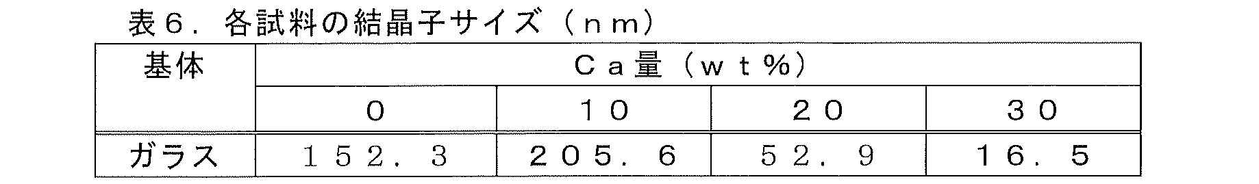
チタンを用いたプレート状基体を用いて成膜したA1-C0、A1-C10、A1-C20及びA1-C30について、及びジルコニアを用いたプレート状基体を用いて成膜したA2-C0、A2-C10、A2-C20及びA2-C30について、ナノインデンテーション法により、硬さ試験を行った。
圧子:バーコビッチ圧子;押込み荷重;20mN;保持時間:0秒;の条件下、装置(エリオニクス社超微小押込み硬さ試験機「ENT-1100A」)を用いて、ナノインデンテーション法の硬さ試験を行った。
硬さ試験の結果を図13に示す。
図13から、いずれの膜も、骨の硬さ0.4~0.9GPaを上回り、骨に対して十分な「耐摩耗性」を有していることがわかった。
チタンを用いたプレート状基体を用いて成膜したA1-C0、A1-C10、A1-C20及びA1-C30について、及びジルコニアを用いたプレート状基体を用いて成膜したA2-C0、A2-C10、A2-C20及びA2-C30について、スクラッチ試験を行った。
スクラッチ試験装置は、Scrach tester CSR1000(株式会社レスカ製)を用い、径0.8mmのロックウェル圧子を使用して、荷重を0~8kg重の範囲で与えた。SEM/EDXでスクラッチ試験後の試料を観察し、スクラッチ試験の初期位置から基体が露出した位置までの距離を測定して臨界荷重を求めた。
図14、図15から、すべての膜において、膜の部分的な剥離は見られず「密着性」が良好であることが分かった。これにより、表面に力が加わったときに、膜の耐摩耗性が十分に発揮できることがわかった。
図17は、ジルコニアを用いたプレート状基体を用いて成膜したA2-C0、A2-C10、A2-C20及びA2-C30の研削痕に平行あるいは垂直方向のスクラッチ試験において、圧子がほぼ基体まで到達したときの荷重、すなわち膜の臨界荷重を見出すための測定結果である。なお、臨界荷重は、膜の密着性の度合いも示す。
チタンを用いたプレート状基体を用いて成膜したA1-C0、A1-C10、A1-C20及びA1-C30、ジルコニアを用いたプレート状基体を用いて成膜したA2-C0、A2-C10、A2-C20及びA2-C30のうち、研削痕に平行方向のスクラッチ試験におけるA1-C10、研削痕に垂直方向のスクラッチ試験におけるA1-C10、A1-C20、A1-C30が臨界荷重78.4N以上であり優れていることがわかる。
臨界荷重が最も小さいA2-C0であっても、約10Nであり、臨界荷重が10N以上を満足している。臨界荷重約10Nは、スクリューの半径を2mm、ねじ山の先端の幅を0.2mmのインプラントスクリューにおいて、膜が剥離することなく埋入可能な埋入トルクが150Ncmに相当する。該150Ncmは、インプラントに要求される埋入トルク35~45Ncmに対し、約4倍の安全率の強度を有し、本実施例の膜が所望の密着性を有することがわかる。
界面の臨界せん断応力は、スクラッチ試験の結果を用いて求めることができる。
スクラッチ試験では、膜の表面に圧子を通して荷重Wを与え、この圧子先端を膜に平行に引き摺る(スキッドさせる)ことにより、膜が剥がされて基体表面が露出するまでの長さを測る。圧子の荷重は、引き摺り長さと比例関係になるように設定されているので、この長さから、膜が剥がされた時の臨界荷重Wcが分かる。この時、膜の破壊あるいは変形の外観を観察することにより、膜の脆さや延性もわかる。ここでは、一般に使われているBenjamine-Weaverの式をもちいて求める。
すなわち、膜が壊れた時の荷重を臨界荷重Wcとし、ダイヤモンド製圧子の先端の半径をRとし、基体のブリネルの硬さをHBとすると、このときの界面のせん断応力τc(臨界せん断応力)は式5のようにあらわされる。

膜の降伏応力は膜の界面のせん断応力よりも小さく、表面にせん断力が加わったときに、界面より先に膜の方が延性的に変形して、膜の界面から剥離することがないことがわかる。このことは、図14、図15のスクラッチ試験の外観に現れていた。
チタンを用いたプレート状基体を用いて成膜したA1-C0、A1-C10、A1-C20及びA1-C30について、及びジルコニアを用いたプレート状基体を用いて成膜したA2-C0、A2-C10、A2-C20及びA2-C30について、擬似体液をもちいたin vitroの生体反応試験を行った。
擬似体液浸漬試験として、擬似体液400mlに各試料を浸漬させ、37℃の恒温槽中で1週間保持した後、サンプルを溶液から取り出した。
また、溶液中の平衡pHを生体内環境に近づけるため、スパッタリング膜溶出後の平衡pHが8.0以下となるようにHBSS(+)の溶液量を調整した。比較のために膜のないそれぞれの基体についても試験をおこなった。
また、図示しないが、スパッタリング膜を成膜しなかったチタンおよびジルコニアの基体では、HBSS中で新たな膜は形成されなかったが、スパッタリングにより成膜した0%カルシウム(純マグネシウム)から30%カルシウムまでの基体では、新たな膜の形成が認められた。また、カルシウムを10%以上含む膜は、新しい膜の付着量が多いことが観察された。
図21に、ジルコニアを用いたプレート状基体を用いて成膜したA2-C0、A2-C10、A2-C20及びA2-C30をHBSSに一週間浸漬し基体上に新たに形成された膜のSEM像を示す。
また、SEM像におけるほぼ中心(詳細には、SEM像中の「+」の位置)における、蛍光X線により行った成分分析の結果を表7に示す。
また、上記膜の構造を解析するために、X線入射角を固定して検出器のみをスキャンする薄膜法によるX線回折(XRD)分析を行った。その結果を図22、図23に示す。
チタン基体上、ジルコニア基体上ともにアパタイトの特徴を表す回折角度にピークがスパッタリングされたほとんどの基体に現れた。A2-C0では、アパタイトのピークが確認されなかったが、図21、表7に示したように表面上にアパタイトは存在している。このことから、他のスパッタリング膜を有する試料と比べるとA2-C0に形成されたアパタイト量が少ないことがわかる。
このように成分分析および構造解析より、スパッタリング膜を有するすべての基体上にアパタイトが形成されたことが確認できた。また、スパッタリング膜にカルシウムを含有させることで、形成されるアパタイト量が多くなることが確認できた。
図24に、膜のみの表面粗さを評価するために表面が滑らかなガラス基体を用いてアークイオンプレーティングで純マグネシウムを成膜した試料AIPC1-C0とガラス基体を用いてスパッタリングで成膜したAC1-C0、AC1-C10、AC1-C20及びAC1-C30の線粗さの算術平均高さRa1の比較を示す。アークイオンプレーティングで純マグネシウムを成膜した試料とスパッタリングで成膜した試料の表面粗さを比較すると、成膜前のガラス基体に対してアークイオンプレーティングで純マグネシウムを成膜することで、Raが2.5μm以上増加することがわかる。一方、スパッタリングで純マグネシウムを成膜した場合は、Raが0.03μm以下しか増加しないことがわかる。さらに、カルシウムを含有することで、成膜時の粗さの上昇がより抑えられることがわかる。
これらのことから、非晶質かつMg2Caフリーの構造によって非脆性な特性を有し、高い臨界荷重を示すことがわかる。一方、Mg2Caが存在して脆性な場合、臨界荷重が大幅に低いことがわかる。
特許文献2にあるチタン酸カルシウム膜の密着強度:4.9MPaであり、非特許文献2にあるリン酸カルシウムコーティング膜の密着強度:80MPaである。これらは、接着材を用いたピン引張試験で得られた引張強度である。
本願の膜の引張強度を同様のピン引張試験で測定したが、接着剤の方が先に破壊するほど引張強度が強すぎて測定不可能であった。ピン引張試験で密着強度を測定できない試料は、より強い密着強度の測定が可能なスクラッチ試験などを用いるのが一般的である。経済産業省が発行した体内埋め込み型材料分野開発ガイドライン2008によると、膜の引張強度及びせん断強度はともに20MPa以上であることが望ましいとされている。そのため、本実施例で算出したせん断応力と先行技術における引張強度は同じ水準で密着強度として比較できる。したがって、本実施例で算出した中で最も低いA2-C20の密着強度:170MPaであっても、先行技術と比較すると極めて高い値であることがわかる。
Claims (19)
- マグネシウム及び任意にカルシウムを有してなる膜を有する生体適合性材料であって、
前記膜は、マグネシウムとカルシウムとの合計の重量を100重量%とすると、カルシウムが0~40重量%有し、
前記膜の面粗さの算術平均表面高さSa1が2μm以下である、上記生体適合性材料。 - マグネシウム及び任意にカルシウムを有してなる膜を有する生体適合性材料であって、
前記膜は、マグネシウムとカルシウムとの合計の重量を100重量%とすると、カルシウムが0~40重量%有し、
前記膜の面粗さの算術平均表面高さSa1と前記膜を有しない表面の面粗さの算術平均表面高さSa2との差分が300nm以下である、上記生体適合性材料。 - 前記膜の面粗さの算術平均表面高さSa1が2μm以下である請求項2に記載の生体適合性材料。
- マグネシウム及び任意にカルシウムを有してなる膜を有する生体適合性材料であって、
前記膜は、マグネシウムとカルシウムとの合計の重量を100重量%とすると、カルシウムが0~40重量%有し、
前記膜は、下記i)~iii)のうちいずれか一つ、又は二つ、又は全て、の特性を有する、上記生体適合性材料:
i)インデンテーション試験により得られる硬度が0.4GPa以上である;
ii)臨界荷重Wc(N)と膜厚t(μm)との関係Wc/tが、1N/μm以上である;
iii)膜と基体の界面の臨界せん断応力が80MPa以上である。 - マグネシウム及び任意にカルシウムを有してなる膜を有する生体適合性材料であって、
前記膜は、マグネシウムとカルシウムとの合計の重量を100重量%とすると、カルシウムが0~40重量%有し、
前記膜の線粗さの算術平均表面高さRa1が2μm以下である、上記生体適合性材料。 - マグネシウム及び任意にカルシウムを有してなる膜を有する生体適合性材料であって、
前記膜は、マグネシウムとカルシウムとの合計の重量を100重量%とすると、カルシウムが0~40重量%有し、
前記膜の線粗さの算術平均表面高さRa1と前記膜を有しない表面の線粗さの算術平均表面高さRa2との差分が300nm以下である、上記生体適合性材料。 - 前記膜の線粗さの算術平均表面高さRa1が2μm以下である請求項6に記載の生体適合性材料。
- c)前記膜の面粗さの算術平均表面粗さSa1が2μm以下であるか、及び/又は
d)前記膜の面粗さの算術平均表面高さSa1と前記膜を有しない表面の面粗さの算術平均表面高さSa2との差分が300nm以下である、
請求項5~7のいずれか一項に記載の生体適合性材料。 - 下記a)~d)のうちいずれか一つ、又は二つ、又は三つ、又は全て、の特性を有する請求項4に記載の生体適合性材料:
a)前記膜の面粗さの算術平均表面粗さSa1が2μm以下である、
b)前記膜の面粗さの算術平均表面高さSa1と前記膜を有しない表面の面粗さの算術平均表面高さSa2との差分が300nm以下である、
c)前記膜の線粗さの算術平均表面高さRa1が2μm以下である、
d)前記膜の線粗さの算術平均表面高さRa1と前記膜を有しない表面の線粗さの算術平均表面高さRa2との差分が300nm以下である。 - 前記膜の平均厚さが0.10~30μmである請求項1~9のいずれか一項に記載の生体適合性材料。
- 前記膜が、マグネシウムのみから本質的になる請求項1~10のいずれか一項に記載の生体適合性材料。
- 前記膜が、マグネシウム及びカルシウムを有してなり、前記膜は、マグネシウムとカルシウムとの合計の重量を100重量%とすると、カルシウムが0重量%を越えて40重量%以下有する請求項1~10のいずれか一項に記載の生体適合性材料。
- 前記膜がMg2Caフリーである請求項12に記載の生体適合性材料
- 前記膜が非晶質部分を有する請求項12又は13に記載の生体適合性材料。
- 前記生体適合性材料が生体適合性基体を有し、該生体適合性基体が、純チタニウム、ジルコニア、コバルトクロム合金、ステンレス鋼及びチタン合金からなる群から選ばれる少なくとも1種である請求項1~14のいずれか一項に記載の生体適合性材料。
- 前記生体適合性材料が、人工骨材料、骨内固定器具材料、歯科用インプラント材料、歯科矯正用アンカースクリュー材料、髄内釘材料、及び椎体間固定材料からなる群から選ばれる1種である請求項1~15のいずれか一項に記載の生体適合性材料。
- 前記生体適合性材料の形状が、円筒状、円錐台状及び円錐状、並びに該形状の一部にスクリュー状のねじ部を備えた形状、直方体及び立方体、並びに一部傾斜面を有するブロック形状、及びくさび形状からなる群から選ばれる1種である請求項1~16のいずれか一項に記載の生体適合性材料。
- (A)生体適合性基体を準備する工程;
(B)マグネシウム及び任意にカルシウムを有してなるスパッタターゲットを準備する工程;
(C)前記生体適合性基体の表面を真空中でクリーニングする工程;及び
(D)前記スパッタターゲットを用いて、前記(C)工程で得られた生体適合性基体の温度を130℃以下として、スパッタリングにより前記生体適合性基体にマグネシウム及び任意にカルシウムを有してなる膜を形成する工程;
を有することにより、
マグネシウム及び任意にカルシウムを有してなる膜を有する生体適合性材料であって、前記膜は、マグネシウムとカルシウムとの合計の重量を100重量%とすると、カルシウムが0~40重量%有する生体適合性材料を得る、生体適合性材料の製造方法。 - 下記a)~d)のうちいずれか一つ、又は二つ、又は三つ、又は全て、の特性を有する請求項18に記載の方法:
a)前記膜の面粗さの算術平均表面粗さSa1が2μm以下である、
b)前記膜の面粗さの算術平均表面高さSa1と前記膜を有しない表面の面粗さの算術平均表面高さSa2との差分が300nm以下である、
c)前記膜の線粗さの算術平均表面高さRa1が2μm以下である、
d)前記膜の線粗さの算術平均表面高さRa1と前記膜を有しない表面の線粗さの算術平均表面高さRa2との差分が300nm以下である。
Priority Applications (5)
| Application Number | Priority Date | Filing Date | Title |
|---|---|---|---|
| AU2021373463A AU2021373463A1 (en) | 2020-11-05 | 2021-11-04 | Biocompatible material and method of producing same |
| KR1020237018357A KR20230104197A (ko) | 2020-11-05 | 2021-11-04 | 생체 적합성 재료 및 그 제조 방법 |
| CN202180074920.6A CN116472072A (zh) | 2020-11-05 | 2021-11-04 | 生物相容性材料及其制造方法 |
| EP21889223.0A EP4241796A1 (en) | 2020-11-05 | 2021-11-04 | Biocompatible material and method of producing same |
| US18/034,561 US20240050624A1 (en) | 2020-11-05 | 2021-11-04 | Biocompatible material and method of producing same |
Applications Claiming Priority (4)
| Application Number | Priority Date | Filing Date | Title |
|---|---|---|---|
| JP2020184954A JP2022074692A (ja) | 2020-11-05 | 2020-11-05 | 生体適合性材料及びその製造方法 |
| JP2020-184954 | 2020-11-05 | ||
| JP2020217810A JP7370078B2 (ja) | 2020-12-25 | 2020-12-25 | 生体適合性材料及びその製造方法 |
| JP2020-217810 | 2020-12-25 |
Publications (1)
| Publication Number | Publication Date |
|---|---|
| WO2022097670A1 true WO2022097670A1 (ja) | 2022-05-12 |
Family
ID=81457087
Family Applications (1)
| Application Number | Title | Priority Date | Filing Date |
|---|---|---|---|
| PCT/JP2021/040544 WO2022097670A1 (ja) | 2020-11-05 | 2021-11-04 | 生体適合性材料及びその製造方法 |
Country Status (5)
| Country | Link |
|---|---|
| US (1) | US20240050624A1 (ja) |
| EP (1) | EP4241796A1 (ja) |
| KR (1) | KR20230104197A (ja) |
| AU (1) | AU2021373463A1 (ja) |
| WO (1) | WO2022097670A1 (ja) |
Cited By (1)
| Publication number | Priority date | Publication date | Assignee | Title |
|---|---|---|---|---|
| WO2023032948A1 (ja) * | 2021-08-31 | 2023-03-09 | 株式会社丸ヱム製作所 | 生体適合性膜、及び該膜を有する生体適合性材料 |
Citations (6)
| Publication number | Priority date | Publication date | Assignee | Title |
|---|---|---|---|---|
| JPH032540A (ja) | 1989-05-30 | 1991-01-08 | Shimadzu Corp | 漏れ試験方法とパッケージ形電子ディバイス |
| EP1847278A1 (de) | 2006-04-13 | 2007-10-24 | Camlog Biotechnologies AG | Bio-auflösende Salzbeschichtungen von Implantaten zum Schutz vor organischen Verunreinigungen |
| WO2009147819A1 (ja) | 2008-06-03 | 2009-12-10 | 学校法人中部大学 | 骨修復材料及びその製造方法 |
| JP4425198B2 (ja) | 2005-09-16 | 2010-03-03 | 亨 高木 | チタン酸カルシウム・非晶質炭素複合物、それを用いた被覆材、およびその製造方法 |
| WO2016189099A1 (en) | 2015-05-26 | 2016-12-01 | Straumann Holding Ag | Process for the preparation of a topography for improved protein adherence on a body made of titanium or a titanium alloy |
| WO2020099334A2 (en) | 2018-11-12 | 2020-05-22 | Nobel Biocare Services Ag | Dental implant, component for dental applications, implant system for dental applications, method for forming a protective layer on the surface of an implantable or implant component, implantable or implant component having a protective layer, and use of a protective layer |
-
2021
- 2021-11-04 KR KR1020237018357A patent/KR20230104197A/ko unknown
- 2021-11-04 WO PCT/JP2021/040544 patent/WO2022097670A1/ja active Application Filing
- 2021-11-04 US US18/034,561 patent/US20240050624A1/en active Pending
- 2021-11-04 EP EP21889223.0A patent/EP4241796A1/en active Pending
- 2021-11-04 AU AU2021373463A patent/AU2021373463A1/en active Pending
Patent Citations (6)
| Publication number | Priority date | Publication date | Assignee | Title |
|---|---|---|---|---|
| JPH032540A (ja) | 1989-05-30 | 1991-01-08 | Shimadzu Corp | 漏れ試験方法とパッケージ形電子ディバイス |
| JP4425198B2 (ja) | 2005-09-16 | 2010-03-03 | 亨 高木 | チタン酸カルシウム・非晶質炭素複合物、それを用いた被覆材、およびその製造方法 |
| EP1847278A1 (de) | 2006-04-13 | 2007-10-24 | Camlog Biotechnologies AG | Bio-auflösende Salzbeschichtungen von Implantaten zum Schutz vor organischen Verunreinigungen |
| WO2009147819A1 (ja) | 2008-06-03 | 2009-12-10 | 学校法人中部大学 | 骨修復材料及びその製造方法 |
| WO2016189099A1 (en) | 2015-05-26 | 2016-12-01 | Straumann Holding Ag | Process for the preparation of a topography for improved protein adherence on a body made of titanium or a titanium alloy |
| WO2020099334A2 (en) | 2018-11-12 | 2020-05-22 | Nobel Biocare Services Ag | Dental implant, component for dental applications, implant system for dental applications, method for forming a protective layer on the surface of an implantable or implant component, implantable or implant component having a protective layer, and use of a protective layer |
Non-Patent Citations (14)
| Title |
|---|
| AYUKAWA YASUNORI, ATSUTA IKIRU, TSURUTA KATSUHIRO, MATSUSHITA YASUYUKI, KOYANO KIYOSHI: "State-of-the-art of the Surface Modification of Oral Implants", HYOMEN GIJUTSU - JOURNAL OF THE SURFACE FINISHING SOCIETY OFJAPAN, HYOMEN GIJUTSU KYOKAI, TOKYO, JP, vol. 67, no. 6, 1 June 2016 (2016-06-01), JP , pages 297 - 301, XP055928421, ISSN: 0915-1869, DOI: 10.4139/sfj.67.297 * |
| G.E. DIETER: "Mechanical metallurgy", 1988, MCGRAW-HILL |
| HARRISON RICHARD; MARADZE DIANA; LYONS SIMON; ZHENG YUFENG; LIU YANG: "Corrosion of magnesium and magnesium–calcium alloy in biologically-simulated environ", PROGRESS IN NATURAL SCIENCE: MATERIALS INTERNATIONAL, ELSEVIER, AMSTERDAM, NL, vol. 24, no. 5, 29 October 2014 (2014-10-29), AMSTERDAM, NL, pages 539 - 546, XP029105305, ISSN: 1002-0071, DOI: 10.1016/j.pnsc.2014.08.010 * |
| HORIUCHI, KATSUHIRO: "Relation between the Shape/Surface of the Implant Collar and Peri-Implantitis", JOURNAL OF JAPANESE SOCIETY OF ORAL IMPLANTOLOGY, vol. 29, no. 4, 31 December 2016 (2016-12-31), JP , pages 208 - 218, XP009536431, ISSN: 0914-6695, DOI: 10.11237/jsoi.29.208 * |
| IBASCO, S. ; TAMIMI, F. ; MESZAROS, R. ; NIHOUANNEN, D.L. ; VENGALLATORE, S. ; HARVEY, E. ; BARRALET, J.E.: "Magnesium-sputtered titanium for the formation of bioactive coatings", ACTA BIOMATERIALIA, ELSEVIER, AMSTERDAM, NL, vol. 5, no. 6, 1 July 2009 (2009-07-01), AMSTERDAM, NL, pages 2338 - 2347, XP026161800, ISSN: 1742-7061, DOI: 10.1016/j.actbio.2009.03.006 * |
| IMPLANT JOURNAL 2017, AUTUMN, pages 8 |
| J. HOFSTETER ET AL., JOM, vol. 68, no. 4, 2014, pages 566 - 572 |
| J. LI ET AL., CHEMICAL COMMUNICATIONS, vol. 53, 2017, pages 8288 - 8291 |
| J. LIU ET AL., J. ALLOYS AND COMPOUNDS, vol. 742, 2018, pages 524 - 535 |
| K. L. JOHNSON: "Contact mechanics", 1985, CAMBRIDGE UNIVERSITY PRESS |
| K. SAKSL ET AL., J. ALLOYS AND COMPOUNDS, vol. 801, 2019, pages 651 - 657 |
| KYOUSUKE UEDA, MATERIA JAPAN, vol. 51, no. 9, 2012 |
| LI ET AL., SCIENTIFIC REPORTS, vol. 7, 2017, pages 40755 |
| S. PAUL, S25 MATERIALIA, 2020 |
Cited By (1)
| Publication number | Priority date | Publication date | Assignee | Title |
|---|---|---|---|---|
| WO2023032948A1 (ja) * | 2021-08-31 | 2023-03-09 | 株式会社丸ヱム製作所 | 生体適合性膜、及び該膜を有する生体適合性材料 |
Also Published As
| Publication number | Publication date |
|---|---|
| AU2021373463A1 (en) | 2023-06-22 |
| KR20230104197A (ko) | 2023-07-07 |
| US20240050624A1 (en) | 2024-02-15 |
| EP4241796A1 (en) | 2023-09-13 |
| AU2021373463A9 (en) | 2024-05-02 |
Similar Documents
| Publication | Publication Date | Title |
|---|---|---|
| Li et al. | Electrochemical and surface analyses of nanostructured Ti–24Nb–4Zr–8Sn alloys in simulated body solution | |
| Xu et al. | Corrosion behavior of Ti–Nb–Ta–Zr–Fe alloy for biomedical applications in Ringer's solution | |
| US8535722B2 (en) | Functionally graded biocompatible coating and coated implant | |
| Gkomoza et al. | Comparative study of structure and properties of thermal spray coatings using conventional and nanostructured hydroxyapatite powder, for applications in medical implants | |
| Frutos et al. | Development of new β/α ″-Ti-Nb-Zr biocompatible coating with low Young's modulus and high toughness for medical applications | |
| WO2022097670A1 (ja) | 生体適合性材料及びその製造方法 | |
| JP7388770B2 (ja) | 生体適合性材料及びその製造方法 | |
| Pereira et al. | Oxide coating containing apatite formed on Ti-25Nb-25Ta alloy treated by Two-Step Plasma Electrolytic Oxidation | |
| Sawase et al. | Application of oxygen ion implantation to titanium surfaces: effects on surface characteristics, corrosion resistance, and bone response | |
| JP2022074692A (ja) | 生体適合性材料及びその製造方法 | |
| Vladescu et al. | The effect of TiSiN interlayers on the bond strength of ceramic to NiCr and CoCr alloys | |
| Yankov et al. | Changes in the mechanical properties of Ti samples with TiN and TiN/TiO2 coatings deposited by different PVD methods | |
| Kong et al. | Hydroxyapatite‐based composite for dental implants: An in vivo removal torque experiment | |
| Sun et al. | Bioactive (Si, O, N)/(Ti, O, N)/Ti composite coating on NiTi shape memory alloy for enhanced wear and corrosion performance | |
| Anuradha et al. | Reliability performance of titanium sputter coated Ni–Ti arch wires: Mechanical performance and nickel release evaluation | |
| US9757498B2 (en) | Bonded alumina coating for stainless steel | |
| TWI589277B (zh) | 高抗機械疲勞的根管銼針 | |
| Carradò et al. | Nanocrystalline thin ceramic films synthesised by pulsed laser deposition and magnetron sputtering on metal substrates for medical applications | |
| Ozdemir et al. | Optimizing mechanical properties and Ag ion release rate of silver coatings deposited on Ti-based high entropy alloys | |
| WO2023032948A1 (ja) | 生体適合性膜、及び該膜を有する生体適合性材料 | |
| Zhang et al. | Fabrication of Ta2O5 reinforced Ta-Based Coatings on Ta Substrates by Laser Cladding | |
| WO2023032947A1 (ja) | 生体適合性材料およびその製造方法 | |
| Maya et al. | Microstructural and tribological properties of TiO2/Ag multilayer coatings using magnetron sputtering technique for potential applications in non-permanent implants | |
| Topuz et al. | Synthesis of implantable ceramic coatings and their properties | |
| Carradò et al. | Interface and in bulk residual stress analysis in biomedical systems by non-destructive techniques |
Legal Events
| Date | Code | Title | Description |
|---|---|---|---|
| 121 | Ep: the epo has been informed by wipo that ep was designated in this application |
Ref document number: 21889223 Country of ref document: EP Kind code of ref document: A1 |
|
| WWE | Wipo information: entry into national phase |
Ref document number: 202180074920.6 Country of ref document: CN |
|
| ENP | Entry into the national phase |
Ref document number: 20237018357 Country of ref document: KR Kind code of ref document: A |
|
| NENP | Non-entry into the national phase |
Ref country code: DE |
|
| ENP | Entry into the national phase |
Ref document number: 2021889223 Country of ref document: EP Effective date: 20230605 |
|
| ENP | Entry into the national phase |
Ref document number: 2021373463 Country of ref document: AU Date of ref document: 20211104 Kind code of ref document: A |