WO2022097571A1 - 射出装置 - Google Patents
射出装置 Download PDFInfo
- Publication number
- WO2022097571A1 WO2022097571A1 PCT/JP2021/039937 JP2021039937W WO2022097571A1 WO 2022097571 A1 WO2022097571 A1 WO 2022097571A1 JP 2021039937 W JP2021039937 W JP 2021039937W WO 2022097571 A1 WO2022097571 A1 WO 2022097571A1
- Authority
- WO
- WIPO (PCT)
- Prior art keywords
- inner diameter
- hollow portion
- seal case
- barrel
- nozzle
- Prior art date
- Legal status (The legal status is an assumption and is not a legal conclusion. Google has not performed a legal analysis and makes no representation as to the accuracy of the status listed.)
- Ceased
Links
Images




Classifications
-
- B—PERFORMING OPERATIONS; TRANSPORTING
- B29—WORKING OF PLASTICS; WORKING OF SUBSTANCES IN A PLASTIC STATE IN GENERAL
- B29C—SHAPING OR JOINING OF PLASTICS; SHAPING OF MATERIAL IN A PLASTIC STATE, NOT OTHERWISE PROVIDED FOR; AFTER-TREATMENT OF THE SHAPED PRODUCTS, e.g. REPAIRING
- B29C45/00—Injection moulding, i.e. forcing the required volume of moulding material through a nozzle into a closed mould; Apparatus therefor
- B29C45/17—Component parts, details or accessories; Auxiliary operations
- B29C45/1775—Connecting parts, e.g. injection screws, ejectors, to drive means
-
- B—PERFORMING OPERATIONS; TRANSPORTING
- B29—WORKING OF PLASTICS; WORKING OF SUBSTANCES IN A PLASTIC STATE IN GENERAL
- B29C—SHAPING OR JOINING OF PLASTICS; SHAPING OF MATERIAL IN A PLASTIC STATE, NOT OTHERWISE PROVIDED FOR; AFTER-TREATMENT OF THE SHAPED PRODUCTS, e.g. REPAIRING
- B29C45/00—Injection moulding, i.e. forcing the required volume of moulding material through a nozzle into a closed mould; Apparatus therefor
- B29C45/17—Component parts, details or accessories; Auxiliary operations
- B29C45/46—Means for plasticising or homogenising the moulding material or forcing it into the mould
- B29C45/58—Details
- B29C45/586—Injection or transfer plungers
-
- B—PERFORMING OPERATIONS; TRANSPORTING
- B29—WORKING OF PLASTICS; WORKING OF SUBSTANCES IN A PLASTIC STATE IN GENERAL
- B29C—SHAPING OR JOINING OF PLASTICS; SHAPING OF MATERIAL IN A PLASTIC STATE, NOT OTHERWISE PROVIDED FOR; AFTER-TREATMENT OF THE SHAPED PRODUCTS, e.g. REPAIRING
- B29C45/00—Injection moulding, i.e. forcing the required volume of moulding material through a nozzle into a closed mould; Apparatus therefor
- B29C45/17—Component parts, details or accessories; Auxiliary operations
- B29C45/46—Means for plasticising or homogenising the moulding material or forcing it into the mould
- B29C45/47—Means for plasticising or homogenising the moulding material or forcing it into the mould using screws
-
- B—PERFORMING OPERATIONS; TRANSPORTING
- B29—WORKING OF PLASTICS; WORKING OF SUBSTANCES IN A PLASTIC STATE IN GENERAL
- B29C—SHAPING OR JOINING OF PLASTICS; SHAPING OF MATERIAL IN A PLASTIC STATE, NOT OTHERWISE PROVIDED FOR; AFTER-TREATMENT OF THE SHAPED PRODUCTS, e.g. REPAIRING
- B29C45/00—Injection moulding, i.e. forcing the required volume of moulding material through a nozzle into a closed mould; Apparatus therefor
- B29C45/17—Component parts, details or accessories; Auxiliary operations
- B29C45/46—Means for plasticising or homogenising the moulding material or forcing it into the mould
- B29C45/53—Means for plasticising or homogenising the moulding material or forcing it into the mould using injection ram or piston
Definitions
- the present invention relates to an injection device that injects a molding material.
- Japanese Patent Publication No. 06-086912 discloses an extruder for an injection molding machine. In this extruder, a sealing material is used to prevent the raw material resin from leaking to the outside.
- the present invention aims to solve the above-mentioned problems.
- the injection device is an injection device that injects a molding material into a mold from a nozzle member provided at the tip of the barrel to perform molding, and is provided in the barrel and the hollow inner diameter of the nozzle member.
- a plunger capable of moving in the front-rear direction along the axial direction, an injection hole provided in the nozzle member so that the molding material is injected into the inner diameter hollow portion of the nozzle member, and an injection hole.
- An annular seal provided on the rear side to prevent the molding material injected from the injection hole from flowing backward along the plunger, and a hollow portion having an outer diameter of the inner diameter hollow portion holding the seal.
- a tubular seal case larger than the diameter of the seal case is provided.
- the seal case has a first inner diameter surface that is fixed by the barrel and the nozzle attached to the barrel and forms a first inner diameter hollow portion through which the plunger penetrates, and the first inner diameter hollow portion. It has a second inner diameter surface having a larger diameter and forming a second inner diameter hollow portion into which the seal is fitted, which is coaxial with the first inner diameter hollow portion.
- a female screw portion larger than the diameter of the plunger is formed on at least a part of the first inner diameter surface.
- the injection device is an injection device that injects a molding material into a mold from a nozzle provided at the tip of the barrel to perform molding, and is provided in the hollow portion of the inner diameter of the barrel and is provided in the axial direction.
- a screw that can move in the front-rear direction along the barrel, an injection hole provided in the barrel so that the molding material is injected into the inner diameter hollow portion of the barrel, and a rearward side of the injection hole.
- An annular seal provided to prevent the molding material injected from the injection hole from flowing backward along the screw, and holding the seal, the outer diameter being the diameter of the inner diameter hollow portion of the barrel. It comprises a larger tubular seal case.
- the seal case has a first inner diameter surface that is fixed to the barrel and forms a first inner diameter hollow portion through which the screw penetrates, and the first inner diameter hollow portion that has a larger diameter than the first inner diameter hollow portion. It has a second inner diameter surface that forms a second inner diameter hollow portion into which the seal coaxial with the inner diameter hollow portion is inserted.
- a female thread portion larger than the diameter of the screw is formed on at least a part of the first inner diameter surface.
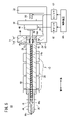
- FIG. 1 is a diagram showing an injection molding machine according to the first embodiment.
- FIG. 2 is an enlarged view showing a part of the injection device according to the first embodiment.
- FIG. 3 is a diagram showing a state in which the seal and the seal case are separated from the nozzle adapter.
- FIG. 4 is a diagram showing an injection molding machine according to the second embodiment.
- FIG. 5 is a diagram showing an injection molding machine according to a third embodiment.
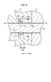
- FIG. 6 is a diagram showing a seal case according to the first modification.
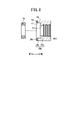
- FIG. 7 is a diagram showing a seal case according to the modified example 2.
- FIG. 8 is a diagram showing a seal case according to the modified example 3.
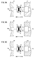
- 9A to 9C are views showing an injection molding machine according to an example of the modified example 4.
- 10A to 10C are views showing an injection molding machine according to another example of the modified example 4.
- the injection molding machine includes a machine base, a mold clamping device, and an injection device.
- the mold clamping device and the injection device are installed on the machine base so as to face each other.
- the mold clamping device has a mold that can be opened and closed.
- the injection device has a barrel and a nozzle.
- the injection molding machine executes the molding cycle under the control of the control device.
- the molding cycle is a process of molding a molding material by injecting the molding material into a mold from a nozzle at the tip of the barrel.
- the molding cycle includes a weighing step and an injection step.
- the injection molding machine of this embodiment is characterized by an injection device. Therefore, the injection device will be described in detail, and the description of other configurations will be omitted.
- FIG. 1 is a diagram showing an injection molding machine 10 according to the first embodiment.
- the configuration of the injection device 12 is mainly shown, and the machine base and the mold clamping device are not shown.
- the injection device 12 includes a barrel 14, a nozzle 18, and a plunger 20.
- the nozzle 18 is attached to the tip of the barrel 14 via the nozzle adapter 16.
- the plunger 20 is arranged inside the barrel 14 and the nozzle adapter 16.
- the plunger 20 can move in the front-rear direction and rotate in the front-rear direction (rotation around the axis of the plunger 20).
- the barrel 14, the nozzle adapter 16, and the nozzle 18 function as cylinders for injecting molding material. Further, the nozzle adapter 16 and the nozzle 18 function as nozzle members.
- the barrel 14 is formed with an inner diameter hollow portion 14a. The hollow inner diameter portion 14a enables the plunger 20 to move in the front-rear direction.
- the nozzle adapter 16 is formed with an inner diameter hollow portion 16a.
- the hollow inner diameter portion 16a enables the plunger 20 to move in the front-rear direction.
- the nozzle 18 has a nozzle hole 18a for ejecting the molding material into the mold of the mold clamping device.
- the nozzle hole 18a communicates with the inner diameter hollow portion 16a of the nozzle adapter 16.
- the hollow inner diameter portion 16a of the nozzle adapter 16 communicates with the hollow inner diameter portion 14a of the barrel 14.
- the hollow inner diameter portion 14a and the hollow inner diameter portion 16a preferably have the same inner diameter.
- the direction in which the plunger 20 moves toward the mold is the forward direction. Further, the direction in which the plunger 20 moves toward the side opposite to the mold (that is, toward the side opposite to the nozzle 18) is the rear direction.
- the nozzle adapter 16 is formed with an injection hole 22.
- the injection hole 22 is a hole for injecting a liquid molding material into the inner diameter hollow portion 16a of the nozzle adapter 16 in front of the plunger 20.
- the seal case 24 is mounted in the nozzle adapter 16 behind the injection hole 22.
- the seal case 24 holds the seal 72.
- the seal 72 prevents the molding material injected from the injection hole 22 from flowing backward (backflow).
- the seal case 24 facilitates removal of the seal 72 from the injection molding machine 10. The details will be described later.
- a temperature control device 26 is provided on the outer peripheral surfaces of the barrel 14 and the nozzle adapter 16. The temperature control device 26 adjusts the temperature of the molding material in the nozzle adapter 16 and the barrel 14.
- a hole 28 is provided on the base end side of the barrel 14.
- the hole 28 leads into the inner diameter hollow portion 14a. Thereby, even when gas is generated from the molding material or air is entrained in the molding material, the gas or air can be discharged from the hole 28. As a result, it is possible to reduce the occurrence of molding defects due to silver streaks, air bubbles, or the like.
- the molding material injection device 30 of the injection molding machine 10 generates a filling pressure by pneumatic pressure, hydraulic pressure, driving force by an electric motor, or the like.
- the molding material injection device 30 injects the molding material from the injection hole 22 in front of the plunger 20 by this filling pressure. It is preferable to provide a check valve 32 in the injection hole 22. This is to prevent the molding material injected into the inner diameter hollow portion 16a from flowing back from the injection hole 22 to the outside (inside the molding material injection device 30).
- the injection device 12 includes a base 40, a linear guide 42, and a pusher plate 44.
- the base 40 is arranged on the machine base so as to be movable in the front-rear direction with respect to the machine base.
- the linear guide 42 is fixed to the base 40.
- the pusher plate 44 is supported by the linear guide 42 so as to be movable in the front-rear direction with respect to the base 40.
- the base end portion of the barrel 14 is fixed to the base 40 via the front plate 46.
- the pusher plate 44 rotatably supports the base end of the plunger 20.
- a rotary pulley 48 is provided at the base end of the plunger 20. Along with the rotation of the rotary pulley 48, the plunger 20 rotates around the axis of the plunger 20 (barrel 14) (in the front-rear direction).
- a ball screw 50 is screwed into the pusher plate 44.
- the rear plate 52 is fixed to the base 40.
- the rear plate 52 rotatably supports the ball screw 50 at the base end of the ball screw 50.
- the pusher plate 44 moves in the front-rear direction while being guided by the linear guide 42. That is, the ball screw 50 and the pusher plate 44 convert the rotational motion of the ball screw 50 into a linear motion.
- the plunger 20 moves in the front-rear direction with respect to the barrel 14.
- the injection molding machine 10 includes a servomotor 60, a servomotor 62, and a control device 64 in addition to the molding material injection device 30.
- the servo motor 60 rotates the plunger 20.
- the servomotor 62 moves the plunger 20 in the front-rear direction.
- the control device 64 controls the servomotor 60 and the servomotor 62.
- the rotational driving force of the servomotor 60 is transmitted to the rotary pulley 48 via a transmission mechanism (annular belt, pulley, etc.) (not shown). As a result, the rotary pulley 48 rotates, and the plunger 20 also rotates.
- the rotational driving force of the servomotor 62 is transmitted to the ball screw 50 via a transmission mechanism (annular belt, pulley, etc.) (not shown).
- a transmission mechanism annular belt, pulley, etc.
- the control device 64 controls the servomotor 62 to move the plunger 20 backward, and the control device 64 measures the molding material.
- the molding material injection device 30 is controlled by the control device 64 to inject the molding material from the injection hole 22.
- the molding material flows (injects) from the injection hole 22 into the space 70 (measuring chamber).
- the space 70 is located in front of the plunger 20 and is formed between the inner diameter hollow portion 16a of the nozzle adapter 16 and the plunger 20.
- the control device 64 causes the nozzle 18 to touch the mold by moving the entire injection device 12 in the forward direction.
- the control device 64 performs injection control. That is, the control device 64 performs injection control for injecting the weighed molding material toward the mold by moving the plunger 20 in the forward direction.
- the weighed molding material means the molding material in the space 70. This injection control is performed by controlling the servomotor 62.
- FIG. 2 is an enlarged view showing a part of the injection device 12 according to the first embodiment. Here, the vicinity of the seal case 24 is enlarged and shown.
- FIG. 3 is a diagram showing a state in which the seal 72 and the seal case 24 are separated from the nozzle adapter 16.
- the seal case 24 is fixed by the barrel 14 and the nozzle adapter 16.
- the seal case 24 is retractably accommodated in the accommodating hollow portion 16b (inside the second accommodating hollow portion). Further, the seal case 24 is held in the accommodating hollow portion 16b by the front end portion of the barrel 14.
- the accommodating hollow portion 16b is formed at the rear end portion of the nozzle adapter 16.
- the nozzle adapter 16 and the barrel 14 are fastened with bolts or the like (not shown).
- the seal 72 has an annular shape and, as described above, prevents the backflow of the molding material. Specifically, the seal 72 prevents the molding material from flowing backward along the plunger 20. That is, the seal 72 prevents the molding material from flowing through the gap between the inner diameter surface Fa of the inner diameter hollow portion 16a and the side surface of the plunger 20.
- the seal case 24 has a cylindrical shape. The seal case 24 has an outer diameter larger than the inner diameter of the inner diameter hollow portion 14a of the barrel 14 and the inner diameter of the inner diameter hollow portion 16a of the nozzle adapter 16.
- the inner diameter hollow portion 24a of the seal case 24 has an inner diameter hollow portion 24b (first inner diameter hollow portion) and an inner diameter hollow portion 24c (second inner diameter hollow portion).
- the hollow inner diameter portion 24b is penetrated by the plunger 20.
- the inner diameter hollow portion 24b is formed by the inner diameter surface F1 (first inner diameter surface).
- the inner diameter of the inner diameter hollow portion 24b may be equal to the inner diameter of the inner diameter hollow portion 16a or the inner diameter of the inner diameter hollow portion 14a.
- the hollow inner diameter portion 24c is arranged at the end portion of the seal case 24 (here, the front end portion of the seal case 24). A seal 72 is fitted into the hollow inner diameter portion 24c.
- the inner diameter hollow portion 24c is coaxial with the inner diameter hollow portion 24b.
- the inner diameter hollow portion 24c has an inner diameter larger than that of the inner diameter hollow portion 24b.
- the inner diameter hollow portion 24c is formed by the inner diameter surface F2 (second inner diameter surface).
- a female screw portion 24d is formed on at least a part of the inner diameter surface F1 of the inner diameter hollow portion 24b (here, the rear end portion of the inner diameter hollow portion 24b).
- the female threaded portion 24d has an inner diameter larger than the outer diameter of the plunger 20. This facilitates the removal of the seal 72 from the injection device 12, as described below.
- An O-ring 74 may be provided on the outer peripheral surface of the seal case 24.
- the O-ring 74 prevents the molding material from flowing backward through the gap between the inner diameter surface Fb of the accommodating hollow portion 16b of the nozzle adapter 16 and the outer peripheral surface of the seal case 24.
- an annular groove 24e is formed on the outer peripheral surface of the seal case 24. The groove 24e holds the O-ring 74. Since the seal case 24 has a groove 24e for holding the O-ring 74, the O-ring 74 can be removed from the injection device 12 together with the seal case 24.
- a plurality of O-rings 74 may be used. That is, by providing the plurality of O-rings 74 on the outer peripheral surface of the seal case 24, the backflow of the molding material can be prevented more effectively.
- a plurality of grooves 24e can be formed on the outer peripheral surface of the seal case 24, and the plurality of O-rings 74 can be held in the plurality of grooves 24e, respectively.
- a take-out bolt male screw
- the take-out bolt can be used as a handle of the seal case 24.
- the take-out bolt is screwed into the female screw portion 24d of the seal case 24, and the take-out bolt is pulled.
- the seal 72 can be removed from the nozzle adapter 16 together with the seal case 24. That is, the seal 72 can be easily removed from the injection device 12.
- the time required to remove the seal 72 can be shortened. Further, it is possible to prevent the seal 72 from being damaged due to an excessive load applied to the seal 72 during removal.
- FIG. 4 is a diagram showing the injection molding machine 10 according to the second embodiment.
- the vicinity of the seal case 24 is enlarged and shown.
- the same elements as those in the first embodiment are designated by the same reference numerals, and the description thereof will be omitted.
- the injection device 12 has a nozzle 80 instead of the nozzle adapter 16 and the nozzle 18 of the first embodiment.
- the nozzle 80 functions as a nozzle member.
- a nozzle 80 is directly provided at the tip of the barrel 14.
- the nozzle 80 and the barrel 14 are fastened to each other by bolts (not shown) or the like.
- the barrel 14 and the nozzle 80 function as cylinders for injecting the molding material.
- the injection device 12 molds the molding material by injecting the molding material into a mold (not shown) from the nozzle hole 80c of the cylinder (nozzle 80).
- the plunger 20 is provided inside the cylinder (specifically, inside the inner diameter hollow portion 14a and the inner diameter hollow portion 80a). The plunger 20 can move in the front-rear direction along the axial direction.
- the injection hole 22 is provided in the nozzle 80.
- the injection hole 22 is a hole for injecting a molding material into the inner diameter hollow portion 80a of the nozzle 80.
- a storage hollow portion 80b (first storage hollow portion) in which the seal case 24 is housed is formed. The seal case 24 can be inserted and removed from the accommodating hollow portion 80b at the rear end of the nozzle 80.
- the seal 72 can be removed from the injection device 12 as follows. First, by separating the barrel 14 and the nozzle 80 from each other, for example, the rear end of the seal case 24 is exposed from the rear end of the nozzle 80. After that, the take-out bolt is screwed into the female screw portion 24d of the seal case 24, and the take-out bolt is pulled. As a result, the seal 72 can be removed from the nozzle 80 together with the seal case 24.
- the second embodiment is substantially the same as the first embodiment, and therefore detailed description thereof will be omitted.
- FIG. 5 is a diagram showing an injection molding machine 10 according to a third embodiment.
- the same elements as those in the second embodiment are designated by the same reference numerals, and the description thereof will be omitted.
- the injection device 12 has a screw 82 instead of the plunger 20 of the second embodiment, and does not have the injection hole 22 and the molding material injection device 30.
- the screw 82 is provided inside the inner diameter hollow portion 14a and the inner diameter hollow portion 80a, and is capable of moving in the front-rear direction along the axial direction and rotating the shaft.
- the hole 28 provided in the barrel 14 is used as an injection hole. That is, the molding material is injected from the hole 28 into the inner diameter hollow portion 14a of the barrel 14.
- a molding material for example, a pellet-shaped resin material
- the control device 64 controls the servomotor 60 and the servomotor 62 to rotate and retract the screw 82 to weigh the molding material.
- the screw 82 retracts while rotating, so that the screw 82 moves the molding material in the inner diameter hollow portion 14a along the groove of the screw 82 to the inner diameter hollow portion 80a (space 70) of the front nozzle 80.
- the control device 64 After the weighing process is completed, the control device 64 causes the nozzle 80 to touch the mold by moving the entire injection device 12 in the forward direction. After that, the control device 64 performs injection control. That is, the control device 64 controls the servomotor 62 to advance the screw 82, so that the control device 64 ejects the molding material in the space 70 from the front end of the nozzle hole 80c toward the mold.
- the seal case 24 is fixed to the barrel 14 arranged in the rear direction of the hole 28 (injection hole).
- the barrel 14 can be separated into a first member 142 on the front direction side and a second member 144 on the rear direction side along the axial direction.
- the seal case 24 is removably housed in the accommodating hollow portion 14b (inside the fourth accommodating hollow portion) formed at the rear end portion of the first member 142. Further, the seal case 24 is held in the accommodating hollow portion 14b by the front end portion of the second member 144.
- the first member 142 and the second member 144 are fastened to each other by bolts or the like (not shown).
- the seal 72 can be removed from the injection device 12 as follows. First, by separating the first member 142 and the second member 144 of the barrel 14 from each other, for example, the rear end of the seal case 24 is exposed from the rear end of the first member 142. After that, the take-out bolt is screwed into the female screw portion 24d of the seal case 24, and the take-out bolt is pulled. As a result, the seal 72 can be removed from the first member 142 together with the seal case 24.
- the third embodiment is substantially the same as the first and second embodiments, and therefore detailed description thereof will be omitted.
- FIG. 6 is a diagram showing the seal case 24 according to the modified example 1.
- the female screw portion 24d is formed on the entire surface of the inner diameter surface F1 of the inner diameter hollow portion 24b (first inner diameter hollow portion).
- the take-out bolt is screwed into the female screw portion 24d of the seal case 24, and then the take-out bolt is rotated.
- the seal 72 can be pushed out from the seal case 24 by allowing the tip of the take-out bolt to reach the inside of the inner diameter hollow portion 24c (inside the second inner diameter hollow portion).
- the seal case 24 according to the modified example 1 is the same as the seal case 24 of the first to third embodiments, and therefore detailed description thereof will be omitted. That is, the seal case 24 according to the first modification can be applied to any of the first to third embodiments.
- FIG. 7 is a diagram showing the seal case 24 according to the modified example 2, and shows a state in which the seal 72 and the seal case 24 are separated from the nozzle adapter 16.
- the seal case 24 holds a plurality of seals 72 (here, two seals 24 in total, front and rear).
- the rear inner diameter hollow portion 24c (third inner diameter hollow portion) is provided.
- a rear seal 72 is fitted into the rear inner diameter hollow portion 24c.
- the rear inner diameter hollow portion 24c has an inner diameter larger than that of the inner diameter hollow portion 24b.
- the rear inner diameter hollow portion 24c is coaxial with the inner diameter hollow portion 24b and the front inner diameter hollow portion 24c.
- the seal case 24 holds two seals 72, but may hold three or more seals 72.
- the seal 72 can be removed together with the seal case 24 by screwing the take-out bolt into the female screw portion 24d of the seal case 24.
- the rear seal 72 may be removed before the take-out bolt is screwed.
- seal case 24 according to the modified example 2 is the same as the seal case 24 of the first to third embodiments, and therefore detailed description thereof will be omitted. That is, the seal case 24 according to the second modification can be applied to any of the first to third embodiments.
- FIG. 8 is a diagram showing the seal case 24 according to the modified example 3, showing a state in which the seal 72 and the seal case 24 are separated from the nozzle adapter 16.
- the O-ring 74 is provided on the end face of the seal case 24. Further, a groove 24e for holding the O-ring 74 is formed on the end surface of the seal case 24. In this way, the O-ring 74 may be held on the end face of the seal case 24.
- the O-ring 74 on the end face of the seal case 24 contributes to the prevention of backflow and can be removed together with the seal case 24.
- one O-ring 74 is provided on the end face of the seal case 24, but an O-ring 74 may be added.
- a plurality of O-rings 74 may be provided on the end surface of the seal case 24.
- O-rings 74 may be provided on both the end surface and the outer peripheral surface of the seal case 24. This makes it possible to more effectively prevent the backflow of the molding material.
- a plurality of grooves 24e can be formed on the end surface (and the outer peripheral surface) of the seal case 24, and the plurality of O-rings 74 can be held in the plurality of grooves 24e, respectively.
- the seal case 24 according to the modified example 3 is the same as the seal case 24 of the first to third embodiments, and therefore detailed description thereof will be omitted. That is, the seal case 24 according to the modified example 3 can be applied to any of the first to third embodiments.
- FIGS. 9A and 10A show a state in which the seal case 24 is separated from the nozzle adapter 16 in the injection device 12 corresponding to the first embodiment.
- the seal case 24 is fixed by the barrel 14 and the nozzle adapter 16.
- the accommodating hollow portion 14b (third accommodating hollow portion) is formed at the front end portion of the barrel 14 instead of the accommodating hollow portion 16b in the first embodiment.
- the seal case 24 is removably accommodated in the accommodating hollow portion 14b at the front end portion of the barrel 14.
- the seal case 24 is held in the accommodating hollow portion 14b by the rear end portion of the nozzle adapter 16.
- the accommodating hollow portion 16b (second accommodating hollow portion) and the accommodating hollow portion 14b (third accommodating hollow portion) are formed at the rear end portion of the nozzle adapter 16 and the front end portion of the barrel 14. Has been done.
- the seal case 24 is accommodated and held inside the accommodating hollow portion 16b and the accommodating hollow portion 14b.
- the length of the accommodating hollow portion 16b is longer than that of the accommodating hollow portion 14b. This is because the seal case 24 is held by the nozzle adapter 16 when the nozzle adapter 16 and the barrel 14 are separated from each other.
- the seal case 24 may be held by the nozzle adapter 16 by using another method. Further, the seal case 24 may be held by the barrel 14. Further, the seal case 24 may be held by any one of the nozzle adapter 16 and the barrel 14.
- FIGS. 9B and 10B show a state in which the seal case 24 is separated from the nozzle 80 in the injection device 12 corresponding to the second embodiment.
- the seal case 24 is fixed by the barrel 14 and the nozzle 80.
- the accommodating hollow portion 14b (third accommodating hollow portion) is formed at the front end portion of the barrel 14.
- the seal case 24 is accommodated in the accommodating hollow portion 14b.
- the accommodating hollow portion 80b (first accommodating hollow portion) and the accommodating hollow portion 14b (third accommodating hollow portion) are provided at the rear end portion of the nozzle 80 and the front end portion of the barrel 14. It is formed.
- the seal case 24 is accommodated inside the accommodating hollow portion 80b and the accommodating hollow portion 14b.
- the length of the accommodating hollow portion 80b is longer than that of the accommodating hollow portion 14b. This is to allow the nozzle 80 to hold the seal case 24 when the nozzle 80 and the barrel 14 are separated from each other.
- the seal case 24 may be held by the barrel 14.
- the seal case 24 may be held by any one of the nozzle 80 and the barrel 14.
- FIGS. 9C and 10C show a state in which the seal case 24 is separated from the barrel 14 (first member 142 and second member 144) in the injection device 12 corresponding to the third embodiment.
- the seal case 24 is fixed by a barrel 14 (first member 142 and second member 144).
- an accommodating hollow portion 14b (fifth accommodating hollow portion) is formed at the front end portion of the second member 144, and the seal case 24 is accommodated in the accommodating hollow portion 14b.
- two accommodating hollow portions 14b (four accommodating hollow portions and a fifth accommodating hollow portion) are formed at the rear end portion of the first member 142 and the front end portion of the second member 144.
- the seal case 24 is accommodated in the two accommodating hollow portions 14b.
- the length of the accommodating hollow portion 14b of the first member 142 is longer than that of the accommodating hollow portion 14b of the second member 144. This is to allow the first member 142 to hold the seal case 24 when the first member 142 and the second member 144 are separated from each other.
- the seal case 24 may be held by the second member 144.
- the seal case 24 may be held by any one of the first member 142 and the second member 144.
- the modified example 4 is the same as the first embodiment, the second embodiment, and the third embodiment, and therefore detailed description thereof will be omitted.
- the modified example 5 is an appropriate combination of the modified examples 1 to 4.
- a modification 1 and a modification 2 can be combined.
- the seal case 24 holds a plurality of seals 72, and the female screw portion 24d is formed on the entire surface of the inner diameter surface F1 of the inner diameter hollow portion 24b (first inner diameter hollow portion).
- the injection device (12) injects a molding material into a mold from a nozzle member ([nozzle 80], [nozzle adapter 16, nozzle 18]) provided at the tip of a barrel (14).
- a plunger (20) provided in the inner diameter hollow portions (14a, 80a, 16a) of the barrel and the nozzle member and capable of moving in the front-rear direction along the axial direction.
- the injection hole (22) provided in the nozzle member and the injection hole provided on the rear side of the injection hole so that the molding material is injected into the inner diameter hollow portion of the nozzle member.
- the seal case is fixed by the barrel and the nozzle attached to the barrel, and has a first inner diameter surface (inner diameter) forming a first inner diameter hollow portion (inner diameter hollow portion 24b) for the plunger to penetrate.
- a second inner diameter (inner diameter hollow portion 24c) forming a surface F1) and a second inner diameter hollow portion (inner diameter hollow portion 24c) having a diameter larger than that of the first inner diameter hollow portion and into which the seal coaxial with the first inner diameter hollow portion is fitted. It has a surface (inner diameter surface F2).
- a female screw portion (24d) larger than the diameter of the plunger is formed on at least a part of the first inner diameter surface.
- the nozzle member has a nozzle (80), and the seal case can be inserted and removed from the rear end portion of the nozzle, and the seal case is housed in the rear end portion of the nozzle.
- a hollow portion for accommodation (hollow portion for accommodating 80b) is formed. This allows the seal to be easily removed from the rear end of the nozzle together with the seal case.
- the nozzle member has a nozzle adapter (16) provided at the tip of the barrel and a nozzle (18) provided at the tip of the nozzle adapter, and the plunger is the barrel and the said.
- the injection hole is provided in the inner diameter hollow portion (14a, 16a) of the nozzle adapter, and the injection hole is provided in the nozzle adapter so that the molding material is injected into the inner diameter hollow portion of the nozzle adapter.
- the seal case is fixed by the barrel and the nozzle adapter. As a result, the barrel and the nozzle adapter are separated from each other, the take-out bolt is screwed into the female thread portion of the seal case, and the seal can be easily removed together with the seal case by using the take-out bolt.
- the seal case can be inserted and removed from the rear end portion of the nozzle adapter, and a second accommodating hollow portion (accommodation hollow portion 16b) in which the seal case is accommodated is provided at the rear end portion of the nozzle adapter. It is formed. This allows the seal to be easily removed from the rear end of the nozzle adapter together with the seal case.
- the seal case can be inserted and removed from the front end portion of the barrel, and a third storage hollow portion (containment hollow portion 14b) for accommodating the seal case is formed at the front end portion of the barrel. There is. This allows the seal to be easily removed from the front end of the barrel along with the seal case.
- the injection device is an injection device that injects a molding material into a mold from a nozzle (80) provided at the tip of the barrel to perform molding, and is provided in the hollow portion of the inner diameter of the barrel.
- a screw (82) capable of moving in the front-rear direction along the axial direction, and an injection hole (hole 28) provided in the barrel so that the molding material is injected into the inner diameter hollow portion of the barrel.
- An annular seal provided on the posterior side of the injection hole to prevent the molding material injected from the injection hole from flowing backward along the screw, and an annular seal that holds and outers the seal.
- a tubular seal case having a diameter larger than the diameter of the inner diameter hollow portion of the barrel is provided.
- the seal case has a first inner diameter surface that is fixed to the barrel and forms a first inner diameter hollow portion through which the screw penetrates, and the first inner diameter hollow portion that has a larger diameter than the first inner diameter hollow portion. It has a second inner diameter surface that forms a second inner diameter hollow portion into which the seal coaxial with the inner diameter hollow portion is inserted.
- a female thread portion larger than the diameter of the screw is formed on at least a part of the first inner diameter surface.
- the barrel can be separated into a first member (142) on the front side and a second member (144) on the rear side along the axis direction, and the rear end of the first member.
- a fourth accommodating hollow portion (accommodating hollow portion 14b) in which the seal case is accommodated is formed at the rear end portion of the first member so that the seal case can be inserted and removed from the portion. As a result, the seal can be easily removed from the rear end of the first member of the barrel together with the seal case.
- the barrel can be separated into a first member on the front direction side and a second member on the rear direction side along the axis direction, and the seal case is inserted and removed from the front end portion of the second member.
- a fifth accommodating hollow portion in which the seal case is accommodated is formed at the front end portion of the second member.
- the seal can be easily removed from the front end of the second member of the barrel together with the seal case.
- the injection device includes an inner diameter surface (Fb) of any one of the first, second, third, fourth, and fifth accommodating hollow portions (14b, 16b, 80b) and the seal case.
- An O-ring (74) for preventing the molding material from flowing backward from between the outer peripheral surface is provided, and a groove (24e) for holding the O-ring is formed on the outer peripheral surface or the end surface of the seal case. ing. Thereby, the O-ring held in the seal case can be used to prevent leakage of the molding material from between the accommodation hollow portion and the outer peripheral surface of the seal case.
- the female screw portion is formed on the entire surface of the first inner diameter hollow portion.
- the injection device is provided on the rear side of the injection hole, and is an annular second that prevents the molding material injected from the injection hole from flowing backward along the plunger or screw.
- the seal (seal 72) is provided.
- the seal case has a larger diameter than the first inner diameter hollow portion, and is coaxial with the first inner diameter hollow portion and the second inner diameter hollow portion, and has a third inner diameter hollow portion into which the second seal is inserted. It has an inner diameter hollow portion 24c).
Landscapes
- Engineering & Computer Science (AREA)
- Manufacturing & Machinery (AREA)
- Mechanical Engineering (AREA)
- Injection Moulding Of Plastics Or The Like (AREA)
Abstract
Description
第1の実施形態に係る射出装置について説明する。図1は、第1の実施形態に係る射出成形機10を表す図である。図1では、主に射出装置12の構成を示し、機台および型締装置の図示を省略している。
以下、シールケース24の詳細を説明する。図2は、第1の実施形態に係る射出装置12の一部を拡大して表す図である。ここでは、シールケース24の近傍を拡大して表している。図3は、ノズルアダプタ16からシール72およびシールケース24を分離した状態を表す図である。
第2の実施形態に係る射出装置12について説明する。図4は、第2の実施形態に係る射出成形機10を表す図である。ここでは、判り易さのために、シールケース24の近傍を拡大して表している。なお、第1の実施形態と同一の要素は、同じ符号を付して、説明を省略する。
第3の実施形態に係る射出装置12について説明する。図5は、第3の実施形態に係る射出成形機10を表す図である。なお、第2の実施形態と同一の要素は、同じ符号を付して、説明を省略する。
以下、変形例1に係るシールケース24を説明する。図6は、変形例1に係るシールケース24を表す図である。図6に示すように、変形例1では、内径中空部24b(第1内径中空部)の内径面F1の全面に、雌ねじ部24dが形成される。これにより、シール72がシールケース24に固着している場合であっても、シールケース24とシール72とを容易に互いに分離することができる。すなわち、取り出し用ボルトをシールケース24の雌ねじ部24dに螺合させ、その後、取り出し用ボルトを回転させる。この結果、取り出し用ボルトの先端を内径中空部24c内(第2内径中空部内)まで到達させることで、シールケース24からシール72を押し出すことができる。
以下、変形例2に係るシールケース24を説明する。図7は、変形例2に係るシールケース24を表す図であり、ノズルアダプタ16からシール72およびシールケース24を分離した状態を表す。
以下、変形例3に係るシールケース24を説明する。図8は、変形例3に係るシールケース24を表す図であり、ノズルアダプタ16からシール72およびシールケース24を分離した状態を表す。
以下、変形例4に係る射出装置12を説明する。図9A~図9Cは、変形例4の一例に係る射出成形機10を表す図である。図10A~図10Cは、変形例4の他の例に係る射出成形機10を表す図である。
以下、変形例5に係る射出装置12を説明する。変形例5は、変形例1~4の適宜な組み合わせである。例えば、変形例1および変形例2を組み合わせることができる。この場合、シールケース24は、複数のシール72を保持し、且つ、内径中空部24b(第1内径中空部)の内径面F1の全面に雌ねじ部24dが形成される。
本発明は、上述した実施形態に限らず、本発明の要旨を逸脱することなく、種々の構成を取り得る。
上記各実施形態および変形例から把握しうる発明について、以下に記載する。
Claims (11)
- バレル(14)の先端に設けられたノズル部材(16、18、80)から金型内に成形材料を射出して成形を行う射出装置(12)であって、
前記バレルおよび前記ノズル部材の内径中空部(14a、80a、16a)に設けられ、軸線方向に沿った前後方向への移動が可能なプランジャ(20)と、
前記ノズル部材の前記内径中空部に前記成形材料が注入されるように、前記ノズル部材に設けられた注入孔(22)と、
前記注入孔の後方向側に設けられ、前記注入孔から注入された前記成形材料が前記プランジャに沿って後方向に流れることを防止する環状のシール(72)と、
前記シールを保持し、外径が前記内径中空部の径より大きい筒状のシールケース(24)と、
を備え、
前記シールケースは、前記バレルと前記バレルに取り付けられた前記ノズル部材とによって固定され、且つ、前記プランジャが貫通するための第1内径中空部(24b)を形成する第1内径面(F1)と、前記第1内径中空部より径が大きく、且つ、前記第1内径中空部と同軸の前記シールが嵌挿される第2内径中空部(24c)を形成する第2内径面(F2)と、を有し、
前記第1内径面の少なくとも一部には、前記プランジャの径より大きい雌ねじ部(24d)が形成されている、射出装置。 - 請求項1に記載の射出装置であって、
前記ノズル部材は、ノズル(80)を有し、
前記ノズルの後端部から前記シールケースが挿抜可能に、前記ノズルの後端部には前記シールケースが収容される第1の収容用中空部(80b)が形成されている、射出装置。 - 請求項1に記載の射出装置であって、
前記ノズル部材は、前記バレルの先端に設けられたノズルアダプタ(16)と、前記ノズルアダプタの先端に設けられたノズル(18)と、を有し、
前記プランジャは、前記バレルおよび前記ノズルアダプタの内径中空部(14a、16a)に設けられ、
前記注入孔は、前記ノズルアダプタの前記内径中空部に前記成形材料が注入されるように、前記ノズルアダプタに設けられ、
前記シールケースは、前記バレルと前記ノズルアダプタとによって固定される、射出装置。 - 請求項3に記載の射出装置であって、
前記ノズルアダプタの後端部から前記シールケースが挿抜可能に、前記ノズルアダプタの後端部には前記シールケースが収容される第2の収容用中空部(16b)が形成されている、射出装置。 - 請求項1~4のいずれか1項に記載の射出装置であって、
前記バレルの前端部から前記シールケースが挿抜可能に、前記バレルの前端部には前記シールケースが収容される第3の収容用中空部(14b)が形成されている、射出装置。 - バレルの先端に設けられたノズル(80)から金型内に成形材料を射出して成形を行う射出装置であって、
前記バレルの内径中空部に設けられ、軸線方向に沿った前後方向への移動が可能なスクリュ(82)と、
前記バレルの前記内径中空部に前記成形材料が注入されるように、前記バレルに設けられた注入孔(28)と、
前記注入孔の後方向側に設けられ、前記注入孔から注入された前記成形材料が前記スクリュに沿って後方向に流れることを防止する環状のシールと、
前記シールを保持し、外径が前記バレルの前記内径中空部の径より大きい筒状のシールケースと、
を備え、
前記シールケースは、前記バレルに固定され、且つ、前記スクリュが貫通するための第1内径中空部を形成する第1内径面と、前記第1内径中空部より径が大きく、且つ、前記第1内径中空部と同軸の前記シールが嵌挿される第2内径中空部を形成する第2内径面と、を有し、
前記第1内径面の少なくとも一部には、前記スクリュの径より大きい雌ねじ部が形成されている、射出装置。 - 請求項6に記載の射出装置であって、
前記バレルは、前記軸線方向に沿って、前方向側の第1部材(142)と、後方向側の第2部材(144)とに分離可能であり、
前記第1部材の後端部から前記シールケースが挿抜可能に、前記第1部材の後端部には前記シールケースが収容される第4の収容用中空部(14b)が形成されている、射出装置。 - 請求項6又は7に記載の射出装置であって、
前記バレルは、前記軸線方向に沿って、前方向側の第1部材と、後方向側の第2部材とに分離可能であり、
前記第2部材の前端部から前記シールケースが挿抜可能に、前記第2部材の前端部には前記シールケースが収容される第5の収容用中空部(14b)が形成されている、射出装置。 - 請求項2、4、5、7および8のいずれか1項に記載の射出装置であって、
前記第1、第2、第3、第4および第5の収容用中空部のいずれかの内径面(Fb)と前記シールケースの外周面との間から後方向に前記成形材料が流れることを防止するOリング(74)を備え、
前記シールケースの外周面、又は、端面に前記Oリングを保持する溝(24e)が形成されている、射出装置。 - 請求項1~9のいずれか1項に記載の射出装置であって、
前記第1内径中空部の全面に前記雌ねじ部が形成されている、射出装置。 - 請求項1~10のいずれか1項に記載の射出装置であって、
前記射出装置は、前記注入孔の後方向側に設けられ、前記注入孔から注入された前記成形材料がプランジャ、又は、スクリュに沿って後方向に流れることを防止する環状の第2のシール、を備え、
前記シールケースは、前記第1内径中空部より径が大きく、且つ、前記第1内径中空部および前記第2内径中空部と同軸の、前記第2のシールが嵌挿される第3内径中空部(24c)、を有する、射出装置。
Priority Applications (4)
| Application Number | Priority Date | Filing Date | Title |
|---|---|---|---|
| JP2022560747A JP7586924B2 (ja) | 2020-11-04 | 2021-10-29 | 射出装置 |
| CN202180072834.1A CN116348267A (zh) | 2020-11-04 | 2021-10-29 | 注射装置 |
| DE112021004541.5T DE112021004541B4 (de) | 2020-11-04 | 2021-10-29 | Spritzvorrichtung |
| US18/034,954 US20240017459A1 (en) | 2020-11-04 | 2021-10-29 | Injection device |
Applications Claiming Priority (2)
| Application Number | Priority Date | Filing Date | Title |
|---|---|---|---|
| JP2020184484 | 2020-11-04 | ||
| JP2020-184484 | 2020-11-04 |
Publications (1)
| Publication Number | Publication Date |
|---|---|
| WO2022097571A1 true WO2022097571A1 (ja) | 2022-05-12 |
Family
ID=81457903
Family Applications (1)
| Application Number | Title | Priority Date | Filing Date |
|---|---|---|---|
| PCT/JP2021/039937 Ceased WO2022097571A1 (ja) | 2020-11-04 | 2021-10-29 | 射出装置 |
Country Status (5)
| Country | Link |
|---|---|
| US (1) | US20240017459A1 (ja) |
| JP (1) | JP7586924B2 (ja) |
| CN (1) | CN116348267A (ja) |
| DE (1) | DE112021004541B4 (ja) |
| WO (1) | WO2022097571A1 (ja) |
Citations (4)
| Publication number | Priority date | Publication date | Assignee | Title |
|---|---|---|---|---|
| JPS4825048U (ja) * | 1971-08-03 | 1973-03-24 | ||
| JPS60109917U (ja) * | 1983-12-28 | 1985-07-25 | トヨタ自動車株式会社 | 反応射出成形装置における射出シリンダのシ−ル構造 |
| JPH0234318A (ja) * | 1988-07-25 | 1990-02-05 | Sumitomo Heavy Ind Ltd | 射出成形機の可塑化装置 |
| JPH03125953U (ja) * | 1990-01-23 | 1991-12-19 |
Family Cites Families (3)
| Publication number | Priority date | Publication date | Assignee | Title |
|---|---|---|---|---|
| JPH0686912U (ja) | 1993-05-26 | 1994-12-20 | 積水化学工業株式会社 | 押出し機の粉体シール構造 |
| JP6345725B2 (ja) | 2016-03-25 | 2018-06-20 | 株式会社ソディック | 軽金属射出成形機の射出装置及び分割シール機構 |
| DE102019107235B4 (de) | 2019-03-21 | 2022-10-13 | Engel Austria Gmbh | Aufschmelzeinheit für eine Formgebungsmaschine und Formgebungsmaschine mit einer solchen |
-
2021
- 2021-10-29 DE DE112021004541.5T patent/DE112021004541B4/de active Active
- 2021-10-29 CN CN202180072834.1A patent/CN116348267A/zh active Pending
- 2021-10-29 US US18/034,954 patent/US20240017459A1/en active Pending
- 2021-10-29 JP JP2022560747A patent/JP7586924B2/ja active Active
- 2021-10-29 WO PCT/JP2021/039937 patent/WO2022097571A1/ja not_active Ceased
Patent Citations (4)
| Publication number | Priority date | Publication date | Assignee | Title |
|---|---|---|---|---|
| JPS4825048U (ja) * | 1971-08-03 | 1973-03-24 | ||
| JPS60109917U (ja) * | 1983-12-28 | 1985-07-25 | トヨタ自動車株式会社 | 反応射出成形装置における射出シリンダのシ−ル構造 |
| JPH0234318A (ja) * | 1988-07-25 | 1990-02-05 | Sumitomo Heavy Ind Ltd | 射出成形機の可塑化装置 |
| JPH03125953U (ja) * | 1990-01-23 | 1991-12-19 |
Also Published As
| Publication number | Publication date |
|---|---|
| JP7586924B2 (ja) | 2024-11-19 |
| CN116348267A (zh) | 2023-06-27 |
| JPWO2022097571A1 (ja) | 2022-05-12 |
| US20240017459A1 (en) | 2024-01-18 |
| DE112021004541T5 (de) | 2023-06-15 |
| DE112021004541B4 (de) | 2026-03-05 |
Similar Documents
| Publication | Publication Date | Title |
|---|---|---|
| US9884439B2 (en) | Method for producing foamed molded product | |
| JP5657049B2 (ja) | 射出装置におけるスクリュ位置調整装置 | |
| US20180085981A1 (en) | Injection molding machine | |
| JP2021074968A (ja) | 射出装置、射出装置のガス溶解方法および射出装置のプログラム | |
| WO2009079748A1 (en) | An ejector assembly for ejecting parts from a mold | |
| WO2022097571A1 (ja) | 射出装置 | |
| JP6666637B2 (ja) | 射出装置 | |
| US20090104305A1 (en) | Ejector Assembly for Ejecting Parts from a Mold | |
| JP6867978B2 (ja) | 射出成形機及びその成形方法 | |
| JP6966602B2 (ja) | 射出装置 | |
| JP2007185845A (ja) | 可塑化装置及びその制御方法 | |
| CN113459385B (zh) | 注射成型机 | |
| JP2023089677A (ja) | 射出成形機の制御装置 | |
| JP7455640B2 (ja) | 射出成形機 | |
| CN111086175B (zh) | 一种注塑机的注射机构 | |
| CN110315705B (zh) | 顶出装置 | |
| JP2008284691A (ja) | 射出成形装置 | |
| CN113459430B (zh) | 注射成型机 | |
| JP2014124858A (ja) | 射出成形機の射出装置及び射出成形方法、並びに、樹脂替え方法 | |
| CN117921970A (zh) | 注射成型机 | |
| JP4332675B2 (ja) | 樹脂成型機で樹脂材料を供給し気体を遮断する方法および装置 | |
| JP7297660B2 (ja) | 金型装置 | |
| JP2025030287A (ja) | 射出装置 | |
| JP6992127B2 (ja) | 射出装置、射出装置のガス溶解方法および射出装置のプログラム | |
| US20240075668A1 (en) | Drive mechanism, injection apparatus, and injection molding machine |
Legal Events
| Date | Code | Title | Description |
|---|---|---|---|
| 121 | Ep: the epo has been informed by wipo that ep was designated in this application |
Ref document number: 21889124 Country of ref document: EP Kind code of ref document: A1 |
|
| ENP | Entry into the national phase |
Ref document number: 2022560747 Country of ref document: JP Kind code of ref document: A |
|
| WWE | Wipo information: entry into national phase |
Ref document number: 112021004541 Country of ref document: DE |
|
| WWE | Wipo information: entry into national phase |
Ref document number: 18034954 Country of ref document: US |
|
| 122 | Ep: pct application non-entry in european phase |
Ref document number: 21889124 Country of ref document: EP Kind code of ref document: A1 |
|
| WWG | Wipo information: grant in national office |
Ref document number: 112021004541 Country of ref document: DE |