WO2022097265A1 - 遠心送風機 - Google Patents
遠心送風機 Download PDFInfo
- Publication number
- WO2022097265A1 WO2022097265A1 PCT/JP2020/041503 JP2020041503W WO2022097265A1 WO 2022097265 A1 WO2022097265 A1 WO 2022097265A1 JP 2020041503 W JP2020041503 W JP 2020041503W WO 2022097265 A1 WO2022097265 A1 WO 2022097265A1
- Authority
- WO
- WIPO (PCT)
- Prior art keywords
- protrusion
- impeller
- centrifugal blower
- protrusions
- scroll casing
- Prior art date
- Legal status (The legal status is an assumption and is not a legal conclusion. Google has not performed a legal analysis and makes no representation as to the accuracy of the status listed.)
- Ceased
Links
Images











Classifications
-
- F—MECHANICAL ENGINEERING; LIGHTING; HEATING; WEAPONS; BLASTING
- F04—POSITIVE - DISPLACEMENT MACHINES FOR LIQUIDS; PUMPS FOR LIQUIDS OR ELASTIC FLUIDS
- F04D—NON-POSITIVE-DISPLACEMENT PUMPS
- F04D29/00—Details, component parts, or accessories
- F04D29/40—Casings; Connections of working fluid
- F04D29/42—Casings; Connections of working fluid for radial or helico-centrifugal pumps
- F04D29/44—Fluid-guiding means, e.g. diffusers
Definitions
- the present disclosure relates to a centrifugal blower having a scroll casing.
- the centrifugal blower has a scroll casing that houses the impeller.
- the scroll casing has an air inlet and an air outlet, and constitutes an air flow path generated by the rotation of the impeller.
- the noise generated inside the scroll casing due to the rotation of the impeller is discharged to the outside of the scroll casing from the suction port or the air outlet.
- the flow velocity of air in the centrifugal blower becomes the highest immediately after it flows out from the impeller.
- the distance between the outer circumference of the impeller in the radial direction and the inner wall surface of the scroll casing becomes longer as the impeller advances in the rotational direction.
- the conventional centrifugal blower has a problem that the pressure fluctuation on the inner wall surface of the scroll casing tends to be large and noise is generated from the inner wall surface.
- Patent Document 1 discloses a centrifugal blower in which a step protruding toward the impeller is provided on the outer peripheral wall of the scroll casing.
- the width of the flow path in the radial direction is narrowed on the side opposite to the one in which the suction port is provided in the axial direction due to the provision of the step.
- noise is reduced by making the flow velocity of air at the outlet uniform by such a configuration.
- the present disclosure has been made in view of the above, and an object thereof is to obtain a centrifugal blower capable of reducing noise.
- the centrifugal blower accommodates an impeller, a motor for rotationally driving the impeller, and an impeller, and has an air inlet and an air outlet. It also has a scroll casing, which constitutes a flow path of an air flow generated by the rotation of an impeller.
- the inner wall surface of the scroll casing which is separated from the impeller in the radial direction of the impeller, is provided with a plate-shaped protrusion protruding from the inner wall surface toward the impeller and extending in the direction of air flow. Has been done.
- the centrifugal blower according to the present disclosure has the effect of being able to reduce noise.
- FIG. 1 Perspective view of the centrifugal blower according to the first embodiment Sectional drawing of the centrifugal blower which concerns on Embodiment 1.
- Top view of the centrifugal blower according to the first embodiment The first figure for demonstrating the relationship between the fan efficiency of the centrifugal blower which concerns on Embodiment 1 and the position of a protrusion.
- FIG. 2 for explaining the relationship between the fan efficiency of the centrifugal blower according to the first embodiment and the position of the protrusion.
- the second figure which shows the state of the streamline in the centrifugal blower which concerns on Example 2 of Embodiment 1.
- Perspective view of the centrifugal blower according to the second embodiment Side view of the centrifugal blower according to the second embodiment Sectional drawing of the centrifugal blower which concerns on Embodiment 3.
- centrifugal blower according to the embodiment will be described in detail below based on the drawings.
- FIG. 1 is a perspective view of the centrifugal blower 1 according to the first embodiment.
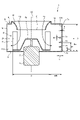
- FIG. 2 is a cross-sectional view of the centrifugal blower 1 according to the first embodiment.
- the centrifugal blower 1 has an impeller 2, a motor 3 for rotationally driving the impeller 2, and a scroll casing 4 for accommodating the impeller 2.
- the centrifugal blower 1 generates an air flow by rotating the impeller 2.
- the impeller 2 is a multi-wing impeller.
- the impeller 2 is attached to the shaft 5 of the motor 3.
- the impeller 2 rotates about the shaft 5.
- the impeller 2 has a boss portion 2a fixed to the shaft 5 and a plurality of blades 2b arranged on the peripheral edge portion of the boss portion 2a.
- the cross section shown in FIG. 2 is a cross section taken along line II-II shown in FIG. 1 and includes a rotation axis AX.
- the rotation shaft AX is the rotation center of the impeller 2.
- the axial direction is the direction of the rotation axis AX.
- the rotation direction is the direction in which the impeller 2 rotates.
- the radial direction is the direction perpendicular to the rotation axis AX.
- the scroll casing 4 has an air inlet 6 and an air outlet 7. Inside the scroll casing 4, an air flow from the suction port 6 to the air outlet 7 is generated.
- the scroll casing 4 constitutes a flow path of an air flow generated by the rotation of the impeller 2. By rotating the impeller 2, the air outside the scroll casing 4 is sucked into the inside of the scroll casing 4 through the suction port 6. By rotating the impeller 2, the air inside the scroll casing 4 is blown out of the scroll casing 4 through the outlet 7.
- FIG. 1 outside the scroll casing 4 toward the suction port 6 and an air flow Y2 from the outlet 7 to the outside of the scroll casing 4 are generated.
- a mainstream Y3 that flows from the suction port 6 through the impeller 2 and between the impeller 2 and the inner wall surface 11 of the scroll casing 4 is generated.
- the first side wall 8 and the second side wall 9 are portions of the scroll casing 4 that face each other in the axial direction, respectively.
- the outer peripheral wall 10 is a portion of the scroll casing 4 between the first side wall 8 and the second side wall 9.
- the suction port 6 is formed on the first side wall 8.
- a bell mouth 12 whose inner diameter is increased toward the outside of the scroll casing 4 is formed on the first side wall 8.
- the inner wall surface 11 is a surface of the outer peripheral wall 10 on the inner side of the scroll casing 4 and is separated from the impeller 2 in the radial direction.
- the material of the scroll casing 4 is, for example, resin.
- the scroll casing 4 has a scroll portion 13 and a diffuse portion 14.
- the scroll portion 13 is a portion constituting a spiral flow path whose width increases in the radial direction toward the downstream side of the air flow.
- the diffuser portion 14 is a portion downstream of the scroll portion 13 and constitutes a flow path between the scroll portion 13 and the air outlet 7.
- the portion of the inner wall surface 11 included in the scroll portion 13 is referred to as the inner wall surface 11a.
- the portion of the inner wall surface 11 included in the diffuse portion 14 is referred to as the inner wall surface 11b.
- the inner wall surface 11a is curved so that the distance between the outer edge 2c of the impeller 2 and the inner wall surface 11a becomes longer toward the rotation direction.
- the inner wall surface 11a is a spiral curve that moves away from the rotation axis AX as it goes in the rotation direction.
- the helix is, for example, an Archimedes logarithmic spiral. The details of the Archimedes logarithmic spiral will be described later.
- the position of the downstream end of the inner wall surface 11a is also the position of the upstream end of the inner wall surface 11b.
- the inner wall surface 11b is a flat surface.
- the diffuser portion 14 efficiently converts the dynamic pressure of the mainstream Y3 blown out from the impeller 2 into static pressure, and guides the mainstream Y3 to the outlet 7.
- the scroll casing 4 is formed with a tongue portion 15 having a shape protruding toward the inside of the scroll casing 4.
- the tongue portion 15 guides an air flow swirling inside the scroll casing 4 to the outlet 7.
- the inner wall surface 11 is provided with a plate-shaped protrusion 16 that protrudes from the inner wall surface 11 toward the impeller 2 and extends in the direction of the air flow.
- the centrifugal blower 1 according to the first embodiment is provided with three protrusions 16a, 16b, 16c having different positions in the axial direction.
- the protrusion 16 is referred to as each of the three protrusions 16a, 16b, 16c without distinction.
- Each protrusion 16 is formed so as to straddle the scroll portion 13 and the diffuse portion 14 in the scroll casing 4. That is, each protrusion 16 is formed so as to straddle the inner wall surface 11a and the inner wall surface 11b.
- the distance between the inner side surface of the scroll casing 4 of the second side wall 9 and the inner side surface of the scroll casing 4 of the first side wall 8 is defined as “A”.
- A is the length of the outlet 7 in the axial direction, and is also the height of the end 7b of the outlet 7 from the end 7a of the outlet 7 in the axial direction.
- the end 7a is the end of the outlet 7 on the side of the second side wall 9.
- the end 7b is the end of the outlet 7 on the side of the first side wall 8.
- the height of the protrusion 16 from the end 7a of the outlet 7 in the axial direction is defined as "B”.
- the height of the protrusion 16a is referred to as “Ba”
- the height of the protrusion 16b is referred to as “Bb”
- the height of the protrusion 16c is referred to as “Bc”. do.
- the protrusion length which is the distance between the edge in contact with the inner wall surface 11 and the edge on the side of the impeller 2 is defined as “C”.
- the protrusion length of the protrusion 16a is “Ca”
- the protrusion length of the protrusion 16b is “Cb”
- the protrusion length of the protrusion 16c is defined as “Cb”.
- the thickness of the protrusion 16 in the axial direction is defined as "E”.
- the thickness of the protrusion 16a is referred to as "Ea”
- the thickness of the protrusion 16b is referred to as "Eb”
- the thickness of the protrusion 16c is referred to as "Ec”. do.
- the outer diameter of the impeller 2 is set to “D”.
- the distance between the outer edge 2c of the impeller 2 and the inner wall surface 11 is defined as "WR”.
- the plate thickness of the scroll casing 4 be "F”.
- each protrusion 16 is continuously provided along the inner wall surface 11a and the inner wall surface 11b.
- Each protrusion 16 is erected in a direction perpendicular to the rotation axis AX.
- the protrusion 16a is provided at a position of a constant height "Ba" on the inner wall surface 11a and the inner wall surface 11b.
- the protrusion 16b is provided at a position of a constant height "Bb” on the inner wall surface 11a and the inner wall surface 11b.
- the protrusion 16c is provided at a position of a constant height "Bc" on the inner wall surface 11a and the inner wall surface 11b.
- the protrusion 16a is formed with a constant protrusion length "Ca”.
- the protrusion 16b is formed with a constant protrusion length "Cb”.
- the protrusion 16c is formed with a constant protrusion length "Cc”.
- the thicknesses "Ea”, “Eb” and “Ec” are equal to each other. Further, considering that the scroll casing 4 is formed by using a mold, it is desirable that the thickness “E” is about the same as the plate thickness "F" of the scroll casing 4. In the first embodiment, the thickness "E” is the same as the plate thickness "F”. As a result, each protrusion 16 can be integrally molded with the scroll casing 4. Further, in the first embodiment, the protrusion lengths “Ca”, “Cb” and “Cc” are equal to each other.
- the edge of the protrusion 16 on the impeller 2 side has a rounded shape.
- the centrifugal blower 1 has a shape in which the edge of the protrusion 16 on the side of the impeller 2 is sharper than that of the air in the vicinity of the edge of the protrusion 16 on the side of the impeller 2. The turbulence of the flow can be reduced.
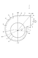
- FIG. 3 is a plan view of the centrifugal blower 1 according to the first embodiment.
- “ ⁇ ” is an angle around the rotation axis AX, and is an angle with the rotation direction of the impeller 2 as a positive direction.
- “WR ⁇ ” represents “WR” at an angle “ ⁇ ”.
- the position of the boundary between the scroll portion 13 and the diffuse portion 14 differs depending on the position of the impeller 2 or the shape of the scroll casing 4.
- the position of the air outlet 7 differs depending on the position of the impeller 2, the position of the apex of the tongue portion 15, the shape of the diffuse portion 14, and the like.
- R 0 is the radius of the helix at the reference position of the helix.
- R is the radius of the spiral at a position advanced by an angle “ ⁇ ” from the reference position in the rotation direction.
- I is the magnification of the spiral.
- the shape of the scroll casing 4 is not limited to the shape shown in FIG. 3, and can be appropriately changed.
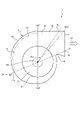
- FIG. 4 is a first diagram for explaining the relationship between the fan efficiency of the centrifugal blower 1 according to the first embodiment and the position of the protrusion 16.
- FIG. 4 shows a plan view of the centrifugal blower 1 and an example of a protrusion 16 arranged inside the scroll casing 4. In FIG. 4, the protrusion 16 is indicated by a broken line.
- the position of the end 17a on the upstream side of the air flow in the protrusion 16 can be said to be the starting point of the protrusion 16 in the rotation direction.
- the position of the end 17b on the downstream side of the air flow in the protrusion 16 can be said to be the end point of the protrusion 16 in the rotation direction.
- the position of the end 17a is referred to as a start point
- the position of the end 17b is referred to as an end point.
- ⁇ 1 is an angle formed by the virtual line N and the line connecting the start point and the rotation axis AX in the cross section of the scroll casing 4 perpendicular to the rotation axis AX.
- ⁇ 2 is an angle formed by the virtual line N and the line connecting the end point and the rotation axis AX in the cross section of the scroll casing 4 perpendicular to the rotation axis AX.
- Each of " ⁇ 1” and “ ⁇ 2" has an angle with the rotation direction of the impeller 2 as a positive direction.
- FIG. 5 is a diagram showing an example of the relationship between the fan efficiency of the centrifugal blower 1 according to the first embodiment and the starting point of the protrusion 16.
- FIG. 5 shows a solid line graph showing the relationship between the fan efficiency and “ ⁇ 1”.
- the vertical axis represents fan efficiency and the horizontal axis represents “ ⁇ 1”. From the graph shown in FIG. 5, it can be seen that the mode of change in fan efficiency when " ⁇ 1" is changed in the range of 0 ° to 330 °.
- the protrusions 16 are provided on the entire inner wall surface 11a and the inner wall surface 11b.
- the specifications of the protrusions 16 such as the number and height positions of the protrusions 16, the protrusion length of the protrusions 16, and the thickness of the protrusions 16 are as described with reference to FIGS. 1 to 3. ..
- Comparative Example 1 is a case where the scroll casing 4 is not provided with the protrusion 16. It is assumed that the scroll casing 4 in Comparative Example 1 is formed in the same manner as in the case of the first embodiment, except that the protrusion 16 is not provided.
- R2 shown by the broken line in FIG. 5 represents the fan efficiency in the case of Comparative Example 2.
- a step similar to the step disclosed in Patent Document 1 is provided in the scroll casing 4.
- the step is provided on the entire inner wall surface 11a and the inner wall surface 11b.
- the step is formed by projecting a portion of the scroll casing 4 in a height range from the end 7a of the outlet 7 to 0.50 ⁇ A toward the impeller 2.
- the portion of the scroll casing 4 having a height range from the end 7a of the outlet 7 to the position of 0.50 ⁇ A is closer to the impeller 2 by 0.095 ⁇ WR 290 ° as compared with the case of Comparative Example 1.
- the scroll casing 4 in Comparative Example 2 is formed in the same manner as in the case of the first embodiment, except that a step is provided instead of the protrusion 16.
- FIG. 5 shows an example of fan efficiency when the air volume is the same and the rotation speed is the same for the first embodiment and the comparative examples 1 and 2.
- the number of rotations is the number of times the impeller 2 rotates per unit time.
- the fan efficiency in the case of Comparative Example 1 is 43.4%.
- the fan efficiency in the case of Comparative Example 2 is 42.5%.
- the fan efficiency of the centrifugal blower 1 is higher than that of Comparative Examples 1 and 2.
- the protrusion 16 is provided at the portion where the air flows along the inner wall surface 11a, so that the rectifying effect is promoted and the fluctuation of the air flow is reduced.
- the centrifugal blower 1 can improve the fan efficiency.
- the distance between the outer edge 2c of the impeller 2 and the inner wall surface 11a is shorter than in the portion where ⁇ ⁇ 120 °.
- FIG. 6 is a second diagram for explaining the relationship between the fan efficiency of the centrifugal blower 1 and the position of the protrusion 16 according to the first embodiment.
- FIG. 6 shows a plan view of the centrifugal blower 1 and an example of a protrusion 16 arranged inside the scroll casing 4. In FIG. 6, the protrusion 16 is indicated by a broken line.
- FIG. 7 is a diagram showing an example of the relationship between the fan efficiency of the centrifugal blower 1 according to the first embodiment and the end point of the protrusion 16.
- FIG. 7 shows a solid line graph showing the relationship between the fan efficiency and “ ⁇ 2”.
- the vertical axis represents fan efficiency and the horizontal axis represents “ ⁇ 2”. From the graph shown in FIG. 7, it can be seen that the change in fan efficiency when " ⁇ 2" is changed in the range of 290 ° to 330 ° can be seen.
- the specifications of the protrusions 16 such as the number and height positions of the protrusions 16, the protrusion length of the protrusions 16, and the thickness of the protrusions 16 are as described with reference to FIGS. 1 to 3. .. “R1” and “R2” shown in FIG. 7 represent fan efficiencies in the cases of Comparative Examples 1 and 2, respectively, as in FIG.
- FIG. 7 shows an example of fan efficiency when the air volume is the same and the rotation speed of the impeller 2 is the same for the first embodiment and the comparative examples 1 and 2.
- the fan efficiency in the case of Comparative Example 1 is 43.4%.
- the fan efficiency in the case of Comparative Example 2 is 42.5%.
- the fan efficiency of the centrifugal blower 1 is higher than that of Comparative Examples 1 and 2.
- the downstream end of the protrusion 16 is at a position where the angle from the reference is 320 ° or more and 330 ° or less. That is, the protrusion 16 extends to the vicinity of the outlet 7.
- the centrifugal blower 1 can effectively guide the air flow flowing along the inner wall surface 11b to the outlet 7 by the protrusions 16 and reduce the pressure loss. Thereby, the centrifugal blower 1 can improve the fan efficiency.
- the centrifugal blower 1 has high fan efficiency because the start point of the protrusion 16 satisfies 120 ° ⁇ ⁇ 1 ⁇ 300 ° and the end point of the protrusion 16 is at the position of 320 ° ⁇ ⁇ 2 ⁇ 330 °. Can be obtained. Further, when the end point of the protrusion 16 is the position of the outlet 7, the bending or deformation of the outer peripheral wall 10 at the time of molding the scroll casing 4 can be reduced. As an example, when the scroll casing 4 is produced by using a mold having a slide mechanism, the bending or deformation of the outer peripheral wall 10 can be effectively reduced.
- FIGS. 8 to 22 show the distribution of pressure fluctuations on the inner wall surfaces 11a and 11b and the state of streamlines representing the air flow.
- the distribution of the pressure fluctuation is obtained by calculating the effective value of the pressure fluctuation from 14 Hz to 10000 Hz based on the time series data of the pressure obtained by the fluid analysis, and the distribution of the effective value of the pressure fluctuation is shown in the table. It was done.
- the distribution of pressure fluctuations in the regions of the inner wall surfaces 11a and 11b near the outlet 7 is represented by black painting, hatching of diagonal lines, dot patterns, and white outlines.
- the black-painted area is the area where the pressure fluctuation is the largest among the areas near the outlet 7 among the inner wall surfaces 11a and 11b.
- the magnitude of the pressure fluctuation decreases in the order of the black-painted area, the hatched area with diagonal lines, the dot pattern area, and the white area.
- the effective value of the pressure fluctuation in the black-painted area shall be 50 Pa or more.
- the effective value of the pressure fluctuation in the white area is 30 Pa or less.
- the unsteadiness of the air flow is high not only in the vicinity of the outlet 7 but also in the vicinity of the tongue portion 15. Significant pressure fluctuations also occur in the tongue portion 15. However, it is considered that the pressure fluctuation in the tongue portion 15 is not affected by the provision of the protrusion portion 16. The distribution of pressure fluctuations on the tongue portion 15 is not shown.
- the results of analyzing the distribution of pressure fluctuations and the state of streamlines in the first embodiment and the results of analyzing the distribution of pressure fluctuations and the state of streamlines in Comparative Examples 1 and 2 will be described. It is assumed that the conditions for fluid analysis are the same in both the first embodiment and the first and second comparative examples.
- the conditions for fluid analysis are conditions such as air volume, rotation speed, and physical property values of air. Since the outer diameter "D" of the impeller 2 is the same in Comparative Examples 1 and 2 and the first embodiment, the comparison between the comparative examples 1 and 2 and the first embodiment is based on the same Reynolds number "Re". Is.
- the peripheral speed of the blade 2b (rotation speed of the impeller 2 per minute ⁇ ⁇ ⁇ D) ⁇ 60.
- the value of the Reynolds number "Re” is 1.52 ⁇ 105 .
- FIG. 8 is a diagram showing the distribution of pressure fluctuations in the centrifugal blower according to Comparative Example 1 of the first embodiment.
- FIG. 9 is a first diagram showing the state of streamlines in the centrifugal blower according to Comparative Example 1 of the first embodiment.
- FIG. 10 is a second diagram showing the state of streamlines in the centrifugal blower according to Comparative Example 1 of the first embodiment.
- FIG. 8 shows a view of the scroll casing 4 from a position diagonally forward of the air outlet 7, and the distribution of pressure fluctuations on the inner wall surfaces 11a and 11b.
- FIG. 9 shows a view of the scroll casing 4 from a position diagonally forward of the air outlet 7 and a streamline inside the scroll casing 4.
- FIG. 10 shows a view of the scroll casing 4 from the front of the air outlet 7 and a streamline inside the scroll casing 4.
- FIG. 10 shows a state in which streamlines are divided upward and downward from toward the inner wall surface 11a or the inner wall surface 11b. According to FIG. 10, at a height position of approximately 0.38 ⁇ A, streamlines are separated upward and downward.
- FIG. 11 is a diagram showing the distribution of pressure fluctuations in the centrifugal blower according to Comparative Example 2 of the first embodiment.
- FIG. 12 is a first diagram showing the state of streamlines in the centrifugal blower according to Comparative Example 2 of the first embodiment.
- FIG. 13 is a second diagram showing the state of streamlines in the centrifugal blower according to Comparative Example 2 of the first embodiment.
- FIG. 11 shows a view of the scroll casing 4 from a position diagonally forward of the air outlet 7, and the distribution of pressure fluctuations on the inner wall surfaces 11a and 11b.
- FIG. 12 shows a view of the scroll casing 4 from a position diagonally forward of the air outlet 7 and a streamline inside the scroll casing 4.
- FIG. 13 shows a view of the scroll casing 4 from the front of the air outlet 7 and a streamline inside the scroll casing 4.
- a step 18 is provided on the entire inner wall surface 11a and the inner wall surface 11b. That is, in the scroll casing 4, the step 18 is provided in the range of 0 ⁇ ⁇ ⁇ 330 °.
- the portion in the height range of 0 to 0.50 ⁇ A is brought closer to the impeller 2 by 0.095 ⁇ WR 290 ° as compared with the case of Comparative Example 1. ing.
- Comparative Example 2 Similar to Comparative Example 1, in Comparative Example 2, as shown in FIG. 11, the pressure fluctuation becomes large in the region straddling the inner wall surface 11a and the inner wall surface 11b. The effective value of the pressure fluctuation in the region was about 62 Pa. In Comparative Example 2, the pressure fluctuation is reduced by about 14% as compared with the case of Comparative Example 1. However, in Comparative Example 2, it was found by analysis that the region where the pressure fluctuation occurs was larger than that in Comparative Example 1. In Comparative Example 2, it becomes difficult to reduce noise because the region where the pressure fluctuation occurs becomes large.
- Comparative Example 2 since the portion in the height range of 0 to 0.50 ⁇ A is closer to the impeller 2 by 0.095 ⁇ WR 290 ° as compared with the case of Comparative Example 1, the impeller 2 The air flow from is more likely to interfere with the inner wall surfaces 11a and 11b than in the case of Comparative Example 1. Therefore, in Comparative Example 2, it is considered that the region where the pressure fluctuation occurs is larger than that in Comparative Example 1.
- the air flow from the impeller 2 is divided into an upward air flow Y4 and a downward air flow Y5.
- FIGS. 12 and 13 it can be seen that the appearance of the air flow from the impeller 2 splitting upward and downward is the same as that of Comparative Example 1 shown in FIGS. 9 and 10. Therefore, it was found by analysis that the noise caused by the air flow from the impeller 2 splitting upward and downward was not improved as compared with Comparative Example 1.
- the analysis result of the first embodiment will be described.
- the results of analyzing the distribution of pressure fluctuations and the state of streamlines for the three examples will be described.
- the embodiments of the protrusions 16 in the centrifugal blower 1 are different from each other.
- FIG. 14 is a diagram showing the distribution of pressure fluctuations in the centrifugal blower 1 according to the first embodiment of the first embodiment.
- FIG. 15 is a first diagram showing the state of streamlines in the centrifugal blower 1 according to the first embodiment of the first embodiment.
- FIG. 16 is a second diagram showing the state of streamlines in the centrifugal blower 1 according to the first embodiment of the first embodiment.
- FIG. 14 shows a view of the scroll casing 4 from a position diagonally forward of the air outlet 7, and the distribution of pressure fluctuations on the inner wall surfaces 11a and 11b.
- FIG. 15 shows a view of the scroll casing 4 from a position diagonally forward of the air outlet 7 and a streamline inside the scroll casing 4.
- FIG. 16 shows a view of the scroll casing 4 from the front of the air outlet 7 and a streamline inside the scroll casing 4.
- Example 1 in FIG. 14, the effective value of the pressure fluctuation in the region straddling the inner wall surface 11a and the inner wall surface 11b was about 43 Pa to 56 Pa. In Example 1, the pressure fluctuation is reduced by 30% or more as compared with the case of Comparative Example 1.
- Example 1 the protrusion 16 is provided in a height range including 0.30 ⁇ A to 0.50 ⁇ A in which a change in pressure fluctuation is observed in Comparative Example 1.
- the provision of the protrusion 16 facilitates the flow of air through the scroll portion 13 and the diffuse portion 14 along the inner wall surface 11a or the inner wall surface 11b.
- it is considered that the separation of the streamlines upward and downward is alleviated as compared with the cases of Comparative Examples 1 and 2 due to the rectifying effect of causing the air flows Y4 and Y5 along the inner wall surface 11a or the inner wall surface 11b. ..
- the centrifugal blower 1 can reduce the pressure fluctuation due to the air flow from the impeller 2 splitting upward and downward as compared with the comparative examples 1 and 2. As a result, the centrifugal blower 1 can reduce noise.
- Example 2 unsteady fluid analysis was performed on the configuration in which the portion of the protrusion 16a near the outlet 7 was removed. It is considered that the interference of the air flow Y5 with the protrusion 16a can be reduced by removing the portion of the protrusion 16a near the outlet 7.
- FIG. 17 is a diagram showing the distribution of pressure fluctuations in the centrifugal blower 1 according to the second embodiment of the first embodiment.
- FIG. 18 is a first diagram showing the state of streamlines in the centrifugal blower 1 according to the second embodiment of the first embodiment.
- FIG. 19 is a second diagram showing the state of streamlines in the centrifugal blower 1 according to the second embodiment of the first embodiment.
- FIG. 17 shows a view of the scroll casing 4 from a position diagonally forward of the outlet 7, and the distribution of pressure fluctuations on the inner wall surfaces 11a and 11b.
- FIG. 18 shows a view of the scroll casing 4 from a position diagonally forward of the air outlet 7 and a streamline inside the scroll casing 4.
- FIG. 19 shows a view of the scroll casing 4 from the front of the air outlet 7 and a streamline inside the scroll casing 4.
- the two protrusions 16b and 16c in the second embodiment are formed in the same manner as in the first embodiment.
- “ ⁇ 2” was set to 290 ° for one protrusion 16a. It is assumed that the protrusion 16a in the second embodiment is formed in the same manner as in the first embodiment except that the “ ⁇ 2” is set to 290 °.
- the position of the downstream end of the protrusion 16a is different from the position of the downstream end of each of the protrusions 16b and 16c. That is, the plurality of protrusions 16 in the second embodiment include the protrusions 16 having different positions on the downstream ends of the protrusions 16.
- the region where the pressure fluctuation occurs is significantly smaller than that in the first embodiment. No pressure fluctuation of 30 Pa or more has occurred between the protrusion 16b and the protrusion 16c. According to FIG. 18, the interference of the air flow Y5 with the protrusion 16a is reduced.
- the effective value of the pressure fluctuation has decreased from 56 Pa in Example 1 to 42 Pa. That is, the effective value of the pressure fluctuation was reduced by about 25% as compared with the case of Example 1. Further, the effective value of the pressure fluctuation was reduced by about 45% as compared with the case of Comparative Example 1.
- Example 2 The best fan efficiency in the analysis of Example 1 was 46.3%, whereas the fan efficiency in Example 2 was 46.0%. As described above, in Example 2, no significant decrease in fan efficiency was observed as compared with Example 1.
- FIG. 20 is a diagram showing the distribution of pressure fluctuations in the centrifugal blower 1 according to the third embodiment of the first embodiment.
- FIG. 21 is a first diagram showing the state of streamlines in the centrifugal blower 1 according to the third embodiment of the first embodiment.
- FIG. 22 is a second diagram showing the state of streamlines in the centrifugal blower 1 according to the third embodiment of the first embodiment.
- FIG. 20 shows a view of the scroll casing 4 from a position diagonally forward of the air outlet 7, and the distribution of pressure fluctuations on the inner wall surfaces 11a and 11b.
- FIG. 21 shows a view of the scroll casing 4 from a position diagonally forward of the air outlet 7 and a streamline inside the scroll casing 4.
- FIG. 22 shows a view of the scroll casing 4 from the front of the air outlet 7 and a streamline inside the scroll casing 4.
- Each of the protrusions 16a, 16b, 16c in Example 3 is the case of Example 2, except that the protrusion lengths “Ca”, “Cb”, and “Cc” are doubled as compared with the case of Example 2. It is assumed that it is formed in the same manner as.
- Example 3 the region where the pressure fluctuation is generated is smaller than that in Example 1 as in Example 2. No pressure fluctuation of 30 Pa or more has occurred between the protrusion 16b and the protrusion 16c. According to FIG. 21, the interference of the air flow Y5 with the protrusion 16a is reduced.
- the effective value of the pressure fluctuation has decreased from 56 Pa in Example 1 to 43 Pa. That is, the effective value of the pressure fluctuation was reduced by about 25% as compared with the case of Example 1. Further, the effective value of the pressure fluctuation was reduced by about 45% as compared with the case of Comparative Example 1.
- FIG. 23 is a diagram for explaining the analysis results of the effective values of the pressure fluctuations in the first, second, and third embodiments of the first embodiment and the first and second comparative examples.
- FIG. 23 shows the maximum value of the effective value of the pressure fluctuation in each of Comparative Examples 1 and 2 and Examples 1, 2 and 3.
- the pressure fluctuation is reduced as compared with Comparative Examples 1 and 2.
- the centrifugal blower 1 can reduce the noise by making the pressure fluctuation smaller than that of Comparative Examples 1 and 2.
- FIG. 24 is a diagram summarizing the configurations and analysis results of Examples 1, 2 and 3 and Comparative Examples 1 and 2 of the first embodiment.
- the number of protrusions 16, “ ⁇ 1” representing the start point of the protrusions 16, “ ⁇ 2” representing the end point of the protrusions 16, and the protrusion length “ ⁇ 2” of the protrusions 16 are shown.
- “C” is shown.
- Comparative Example 2 for the step 18, “ ⁇ 1” representing the start point, “ ⁇ 2” representing the end point, and the protrusion length “C” are shown.
- FIG. 24 shows the maximum value of the effective value of the pressure fluctuation and the fan efficiency for each of Comparative Examples 1 and 2 and Examples 1, 2 and 3.
- the “ ⁇ 2” of the protrusions 16b and 16c is 330 °
- the “ ⁇ 2” of the protrusions 16a is 290 °.
- the centrifugal blower 1 can obtain higher fan efficiency in Examples 1 and 2 than in Comparative Examples 1 and 2. That is, in the first and second embodiments, the centrifugal blower 1 can reduce noise and further improve fan efficiency.
- FIG. 25 is a diagram showing the distribution of flow velocity fluctuations in the centrifugal blower 1 according to the first embodiment.
- FIG. 25 shows a view of the scroll casing 4 from a position diagonally forward of the air outlet 7, and a distribution of effective values of flow velocity fluctuations in a cross section of the scroll casing 4.
- the cross section shown in FIG. 25 is the same as the cross section shown in FIG.
- FIG. 25 shows the distribution of the flow velocity fluctuation in the flow path including the inner wall surfaces 11a and 11b, and the distribution of the flow velocity fluctuation in the other portions is omitted.
- the conditions for the fluid analysis are the same as in the case of the fluid analysis described with reference to FIGS. 8 to 22.
- the distribution of the flow velocity fluctuation is represented by black painting, hatching of diagonal lines, dot patterns, and white outlines.
- the black-painted region is the region having the largest flow velocity fluctuation in the cross section shown in FIG. 25.
- the magnitude of the flow velocity fluctuation decreases in the order of the black-painted area, the hatched area with diagonal lines, the dot pattern area, and the white area.
- the effective value of the flow velocity fluctuation in the black-painted area shall be 3 m / s or more.
- the effective value of the flow velocity fluctuation in the white area is 0 m / s. It can be said that the black-painted area has higher unsteadiness than other areas and is likely to cause turbulence in the air flow.
- the flow velocity fluctuation occurs mainly in the height range of 0.10 ⁇ A to 0.80 ⁇ A, and in the height range of 0.30 ⁇ A to 0.70 ⁇ A. It turned out to be remarkable.
- the streamlines are separated upward and downward at the height position of 0.38 ⁇ A, and the air flows to each of the upper and lower parts, so that the flow rate is 0.10 ⁇ A to 0.80 ⁇ . It is considered that the flow velocity fluctuation always occurs in the height range of A.
- the protrusion 16 is provided in a height range of 0.10 ⁇ A to 0.80 ⁇ A, so that the rectifying effect can be enhanced and noise can be suppressed.
- the centrifugal blower 1 can reduce noise by providing the protrusions 16 at the height positions of 0.10 ⁇ A, 0.30 ⁇ A, and 0.50 ⁇ A.
- the height position where the protrusion 16 is provided may be changed as appropriate.
- the centrifugal blower 1 may be provided with at least one protrusion 16 in a height range of 0.10 ⁇ A to 0.80 ⁇ A. That is, the centrifugal blower 1 is provided with at least 10% or more and 80% or less of the length "A" of the outlet 7 in the axial direction from the end 7a on the side of the second side wall 9 of the outlet 7.
- One protrusion 16 is provided. As a result, the centrifugal blower 1 can obtain a high rectifying effect.
- the centrifugal blower 1 may be provided with at least one protrusion 16 in a height range of 0.30 ⁇ A to 0.70 ⁇ A in which the flow velocity fluctuation is remarkable. That is, the centrifugal blower 1 is provided with at least 30% or more and 70% or less of the length "A" of the outlet 7 in the axial direction from the end 7a on the side of the second side wall 9 of the outlet 7. One protrusion 16 is provided. As a result, the centrifugal blower 1 can obtain a high rectifying effect.
- the centrifugal blower 1 has a plate-shaped protrusion 16 protruding from the inner wall surface 11 toward the impeller 2 and extending in the direction of the air flow.
- the centrifugal blower 1 can obtain a high rectifying effect by providing the protrusion 16.
- the centrifugal blower 1 has the effect of being able to reduce noise.
- each of the plurality of protrusions 16 provided in the centrifugal blower 1 is provided in the same range as each other in the rotation direction. That is, the start points of each of the plurality of protrusions 16 are at the same position in the rotation direction, and the start points of each of the plurality of protrusions 16 are at the same position in the rotation direction.
- the plurality of protrusions 16 may include protrusions provided in different ranges in the rotation direction. That is, the plurality of protrusions 16 may include protrusions 16 having different start point positions in the rotation direction, or protrusions 16 having different end point positions in the rotation direction.
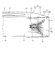
- FIG. 26 is a perspective view of the centrifugal blower 30 according to the second embodiment.
- FIG. 27 is a side view of the centrifugal blower 30 according to the second embodiment.
- FIG. 27 shows a view of the centrifugal blower 30 from the front of the outlet 7.
- the centrifugal blower 30 according to the second embodiment is provided with two protrusions 16d and 16e having different positions in the axial direction.
- the protrusion 16 is referred to without distinguishing each of the two protrusions 16d and 16e.
- the same components as those in the first embodiment are designated by the same reference numerals, and the configurations different from those in the first embodiment will be mainly described.
- the length of the protrusion 16d in the rotation direction is shorter than the length of the protrusion 16e in the rotation direction.
- the plurality of protrusions 16 having different positions in the axial direction may include the protrusions 16 provided in different ranges in the rotation direction.
- the height of the protrusion 16e from the end 7a of the air outlet 7 is defined as "Be".
- the protrusion 16e is provided at a position of a constant height "Be" in the axial direction.
- the height of the end point of the protrusion 16d from the end 7a of the air outlet 7 is defined as "Bd1”.
- the height of the starting point of the protrusion 16d from the end 7a of the air outlet 7 is defined as "Bd2".
- the start point of the protrusion 16d is higher than the end point of the protrusion 16d.
- the position of the start point in the axial direction of the protrusion 16d and the position of the end point in the axial direction of the protrusion 16d are different from each other. That is, Bd1 ⁇ Bd2.
- the protrusion 16d is provided in a height range from the position of "Bd1" to the position of "Bd2". As described above, in at least one of the protrusions 16 provided on the centrifugal blower 30, the position of the start point and the position of the end point may be different from each other in the axial direction.
- the protruding length of the protruding portion 16d is “Cd”
- the protruding length of the protruding portion 16e is “Ce”.
- “Cd” and “Ce” are different from each other.
- the plurality of protrusions 16 having different positions in the axial direction may include the protrusions 16 having different protrusion lengths.
- the thickness of the protrusion 16d in the axial direction is defined as "Ed”, and the thickness of the protrusion 16e in the axial direction is defined as “Ee”. "Ed” and “Ee” are different from each other.
- the plurality of protrusions 16 having different positions in the axial direction may include the protrusions 16 having different thicknesses in the axial direction. Further, the plurality of protrusions 16 may include protrusions 16 having a thickness different from the plate thickness “F” of the scroll casing 4.
- the protrusion length of each protrusion 16 does not have to be constant from the start point to the end point, and may be different for each position in the rotation direction.
- ⁇ WR 290 ° may be used.
- each of the plurality of protrusions 16 the range in which the protrusions 16 are provided in the rotation direction, the height range in which the protrusions 16 are provided, the protrusion length, and the thickness can be arbitrarily changed. good.
- the shape of each of the plurality of protrusions 16 can be appropriately changed according to the air volume of the centrifugal blower 30 and the like.
- the centrifugal blower 30 can obtain a high rectifying effect by appropriately determining the shape of the protrusion 16 according to the air volume and the like.
- FIG. 28 is a cross-sectional view of the centrifugal blower 40 according to the third embodiment.
- the centrifugal blower 1 according to the first embodiment is a one-sided suction type centrifugal blower having one suction port 6.
- the centrifugal blower 40 according to the third embodiment is a double suction type centrifugal blower having two suction ports 6.
- the same components as those in the first or second embodiment are designated by the same reference numerals, and the configurations different from those in the first or second embodiment will be mainly described.
- One of the two suction ports 6 is formed on the first side wall 8.
- a bell mouth 12 whose inner diameter is increased toward the outside of the scroll casing 4 is formed on the first side wall 8.
- the other of the two suction ports 6 is formed on the second side wall 9.
- a bell mouth 12 whose inner diameter is increased toward the outside of the scroll casing 4 is formed on the second side wall 9.
- the centrifugal blower 40 is provided with three protrusions 16 as in the case of the first embodiment.
- centrifugal blower 40 it is considered that pressure fluctuation occurs on the inner wall surfaces 11a and 11b as in the centrifugal blower 1 according to the first embodiment. Also in the third embodiment, the centrifugal blower 40 can reduce noise and obtain high fan efficiency by providing the protrusion 16.
- the number of protrusions 16 provided on the centrifugal blowers 1, 30 and 40 may be appropriately changed.
- the centrifugal blower 1 may be provided with one or more protrusions 16, and the number of protrusions 16 may be arbitrary.
- each of the above embodiments shows an example of the contents of the present disclosure.
- the configurations of each embodiment can be combined with other known techniques.
- the configurations of the respective embodiments may be appropriately combined. It is possible to omit or change a part of the configuration of each embodiment without departing from the gist of the present disclosure.
Landscapes
- Engineering & Computer Science (AREA)
- Mechanical Engineering (AREA)
- General Engineering & Computer Science (AREA)
- Structures Of Non-Positive Displacement Pumps (AREA)
Abstract
遠心送風機(1)は、羽根車(2)と、羽根車(2)を回転駆動するモータ(3)と、羽根車(2)を収容し、空気の吸込口(6)と空気の吹出口(7)とを有し、羽根車(2)の回転によって発生する空気流の流路を構成するスクロールケーシング(4)と、を備える。スクロールケーシング(4)のうち羽根車(2)の径方向において羽根車(2)とは離隔されている内壁面(11)には、内壁面(11)から羽根車(2)の方へ突出し、かつ空気流の方向において延ばされた板状の突起部(16)が設けられている。
Description
本開示は、スクロールケーシングを有する遠心送風機に関する。
遠心送風機は、羽根車を収容するスクロールケーシングを有する。スクロールケーシングは、空気の吸込口と空気の吹出口とを有し、羽根車の回転によって発生する空気流の流路を構成する。羽根車の回転によってスクロールケーシングの内部で発生した騒音は、吸込口または吹出口からスクロールケーシングの外へ放出される。
遠心送風機における空気の流速は、羽根車から流出した直後において最も高くなる。これに加えて、羽根車のうち径方向における外周とスクロールケーシングの内壁面との距離は、羽根車の回転方向へ進むに従って長くなる。このようなことから、従来の遠心送風機では、スクロールケーシングの内壁面上における圧力変動が大きくなり易く、内壁面から騒音が発生するという課題があった。
特許文献1には、スクロールケーシングの外周壁に、羽根車の方へせり出た段差が設けられている遠心送風機が開示されている。特許文献1の遠心送風機では、段差が設けられることによって、径方向における流路の幅が、軸方向のうち吸込口が設けられている方とは逆の側において狭められている。特許文献1の遠心送風機では、かかる構成によって吹出口における空気の流速を均一化させることで、騒音の低減が図られている。
特許文献1の技術によると、軸方向のうち吸込口が設けられている方とは逆の側にて内壁面が羽根車に近づけられているために、段差が設けられない場合と比較して、内壁面上にて圧力変動が生じる領域が広がり易い。特許文献1の技術によると、内壁面上にて圧力変動が生じる領域が広がり易いことから、騒音の低減が困難であるという問題があった。
本開示は、上記に鑑みてなされたものであって、騒音を低減可能とする遠心送風機を得ることを目的とする。
上述した課題を解決し、目的を達成するために、本開示にかかる遠心送風機は、羽根車と、羽根車を回転駆動するモータと、羽根車を収容し、空気の吸込口と空気の吹出口とを有し、羽根車の回転によって発生する空気流の流路を構成するスクロールケーシングと、を備える。スクロールケーシングのうち羽根車の径方向において羽根車とは離隔されている内壁面には、内壁面から羽根車の方へ突出し、かつ空気流の方向において延ばされた板状の突起部が設けられている。
本開示にかかる遠心送風機は、騒音を低減することができるという効果を奏する。
以下に、実施の形態にかかる遠心送風機を図面に基づいて詳細に説明する。
実施の形態1.
図1は、実施の形態1にかかる遠心送風機1の斜視図である。図2は、実施の形態1にかかる遠心送風機1の断面図である。遠心送風機1は、羽根車2と、羽根車2を回転駆動するモータ3と、羽根車2を収容するスクロールケーシング4とを有する。遠心送風機1は、羽根車2を回転させることによって空気流を発生させる。
図1は、実施の形態1にかかる遠心送風機1の斜視図である。図2は、実施の形態1にかかる遠心送風機1の断面図である。遠心送風機1は、羽根車2と、羽根車2を回転駆動するモータ3と、羽根車2を収容するスクロールケーシング4とを有する。遠心送風機1は、羽根車2を回転させることによって空気流を発生させる。
羽根車2は、多翼羽根車である。羽根車2は、モータ3のシャフト5に取り付けられている。羽根車2は、シャフト5を中心に回転する。羽根車2は、シャフト5に固定されたボス部2aと、ボス部2aの周縁部に並べられている複数の羽根2bとを有する。図2に示す断面は、図1に示すII-II線における断面であって、回転軸AXを含む断面である。回転軸AXは、羽根車2の回転中心である。以下の説明において、軸方向とは、回転軸AXの方向とする。回転方向とは、羽根車2が回転する方向とする。径方向とは、回転軸AXに垂直な方向とする。
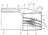
スクロールケーシング4は、空気の吸込口6と空気の吹出口7とを有する。スクロールケーシング4の内部には、吸込口6から吹出口7へ向かう空気流が発生する。スクロールケーシング4は、羽根車2の回転によって発生する空気流の流路を構成する。羽根車2を回転させることによって、スクロールケーシング4の外の空気は、吸込口6を通ってスクロールケーシング4の内部へ吸い込まれる。羽根車2を回転させることによって、スクロールケーシング4の内部の空気は、吹出口7を通ってスクロールケーシング4の外へ吹き出される。図1に示すように、スクロールケーシング4の外には、スクロールケーシング4の外から吸込口6へ向かう空気流Y1と、吹出口7からスクロールケーシング4の外へ向かう空気流Y2とが発生する。図2に示すように、スクロールケーシング4の内部には、吸込口6から羽根車2を通り、羽根車2とスクロールケーシング4の内壁面11との間へ流れる主流Y3が発生する。
第1の側壁8および第2の側壁9は、それぞれ、スクロールケーシング4のうち、軸方向において互いに向き合う部分である。外周壁10は、スクロールケーシング4のうち第1の側壁8と第2の側壁9との間の部分である。吸込口6は、第1の側壁8に形成されている。第1の側壁8には、吸込口6からスクロールケーシング4の外の方へ向かうに従って内径が拡大されたベルマウス12が形成されている。内壁面11は、外周壁10のうちスクロールケーシング4の内部側の面であって、径方向において羽根車2とは離隔されている面である。
スクロールケーシング4の材料は、例えば樹脂である。スクロールケーシング4は、スクロール部13とディフューズ部14とを有する。スクロール部13は、空気流の下流側へ向かうに従い径方向における幅が拡大している螺旋状の流路を構成する部分である。ディフューズ部14は、スクロール部13よりも下流側の部分であって、スクロール部13と吹出口7との間の流路を構成する部分である。
ここで、内壁面11のうちスクロール部13に含まれる部分を、内壁面11aとする。内壁面11のうちディフューズ部14に含まれる部分を、内壁面11bとする。スクロール部13では、回転方向へ向かうに従って、羽根車2の外縁2cと内壁面11aとの距離が長くなるように、内壁面11aが湾曲している。回転軸AXに垂直な断面において、内壁面11aは、回転方向へ向かうに従い回転軸AXから遠ざかる螺旋状の曲線である。螺旋は、例えば、アルキメデス対数螺旋である。アルキメデス対数螺旋の詳細については後述する。
内壁面11aのうち下流側の端の位置は、内壁面11bのうち上流側の端の位置でもある。内壁面11bは、平面である。ディフューズ部14は、羽根車2から吹き出された主流Y3の動圧を効率良く静圧へ変換させるとともに、吹出口7へ主流Y3を導く。
スクロールケーシング4には、スクロールケーシング4の内部の方へ張り出た形状の舌部15が形成されている。舌部15は、スクロールケーシング4の内部を旋回する空気流を吹出口7へ導く。
内壁面11には、内壁面11から羽根車2の方へ突出し、かつ空気流の方向において延ばされた板状の突起部16が設けられている。実施の形態1にかかる遠心送風機1には、軸方向における位置が互いに異なる3つの突起部16a,16b,16cが設けられている。なお、実施の形態1において、突起部16とは、3つの突起部16a,16b,16cの各々を区別せずに称したものとする。
各突起部16は、スクロールケーシング4のうち、スクロール部13とディフューズ部14とに跨って形成されている。すなわち、各突起部16は、内壁面11aと内壁面11bとに跨って形成されている。
次に、各突起部16の位置と各突起部16の形状とについて説明する。第2の側壁9のうちスクロールケーシング4の内部側の面と、第1の側壁8のうちスクロールケーシング4の内部側の面との距離を「A」とする。「A」は、軸方向における吹出口7の長さであって、軸方向における吹出口7の端7aからの吹出口7の端7bの高さでもある。端7aは、吹出口7のうち第2の側壁9の側の端である。端7bは、吹出口7のうち第1の側壁8の側の端である。
軸方向における吹出口7の端7aからの突起部16の高さを「B」とする。各突起部16の高さ「B」を区別する場合には、突起部16aの高さを「Ba」、突起部16bの高さを「Bb」、突起部16cの高さを「Bc」とする。突起部16のうち、内壁面11と接する縁と羽根車2の側の縁との距離である突出長さを「C」とする。各突起部16の突出長さ「C」を区別する場合には、突起部16aの突出長さを「Ca」、突起部16bの突出長さを「Cb」、突起部16cの突出長さを「Cc」とする。軸方向における突起部16の厚さを「E」とする。各突起部16の厚さ「E」を区別する場合には、突起部16aの厚さを「Ea」、突起部16bの厚さを「Eb」、突起部16cの厚さを「Ec」とする。また、羽根車2の外径を「D」とする。羽根車2の外縁2cと内壁面11との距離を「WR」とする。スクロールケーシング4の板厚を「F」とする。
実施の形態1において、各突起部16は、内壁面11aと内壁面11bとに沿って連続して設けられている。各突起部16は、回転軸AXに垂直な向きに立てられている。突起部16aは、内壁面11aと内壁面11bとにおいて一定の高さ「Ba」の位置に設けられている。突起部16bは、内壁面11aと内壁面11bとにおいて一定の高さ「Bb」の位置に設けられている。突起部16cは、内壁面11aと内壁面11bとにおいて一定の高さ「Bc」の位置に設けられている。突起部16aは、一定の突出長さ「Ca」で形成されている。突起部16bは、一定の突出長さ「Cb」で形成されている。突起部16cは、一定の突出長さ「Cc」で形成されている。
実施の形態1において、「Ba」は、Ba=0.10×Aを満足する。「Bb」は、Bb=0.30×Aを満足する。「Bc」は、Bc=0.50×Aを満足する。実施の形態1において、「Ba」、「Bb」および「Bc」の各々は、「A」により無次元化して表される。
実施の形態1において、各厚さ「Ea」、「Eb」および「Ec」は、互いに等しい。また、金型の使用によってスクロールケーシング4を成形することを考慮すると、厚さ「E」は、スクロールケーシング4の板厚「F」と同じ程度であることが望ましい。実施の形態1では、厚さ「E」は、板厚「F」と同じとする。これにより、各突起部16は、スクロールケーシング4と一体に成形することができる。また、実施の形態1において、各突出長さ「Ca」、「Cb」および「Cc」は、互いに等しい。
図2に示す断面において、突起部16のうち羽根車2の側の縁は、丸みを帯びた形状とされる。遠心送風機1は、図2に示す断面において、突起部16のうち羽根車2の側の縁が尖った形状である場合よりも、突起部16のうち羽根車2の側の縁の付近における空気流の乱れを少なくすることができる。
羽根車2が回転することによって、スクロールケーシング4の外の空気がベルマウス12および吸込口6を通過して、スクロールケーシング4の内部へ取り込まれる。ディフューズ部14において主流Y3の動圧は静圧へ変換されて、主流Y3は吹出口7へ向かう。吹出口7へ主流Y3が向かう際の、内壁面11a,11bの付近における主流Y3の乱れが、遠心送風機1の圧力損失の増加、および、遠心送風機1のファン効率の低下を招くことが明らかとなった。スクロールケーシング4の内部のうち吹出口7に近い領域において、主流Y3は乱れ易い。さらに、主流Y3が乱れることによって、主流Y3の流速変動が顕著となり、かつ内壁面11a,11b上に圧力変動が生じることから、内壁面11a,11bの付近における主流Y3の乱れが騒音源になり得ることが、流体解析により明らかとなった。
図3は、実施の形態1にかかる遠心送風機1の平面図である。「θ」は、回転軸AX周りの角度であって、羽根車2の回転方向を正の方向とする角度とする。スクロールケーシング4のうち回転軸AXに垂直な断面において、舌部15のうちスクロールケーシング4の内部における頂点と回転軸AXの位置とを結ぶ仮想線Nを、「θ」の基準とする。すなわち、仮想線Nは、θ=0°を表す線である。また、図3には、θ=110°を表す線と、θ=290°を表す線と、θ=330°を表す線とを示している。「WRθ」は、角度「θ」における「WR」を表す。
θ=290°の線は、スクロール部13とディフューズ部14との境界を表す。すなわち、θ=290°の線上の位置は、スクロール部13のうち下流側の端であって、かつディフューズ部14のうち上流側の端でもある。θ=290°における「WRθ」である「WR290°」は、WR290°=0.465×Dをおおよそ満足する。
羽根車2から吹き出る主流Y3は、θ=290°において多くなる。このことから、実施の形態1では、突起部16の突出長さである「C」は、「WR290°」により無次元化して表されるものとする。「C」は、C=0.095×WR290°程度であるものとする。
なお、スクロール部13とディフューズ部14との境界は、θ=290°の線上の位置に限られず、θ=290°の線上以外の位置であっても良い。スクロール部13とディフューズ部14との境界の位置は、羽根車2の位置、またはスクロールケーシング4の形状などによって異なる。
外周壁10のうちθ=330°の線上の位置は、吹出口7の位置である。すなわち、θ=330°の線上の位置は、ディフューズ部14のうち下流側の端である。なお、吹出口7の位置は、θ=330°の線上の位置に限られず、θ=330°の線上以外の位置であっても良い。吹出口7の位置は、羽根車2の位置、舌部15の頂点の位置、またはディフューズ部14の形状などによって異なる。
回転軸AXに垂直な断面における内壁面11aの形状を表すアルキメデス対数螺旋は、r=r0×exp(I×π×α÷180°)を満足する。「r0」は、螺旋の基準位置における螺旋の半径である。「r」は、基準位置から回転方向へ角度「α」だけ進んだ位置における螺旋の半径である。「I」は、螺旋の拡大率である。なお、スクロールケーシング4の形状は、図3に示す形状に限られず、適宜変更可能である。
次に、図4から図7を参照して、遠心送風機1のファン効率と、羽根車2の回転方向における突起部16の位置との関係について説明する。図4は、実施の形態1にかかる遠心送風機1のファン効率と突起部16の位置との関係について説明するための第1の図である。図4には、遠心送風機1の平面図と、スクロールケーシング4の内部に配置される突起部16の例とを示している。図4において、突起部16は破線により示している。
突起部16のうち空気流の上流側の端17aの位置は、回転方向における突起部16の始点ともいえる。突起部16のうち空気流の下流側の端17bの位置は、回転方向における突起部16の終点ともいえる。以下の説明において、端17aの位置を始点、端17bの位置を終点と称する。
「θ1」は、スクロールケーシング4のうち回転軸AXに垂直な断面において、始点と回転軸AXとを結ぶ線と仮想線Nとがなす角度である。「θ2」は、スクロールケーシング4のうち回転軸AXに垂直な断面において、終点と回転軸AXとを結ぶ線と仮想線Nとがなす角度である。「θ1」および「θ2」の各々は、羽根車2の回転方向を正の方向とする角度とする。
ここでは、ファン効率と、突起部16の始点との関係について説明する。また、図4に示すように、θ2=330°とする。すなわち、突起部16の終点は、吹出口7の位置である。なお、突起部16の始点と突起部16の終点との各々は、図4に示す位置に限定されるものではない。
図5は、実施の形態1にかかる遠心送風機1のファン効率と突起部16の始点との関係の例を示す図である。図5には、ファン効率と「θ1」との関係を表す実線のグラフを示している。図5に示すグラフにおいて、縦軸はファン効率、横軸は「θ1」を表す。図5に示すグラフから、「θ1」を0°から330°の範囲において変化させた場合におけるファン効率の変化の態様が分かる。
θ1=0°におけるファン効率は、θ=0°からθ=330°まで延ばされた突起部16が設けられている場合におけるファン効率である。この場合、回転軸AXに垂直な断面において、内壁面11aと内壁面11bとの全体に突起部16が設けられている。なお、突起部16の数と高さ位置、突起部16の突出長さ、および突起部16の厚さといった、突起部16の仕様は、図1から図3を参照して説明したとおりとする。
図5において破線により示されている「R1」は、比較例1の場合におけるファン効率を表す。比較例1は、スクロールケーシング4に突起部16が設けられない場合とした。比較例1におけるスクロールケーシング4は、突起部16が設けられていない点を除いて、実施の形態1の場合と同様に形成されているものとする。
図5において破線により示されている「R2」は、比較例2の場合におけるファン効率を表している。比較例2は、上記の特許文献1に開示されている段差と同様の段差をスクロールケーシング4に設けた場合とした。比較例2において、段差は、内壁面11aと内壁面11bとの全体に設けられている。段差は、スクロールケーシング4のうち吹出口7の端7aから0.50×Aまでの高さ範囲の部分を、羽根車2の方へせり出させることにより形成されている。スクロールケーシング4のうち吹出口7の端7aから0.50×Aの位置までの高さ範囲の部分は、比較例1の場合と比べて、0.095×WR290°だけ羽根車2へ近づけられている。比較例2におけるスクロールケーシング4は、突起部16の代わりに段差が設けられている点を除いて、実施の形態1の場合と同様に形成されているものとする。
図5には、実施の形態1と比較例1,2とについて、風量を同一とし、かつ回転数を同一とした場合におけるファン効率の例を示している。回転数は、単位時間当たりに羽根車2が回転する回数である。比較例1の場合におけるファン効率は、43.4%である。比較例2の場合におけるファン効率は、42.5%である。図5に示すグラフが「R1」および「R2」の双方を上回る「θ1」の範囲において、遠心送風機1のファン効率が比較例1および2の場合よりも高くなる。
図5によると、実施の形態1において「θ1」が120°≦θ1≦300°を満足する場合に、比較例1,2の場合よりもファン効率が高くなる。また、θ1=180°付近においてファン効率は最も高くなることが判明した。θ1=180°におけるファン効率は46.3%である。すなわち、θ1=180°の場合、比較例1よりもファン効率が2.9pt向上する。
羽根車2から流出した空気は、θ=120°の付近から内壁面11aに沿って流れる。120°≦θ1≦300°とした場合、内壁面11aに沿って空気が流れる部分に突起部16が設けられることで、整流効果が促進され、空気流の変動が低減される。これにより、遠心送風機1は、ファン効率を向上させることができる。
0°≦θ<120°の部分では、θ≧120°の部分に比べて羽根車2の外縁2cと内壁面11aとの距離が短い。θ=120°よりも上流側に突起部16が設けられると、羽根車2から流出した空気が内壁面11aに沿って流れるよりも前に突起部16に衝突することによって、圧力損失が増大し得る。圧力損失の増大によるファン効率の低下を考慮すると、θ=120°よりも上流側には突起部16を設けないこと、すなわちθ1≧120°であることが望ましい。
また、θ1>300°である場合、比較例1に対するファン効率の低下は顕著とはいえない。ただし、θ1>300°としても整流効果の促進によるファン効率向上は見込めないことが分かる。よって、θ1≦300°であることが望ましい。なお、比較例2の場合、比較例1と比べてファン効率が0.9pt低下することが分かった。遠心送風機1は、120°≦θ1≦300°を満足する突起部16が設けられることによって、高いファン効率を得ることができる。
図6は、実施の形態1にかかる遠心送風機1のファン効率と突起部16の位置との関係について説明するための第2の図である。図6には、遠心送風機1の平面図と、スクロールケーシング4の内部に配置される突起部16の一例とを示している。図6において、突起部16は破線により示している。
ここでは、ファン効率と、突起部16の終点との関係について説明する。また、図5に示す関係を踏まえて、「θ1」は180°とする。なお、突起部16の始点と突起部16の終点との各々は、図6に示す位置に限定されるものではない。
図7は、実施の形態1にかかる遠心送風機1のファン効率と突起部16の終点との関係の例を示す図である。図7には、ファン効率と「θ2」との関係を表す実線のグラフを示している。図7に示すグラフにおいて、縦軸はファン効率、横軸は「θ2」を表している。図7に示すグラフから、「θ2」を290°から330°の範囲において変化させた場合におけるファン効率の変化が分かる。
θ2=330°におけるファン効率は、θ=180°からθ=330°まで延ばされた突起部16が設けられている場合におけるファン効率を表す。なお、突起部16の数と高さ位置、突起部16の突出長さ、および突起部16の厚さといった、突起部16の仕様は、図1から図3を参照して説明したとおりとする。図7に示す「R1」、「R2」は、図5と同様に、それぞれ比較例1,2の場合におけるファン効率を表している。
図7には、実施の形態1と比較例1,2とについて、風量を同一とし、かつ羽根車2の回転数を同一とした場合におけるファン効率の例を示している。比較例1の場合におけるファン効率は、43.4%である。比較例2の場合におけるファン効率は、42.5%である。図7に示すグラフが「R1」および「R2」の双方を上回る「θ2」の範囲において、遠心送風機1のファン効率が比較例1および2の場合よりも高くなる。
図7によると、実施の形態1において「θ2」が320°≦θ2≦330°を満足する場合に、比較例1および2の場合よりもファン効率が高くなる。また、θ2=330°付近においてファン効率は最も高くなることが判明した。
一般に、吹出口7の周りでは、空気流の非定常性が高くなり、空気流の乱れによる圧力損失が生じ易い。実施の形態1では、突起部16のうち下流側の端は、基準からの角度が320°以上かつ330°以下の位置にある。すなわち、吹出口7の付近まで突起部16が延ばされている。遠心送風機1は、内壁面11bに沿って流れる空気流を突起部16によって吹出口7まで効果的に誘導させ、圧力損失を低減させることができる。これにより、遠心送風機1は、ファン効率を向上させることができる。遠心送風機1は、320°≦θ2≦330°を満足する突起部16が設けられることによって、高いファン効率を得ることができる。さらに、遠心送風機1は、θ2=330°とすることで、すなわち突起部16のうち下流側の端を吹出口7の位置とすることで、高いファン効率を得ることができる。
以上により、遠心送風機1は、突起部16の始点が120°≦θ1≦300°を満足し、かつ、突起部16の終点が320°≦θ2≦330°の位置であることによって、高いファン効率を得ることができる。さらに、突起部16の終点が吹出口7の位置である場合には、スクロールケーシング4の成形時における外周壁10の撓みまたは変形を低減できる。一例として、スライド機構を有する金型の使用によってスクロールケーシング4が生産される場合において、外周壁10の撓みまたは変形を効果的に低減できる。
次に、図8から図22を参照して、突起部16を設けることによる騒音の低減について説明する。圧力変動と騒音とには密接な関係があり、圧力変動が顕著である箇所が騒音の発生源となる。ここでは、圧力変動の低減を可能とする突起部16の配置について説明する。
図8から図22では、内壁面11a,11b上における圧力変動の分布と、空気流を表す流線の様子とを示している。図8から図22において、圧力変動の分布は、流体解析によって求められた圧力の時系列データを基に、14Hzから10000Hzにおける圧力変動の実効値を算出し、圧力変動の実効値の分布を表したものである。
図8から図22では、内壁面11a,11bのうち吹出口7から近い領域における圧力変動の分布を、黒塗り、斜線のハッチング、ドット模様および白抜きによって表している。黒塗りの領域は、内壁面11a,11bのうち吹出口7から近い領域の中で圧力変動が最も大きい領域である。黒塗りの領域、斜線のハッチングの領域、ドット模様の領域、および白抜きの領域の順に、圧力変動の大きさは小さくなる。黒塗りの領域における圧力変動の実効値は、50Pa以上とする。白抜きの領域における圧力変動の実効値は、30Pa以下とする。
なお、空気流の非定常性は、吹出口7の付近のみならず、舌部15の付近においても高くなる。舌部15においても、顕著な圧力変動が生じる。ただし、舌部15における圧力変動には、突起部16を設けることによる影響は及ばないと考えられる。舌部15における圧力変動の分布については、図示を省略する。
ここでは、実施の形態1における圧力変動の分布および流線の様子を解析した結果と、上記比較例1,2における圧力変動の分布および流線の様子を解析した結果とについて説明する。実施の形態1および比較例1,2において、流体解析の条件はいずれも同一であるものとする。流体解析の条件とは、風量、回転数、および空気の物性値などの条件である。比較例1,2および実施の形態1において羽根車2の外径「D」は同一であることから、比較例1,2および実施の形態1の比較は、同一のレイノルズ数「Re」による比較である。流体解析におけるレイノルズ数「Re」は、Re=(羽根2bの周速×D)÷(動粘度)の関係に基づいて算出される。ここで、羽根2bの周速=(羽根車2の1分間当たりの回転数×π×D)÷60である。レイノルズ数「Re」の値は、1.52×10⁵である。また、計算格子数を完全に同一とすることは困難であるため、突起部16を設けることによる効果を確認する際に影響を無視し得る程度の格子数の差は許容して、非定常流体解析を行うこととする。
実施の形態1の解析結果について説明する前に、比較例1,2の解析結果について説明する。図8は、実施の形態1の比較例1にかかる遠心送風機における圧力変動の分布を示す図である。図9は、実施の形態1の比較例1にかかる遠心送風機における流線の様子を示す第1の図である。図10は、実施の形態1の比較例1にかかる遠心送風機における流線の様子を示す第2の図である。図8には、吹出口7の前方斜め方向の位置からスクロールケーシング4を見た様子と、内壁面11a,11b上における圧力変動の分布を示している。図9には、吹出口7の前方斜め方向の位置からスクロールケーシング4を見た様子と、スクロールケーシング4の内部における流線とを示している。図10には、吹出口7の前方からスクロールケーシング4を見た様子と、スクロールケーシング4の内部における流線とを示している。
比較例1の場合、図8に示すように、内壁面11aと内壁面11bとに跨る領域において、圧力変動が大きくなる。当該領域における圧力変動の実効値は、約72Paであった。また、顕著な圧力変動は、おおよそ0.30×Aから0.50×Aの高さ範囲において生じることが分かった。
スクロールケーシング4の内部空間において、第1の側壁8がある方を上方、第2の側壁9がある方を下方とする。図9によると、羽根車2から出ている流線は、軸方向における中心付近から上方と下方とへ広がる。すなわち、羽根車2からの空気流は、0.30×Aから0.50×Aの高さ範囲において、上方へ向かう空気流Y4と下方へ向かう空気流Y5とに分かれている。このため、おおよそ0.30×Aから0.50×Aの高さ範囲において圧力変動が大きくなると考えられる。図10には、内壁面11aまたは内壁面11bへ向かってから上方と下方とへ流線が分かれる様子が示されている。図10によると、おおよそ0.38×Aの高さ位置において、上方と下方とへ流線が分かれる。
図11は、実施の形態1の比較例2にかかる遠心送風機における圧力変動の分布を示す図である。図12は、実施の形態1の比較例2にかかる遠心送風機における流線の様子を示す第1の図である。図13は、実施の形態1の比較例2にかかる遠心送風機における流線の様子を示す第2の図である。図11には、吹出口7の前方斜め方向の位置からスクロールケーシング4を見た様子と、内壁面11a,11b上における圧力変動の分布を示している。図12には、吹出口7の前方斜め方向の位置からスクロールケーシング4を見た様子と、スクロールケーシング4の内部における流線とを示している。図13には、吹出口7の前方からスクロールケーシング4を見た様子と、スクロールケーシング4の内部における流線とを示している。
上述するように、比較例2では、内壁面11aと内壁面11bとの全体に段差18が設けられている。すなわち、スクロールケーシング4において、0≦θ≦330°の範囲に段差18が設けられている。比較例2では、段差18が設けられることによって、0から0.50×Aの高さ範囲の部分が、比較例1の場合と比べて0.095×WR290°だけ羽根車2へ近づけられている。
比較例1と同様に比較例2でも、図11に示すように、内壁面11aと内壁面11bとに跨る領域において、圧力変動が大きくなる。当該領域における圧力変動の実効値は、約62Paであった。比較例2において、圧力変動は、比較例1の場合と比べて14%程度低下している。ただし、比較例2では、圧力変動が生じる領域が比較例1の場合よりも大きくなることが、解析によって判明した。比較例2では、圧力変動が生じる領域が大きくなることで、騒音の低減が困難となる。
比較例2では、0から0.50×Aの高さ範囲の部分が、比較例1の場合と比べて0.095×WR290°だけ羽根車2へ近づけられていることから、羽根車2からの空気流が比較例1の場合よりも内壁面11a,11bに干渉し易い。このため、比較例2では、圧力変動が生じる領域が比較例1の場合よりも大きくなると考えられる。
図12および図13に示すように、羽根車2からの空気流は、上方へ向かう空気流Y4と下方へ向かう空気流Y5とに分かれている。図12および図13によると、羽根車2からの空気流が上方と下方とへ分かれる様子は、図9および図10に示される比較例1の場合と変わりないことが分かる。よって、羽根車2からの空気流が上方と下方とへ分かれることによる騒音は比較例1と比べて改善されていないことが、解析によって判明した。
次に、実施の形態1の解析結果について説明する。ここでは、3つの実施例についての、圧力変動の分布および流線の様子を解析した結果を説明する。3つの実施例は、遠心送風機1における突起部16の態様が互いに異なる。
図14は、実施の形態1の実施例1にかかる遠心送風機1における圧力変動の分布を示す図である。図15は、実施の形態1の実施例1にかかる遠心送風機1における流線の様子を示す第1の図である。図16は、実施の形態1の実施例1にかかる遠心送風機1における流線の様子を示す第2の図である。図14には、吹出口7の前方斜め方向の位置からスクロールケーシング4を見た様子と、内壁面11a,11b上における圧力変動の分布を示している。図15には、吹出口7の前方斜め方向の位置からスクロールケーシング4を見た様子と、スクロールケーシング4の内部における流線とを示している。図16には、吹出口7の前方からスクロールケーシング4を見た様子と、スクロールケーシング4の内部における流線とを示している。
実施例1にかかる遠心送風機1には、図1および図2に示す3つの突起部16a,16b,16cが設けられている。図5に示す関係から、各突起部16a,16b,16cの「θ1」は180°とした。また、図7に示す関係から、各突起部16a,16b,16cの「θ2」は330°とした。さらに、各突起部16a,16b,16cは、Ba=0.10×A、Bb=0.30×A、Bc=0.50×A、Ea=Eb=Ec=F、Ca=Cb=Cc=0.095×WR290°を満足する。
実施例1では、図14において、内壁面11aと内壁面11bとに跨る領域における圧力変動の実効値は、43Paから56Pa程度であった。実施例1において、圧力変動は、比較例1の場合と比べて30%以上低下している。
実施例1では、比較例1において圧力変動の変化が認められている0.30×Aから0.50×Aを含む高さ範囲に突起部16が設けられている。突起部16が設けられていることによって、スクロール部13およびディフューズ部14を通る空気流は、内壁面11aまたは内壁面11bに沿って流れ易くなる。実施例1では、空気流Y4,Y5を内壁面11aまたは内壁面11bに沿わせる整流効果によって、上方と下方とへの流線の分かれが比較例1,2の場合よりも緩和されたと考えられる。
図15によると、実施例1における上方と下方とへの流線の分かれは、図9および図12に示される比較例1,2の場合ほど顕著ではないことが分かる。実施例1によると、遠心送風機1は、羽根車2からの空気流が上方と下方とへ分かれることによる圧力変動を、比較例1,2と比べて小さくすることができる。これにより、遠心送風機1は、騒音の低減が可能となる。
また、図16に示す流線の様子から、3つの突起部16a,16b,16cのうち最も下方に位置する突起部16aの付近において空気流Y5の乱れが生じている可能性があることが確認された。次に説明する実施例2では、突起部16aのうち吹出口7の付近における部分が除去された構成について、非定常流体解析を行った。突起部16aのうち吹出口7の付近における部分が除去されることによって、突起部16aへの空気流Y5の干渉を低減できると考えられる。
図17は、実施の形態1の実施例2にかかる遠心送風機1における圧力変動の分布を示す図である。図18は、実施の形態1の実施例2にかかる遠心送風機1における流線の様子を示す第1の図である。図19は、実施の形態1の実施例2にかかる遠心送風機1における流線の様子を示す第2の図である。図17には、吹出口7の前方斜め方向の位置からスクロールケーシング4を見た様子と、内壁面11a,11b上における圧力変動の分布を示している。図18には、吹出口7の前方斜め方向の位置からスクロールケーシング4を見た様子と、スクロールケーシング4の内部における流線とを示している。図19には、吹出口7の前方からスクロールケーシング4を見た様子と、スクロールケーシング4の内部における流線とを示している。
実施例2における2つの突起部16b,16cは、実施例1の場合と同様に形成されている。実施例2では、1つの突起部16aについては、「θ2」を290°とした。実施例2における突起部16aは、「θ2」を290°とした点を除いて、実施例1の場合と同様に形成されているものとする。このように、実施例2では、突起部16aにおける下流側の端の位置は、各突起部16b,16cにおける下流側の端の位置とは異なる。すなわち、実施例2における複数の突起部16は、突起部16のうち下流側の端の位置が互いに異なる突起部16同士を含む。
図17によると、実施例2では、圧力変動が発生している領域は、実施例1の場合よりも大幅に小さくなっている。突起部16bと突起部16cとの間では、30Pa以上の圧力変動は生じていない。図18によると、突起部16aへの空気流Y5の干渉が低減されている。圧力変動の実効値は、実施例1における56Paから、42Paへ低下している。すなわち、圧力変動の実効値は、実施例1の場合と比べて約25%低下した。また、圧力変動の実効値は、比較例1の場合と比べて約45%低下した。
実施例1の解析において最良のファン効率は46.3%であったのに対し、実施例2におけるファン効率は46.0%であった。このように、実施例2では、実施例1と比べてファン効率の大幅な低下は見られなかった。
実施例3では、実施例2の場合よりも各突起部16a,16b,16cの突出長さが長くされた構成について、非定常流体解析を行った。図20は、実施の形態1の実施例3にかかる遠心送風機1における圧力変動の分布を示す図である。図21は、実施の形態1の実施例3にかかる遠心送風機1における流線の様子を示す第1の図である。図22は、実施の形態1の実施例3にかかる遠心送風機1における流線の様子を示す第2の図である。図20には、吹出口7の前方斜め方向の位置からスクロールケーシング4を見た様子と、内壁面11a,11b上における圧力変動の分布を示している。図21には、吹出口7の前方斜め方向の位置からスクロールケーシング4を見た様子と、スクロールケーシング4の内部における流線とを示している。図22には、吹出口7の前方からスクロールケーシング4を見た様子と、スクロールケーシング4の内部における流線とを示している。
実施例3では、各突起部16a,16b,16cの突出長さ「Ca」、「Cb」、「Cc」を、実施例2における突出長さ「Ca」、「Cb」、「Cc」の2倍とした。すなわち、実施例3において、突出長さ「Ca」、「Cb」、「Cc」は、Ca=Cb=Cc=0.190×WR290°を満足する。実施例3における各突起部16a,16b,16cは、突出長さ「Ca」、「Cb」、「Cc」を実施例2の場合に対し2倍とした点を除いて、実施例2の場合と同様に形成されているものとする。
図20によると、実施例3では、実施例2と同様に、圧力変動が発生している領域は、実施例1の場合よりも小さい。突起部16bと突起部16cとの間では、30Pa以上の圧力変動は生じていない。図21によると、突起部16aへの空気流Y5の干渉が低減されている。圧力変動の実効値は、実施例1における56Paから、43Paへ低下している。すなわち、圧力変動の実効値は、実施例1の場合と比べて約25%低下した。また、圧力変動の実効値は、比較例1の場合と比べて約45%低下した。このように、実施例3では、実施例2の場合よりも各突起部16a,16b,16cの突出長さ「Ca」、「Cb」、「Cc」が長い場合であっても、圧力変動の大きさについて実施例2からの変化は見られなかった。
ただし、内壁面11a,11bからの各突起部16a,16b,16cの突出が大きすぎると、羽根車2からの空気流が各突起部16a,16b,16cに衝突し易くなると考えられる。図21によると、空気流Y4と空気流Y5とは、実施例2の場合と比べて内壁面11aまたは内壁面11bから離れた位置において上下に分かれていることが分かる。内壁面11aまたは内壁面11bから離れた位置において空気流Y4,Y5が上下に分かれることで、内壁面11aまたは内壁面11bに沿わせる整流効果が低減されることが考えられる。実施例3におけるファン効率は41.7%であった。このように、実施例3では、実施例1,2の場合よりもファン効率が低下することが分かった。
図23は、実施の形態1の実施例1,2,3と比較例1,2とにおける圧力変動の実効値の解析結果について説明するための図である。図23では、比較例1,2、および実施例1,2,3の各々における、圧力変動の実効値の最大値を表している。実施例1,2,3では、比較例1,2よりも圧力変動が低減されている。実施例1,2,3によると、遠心送風機1は、比較例1,2よりも圧力変動を小さくできることによって、騒音の低減が可能となる。
図24は、実施の形態1の実施例1,2,3と比較例1,2とについて、構成と解析結果とをまとめた図である。図24では、実施例1,2,3について、突起部16の数、突起部16の始点を表す「θ1」、突起部16の終点を表す「θ2」と、突起部16の突出長さ「C」とを示している。比較例2については、段差18について、始点を表す「θ1」と、終点を表す「θ2」と、突出長さ「C」とを示している。また、図24では、比較例1,2、および実施例1,2,3の各々について、圧力変動の実効値の最大値と、ファン効率とを示している。なお、実施例2,3では、突起部16b,16cの「θ2」は330°であって、突起部16aの「θ2」は290°である。
図24に示すように、遠心送風機1は、実施例1,2において、比較例1,2よりも高いファン効率を得ることができる。すなわち、遠心送風機1は、実施例1,2において、騒音を低減でき、さらにファン効率の向上が可能となる。
図25は、実施の形態1にかかる遠心送風機1における流速変動の分布を示す図である。図25には、吹出口7の前方斜め方向の位置からスクロールケーシング4を見た様子と、スクロールケーシング4の断面における流速変動の実効値の分布とを示している。図25に示す断面は、図2に示す断面と同じである。図25に示す断面は、回転軸AXの位置とθ=290°の位置とを結ぶ直線における断面である。図25では、内壁面11a,11bを含む流路における流速変動の分布を示しており、その他の部分における流速変動の分布については省略している。流体解析の条件は、図8から図22を参照して説明した流体解析の場合と同様とする。
図25では、流速変動の分布を、黒塗り、斜線のハッチング、ドット模様および白抜きによって表している。黒塗りの領域は、図25に示す断面の中で流速変動が最も大きい領域である。黒塗りの領域、斜線のハッチングの領域、ドット模様の領域、および白抜きの領域の順に、流速変動の大きさは小さくなる。黒塗りの領域における流速変動の実効値は、3m/s以上とする。白抜きの領域における流速変動の実効値は、0m/sとする。黒塗りの領域は、他の領域と比べて非定常性が高く、空気流の乱れが生じ易い領域といえる。
図25に示す分布によると、流速変動は、主に0.10×Aから0.80×Aの高さ範囲において生じており、0.30×Aから0.70×Aの高さ範囲において顕著であることが判明した。上述するように、0.38×Aの高さ位置において上方と下方とへ流線が分かれており、上方と下方との各々へ空気が流れることによって、0.10×Aから0.80×Aの高さ範囲では流速変動が常時生じると考えられる。遠心送風機1は、0.10×Aから0.80×Aの高さ範囲に突起部16が設けられることによって、整流効果を高め、騒音の抑制が可能となる。流速変動が顕著である領域と比較すると小さい変動であるが、0.10×Aの付近でも流速変動は生じている。遠心送風機1では、0.10×Aの付近に突起部16を設けることも、整流効果を高めるには有効といえる。よって、遠心送風機1は、0.10×A、0.30×Aおよび0.50×Aの各高さ位置に突起部16が設けられることによって、騒音の低減が可能となる。
突起部16が設けられる高さ位置は、適宜変更しても良い。遠心送風機1は、0.10×Aから0.80×Aの高さ範囲に少なくとも1つの突起部16が設けられていれば良い。すなわち、遠心送風機1には、吹出口7のうち第2の側壁9の側の端7aから軸方向において、吹出口7の長さ「A」の10%以上かつ80%以下の範囲に、少なくとも1つの突起部16が設けられている。これにより、遠心送風機1は、高い整流効果を得ることができる。
遠心送風機1には、流速変動が顕著である0.30×Aから0.70×Aの高さ範囲に少なくとも1つの突起部16が設けられても良い。すなわち、遠心送風機1には、吹出口7のうち第2の側壁9の側の端7aから軸方向において、吹出口7の長さ「A」の30%以上かつ70%以下の範囲に、少なくとも1つの突起部16が設けられている。これにより、遠心送風機1は、高い整流効果を得ることができる。
実施の形態1によると、遠心送風機1は、内壁面11から羽根車2の方へ突出し、かつ空気流の方向において延ばされた板状の突起部16を有する。遠心送風機1は、突起部16が設けられることによって、高い整流効果を得ることができる。これにより、遠心送風機1は、騒音を低減することができるという効果を奏する。
実施の形態2.
実施の形態1では、遠心送風機1に設けられる複数の突起部16の各々は、回転方向において互いに同じ範囲に設けられている。すなわち、複数の突起部16の各々における始点は、いずれも回転方向において同じ位置であって、かつ、複数の突起部16の各々における始点は、いずれも回転方向において同じ位置である。複数の突起部16には、回転方向において互いに異なる範囲に設けられている突起部同士が含まれていても良い。すなわち、複数の突起部16は、回転方向において始点の位置が互いに異なる突起部16同士、または、回転方向において終点の位置が互いに異なる突起部16同士を含んでいても良い。
実施の形態1では、遠心送風機1に設けられる複数の突起部16の各々は、回転方向において互いに同じ範囲に設けられている。すなわち、複数の突起部16の各々における始点は、いずれも回転方向において同じ位置であって、かつ、複数の突起部16の各々における始点は、いずれも回転方向において同じ位置である。複数の突起部16には、回転方向において互いに異なる範囲に設けられている突起部同士が含まれていても良い。すなわち、複数の突起部16は、回転方向において始点の位置が互いに異なる突起部16同士、または、回転方向において終点の位置が互いに異なる突起部16同士を含んでいても良い。
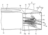
図26は、実施の形態2にかかる遠心送風機30の斜視図である。図27は、実施の形態2にかかる遠心送風機30の側面図である。図27には、吹出口7の前方から遠心送風機30を見た様子を示している。実施の形態2にかかる遠心送風機30には、軸方向における位置が互いに異なる2つの突起部16d,16eが設けられている。なお、実施の形態2において、突起部16とは、2つの突起部16d,16eの各々を区別せずに称したものとする。実施の形態2では、上記の実施の形態1と同一の構成要素には同一の符号を付し、実施の形態1とは異なる構成について主に説明する。
2つの突起部16d,16eのうち上方に設けられている突起部16eは、回転方向においてθ=180°からθ=330°までの範囲に設けられている。すなわち、突起部16eにおいて、「θ1」は180°、「θ2」は330°である。
一方、2つの突起部16d,16eのうち下方に設けられている突起部16dは、θ=180°からθ=330°までの範囲のうちの一部に設けられている。図26において、突起部16dの始点は、θ=180°の位置よりも上流側の位置である。突起部16dの終点は、θ=330°の位置である。回転方向における突起部16dの長さは、回転方向における突起部16eの長さよりも短い。このように、軸方向における位置が互いに異なる複数の突起部16には、回転方向において互いに異なる範囲に設けられている突起部16同士が含まれていても良い。
吹出口7の端7aからの突起部16eの高さを「Be」とする。突起部16eは、軸方向において一定の高さ「Be」の位置に設けられている。吹出口7の端7aからの、突起部16dの終点の高さを「Bd1」とする。吹出口7の端7aからの、突起部16dの始点の高さを「Bd2」とする。突起部16dの始点は、突起部16dの終点よりも高い位置にある。突起部16dのうち軸方向における始点の位置と、突起部16dのうち軸方向における終点の位置とは、互いに異なる。すなわち、Bd1≠Bd2である。突起部16dは、「Bd1」の位置から「Bd2」の位置までの高さ範囲に設けられている。このように、遠心送風機30に設けられる突起部16のうちの少なくとも1つでは、軸方向において、始点の位置と終点の位置とが互いに異なっていても良い。
突起部16dの突出長さを「Cd」、突起部16eの突出長さを「Ce」とする。「Cd」と「Ce」とは、互いに異なる。このように、軸方向における位置が互いに異なる複数の突起部16には、突出長さが互いに異なる突起部16同士が含まれていても良い。
軸方向における突起部16dの厚さを「Ed」、軸方向における突起部16eの厚さを「Ee」とする。「Ed」と「Ee」とは、互いに異なる。このように、軸方向における位置が互いに異なる複数の突起部16には、軸方向における厚さが互いに異なる突起部16同士が含まれていても良い。さらに、複数の突起部16には、スクロールケーシング4の板厚「F」とは異なる厚さの突起部16が含まれていても良い。
各突起部16の突出長さは、始点から終点までにおいて一定でなくても良く、回転方向における位置ごとに異なっていても良い。例えば、ある突起部16において、θ=180°の位置における突出長さ「C」は0.075×WR290°であって、θ=290°の位置における突出長さ「C」は0.095×WR290°であっても良い。さらに、θ=180°の位置からθ=290°の位置まで回転方向へ進むに従って突出長さ「C」が漸次長くなるようにしても良い。すなわち、少なくとも1つの突起部16では、突起部16のうち上流側の端から突起部16のうち下流側の端へ向かうに従って突出長さ「C」が漸次変化していても良い。
このように、複数の突起部16の各々において、回転方向において突起部16が設けられる範囲と、突起部16が設けられる高さ範囲と、突出長さと、厚さとは、任意に変更しても良い。複数の突起部16の各々の形状は、遠心送風機30の風量等に応じて適宜変更可能である。遠心送風機30は、風量等に応じて突起部16の形状が適宜決定されることによって、高い整流効果を得ることができる。
実施の形態3.
図28は、実施の形態3にかかる遠心送風機40の断面図である。実施の形態1にかかる遠心送風機1は、吸込口6が1つである片吸込型の遠心送風機である。実施の形態3にかかる遠心送風機40は、吸込口6が2つである両吸込型の遠心送風機である。実施の形態3では、上記の実施の形態1または2と同一の構成要素には同一の符号を付し、実施の形態1または2とは異なる構成について主に説明する。
図28は、実施の形態3にかかる遠心送風機40の断面図である。実施の形態1にかかる遠心送風機1は、吸込口6が1つである片吸込型の遠心送風機である。実施の形態3にかかる遠心送風機40は、吸込口6が2つである両吸込型の遠心送風機である。実施の形態3では、上記の実施の形態1または2と同一の構成要素には同一の符号を付し、実施の形態1または2とは異なる構成について主に説明する。
2つの吸込口6のうちの一方は、第1の側壁8に形成されている。第1の側壁8には、吸込口6からスクロールケーシング4の外の方へ向かうに従って内径が拡大されたベルマウス12が形成されている。2つの吸込口6のうちの他方は、第2の側壁9に形成されている。第2の側壁9には、吸込口6からスクロールケーシング4の外の方へ向かうに従って内径が拡大されたベルマウス12が形成されている。遠心送風機40には、実施の形態1の場合と同様に、3つの突起部16が設けられている。
遠心送風機40において、内壁面11a,11b上には、実施の形態1にかかる遠心送風機1と同様に、圧力変動が生じると考えられる。実施の形態3においても、遠心送風機40は、突起部16が設けられることによって、騒音を低減でき、かつ高いファン効率を得ることができる。
実施の形態1から3において、遠心送風機1,30,40に設けられる突起部16の数は、適宜変更しても良い。遠心送風機1には、1つまたは複数の突起部16が設けられていれば良く、突起部16の数は任意であるものとする。
以上の各実施の形態に示した構成は、本開示の内容の一例を示すものである。各実施の形態の構成は、別の公知の技術と組み合わせることが可能である。各実施の形態の構成同士が適宜組み合わせられても良い。本開示の要旨を逸脱しない範囲で、各実施の形態の構成の一部を省略または変更することが可能である。
1,30,40 遠心送風機、2 羽根車、2a ボス部、2b 羽根、2c 外縁、3 モータ、4 スクロールケーシング、5 シャフト、6 吸込口、7 吹出口、7a,7b,17a,17b 端、8 第1の側壁、9 第2の側壁、10 外周壁、11,11a,11b 内壁面、12 ベルマウス、13 スクロール部、14 ディフューズ部、15 舌部、16,16a,16b,16c,16d,16e 突起部、18 段差、AX 回転軸、N 仮想線、Y1,Y2,Y4,Y5 空気流、Y3 主流。
Claims (13)
- 羽根車と、
前記羽根車を回転駆動するモータと、
前記羽根車を収容し、空気の吸込口と空気の吹出口とを有し、前記羽根車の回転によって発生する空気流の流路を構成するスクロールケーシングと、を備え、
前記スクロールケーシングのうち前記羽根車の径方向において前記羽根車とは離隔されている内壁面には、前記内壁面から前記羽根車の方へ突出し、かつ前記空気流の方向において延ばされた板状の突起部が設けられていることを特徴とする遠心送風機。 - 前記スクロールケーシングは、前記空気流の下流側へ向かうに従い前記径方向における幅が拡大している螺旋状の流路を構成する部分であるスクロール部と、前記吹出口と前記スクロール部との間の流路を構成する部分であるディフューズ部とを有し、
前記突起部は、前記スクロール部と前記ディフューズ部とを合わせた部分のうちの少なくとも一部に設けられていることを特徴とする請求項1に記載の遠心送風機。 - 前記スクロールケーシングには、前記スクロールケーシングの内部の方へ張り出た形状であって、前記スクロールケーシングの内部を旋回する前記空気流を前記吹出口へ導く舌部が形成されており、
前記スクロールケーシングのうち前記羽根車の回転軸に垂直な断面において、前記舌部のうち前記スクロールケーシングの内部における頂点と前記回転軸の位置とを結ぶ線を前記羽根車の回転方向における角度の基準として、前記突起部のうち上流側の端は、前記基準からの角度が120°以上かつ300°以下の位置にあることを特徴とする請求項2に記載の遠心送風機。 - 前記突起部のうち下流側の端は、前記基準からの角度が320°以上かつ330°以下の位置にあることを特徴とする請求項3に記載の遠心送風機。
- 前記突起部のうち下流側の端は、前記吹出口の位置にあることを特徴とする請求項3または4に記載の遠心送風機。
- 前記羽根車の軸方向における前記突起部の厚さは、前記スクロールケーシングの板厚と同じであることを特徴とする請求項1から5のいずれか1つに記載の遠心送風機。
- 前記羽根車の軸方向における位置が互いに異なる複数の前記突起部を備えることを特徴とする請求項1から6のいずれか1つに記載の遠心送風機。
- 1つの前記突起部、または、前記羽根車の軸方向における位置が互いに異なる複数の前記突起部を備え、
前記スクロールケーシングは、前記吸込口が設けられている第1の側壁と、前記羽根車の軸方向において前記第1の側壁と向き合う第2の側壁と、を有し、
前記吹出口のうち前記第2の側壁の側の端から前記軸方向において、前記軸方向における前記吹出口の長さの10%以上かつ80%以下の範囲に、少なくとも1つの前記突起部が設けられていることを特徴とする請求項1から6のいずれか1つに記載の遠心送風機。 - 前記吹出口のうち前記第2の側壁の側の端から前記軸方向において、前記軸方向における前記吹出口の長さの30%以上かつ70%以下の範囲に、少なくとも1つの前記突起部が設けられていることを特徴とする請求項8に記載の遠心送風機。
- 前記羽根車の軸方向における位置が互いに異なる複数の前記突起部を備え、
複数の前記突起部は、前記羽根車の回転方向において、前記突起部のうち上流側の端の位置が互いに異なる突起部同士、または、前記回転方向において、前記突起部のうち下流側の端の位置が互いに異なる突起部同士を含むことを特徴とする請求項1から6のいずれか1つに記載の遠心送風機。 - 前記羽根車の軸方向における位置が互いに異なる複数の前記突起部を備え、
複数の前記突起部は、前記羽根車の軸方向における前記突起部の厚さが互いに異なる突起部同士を含むことを特徴とする請求項1から6のいずれか1つに記載の遠心送風機。 - 1つの前記突起部、または、前記羽根車の軸方向における位置が互いに異なる複数の前記突起部を備え、
少なくとも1つの前記突起部では、前記羽根車の軸方向において、前記突起部のうち上流側の端の位置と前記突起部のうち下流側の端の位置とが互いに異なることを特徴とする請求項1から6のいずれか1つに記載の遠心送風機。 - 1つの前記突起部、または、前記羽根車の軸方向における位置が互いに異なる複数の前記突起部を備え、
少なくとも1つの前記突起部では、前記内壁面に垂直な方向における前記突起部の長さが、前記突起部のうち上流側の端から前記突起部のうち下流側の端へ向かうに従って漸次変化していることを特徴とする請求項1から6のいずれか1つに記載の遠心送風機。
Priority Applications (3)
| Application Number | Priority Date | Filing Date | Title |
|---|---|---|---|
| CN202080105801.8A CN116261629A (zh) | 2020-11-06 | 2020-11-06 | 离心送风机 |
| PCT/JP2020/041503 WO2022097265A1 (ja) | 2020-11-06 | 2020-11-06 | 遠心送風機 |
| JP2022560595A JP7387027B2 (ja) | 2020-11-06 | 2020-11-06 | 遠心送風機 |
Applications Claiming Priority (1)
| Application Number | Priority Date | Filing Date | Title |
|---|---|---|---|
| PCT/JP2020/041503 WO2022097265A1 (ja) | 2020-11-06 | 2020-11-06 | 遠心送風機 |
Publications (1)
| Publication Number | Publication Date |
|---|---|
| WO2022097265A1 true WO2022097265A1 (ja) | 2022-05-12 |
Family
ID=81457059
Family Applications (1)
| Application Number | Title | Priority Date | Filing Date |
|---|---|---|---|
| PCT/JP2020/041503 Ceased WO2022097265A1 (ja) | 2020-11-06 | 2020-11-06 | 遠心送風機 |
Country Status (3)
| Country | Link |
|---|---|
| JP (1) | JP7387027B2 (ja) |
| CN (1) | CN116261629A (ja) |
| WO (1) | WO2022097265A1 (ja) |
Families Citing this family (2)
| Publication number | Priority date | Publication date | Assignee | Title |
|---|---|---|---|---|
| KR102804616B1 (ko) * | 2023-12-28 | 2025-05-09 | 주식회사 금성풍력 | 와류저감구조를 갖는 원심형 송풍기 하우징 |
| CN119957561A (zh) * | 2025-04-09 | 2025-05-09 | 美诗儿(浙江)环境智能电器有限公司 | 基于复合风道协同降噪的大风量低噪送风装置 |
Citations (4)
| Publication number | Priority date | Publication date | Assignee | Title |
|---|---|---|---|---|
| JP2003227491A (ja) * | 2002-01-31 | 2003-08-15 | Toshiba Corp | ファン装置を有する電子機器 |
| JP2010229871A (ja) * | 2009-03-26 | 2010-10-14 | Mitsubishi Heavy Ind Ltd | 遠心ファン及び車両用空調装置 |
| WO2018128766A1 (en) * | 2017-01-04 | 2018-07-12 | Air Distribution Technologies Ip, Llc | Blower housing with fluted outlet |
| JP2019203418A (ja) * | 2018-05-22 | 2019-11-28 | サンデン・オートモーティブクライメイトシステム株式会社 | 送風機 |
Family Cites Families (6)
| Publication number | Priority date | Publication date | Assignee | Title |
|---|---|---|---|---|
| JP2515728Y2 (ja) * | 1990-07-31 | 1996-10-30 | アイシン精機株式会社 | 内燃機関用ウオーターポンプ |
| FR2800931B1 (fr) * | 1999-11-09 | 2004-01-23 | Alstom | Dispositif de ventilation et moteur electrique de traction ferroviaire equipe d'un tel dispositif |
| KR200442465Y1 (ko) * | 2007-09-12 | 2008-11-10 | 주식회사 두원공조 | 차량용 공조 유니트의 벤트 도어 |
| CN205641400U (zh) * | 2016-05-11 | 2016-10-12 | 广东美的制冷设备有限公司 | 空调器的风道组件及空调器 |
| SG10201707225UA (en) * | 2016-09-23 | 2018-04-27 | Sulzer Management Ag | Centrifugal pump for conveying a fluid |
| CN210832225U (zh) * | 2019-11-21 | 2020-06-23 | 广东美的制冷设备有限公司 | 空调室内机及空调器 |
-
2020
- 2020-11-06 CN CN202080105801.8A patent/CN116261629A/zh active Pending
- 2020-11-06 JP JP2022560595A patent/JP7387027B2/ja active Active
- 2020-11-06 WO PCT/JP2020/041503 patent/WO2022097265A1/ja not_active Ceased
Patent Citations (4)
| Publication number | Priority date | Publication date | Assignee | Title |
|---|---|---|---|---|
| JP2003227491A (ja) * | 2002-01-31 | 2003-08-15 | Toshiba Corp | ファン装置を有する電子機器 |
| JP2010229871A (ja) * | 2009-03-26 | 2010-10-14 | Mitsubishi Heavy Ind Ltd | 遠心ファン及び車両用空調装置 |
| WO2018128766A1 (en) * | 2017-01-04 | 2018-07-12 | Air Distribution Technologies Ip, Llc | Blower housing with fluted outlet |
| JP2019203418A (ja) * | 2018-05-22 | 2019-11-28 | サンデン・オートモーティブクライメイトシステム株式会社 | 送風機 |
Also Published As
| Publication number | Publication date |
|---|---|
| CN116261629A (zh) | 2023-06-13 |
| JPWO2022097265A1 (ja) | 2022-05-12 |
| JP7387027B2 (ja) | 2023-11-27 |
Similar Documents
| Publication | Publication Date | Title |
|---|---|---|
| JP4400686B2 (ja) | プロペラファン | |
| JP5737666B2 (ja) | 遠心式送風機または斜流送風機に用いられるインペラ | |
| JP5804348B2 (ja) | 遠心式送風機または斜流送風機に用いられるインペラ | |
| US20100189557A1 (en) | Impeller and fan | |
| JP2011089460A (ja) | ターボ型流体機械 | |
| CN206346936U (zh) | 离心式风扇 | |
| KR101252984B1 (ko) | 고속 원심 펌프용 유동 벡터 제어기 | |
| CN111577655B (zh) | 叶片及使用其的轴流叶轮 | |
| WO2015087909A1 (ja) | 遠心ファン | |
| CN101014772A (zh) | 多叶片风扇 | |
| JP5473497B2 (ja) | 多翼遠心ファンおよびそれを用いた空気調和機 | |
| WO2022097265A1 (ja) | 遠心送風機 | |
| CN100451349C (zh) | 多叶片送风机的叶轮以及具有该叶轮的多叶片送风机 | |
| JP2008138536A (ja) | 遠心送風機 | |
| JP2001032794A (ja) | 遠心ファン | |
| JP2009275524A (ja) | 軸流送風機 | |
| CN110939603A (zh) | 叶片及使用其的轴流叶轮 | |
| CN104781561A (zh) | 离心式风扇 | |
| JP5291382B2 (ja) | 多翼遠心ファン | |
| JP2006125229A (ja) | シロッコファン | |
| CN101208523B (zh) | 离心式多叶片风机 | |
| JP2010242597A (ja) | 軸流送風機及び空気調和機 | |
| CN222797760U (zh) | 一种叶轮、风机及油烟机 | |
| JP2000009083A (ja) | 羽根車 | |
| JP6265843B2 (ja) | 換気送風機 |
Legal Events
| Date | Code | Title | Description |
|---|---|---|---|
| 121 | Ep: the epo has been informed by wipo that ep was designated in this application |
Ref document number: 20960818 Country of ref document: EP Kind code of ref document: A1 |
|
| ENP | Entry into the national phase |
Ref document number: 2022560595 Country of ref document: JP Kind code of ref document: A |
|
| NENP | Non-entry into the national phase |
Ref country code: DE |
|
| 122 | Ep: pct application non-entry in european phase |
Ref document number: 20960818 Country of ref document: EP Kind code of ref document: A1 |