WO2022097201A1 - Appareil à cycle de réfrigération - Google Patents
Appareil à cycle de réfrigération Download PDFInfo
- Publication number
- WO2022097201A1 WO2022097201A1 PCT/JP2020/041211 JP2020041211W WO2022097201A1 WO 2022097201 A1 WO2022097201 A1 WO 2022097201A1 JP 2020041211 W JP2020041211 W JP 2020041211W WO 2022097201 A1 WO2022097201 A1 WO 2022097201A1
- Authority
- WO
- WIPO (PCT)
- Prior art keywords
- refrigerant
- oil
- heat exchanger
- decompression
- compressor
- Prior art date
Links
- 238000005057 refrigeration Methods 0.000 title claims abstract description 60
- 239000003507 refrigerant Substances 0.000 claims abstract description 261
- 238000011084 recovery Methods 0.000 claims abstract description 83
- 239000003921 oil Substances 0.000 claims description 266
- 230000006837 decompression Effects 0.000 claims description 166
- 239000010721 machine oil Substances 0.000 claims description 89
- 230000001603 reducing effect Effects 0.000 description 122
- 238000000926 separation method Methods 0.000 description 36
- 230000006870 function Effects 0.000 description 26
- 239000007788 liquid Substances 0.000 description 26
- 238000001704 evaporation Methods 0.000 description 21
- 230000008020 evaporation Effects 0.000 description 21
- 238000010586 diagram Methods 0.000 description 15
- 238000004090 dissolution Methods 0.000 description 12
- 229920006395 saturated elastomer Polymers 0.000 description 11
- 238000009833 condensation Methods 0.000 description 8
- 238000001514 detection method Methods 0.000 description 8
- 230000005494 condensation Effects 0.000 description 7
- 230000008859 change Effects 0.000 description 6
- 230000004048 modification Effects 0.000 description 6
- 238000012986 modification Methods 0.000 description 6
- 230000000694 effects Effects 0.000 description 5
- 238000000034 method Methods 0.000 description 3
- 230000007704 transition Effects 0.000 description 3
- QGZKDVFQNNGYKY-UHFFFAOYSA-N Ammonia Chemical compound N QGZKDVFQNNGYKY-UHFFFAOYSA-N 0.000 description 2
- CURLTUGMZLYLDI-UHFFFAOYSA-N Carbon dioxide Chemical compound O=C=O CURLTUGMZLYLDI-UHFFFAOYSA-N 0.000 description 2
- ATUOYWHBWRKTHZ-UHFFFAOYSA-N Propane Chemical compound CCC ATUOYWHBWRKTHZ-UHFFFAOYSA-N 0.000 description 2
- 230000007423 decrease Effects 0.000 description 2
- 230000008569 process Effects 0.000 description 2
- 238000011144 upstream manufacturing Methods 0.000 description 2
- 230000009471 action Effects 0.000 description 1
- 229910021529 ammonia Inorganic materials 0.000 description 1
- 229910002092 carbon dioxide Inorganic materials 0.000 description 1
- 239000001569 carbon dioxide Substances 0.000 description 1
- 238000001816 cooling Methods 0.000 description 1
- 230000003247 decreasing effect Effects 0.000 description 1
- 230000006866 deterioration Effects 0.000 description 1
- 238000007599 discharging Methods 0.000 description 1
- 238000002347 injection Methods 0.000 description 1
- 239000007924 injection Substances 0.000 description 1
- JEIPFZHSYJVQDO-UHFFFAOYSA-N iron(III) oxide Inorganic materials O=[Fe]O[Fe]=O JEIPFZHSYJVQDO-UHFFFAOYSA-N 0.000 description 1
- 230000001050 lubricating effect Effects 0.000 description 1
- 238000013021 overheating Methods 0.000 description 1
- 230000003449 preventive effect Effects 0.000 description 1
- 239000001294 propane Substances 0.000 description 1
- 230000009467 reduction Effects 0.000 description 1
- 239000011555 saturated liquid Substances 0.000 description 1
- 238000007789 sealing Methods 0.000 description 1
- 239000007787 solid Substances 0.000 description 1
Images


Classifications
-
- F—MECHANICAL ENGINEERING; LIGHTING; HEATING; WEAPONS; BLASTING
- F25—REFRIGERATION OR COOLING; COMBINED HEATING AND REFRIGERATION SYSTEMS; HEAT PUMP SYSTEMS; MANUFACTURE OR STORAGE OF ICE; LIQUEFACTION SOLIDIFICATION OF GASES
- F25B—REFRIGERATION MACHINES, PLANTS OR SYSTEMS; COMBINED HEATING AND REFRIGERATION SYSTEMS; HEAT PUMP SYSTEMS
- F25B13/00—Compression machines, plants or systems, with reversible cycle
-
- F—MECHANICAL ENGINEERING; LIGHTING; HEATING; WEAPONS; BLASTING
- F25—REFRIGERATION OR COOLING; COMBINED HEATING AND REFRIGERATION SYSTEMS; HEAT PUMP SYSTEMS; MANUFACTURE OR STORAGE OF ICE; LIQUEFACTION SOLIDIFICATION OF GASES
- F25B—REFRIGERATION MACHINES, PLANTS OR SYSTEMS; COMBINED HEATING AND REFRIGERATION SYSTEMS; HEAT PUMP SYSTEMS
- F25B31/00—Compressor arrangements
- F25B31/002—Lubrication
- F25B31/004—Lubrication oil recirculating arrangements
-
- F—MECHANICAL ENGINEERING; LIGHTING; HEATING; WEAPONS; BLASTING
- F25—REFRIGERATION OR COOLING; COMBINED HEATING AND REFRIGERATION SYSTEMS; HEAT PUMP SYSTEMS; MANUFACTURE OR STORAGE OF ICE; LIQUEFACTION SOLIDIFICATION OF GASES
- F25B—REFRIGERATION MACHINES, PLANTS OR SYSTEMS; COMBINED HEATING AND REFRIGERATION SYSTEMS; HEAT PUMP SYSTEMS
- F25B43/00—Arrangements for separating or purifying gases or liquids; Arrangements for vaporising the residuum of liquid refrigerant, e.g. by heat
- F25B43/02—Arrangements for separating or purifying gases or liquids; Arrangements for vaporising the residuum of liquid refrigerant, e.g. by heat for separating lubricants from the refrigerant
-
- F—MECHANICAL ENGINEERING; LIGHTING; HEATING; WEAPONS; BLASTING
- F25—REFRIGERATION OR COOLING; COMBINED HEATING AND REFRIGERATION SYSTEMS; HEAT PUMP SYSTEMS; MANUFACTURE OR STORAGE OF ICE; LIQUEFACTION SOLIDIFICATION OF GASES
- F25B—REFRIGERATION MACHINES, PLANTS OR SYSTEMS; COMBINED HEATING AND REFRIGERATION SYSTEMS; HEAT PUMP SYSTEMS
- F25B49/00—Arrangement or mounting of control or safety devices
- F25B49/02—Arrangement or mounting of control or safety devices for compression type machines, plants or systems
-
- F—MECHANICAL ENGINEERING; LIGHTING; HEATING; WEAPONS; BLASTING
- F25—REFRIGERATION OR COOLING; COMBINED HEATING AND REFRIGERATION SYSTEMS; HEAT PUMP SYSTEMS; MANUFACTURE OR STORAGE OF ICE; LIQUEFACTION SOLIDIFICATION OF GASES
- F25B—REFRIGERATION MACHINES, PLANTS OR SYSTEMS; COMBINED HEATING AND REFRIGERATION SYSTEMS; HEAT PUMP SYSTEMS
- F25B2313/00—Compression machines, plants or systems with reversible cycle not otherwise provided for
- F25B2313/027—Compression machines, plants or systems with reversible cycle not otherwise provided for characterised by the reversing means
- F25B2313/02741—Compression machines, plants or systems with reversible cycle not otherwise provided for characterised by the reversing means using one four-way valve
-
- F—MECHANICAL ENGINEERING; LIGHTING; HEATING; WEAPONS; BLASTING
- F25—REFRIGERATION OR COOLING; COMBINED HEATING AND REFRIGERATION SYSTEMS; HEAT PUMP SYSTEMS; MANUFACTURE OR STORAGE OF ICE; LIQUEFACTION SOLIDIFICATION OF GASES
- F25B—REFRIGERATION MACHINES, PLANTS OR SYSTEMS; COMBINED HEATING AND REFRIGERATION SYSTEMS; HEAT PUMP SYSTEMS
- F25B2313/00—Compression machines, plants or systems with reversible cycle not otherwise provided for
- F25B2313/031—Sensor arrangements
- F25B2313/0314—Temperature sensors near the indoor heat exchanger
-
- F—MECHANICAL ENGINEERING; LIGHTING; HEATING; WEAPONS; BLASTING
- F25—REFRIGERATION OR COOLING; COMBINED HEATING AND REFRIGERATION SYSTEMS; HEAT PUMP SYSTEMS; MANUFACTURE OR STORAGE OF ICE; LIQUEFACTION SOLIDIFICATION OF GASES
- F25B—REFRIGERATION MACHINES, PLANTS OR SYSTEMS; COMBINED HEATING AND REFRIGERATION SYSTEMS; HEAT PUMP SYSTEMS
- F25B2313/00—Compression machines, plants or systems with reversible cycle not otherwise provided for
- F25B2313/031—Sensor arrangements
- F25B2313/0315—Temperature sensors near the outdoor heat exchanger
-
- F—MECHANICAL ENGINEERING; LIGHTING; HEATING; WEAPONS; BLASTING
- F25—REFRIGERATION OR COOLING; COMBINED HEATING AND REFRIGERATION SYSTEMS; HEAT PUMP SYSTEMS; MANUFACTURE OR STORAGE OF ICE; LIQUEFACTION SOLIDIFICATION OF GASES
- F25B—REFRIGERATION MACHINES, PLANTS OR SYSTEMS; COMBINED HEATING AND REFRIGERATION SYSTEMS; HEAT PUMP SYSTEMS
- F25B2400/00—General features or devices for refrigeration machines, plants or systems, combined heating and refrigeration systems or heat-pump systems, i.e. not limited to a particular subgroup of F25B
- F25B2400/23—Separators
-
- F—MECHANICAL ENGINEERING; LIGHTING; HEATING; WEAPONS; BLASTING
- F25—REFRIGERATION OR COOLING; COMBINED HEATING AND REFRIGERATION SYSTEMS; HEAT PUMP SYSTEMS; MANUFACTURE OR STORAGE OF ICE; LIQUEFACTION SOLIDIFICATION OF GASES
- F25B—REFRIGERATION MACHINES, PLANTS OR SYSTEMS; COMBINED HEATING AND REFRIGERATION SYSTEMS; HEAT PUMP SYSTEMS
- F25B2700/00—Sensing or detecting of parameters; Sensors therefor
- F25B2700/21—Temperatures
- F25B2700/2109—Temperatures of a separator
-
- F—MECHANICAL ENGINEERING; LIGHTING; HEATING; WEAPONS; BLASTING
- F25—REFRIGERATION OR COOLING; COMBINED HEATING AND REFRIGERATION SYSTEMS; HEAT PUMP SYSTEMS; MANUFACTURE OR STORAGE OF ICE; LIQUEFACTION SOLIDIFICATION OF GASES
- F25B—REFRIGERATION MACHINES, PLANTS OR SYSTEMS; COMBINED HEATING AND REFRIGERATION SYSTEMS; HEAT PUMP SYSTEMS
- F25B2700/00—Sensing or detecting of parameters; Sensors therefor
- F25B2700/21—Temperatures
- F25B2700/2115—Temperatures of a compressor or the drive means therefor
- F25B2700/21151—Temperatures of a compressor or the drive means therefor at the suction side of the compressor
-
- F—MECHANICAL ENGINEERING; LIGHTING; HEATING; WEAPONS; BLASTING
- F25—REFRIGERATION OR COOLING; COMBINED HEATING AND REFRIGERATION SYSTEMS; HEAT PUMP SYSTEMS; MANUFACTURE OR STORAGE OF ICE; LIQUEFACTION SOLIDIFICATION OF GASES
- F25B—REFRIGERATION MACHINES, PLANTS OR SYSTEMS; COMBINED HEATING AND REFRIGERATION SYSTEMS; HEAT PUMP SYSTEMS
- F25B2700/00—Sensing or detecting of parameters; Sensors therefor
- F25B2700/21—Temperatures
- F25B2700/2115—Temperatures of a compressor or the drive means therefor
- F25B2700/21152—Temperatures of a compressor or the drive means therefor at the discharge side of the compressor
-
- F—MECHANICAL ENGINEERING; LIGHTING; HEATING; WEAPONS; BLASTING
- F25—REFRIGERATION OR COOLING; COMBINED HEATING AND REFRIGERATION SYSTEMS; HEAT PUMP SYSTEMS; MANUFACTURE OR STORAGE OF ICE; LIQUEFACTION SOLIDIFICATION OF GASES
- F25B—REFRIGERATION MACHINES, PLANTS OR SYSTEMS; COMBINED HEATING AND REFRIGERATION SYSTEMS; HEAT PUMP SYSTEMS
- F25B2700/00—Sensing or detecting of parameters; Sensors therefor
- F25B2700/21—Temperatures
- F25B2700/2117—Temperatures of an evaporator
Definitions
- This disclosure relates to a refrigeration cycle device.
- Patent Document 1 describes that the refrigerating machine oil is separated above the refrigerant in an oil separator provided on the outlet side of the condenser and returned to the compressor via a capillary tube.
- Installing the oil separator on the outlet side of the condenser rather than on the discharge side of the compressor has the effect of preventing deterioration of refrigeration cycle performance due to discharge pressure loss.
- the temperature of the refrigerant flowing into the oil separator is too high, the refrigerant and the refrigerating machine oil will not be sufficiently separated in the oil separator. In this case, the refrigerant flows out to the oil return path from the oil separator to the compressor, and the recovery efficiency of the refrigerating machine oil is lowered.
- An object of the present disclosure is to provide a refrigerating cycle apparatus capable of improving the recovery efficiency of refrigerating machine oil.
- the present disclosure is a refrigeration cycle apparatus, which is a compressor, a first heat exchanger, a second heat exchanger, a first decompression device, an oil separator, a compressor, a first heat exchanger, and oil.
- the first circulation path for circulating the refrigerant in the order of the separator, the first decompression device, and the second heat exchanger, the oil return path connecting the oil separator and the suction side of the compressor, and the oil return path are provided.
- a second decompression device and a control device for controlling the first decompression device and the second decompression device are provided, and the control device is used when the refrigerant flowing in the first circulation path and the refrigerating machine oil are separated by the oil separator.
- FIG. 1 It is a figure which shows the structure of the refrigerating cycle apparatus which concerns on Embodiment 1. (normal mode). It is a figure which shows the structure of the refrigerating cycle apparatus which concerns on Embodiment 1. (oil recovery mode). It is a graph which shows the relationship between the separation temperature of a refrigerating machine oil, and the saturation dissolution rate. It is a figure which shows the structure of the oil separator which functions as a liquid-liquid separator. It is a ph diagram which shows the state change of the refrigerant of the refrigerating cycle apparatus which concerns on Embodiment 1. FIG. It is a flowchart which shows the control which switches between a normal mode and an oil recovery mode at the time of startup.
- FIG. It is a ph diagram which shows the state change of the refrigerant of the refrigerating cycle apparatus which concerns on Embodiment 3.
- FIG. It is a figure which shows the structure of the refrigerating cycle apparatus which concerns on Embodiment 4 (oil recovery mode).
- Embodiment 1. 1 and 2 are diagrams showing the configuration of the refrigeration cycle apparatus 100 according to the first embodiment.
- the solid arrows shown in FIGS. 1 and 2 indicate the direction in which the refrigerant flows.
- the dashed arrows shown in FIGS. 1 and 2 indicate the direction in which the refrigerating machine oil flows.
- FIG. 1 shows the flow of the refrigerant and the refrigerating machine oil when the refrigerating cycle device 100 is operating in the normal mode.
- FIG. 2 shows the flow of the refrigerant and the refrigerating machine oil when the refrigerating cycle device 100 is operating in the oil recovery mode.
- the refrigerating cycle device 100 includes a refrigerant circuit 10 and a control device 80 that controls the refrigerant circuit 10.
- the refrigerant circuit 10 connects the compressor 1, the first heat exchanger 2, the oil separator 3, the first decompression device 4, the second heat exchanger 5, and the second decompression device 7.
- a refrigerant pipe 60 is provided.
- the pipe connecting between the oil separator 3 and the second decompression device 7 is referred to as an oil return pipe 61.
- FIGS. 1 are designated with reference numerals a, b, c, and d indicating the positions of the refrigerant pipes 60.
- Refrigerant such as Freon circulates in the refrigerant circuit 10.
- Ammonia, carbon dioxide, propane or the like may be used as a refrigerant other than chlorofluorocarbons.
- the first circulation path for circulating the refrigerant is the path for circulating the refrigerant in the order of the compressor 1, the first heat exchanger 2, the oil separator 3, the first decompression device 4, the second heat exchanger 5, and the compressor 1. It is configured.
- An oil return path is configured by a path from the oil separator 3 to the compressor 1 via the oil return pipe 61 and the second decompression device 7.
- the compressor 1 circulates the refrigerant in the refrigerant circuit 10 by increasing the pressure of the sucked refrigerant and then discharging the refrigerant.
- Refrigerating machine oil is sealed in the compressor 1.
- the refrigerating machine oil plays a role of lubricating action, sealing action, rust preventive action, etc. for the compressor 1.
- a first temperature sensor 51 for detecting the discharge temperature of the refrigerant is provided on the discharge side of the compressor 1.
- the first heat exchanger 2 exchanges heat between the refrigerant flowing inside the first heat exchanger 2 and the outside air.
- a high-temperature, high-pressure gas refrigerant flows into the first heat exchanger 2 from the compressor 1. Therefore, the first heat exchanger 2 functions as a condenser.
- the first heat exchanger 2 is provided with a second temperature sensor 52 that detects the condensation temperature of the refrigerant.
- the first pressure reducing device 4 is provided with a pressure reducing valve (not shown) for adjusting the degree of pressure reduction, and has a function of adjusting the opening degree of the pressure reducing valve.
- the first pressure reducing device 4 adjusts the flow rate and pressure of the refrigerant by adjusting the opening degree of the pressure reducing valve. As the opening degree of the pressure reducing valve of the first pressure reducing device 4 becomes smaller, the pressure reducing effect becomes higher.
- the second heat exchanger 5 exchanges heat between the refrigerant flowing inside the second heat exchanger 5 and the outside air.
- a low-temperature, low-pressure liquid refrigerant flows from the first decompression device 4 to the second heat exchanger 5. Therefore, the second heat exchanger 5 functions as an evaporator.
- the second heat exchanger 5 is provided with a third temperature sensor 53 that detects the evaporation temperature of the refrigerant.
- the oil separator 3 has a function of returning the refrigerating machine oil to the compressor 1 when the refrigerant and the refrigerating machine oil are separated in the oil separator 3.
- the compressor 1 discharges the high-pressure refrigerant gas
- a part of the refrigerating machine oil sealed in the compressor 1 is discharged together with the high-pressure refrigerant gas.
- An oil separator 3 is used to separate the refrigerating machine oil discharged from the compressor 1 from the refrigerant and return it to the compressor 1.
- the oil separator 3 guides the refrigerant to the first decompression device 4, while guiding the refrigerating machine oil to the second decompression device 7 via the oil return pipe 61.
- the control device 80 includes a control board 81.
- a processor 82 and a memory 83 are mounted on the control board 81.
- the processor 82 executes an operating system and application program stored in the memory 83.
- the processor 82 executes an application program and refers to various data stored in the memory 83.
- the memory 83 stores the detection values of the first temperature sensor 51, the second temperature sensor 52, and the third temperature sensor 53 provided in the refrigerant circuit 10.
- the memory 83 includes, for example, a ROM (Read Only Memory), a RAM (Random Access Memory), and a flash memory.
- the flash memory stores the operating system and application programs.
- the control device 80 determines the separation status of the refrigerant flowing through the refrigerant pipe 60 and the refrigerating machine oil based on the detection values of the first temperature sensor 51, the second temperature sensor 52, and the third temperature sensor 53. Specifically, in the control device 80, the temperature of the refrigerant in the oil separator 3 is the separation temperature of the refrigerating machine oil based on the detection values of the first temperature sensor 51, the second temperature sensor 52, and the third temperature sensor 53. Determine if it is as follows.
- the control device 80 determines that the temperature of the refrigerant in the oil separator 3 is equal to or lower than the separation temperature of the refrigerating machine oil
- the control device 80 controls the opening degree of the pressure reducing valve between the first decompression device 4 and the second decompression device 7. By doing so, the operation mode of the refrigerating cycle apparatus 100 is switched from the normal mode to the oil recovery mode. In the oil recovery mode, the refrigerating machine oil separated into the upper layer of the refrigerant in the oil separator 3 is returned to the compressor 1 via the second decompression device 7.
- FIG. 3 is a graph showing the relationship between the separation temperature of the refrigerating machine oil and the saturated dissolution rate.
- the saturated dissolution rate of the refrigerating machine oil with respect to the refrigerant is determined by the type of the refrigerant and the type of the refrigerating machine oil.
- FIG. 3 shows the relationship between the separation temperature of the refrigerating machine oil and the saturated dissolution rate when the refrigerating machine oil and the refrigerant used in the present embodiment are targeted.
- the saturated dissolution rate of the refrigerating machine oil with respect to the refrigerant decreases.
- the separation temperature with respect to the saturated dissolution rate can be obtained.
- the separation temperature of the refrigerating machine oil is specified in advance with reference to the graph shown in FIG.
- the separation temperature data is stored in the memory 83 of the control device 80.
- the control device 80 determines whether the operation mode of the refrigerating cycle device 100 is the normal mode or the oil recovery mode by using the data of the separation temperature stored in the memory 83.
- ⁇ Normal mode> The normal mode will be described with reference to FIG.
- the compressor 1, the first heat exchanger 2, the second heat exchanger 5, the first decompression device 4, and the second are set so that the discharge temperature and pressure correspond to the target capacity of the refrigeration cycle device 100.
- This mode controls the decompression device 7 and the like.
- the refrigerant circulates in the order of the compressor 1, the first heat exchanger 2, the oil separator 3, the first decompression device 4, and the second heat exchanger 5.
- control device 80 adjusts the opening degree of the pressure reducing valve of the first pressure reducing device 4 so that the discharge temperature and pressure correspond to the target capacity of the refrigerating cycle device 100.
- the control device 80 lowers the opening degree of the pressure reducing valve of the second pressure reducing device 7 so that the amount of the refrigerant flowing from the oil separator 3 into the oil return pipe 61 is reduced. As a result, the degree of decompression of the second decompression device 7 becomes high. Desirably, the control device 80 reduces the opening degree of the pressure reducing valve of the second pressure reducing device 7 so that the oil return path from the oil return pipe 61 to the compressor 1 via the second pressure reducing device 7 is blocked. That is, the opening degree of the pressure reducing valve of the second pressure reducing device 7 is set to 0%. This makes it possible to prevent the refrigerant from flowing to the compressor 1 via the oil return path.
- the opening degree of the pressure reducing valve of the second pressure reducing device 7 may be such that a part of the refrigerant can be prevented from flowing into the oil return path.
- the oil recovery mode is a mode in which the refrigerating machine oil separated into the upper layer of the refrigerant in the oil separator 3 is returned to the compressor 1 via the oil return pipe 61.
- the opening degree of the pressure reducing valve of the first pressure reducing device 4 is lower than that in the normal mode, while the opening degree of the pressure reducing valve of the second pressure reducing device 7 is higher than in the normal mode.
- the degree of decompression of the first decompression device 4 is higher than that in the normal mode, while the degree of decompression of the second decompression device 7 is lower.
- the second pressure reducing device 7 sets the opening degree of the pressure reducing valve to 100%.
- the opening degree of the pressure reducing valve of the second pressure reducing device 7 does not necessarily have to be increased to 100%, and the opening degree may be such that the inflow of refrigerating machine oil from the oil separator 3 to the oil return pipe 61 is promoted.
- the first decompression device 4 lowers the opening degree of the pressure reducing valve, so that the decompression effect of the first decompression device 4 is enhanced as compared with the normal mode.
- the temperature of the refrigerant flowing from the first heat exchanger 2 into the oil separator 3 is lowered.
- the temperature of the refrigerant mixed with the refrigerating machine oil can be more reliably lowered to the separation temperature of the refrigerating machine oil.
- the separation of the refrigerant and the refrigerating machine oil is promoted. Therefore, the recovery efficiency of the refrigerating machine oil can be improved.
- the degree of opening degree of the pressure reducing valve of the first pressure reducing device 4 in the oil recovery mode can be appropriately determined in consideration of the effect of lowering the temperature of the refrigerant.
- the inflow of the refrigerating machine oil from the oil separator 3 toward the oil return pipe 61 can be promoted, and the refrigerating machine oil is mixed. It is possible to make sure that the temperature of the refrigerant is lower than the separation temperature of the refrigerating machine oil.
- the pressure reducing device 7 may be configured by a solenoid valve that changes the oil return pipe 61 into an open state and a closed state.
- the refrigerating machine oil separated in the upper layer of the refrigerant in the oil separator 3 returns to the compressor 1 via the second decompression device 7.
- the refrigerant in the oil separator 3 is decompressed in the first decompression device 4 and flows into the second heat exchanger 5.
- the refrigerant flowing into the second heat exchanger 5 exchanges heat with the outside air and then returns to the compressor 1.
- FIG. 4 is a diagram showing the structure of an oil separator 3 that functions as a liquid-liquid separator.
- the oil separator 3 has a main body 31 in which the refrigerant and the refrigerating machine oil are stored.
- the main body 31 is provided with a first pipe 32, a second pipe 33, and a third pipe 34 that communicate with the main body 31.
- the first pipe 32 is connected to a refrigerant pipe 60 extending from the first heat exchanger 2 to the oil separator 3.
- the second pipe 33 is connected to the refrigerant pipe 60 extending from the first decompression device 4 to the oil separator 3.
- the third pipe 34 is connected to the refrigerant pipe 60 extending from the second decompression device 7 to the oil separator 3.
- the first pipe 32 is provided below the main body 31. Therefore, when the liquid refrigerant and the refrigerating machine oil flow into the main body 31 from the first pipe 32, the refrigerant and the refrigerating machine oil are separated due to the density difference between the refrigerant and the refrigerating machine oil. As a result, the boundary surface 41 between the refrigerant and the refrigerating machine oil is formed in the main body 31. The refrigerating machine oil is separated into the upper layer of the refrigerant. Since the third pipe 34 is provided above the main body 31, the refrigerating machine oil separated in the upper layer of the refrigerant can be guided to the second decompression device 7.
- the second pipe 33 is provided in the main body 31 at a position higher than that of the first pipe 32. The liquid refrigerant separated below the refrigerating machine oil is guided to the first decompression device 4 via the second pipe 33.
- FIG. 5 is a ph diagram showing a change in the state of the refrigerant of the refrigerating cycle apparatus according to the first embodiment.
- the horizontal axis of FIG. 5 shows the specific enthalpy.
- the vertical axis of FIG. 5 shows the pressure.
- L1 indicates a saturated liquid line and a saturated steam line of the refrigerant
- L2 and L3 indicate changes in the state of the refrigerant circulating in the refrigerant circuit 10.
- Reference numerals a to d indicate the states of the refrigerant at the positions of the reference numerals a to d shown in the refrigerant circuit 10 of FIG.
- the reference numerals b'and c' indicate the state of the refrigerant at the positions of the reference numerals b'and the reference numeral c'shown in the refrigerant circuit 10 of FIG.
- the refrigerating cycle apparatus 100 operates in the refrigerating cycle of reference numeral a ⁇ b ⁇ c ⁇ d ⁇ a shown in FIG.
- the opening degree of the pressure reducing valve of the first pressure reducing device 4 is lowered, so that the temperature of the refrigerant flowing from the first heat exchanger 2 into the oil separator 3 is lowered. Further, the opening degree of the pressure reducing valve of the second pressure reducing device 7 is increased. Therefore, in the oil recovery mode, the refrigerating cycle apparatus 100 operates in the refrigerating cycle of reference numeral a ⁇ b' ⁇ c' ⁇ d ⁇ a.
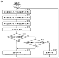
- FIG. 6 is a flowchart showing a control for switching between a normal mode and an oil recovery mode at startup.
- the control device 80 switches the operation mode of the refrigeration cycle device 100 between the normal mode and the oil recovery mode by executing the control according to FIG. 6 when the refrigeration cycle device 100 is started.
- the control device 80 acquires the discharge temperature Td of the compressor 1 from the first temperature sensor 51 (step S100). Next, the control device 80 acquires the condensation temperature CT of the first heat exchanger 2 from the second temperature sensor 52 (step S101). Next, the control device 80 acquires the evaporation temperature ET of the second heat exchanger 5 from the third temperature sensor 53 (step S102).
- the control device 80 calculates the discharge SH (Super Heat) (step S103).
- the discharge SH is calculated by calculating "discharge temperature Td-condensation temperature CT".
- the control device 80 determines whether or not the discharge SH is lower than the determination value (step S104).
- the determination value for determining the degree of discharge SH can be appropriately set, and for example, the determination value may be set to 10 ° C. It can be estimated that the larger the discharge SH is, the higher the degree of overheating of the refrigerant is, and the temperature of the refrigerant is equal to or higher than the separation temperature of the refrigerating machine oil. On the contrary, for example, when the discharge SH is lower than the determination value, it can be estimated that the temperature of the refrigerant is lower than the separation temperature of the refrigerating machine oil.
- step S106 when it is determined in step S104 that the discharge SH is lower than the determination value, the control device 80 operates in the oil recovery mode (step S106).
- the control device 80 controls the first decompression device 4 and the second decompression device 7 with an opening degree determined according to the oil recovery mode.
- the refrigerating machine oil separated from the refrigerant by the oil separator 3 is efficiently recovered in the compressor 1.
- the flow of control of the oil recovery mode will be described later with reference to FIG.
- step S104 when the control device 80 determines that the discharge SH is equal to or higher than the determination value, the control device 80 determines whether or not the evaporation temperature ET is equal to or lower than the oil separation temperature (step S105).
- the oil separation temperature used for the determination as described with reference to FIG. 3, it is preferable to determine a reference saturated dissolution rate in advance and adopt a value corresponding to the saturated dissolution rate.
- the control device 80 determines in step S105 that the evaporation temperature ET is equal to or lower than the oil separation temperature
- the control device 80 operates in the oil recovery mode (step S106).
- step S107 when it is determined in step S104 that the evaporation temperature ET exceeds the oil separation temperature, the control device 80 operates in the normal mode (step S107). The flow of control in the normal mode will be described later with reference to FIG.
- step S104 it may be determined whether or not the discharge temperature Td of the compressor 1 is lower than the determination value, instead of determining whether or not the discharge SH is lower than the determination value.
- the magnitude of the determination value to be compared with the discharge temperature Td is made different from the magnitude of the determination value to be compared with the ejection SH.
- the flowchart shown in FIG. 6 discloses a control for operating in the oil recovery mode when the discharge SH is lower than the determination value or the evaporation temperature ET is equal to or lower than the oil separation temperature at the time of starting.
- the oil recovery mode may be operated, and if the discharge SH is the determination value or more, the operation may be performed in the normal mode.
- the operation may be performed in the oil recovery mode, and when the evaporation temperature ET exceeds the oil separation temperature, the operation may be performed in the normal mode.
- FIG. 7 is a flowchart showing a control for switching between the normal mode and the oil recovery mode during operation.
- the control device 80 sets the operation mode of the refrigerating cycle device 100 into a normal mode and an oil recovery mode by executing the control based on FIG. 7 while the refrigerating cycle device 100 has finished starting and continues to operate. Switch between.
- the control device 80 acquires the evaporation temperature ET of the second heat exchanger 5 from the third temperature sensor 53 (step S200).
- the control device 80 determines whether or not the evaporation temperature ET is equal to or lower than the oil separation temperature (step S201).
- the oil separation temperature used for the determination as described with reference to FIG. 3, it is preferable to determine a reference saturated dissolution rate in advance and adopt a value corresponding to the saturated dissolution rate.
- the control device 80 determines in step S201 that the evaporation temperature ET is equal to or lower than the oil separation temperature
- the control device 80 operates in the oil recovery mode (step S202). Details of the control of the oil recovery mode will be described later with reference to FIG.
- the control device 80 operates in the normal mode (step S203). Details of the control in the normal mode will be described later with reference to FIG.
- FIG. 8 is a flowchart showing the control of the normal mode.
- the control device 80 controls the first decompression device 4 and the second decompression device 7 as follows. First, the control device 80 adjusts the opening degree of the pressure reducing valve of the first pressure reducing device 4 so that the discharge temperature and pressure correspond to the target capacity of the refrigerating cycle device 100 (step S300).
- the control device 80 reduces the opening degree of the pressure reducing valve of the second pressure reducing device 7 to the first opening degree (step S301).
- the first opening degree is an opening degree required to reduce the inflow amount of the refrigerant flowing from the oil separator 3 into the oil return pipe 61 per unit time.
- the first opening degree is 0%.
- the control device 80 realizes the normal mode by controlling the first decompression device 4 and the second decompression device 7 as in steps S300 and S301.
- the control device 80 may execute step S301 before step S300.
- FIG. 9 is a flowchart showing the control of the oil recovery mode.
- the control device 80 controls the first decompression device 4 and the second decompression device 7 as follows.
- the control device 80 reduces the opening degree of the pressure reducing valve of the first pressure reducing device 4 to the third opening degree (step S400).
- the third opening degree is smaller than the opening degree of the first decompression device 4 in the normal mode.
- control device 80 raises the opening degree of the pressure reducing valve of the second pressure reducing device 7 to a second opening degree larger than the first opening degree (step S401). This promotes the inflow of refrigerating machine oil from the oil separator 3 toward the oil return pipe 61.
- the second opening degree is 100%.
- the control device 80 realizes the oil recovery mode by controlling the first decompression device 4 and the second decompression device 7 as in steps S400 and S401.
- the control device 80 may execute step S401 before step S400.
- the refrigerating cycle apparatus 100 is operated in the normal mode when it is considered that the refrigerating machine oil is not separated from the refrigerant, and the refrigerating machine oil is separated from the refrigerant. If it is considered to be in a state, operate in oil recovery mode.
- the control device 80 may realize the oil recovery mode only in step S401 without executing step 400. That is, by controlling the second decompression device 7 as in step S401, the refrigerating machine oil can flow from the oil separator 3 toward the oil return pipe 61, and the oil recovery mode can be realized.
- the refrigerating cycle device 100 controls the oil return pipe 61 to be closed or almost closed by adjusting the degree of depressurization of the first decompression device 4 and the second decompression device 7.
- the refrigerating cycle device 100 adjusts the degree of depressurization of the first decompression device 4 and the second decompression device 7 so that the oil return path is substantially set. Adjustable to closed or almost closed normal mode. As a result, in the normal mode, it is possible to adjust so that the refrigerant does not flow from the oil separator 3 to the compressor 1 via the oil return pipe 61. As a result, a sufficient amount of refrigerant can be sent to the second heat exchanger 5.
- the refrigeration cycle device 100 can be adjusted to a state in which the oil return path from the oil return pipe 61 to the compressor 1 is open.
- the refrigeration cycle device 100 compresses from the oil return pipe 61 by adjusting the degree of decompression of the first decompression device 4 and the second decompression device 7 when the refrigerant and the refrigerating machine oil are separated by the oil separator 3. Open the return oil route to the machine 1.
- Embodiment 2 In the second embodiment, the refrigeration cycle apparatus 200 equipped with the third heat exchanger 8 will be described.
- FIG. 10 is a diagram showing the configuration of the refrigeration cycle apparatus 200 according to the second embodiment.
- FIG. 10 shows the flow of the refrigerant and the refrigerating machine oil when the refrigerating cycle device 200 is operating in the oil recovery mode.
- the refrigeration cycle device 200 includes a refrigerant circuit 20 and a control device 80.
- the refrigerant circuit 20 includes a third heat exchanger 8 in addition to the configuration of the refrigerant circuit 10.
- the third heat exchanger 8 includes a refrigerant pipe 60 flowing between the outlet b of the first heat exchanger 2 and the oil separator 3, an outlet g of the second decompression device 7, and a position h in front of the compressor 1.
- the third heat exchanger 8 is the refrigerant of the refrigerant pipe 60 flowing between the first heat exchanger 2 and the oil separator 3 and the refrigerant of the refrigerant pipe 60 flowing between the second decompression device 7 and the compressor 1. Exchange heat with. Therefore, the third heat exchanger 8 is an internal heat exchanger that exchanges heat between the refrigerants flowing in the refrigerant circuit 20.
- the opening degree of the pressure reducing valve of the first decompression device 4 is lower than that in the normal mode, and the decompression of the second decompression device 7 is performed, as in the refrigeration cycle device 100 according to the first embodiment.
- the valve opening is higher than in normal mode.
- the degree of decompression of the first decompression device 4 is higher than that of the normal mode, and the degree of decompression of the second decompression device 7 is lower than that of the normal mode.
- the operation of the third heat exchanger 8 will be described with reference to FIG.
- FIG. 11 is a ph diagram showing a change in the state of the refrigerant of the refrigerating cycle apparatus according to the second embodiment.
- Reference numerals a to h indicate the states of the refrigerant at the positions of the reference numerals a to h shown in the refrigerant circuit 20 of FIG.
- the third heat exchanger 8 is provided at the position shown in FIG. Therefore, in the section between the outlet b of the first heat exchanger 2 and the inlet e of the oil separator 3, and the section between the outlet g of the second decompression device 7 and the outlet h of the third heat exchanger 8. Heat exchange of the refrigerant is performed. Therefore, in the oil return pipe 61, the state of the refrigerant changes as e ⁇ g ⁇ h shown in FIG.
- the state of the refrigerant changes as e ⁇ c ⁇ f shown in FIG.
- the refrigerant that has flowed into the second heat exchanger 5 merges with the refrigerant that has flowed through the third heat exchanger 8 at position d, and then returns to the compressor 1.
- the broken line that crosses b and e and the broken line that crosses g and h indicate that heat exchange is performed between the sections b to e and the sections g to h.
- the refrigerant flowing out from the outlet b of the first heat exchanger 2 is cooled by the third heat exchanger 8 before flowing into the inlet e of the oil separator 3. Therefore, the temperature of the refrigerant flowing from the first heat exchanger 2 into the oil separator 3 is further lowered, and the degree of separation of the refrigerating machine oil from the refrigerant is improved. According to the second embodiment, the degree of separation of the refrigerating machine oil in the oil separator 3 can be improved, so that the refrigerating machine oil can be recovered more efficiently by the compressor 1.
- the refrigerating cycle apparatus 200 according to the second embodiment can be operated in the normal mode by executing the same control as the refrigerating cycle apparatus 100 according to the first embodiment, and further, the operation mode can be set to the normal mode. It is possible to switch between the mode and the oil recovery mode.
- Embodiment 3 In the third embodiment, the refrigeration cycle device 300 equipped with the four-way valve 11 will be described with respect to the refrigeration cycle device 200 according to the second embodiment.
- FIG. 12 is a diagram showing the configuration of the refrigeration cycle apparatus 300 according to the third embodiment.
- the refrigeration cycle device 300 includes a refrigerant circuit 30 and a control device 80.
- the refrigerant circuit 30 includes a four-way valve 11 in addition to the configuration of the refrigerant circuit 20 according to the second embodiment.
- the four-way valve 11 is provided on the discharge side of the compressor 1.
- the refrigerant circuit 30 includes a fourth temperature sensor 54 in addition to the configuration of the refrigerant circuit 20.
- the four-way valve 11 replaces the connection destination of the discharge port of the compressor 1 with the connection destination of the suction port of the compressor 1. By switching the connection method of the four-way valve 11, the heat exchanger connected to the discharge side of the compressor 1 can be switched between the second heat exchanger 5 and the first heat exchanger 2.
- FIG. 12 shows an example in which the second heat exchanger 5 is connected to the discharge side of the compressor 1. Since the second heat exchanger 5 is connected to the discharge side of the compressor 1, the refrigerant flows in the direction toward the first decompression device 4 via the compressor 1 and the second heat exchanger 5. This constitutes a second circulation path for circulating the refrigerant in the order of the compressor 1, the second heat exchanger 5, the first decompression device 4, the oil separator 3, the first heat exchanger 2, and the compressor 1. Therefore, the first heat exchanger 2 functions as an evaporator, and the second heat exchanger 5 functions as a condenser.
- the refrigeration cycle apparatus 300 In the normal mode, the refrigeration cycle apparatus 300 according to the third embodiment has a compressor 1, a first heat exchanger 2, a second heat exchanger 5, and a second heat exchanger so as to have a discharge temperature and a target pressure corresponding to the target capacity. 1 Controls the decompression device 4, the second decompression device 7, and the like. However, as shown in FIG. 12, when the second heat exchanger 5 is connected to the discharge side of the compressor 1, the circulation direction of the refrigerant is opposite to that of the refrigeration cycle device 100 according to the first embodiment.
- the refrigerant discharged from the compressor 1 flows into the second heat exchanger 5 together with the refrigerating machine oil.
- the refrigerant condensed in the second heat exchanger 5 flows into the first decompression device 4, is depressurized, and then flows into the oil separator 3. Therefore, the gas-liquid two-phase refrigerant and the refrigerating machine oil flow from the first decompression device 4 into the oil separator 3.
- the oil separator 3 functions as a gas-liquid separator that separates the liquid refrigerant and the gaseous refrigerant.
- the function of the oil separator 3 as a gas-liquid separator will be described with reference to FIG.
- FIG. 13 is a diagram showing the structure of the oil separator 3 that functions as a gas-liquid separator.
- the gas-liquid two-phase refrigerant and the refrigerating machine oil flow from the first decompression device 4 into the main body 31 of the oil separator 3 via the second pipe 33.
- the gaseous refrigerant moves above the main body 31.
- the liquid refrigerant and refrigerating machine oil move below the main body 31. Therefore, the gaseous refrigerant and the liquid refrigerant are separated by the oil separator 3.
- the boundary surface 42 between the gaseous refrigerant and the liquid refrigerant is formed in the main body 31.
- the boundary surface 42 shown is conceptual, and in reality, a gaseous refrigerant and a liquid refrigerant are mixed at the boundary.
- the gaseous refrigerant that has moved above the main body 31 is guided from the third pipe 34 to the second decompression device 7 via the oil return pipe 61 shown in FIG. Therefore, the oil return pipe 61 functions as a gas injection circuit.
- the liquid refrigerant that has moved below the main body 31 is guided to the third heat exchanger 8 via the first pipe 32.
- the operation of the third heat exchanger 8 will be described again with reference to FIG.
- the gaseous refrigerant separated by the oil separator 3 is cooled by being depressurized by the second decompression device 7.
- the cooled refrigerant passes through the third heat exchanger 8 and then returns to the compressor 1.
- a fourth temperature sensor 54 is provided at the outlet portion of the third heat exchanger 8.
- the temperature of the refrigerant at the outlet portion of the third heat exchanger 8 is detected by the fourth temperature sensor 54.
- the detected refrigerant temperature is input to the control device 80.
- the liquid refrigerant separated by the oil separator 3 flows into the third heat exchanger 8 before flowing into the first heat exchanger 2. Therefore, in the third heat exchanger 8, the refrigerant directed from the oil separator 3 to the first heat exchanger 2 is cooled by the refrigerant directed from the second decompression device 7 to the compressor 1. As a result, when the refrigerant flowing from the oil separator 3 to the first heat exchanger 2 contains a slightly gaseous refrigerant, the refrigerant directed from the second decompression device 7 to the compressor 1 uses the gaseous refrigerant. Moisten.
- the control device 80 adjusts the opening degree of the pressure reducing valve of the second pressure reducing device 7 based on the temperature detected by the fourth temperature sensor 54, and controls the temperature of the refrigerant from the second pressure reducing device 7 to the compressor 1. .. As a result, the degree of cooling of the refrigerant from the oil separator 3 to the first heat exchanger 2 is adjusted. As a result, the state of the refrigerant flowing from the oil separator 3 to the first heat exchanger 2 can be controlled to an ideal state in the refrigeration cycle.
- FIG. 14 is a ph diagram showing a change in the state of the refrigerant of the refrigerating cycle apparatus according to the third embodiment.
- Reference numerals a to j indicate the states of the refrigerant at the positions of the reference numerals a to j shown in the refrigerant circuit 30 of FIG.
- the compressor 1 discharges a high-temperature and high-pressure refrigerant to its discharge side f.
- a part of the refrigerating machine oil is discharged from the compressor 1 together with the refrigerant.
- the refrigerant discharged from the compressor 1 to the discharge side f flows into the second heat exchanger 5 that functions as a condenser.
- the refrigerant transitions from f to c shown in FIG.
- the refrigerant is depressurized by flowing into the first decompression device 4.
- the refrigerant transitions to the state i shown in FIG. 14, and becomes a gas-liquid two-phase state.
- the gas-liquid two-phase refrigerant flows into the oil separator 3 functioning as a gas-liquid separator together with the refrigerating machine oil.
- the oil separator 3 the gas-state refrigerant is separated into the upper layer, and the liquid-state refrigerant is separated into the lower layer.
- the refrigerating machine oil that has flowed into the oil separator 3 is separated into the lower layer of the oil separator 3 together with the liquid-state refrigerant.
- the gas-state refrigerant separated in the upper layer of the oil separator 3 exits the oil separator 3 and flows into the second decompression device 7, and is depressurized.
- the gas-state refrigerant separated in the upper layer of the oil separator 3 transitions from the state j shown in FIG. 14 to the state g.
- the refrigerant that has transitioned to the state of g goes to the third heat exchanger 8.
- the liquid-state refrigerant separated into the lower layer of the oil separator 3 leaves the oil separator 3 and heads for the third heat exchanger 8.
- the refrigerant at this time is in the state of j shown in FIG.
- the state of the former refrigerant changes from g to h
- the state of the latter refrigerant changes from e to b.
- the refrigerant in the state of h goes to the compressor 1.
- the refrigerant in the state b goes to the first heat exchanger 2 that functions as an evaporator.
- the third heat exchanger 8 can improve the heat transfer performance of the first heat exchanger 2 by changing the state of the refrigerant toward the first heat exchanger 2 from e to b.
- the refrigerant discharged from the first heat exchanger 2 is in the state of a shown in FIG.
- the first heat exchanger 2 when the connection of the four-way valve 11 is switched so that the first heat exchanger 2 is connected to the discharge side of the compressor 1, the first heat exchanger 2 functions as a condenser.
- the second heat exchanger 5 functions as an evaporator. Since the flow of the refrigerant and the refrigerating machine oil in this case has already been described with reference to FIG. 10, the description will not be repeated here. Further, since the operation of the refrigerant circuit 30 including the third heat exchanger 8 is the same as the operation of the refrigerant circuit 20 described with reference to FIG. 10, the description thereof will not be repeated here.
- the refrigeration cycle device 300 causes the oil separator 3 to function as a liquid-liquid separator that separates the refrigerating machine oil and the liquid refrigerant, as in the second embodiment.
- Embodiment 4 the refrigeration cycle device 400 equipped with the third decompression device 12 will be described with respect to the refrigeration cycle device 300 according to the third embodiment.
- the function of the oil separator 3 is a liquid-liquid separator by exchanging the connection destination of the discharge port of the compressor 1 and the connection destination of the suction port of the compressor 1 with the four-way valve 11. And the gas-liquid separator.
- the oil separator 3 functions as a liquid-liquid separator regardless of the mode of switching the four-way valve 11.
- the fourth embodiment will be described in detail with reference to the drawings.
- FIG. 15 is a diagram showing the configuration of the refrigeration cycle apparatus 400 according to the fourth embodiment.
- the refrigeration cycle device 400 includes a refrigerant circuit 40 and a control device 80.
- the refrigerant circuit 40 includes a third decompression device 12 in addition to the configuration of the refrigerant circuit 30.
- the third decompression device 12 is provided in the middle of the refrigerant pipe 60 connecting the oil separator 3 and the first heat exchanger 2. More specifically, the third decompression device 12 is located between the oil separator 3 and the third heat exchanger 8.
- FIG. 15 shows an example in which the second heat exchanger 5 is connected to the discharge side of the compressor 1 by the four-way valve 11. Since the second heat exchanger 5 is connected to the discharge side of the compressor 1, the refrigerant flows in the direction toward the first decompression device 4 via the compressor 1 and the second heat exchanger 5. As a result, the first heat exchanger 2 functions as an evaporator, and the second heat exchanger 5 functions as a condenser.
- the third decompression device 12 is located on the downstream side of the oil separator 3 in the direction in which the refrigerant flows and on the upstream side of the first heat exchanger 2 that functions as an evaporator.
- the arrangement of the third decompression device 12 is the same as the arrangement of the first decompression device 4 of the refrigeration cycle device 100 (see FIG. 1) according to the first embodiment. That is, in the refrigerant circuit 10 shown in FIG. 1, the first decompression device 4 is located downstream of the oil separator 3 in the direction in which the refrigerant flows and upstream of the second heat exchanger 5 functioning as an evaporator. do.
- the second heat exchanger (condenser) 5 the oil separator 3, the third decompression device 12, and the first heat in the refrigerant circuit 40 are ignored.
- Refrigerant flows in the order of the exchanger (evaporator) 2, and in the refrigerant circuit 10, the first heat exchanger (condenser) 2, the oil separator 3, the first decompression device 4, and the second heat exchanger (evaporator) ) It will be more easily understood that the flow of the refrigerant corresponds to the order of 5.
- the refrigerant circuit 10 and the refrigerant circuit 40 are common in that the oil separator 3 and the suction side of the compressor 1 are connected via the second decompression device 7.
- the refrigerating cycle apparatus 400 shown in FIG. 15 recovers oil as in the refrigerating cycle apparatus 100 (see FIG. 2) according to the first embodiment when the refrigerant flows as shown in the figure.
- the mode is feasible.
- the pressure reducing effect of the first pressure reducing device 4 is adjusted to a negligible degree, and the opening degree of the pressure reducing valve of the second pressure reducing device 7 is adjusted.
- the oil recovery mode can be realized by adjusting the opening degree of the pressure reducing valve of the third pressure reducing device 12.
- the opening degree of the pressure reducing valve of the first pressure reducing device 4, the second pressure reducing device 7, and the third pressure reducing device 12 is adjusted by the control device 80 of the refrigerating cycle device 400.
- the opening degree of the pressure reducing valve of the third pressure reducing device 12 may be adjusted according to the opening degree of the pressure reducing valve of the first pressure reducing device 4 for realizing the oil recovery mode according to the first embodiment.
- the opening degree of the pressure reducing valve of the second pressure reducing device 7 may be adjusted according to the opening degree of the pressure reducing valve of the second pressure reducing device 7 for realizing the oil recovery mode according to the first embodiment.
- the opening degree of the pressure reducing valve of the first pressure reducing device 4 in the oil recovery mode may be set so that the degree of the depressurization can be ignored, and it is not always necessary to adjust the opening degree to the maximum opening degree. The flow of control of the oil recovery mode will be described later with reference to FIG.
- the refrigerating cycle device 400 shown in FIG. 15 can realize a normal mode as in the refrigerating cycle device 100 (see FIG. 1) according to the first embodiment when the refrigerant flows as shown in the drawing.
- the pressure reducing effect of the first pressure reducing device 4 is adjusted to a negligible degree, and the opening degree of the pressure reducing valve of the third pressure reducing device 12 is adjusted.
- the opening degree of the pressure reducing valve of the second pressure reducing device 7 can be adjusted to realize the normal mode.
- the opening degree of the pressure reducing valve of the first pressure reducing device 4, the second pressure reducing device 7, and the third pressure reducing device 12 is adjusted by the control device 80 of the refrigerating cycle device 400.
- the opening degree of the pressure reducing valve of the third pressure reducing device 12 may be adjusted according to the opening degree of the pressure reducing valve of the first pressure reducing device 4 for realizing the normal mode according to the first embodiment.
- the opening degree of the pressure reducing valve of the second pressure reducing device 7 may be adjusted according to the opening degree of the pressure reducing valve of the second pressure reducing device 7 for realizing the normal mode according to the first embodiment.
- the opening degree of the pressure reducing valve of the first pressure reducing device 4 in the normal mode may be set so that the degree of the depressurization can be ignored, and it is not always necessary to adjust the opening degree to the maximum opening degree. The flow of control in the normal mode will be described later with reference to FIG.
- the refrigerating cycle device 400 shown in FIG. 15 can switch the operation mode between the normal mode and the oil recovery mode as in the refrigerating cycle device 100 according to the first embodiment when the refrigerant flows as shown in the drawing.
- the control flow for the refrigerating cycle apparatus 400 to switch the operation mode between the normal mode and the oil recovery mode is based on the control flow shown in FIGS. 6 and 7.
- the temperature detected by the second temperature sensor 52 is the evaporation temperature ET of the first heat exchanger 2 functioning as an evaporator
- the temperature detected by the third temperature sensor 53 is the condenser.
- It is a condensation temperature CT of the second heat exchanger 5 that functions as. Therefore, when the refrigerating cycle apparatus 400 executes the control according to the flowchart of FIG. 6 or FIG. 7, the condensation temperature CT is acquired from the detection value of the third temperature sensor 53 in step S101, and the condensation temperature CT is acquired from the detection value of the third temperature sensor 53, and in steps S102 and S200. , The evaporation temperature ET is acquired from the detection value of the second temperature sensor 52.
- FIG. 16 is a flowchart showing the control of the normal mode.
- this flowchart relates to the control of the normal mode when the second heat exchanger 5 is connected to the discharge side of the compressor 1 as shown in FIG.
- the control device 80 When the refrigerating cycle device 400 in the state where the second heat exchanger 5 is connected to the discharge side of the compressor 1 is operated in the normal mode, the control device 80 has the first decompression device 4, the second decompression device 7, and the control device 80.
- the third decompression device 12 is controlled as follows. First, the control device 80 maximizes (100%) the opening degree of the pressure reducing valve of the first pressure reducing device 4 (step S500). As a result, the decompression effect of the first decompression device 4 becomes negligible.
- the control device 80 reduces the opening degree of the pressure reducing valve of the second pressure reducing device 7 to the first opening degree (step S501).
- the first opening degree is an opening degree required to reduce the amount of the refrigerant flowing into the oil return pipe 61 from the oil separator 3.
- the first opening degree is 0%.
- control device 80 adjusts the opening degree of the pressure reducing valve of the first pressure reducing device 4 so that the discharge temperature and pressure correspond to the target capacity of the refrigerating cycle device 400 (step S502).
- the control device 80 realizes the normal mode by controlling the first decompression device 4, the second decompression device 7, and the third decompression device 12 as in steps S500 to S502.
- the order in which the control device 80 executes steps S500 to S502 may be changed to any order.
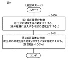
- FIG. 17 is a flowchart showing the control of the oil recovery mode.
- this flowchart relates to the control of the oil recovery mode when the second heat exchanger 5 is connected to the discharge side of the compressor 1 as shown in FIG.
- the control device 80 When the control device 80 operates the refrigeration cycle device 400 in a state where the second heat exchanger 5 is connected to the discharge side of the compressor 1 in the oil recovery mode, the first decompression device 4, the second decompression device 7, and the control device 80 And the third decompression device 12 is controlled as follows. First, the control device 80 maximizes (100%) the opening degree of the pressure reducing valve of the first pressure reducing device 4 (step S600). As a result, the decompression effect of the first decompression device 4 becomes negligible.
- control device 80 raises the opening degree of the pressure reducing valve of the second pressure reducing device 7 to a second opening degree larger than the first opening degree (step S601). This promotes the inflow of refrigerating machine oil from the oil separator 3 toward the oil return pipe 61.
- the second opening degree is 100%.
- the control device 80 reduces the opening degree of the pressure reducing valve of the third pressure reducing device 12 to the third opening degree (step S602).
- the third opening degree is smaller than the opening degree of the first decompression device 4 in the normal mode.
- the control device 80 realizes the oil recovery mode by controlling the first decompression device 4, the second decompression device 7, and the third decompression device 12 as in steps S600 to S602.
- the order in which the control device 80 executes steps S600 to S602 is not limited to the order shown in FIG. 17, and any step may be executed before the other steps.
- the control device 80 may realize the oil recovery mode without executing step 602. That is, by controlling the first decompression device 4 and the second decompression device 7 as in steps S600 and S601, the refrigerating machine oil can be flowed from the oil separator 3 toward the oil return pipe 61, and the oil recovery mode Can be realized.
- the refrigerating cycle device 400 has substantially the same configuration as the refrigerating cycle device 200 shown in FIG. 10, except that the refrigerating cycle device 400 includes the fourth temperature sensor 54. Therefore, in the refrigeration cycle device 400, when the first heat exchanger 2 is connected to the discharge side of the compressor 1, the control device 80 controls the opening degree of the pressure reducing valve of the third pressure reducing device 12 to the maximum. Similar to the refrigeration cycle device 200 shown in FIG. 10, the operation mode is set to the normal mode and the oil by adjusting the opening degree of the pressure reducing valve of the first pressure reducing device 4 and the opening degree of the pressure reducing valve of the second pressure reducing device 7. It is possible to switch to the recovery mode.
- the outside air temperature Tout may be acquired instead of the evaporation temperature ET or in addition to the evaporation temperature ET.
- the outside air temperature Tout means the temperature of the outside air in contact with the heat exchanger functioning as an evaporator.
- the temperature of the outside air in contact with the second heat exchanger 5 corresponds to the outside air temperature Tout.
- the temperature of the refrigerant is increased by comparing the outside air temperature Tout with the reference value in step S105 of FIG. 6 and step S201 of FIG. It may be determined whether or not it is below the oil separation temperature. Normally, the outside air temperature Tout is considered to be higher than the evaporation temperature ET. Therefore, when determining "outside air temperature Tout ⁇ reference value?" Instead of "evaporation temperature ET ⁇ oil separation temperature?", The "reference value” is a "constant value" with respect to the "oil separation temperature". It may be the added value.
- the "constant value” can be derived from the relationship between the outside air temperature and the evaporation temperature.
- the relationship between the outside air temperature and the evaporation temperature can be specified by operating a refrigeration cycle device provided with a sensor for detecting the condensation temperature and a sensor for detecting the outside air temperature, and acquiring the detection values of both sensors.
- step S104 of FIG. 6 it may be estimated whether or not the temperature of the refrigerant is lower than the separation temperature of the refrigerating machine oil by determining the discharge temperature Td as the reference value instead of the discharge SH.
- the condensation temperature CT may be calculated from the detection value of the pressure sensor provided on the discharge side of the compressor 1.
- the evaporation temperature ET may be calculated from the detected value of the pressure sensor provided on the suction side of the compressor 1.
- step S104 ⁇ Modification 5>
- step S104 ⁇ Modification 5>
- step S104 the process proceeds to step S107 to operate in the normal mode.
- step S107 the process immediately proceeds from step S103 to step S105.
- step S106 When it is determined to be YES in step S105, it is operated in the oil recovery mode (step S106), and when it is determined to be NO in step S105, it is operated in the normal mode (step S107).
- the refrigeration cycle device (100-400) includes a compressor (1), a first heat exchanger (2), a second heat exchanger (5), a first decompression device (4), and an oil separator ( 3), the first to circulate the refrigerant in the order of the compressor (1), the first heat exchanger (2), the oil separator (3), the first decompression device (4), and the second heat exchanger (5).
- An oil return path (61) connecting the circulation path, the oil separator (3) and the suction side of the compressor (1), a second decompression device (7) provided in the return path, and a first decompression device.
- a control device (80) for controlling the device (4) and the second decompression device (7) is provided, and the control device (80) uses an oil separator (3) for the refrigerant flowing in the first circulation path and the refrigerating machine oil.
- the operation mode is changed to the oil recovery mode (S106 in FIG. 6 and S202 in FIG. 7) in which the oil return path (61) is opened. ) Is configured.
- control device (80) adjusts the degree of decompression of the second decompression device (7) when the refrigerant flowing in the first circulation path and the refrigerating machine oil are not separated by the oil separator (3).
- the operation mode is configured to be set to the normal mode (S107 in FIG. 6 and S203 in FIG. 7) in which the oil return path is closed.
- control device suppresses the inflow of the refrigerant from the oil separator to the first decompression device and separates the oil in the oil recovery mode (S106 in FIG. 6 and S202 in FIG. 7) as compared with the normal mode.
- the degree of decompression of the first decompression device is adjusted so that the temperature of the refrigerant flowing into the vessel is lowered.
- control device adjusts the degree of depressurization of the first decompression device (4) and the second decompression device (7) so as to block the oil return path (61) in the first circulation path. It is configured so that it can be circulated.
- a first temperature sensor (51) for detecting the temperature of the refrigerant flowing on the discharge side of the compressor (1) is further provided, and the control device (80) is when the refrigeration cycle device (100 to 400) is started. Using the temperature detected by the first temperature sensor (51), it is determined whether or not the operation mode is set to the oil recovery mode (S106 in FIG. 6, S202 in FIG. 7).
- a second temperature sensor (52) for detecting the temperature of the refrigerant flowing through the first heat exchanger (2) is further provided, and the control device includes the temperature detected by the first temperature sensor (51) and the second temperature sensor. Based on the degree of superheat calculated from the temperature detected by (52), it is determined whether or not the operation mode is set to the oil recovery mode (S106 in FIG. 6) (S104 in FIG. 6).
- control device (80) further comprises a third temperature sensor (53) that detects the temperature of the refrigerant flowing through the second heat exchanger (5) or the temperature of the outside air in contact with the second heat exchanger (5). , It is determined whether or not the operation mode is set to the oil recovery mode (S202 in FIG. 7) by using the temperature detected by the third temperature sensor (53) during the operation of the refrigeration cycle device (100 to 400). (S201 in FIG. 7).
- heat is generated between the refrigerant flowing between the first heat exchanger (2) and the oil separator (3) and the refrigerant flowing between the second decompressing device (7) and the compressor (1).
- a third heat exchanger (8) is further provided.
- the four-way valve (11) is further provided, and the four-way valve (11) switches the direction in which the refrigerant circulates between the first circulation path and the second circulation path, and in the second circulation path, the compressor (1),.
- the refrigerant circulates in the order of the second heat exchanger (5), the first decompressor (4), the oil separator (3), and the first heat exchanger (2), and the oil separator (3) circulates in the second circulation.
- the gaseous refrigerant is returned to the compressor (1) via the oil return path (61).
- a four-way valve (11) is further provided with a third decompression device (12) provided in the path of the refrigerant flowing between the oil separator (3) and the first heat exchanger (2), and the four-way valve is further provided.
- the direction in which the refrigerant circulates is switched between the first circulation path and the second circulation path, and in the second circulation path, the compressor (1), the second heat exchanger (5), and the first decompression device (1). 4), the oil separator (3), and the first heat exchanger (2) circulate in this order, and in the control device (80), the refrigerant flowing in the second circulation path and the refrigerating machine oil are in the oil separator (3).
- the operation mode is set to the oil recovery mode by adjusting the degree of decompression of the first decompression device (4) and the second decompression device (7) at the time of separation.
- control device (80) adjusts the degree of decompression of the first decompression device (1) to suppress the inflow of the refrigerant from the oil separator (3) to the first decompression device (4).
- the oil recovery mode (S106 in FIG. 6) Set to S202) in FIG. 7.
- control device (80) is an oil separator (3) that separates the refrigerant and the refrigerating machine oil by adjusting the degree of decompression of the first decompression device (1) and the second decompression device (7). ),
- the operation mode is set to the oil recovery mode in which the oil return path is open.
- 1 Compressor 2 1st heat exchanger, 3 oil separator, 4 1st decompression device, 5 2nd heat exchanger, 7 2nd decompression device, 8 3rd heat exchanger, 10, 20, 30 refrigerant circuit, 11 four-way valve, 12 third decompression device, 31 main body, 32 first pipe, 33 second pipe, 34 third pipe, 41 boundary surface, 42 boundary surface, 51 first temperature sensor, 52 second temperature sensor, 53 3rd temperature sensor, 54 4th temperature sensor, 60 refrigerant pipe, 61 oil return pipe, 80 control device, 81 control board, 82 processor, 83 memory, 100, 200, 300 refrigeration cycle device.
Landscapes
- Engineering & Computer Science (AREA)
- Physics & Mathematics (AREA)
- Mechanical Engineering (AREA)
- Thermal Sciences (AREA)
- General Engineering & Computer Science (AREA)
- Chemical & Material Sciences (AREA)
- Analytical Chemistry (AREA)
- Power Engineering (AREA)
- Compression-Type Refrigeration Machines With Reversible Cycles (AREA)
- Air Conditioning Control Device (AREA)
Abstract
L'appareil à cycle de réfrigération (100) selon l'invention comprend : un compresseur (1) ; un premier échangeur de chaleur (2) ; un second échangeur de chaleur (5) ; un premier dispositif de dépressurisation (4) ; un séparateur d'huile (3) ; un premier trajet de circulation qui fait circuler un réfrigérant à travers le compresseur (1), le premier échangeur de chaleur (2), le séparateur d'huile (3), le premier dispositif de dépressurisation (4) et le second échangeur de chaleur (5) dans l'ordre indiqué ; un trajet de retour d'huile qui relie le séparateur d'huile (3) et le côté admission du compresseur (1) ; un second dispositif de dépressurisation (7) placé sur le trajet de retour d'huile ; et un dispositif de commande (80) qui commande le premier dispositif de dépressurisation (4) et le second dispositif de dépressurisation (7). Le dispositif de commande (80) est conçu de telle sorte que, lorsque le réfrigérant s'écoulant à travers le premier trajet de circulation et une huile de réfrigération sont séparés par le séparateur d'huile (3), le dispositif de commande (80) ajuste la valeur de dépressurisation par le premier dispositif de dépressurisation (4) et le second dispositif de dépressurisation (7), un mode de fonctionnement étant réglé sur un mode de récupération d'huile (S106 sur la FIG. 6, S202 sur la FIG. 7) dans lequel le trajet de retour d'huile (61) est ouvert.
Priority Applications (4)
| Application Number | Priority Date | Filing Date | Title |
|---|---|---|---|
| PCT/JP2020/041211 WO2022097201A1 (fr) | 2020-11-04 | 2020-11-04 | Appareil à cycle de réfrigération |
| EP20960755.5A EP4242551A4 (fr) | 2020-11-04 | 2020-11-04 | Appareil à cycle de réfrigération |
| JP2022560541A JPWO2022097201A1 (fr) | 2020-11-04 | 2020-11-04 | |
| US18/027,980 US20230375236A1 (en) | 2020-11-04 | 2020-11-04 | Refrigeration Cycle Apparatus |
Applications Claiming Priority (1)
| Application Number | Priority Date | Filing Date | Title |
|---|---|---|---|
| PCT/JP2020/041211 WO2022097201A1 (fr) | 2020-11-04 | 2020-11-04 | Appareil à cycle de réfrigération |
Publications (1)
| Publication Number | Publication Date |
|---|---|
| WO2022097201A1 true WO2022097201A1 (fr) | 2022-05-12 |
Family
ID=81457630
Family Applications (1)
| Application Number | Title | Priority Date | Filing Date |
|---|---|---|---|
| PCT/JP2020/041211 WO2022097201A1 (fr) | 2020-11-04 | 2020-11-04 | Appareil à cycle de réfrigération |
Country Status (4)
| Country | Link |
|---|---|
| US (1) | US20230375236A1 (fr) |
| EP (1) | EP4242551A4 (fr) |
| JP (1) | JPWO2022097201A1 (fr) |
| WO (1) | WO2022097201A1 (fr) |
Citations (4)
| Publication number | Priority date | Publication date | Assignee | Title |
|---|---|---|---|---|
| JPS63159156U (fr) * | 1987-04-07 | 1988-10-18 | ||
| JPH0674579A (ja) * | 1992-08-26 | 1994-03-15 | Daikin Ind Ltd | 冷凍装置 |
| JPH0886519A (ja) | 1994-09-20 | 1996-04-02 | Mitsubishi Electric Corp | 冷凍空調装置 |
| JP2005083704A (ja) * | 2003-09-10 | 2005-03-31 | Mitsubishi Electric Corp | 冷凍サイクル、空気調和機 |
Family Cites Families (2)
| Publication number | Priority date | Publication date | Assignee | Title |
|---|---|---|---|---|
| JP2002303456A (ja) * | 1997-08-19 | 2002-10-18 | Mitsubishi Electric Corp | 冷凍空調装置 |
| JP4787070B2 (ja) * | 2006-05-30 | 2011-10-05 | サンデン株式会社 | 冷凍サイクル |
-
2020
- 2020-11-04 WO PCT/JP2020/041211 patent/WO2022097201A1/fr unknown
- 2020-11-04 EP EP20960755.5A patent/EP4242551A4/fr not_active Withdrawn
- 2020-11-04 US US18/027,980 patent/US20230375236A1/en active Pending
- 2020-11-04 JP JP2022560541A patent/JPWO2022097201A1/ja not_active Ceased
Patent Citations (4)
| Publication number | Priority date | Publication date | Assignee | Title |
|---|---|---|---|---|
| JPS63159156U (fr) * | 1987-04-07 | 1988-10-18 | ||
| JPH0674579A (ja) * | 1992-08-26 | 1994-03-15 | Daikin Ind Ltd | 冷凍装置 |
| JPH0886519A (ja) | 1994-09-20 | 1996-04-02 | Mitsubishi Electric Corp | 冷凍空調装置 |
| JP2005083704A (ja) * | 2003-09-10 | 2005-03-31 | Mitsubishi Electric Corp | 冷凍サイクル、空気調和機 |
Non-Patent Citations (1)
| Title |
|---|
| See also references of EP4242551A4 |
Also Published As
| Publication number | Publication date |
|---|---|
| EP4242551A1 (fr) | 2023-09-13 |
| JPWO2022097201A1 (fr) | 2022-05-12 |
| US20230375236A1 (en) | 2023-11-23 |
| EP4242551A4 (fr) | 2023-12-06 |
Similar Documents
| Publication | Publication Date | Title |
|---|---|---|
| JP5452138B2 (ja) | 冷凍空調装置 | |
| JP4931848B2 (ja) | ヒートポンプ式給湯用室外機 | |
| JP4725387B2 (ja) | 空気調和装置 | |
| KR100856991B1 (ko) | 냉동 공조장치, 냉동 공조장치의 운전 제어 방법, 냉동공조장치의 냉매량 제어 방법 | |
| JP4375171B2 (ja) | 冷凍装置 | |
| JP4776438B2 (ja) | 冷凍サイクル | |
| WO2007110908A9 (fr) | Dispositif de climatisation frigorifique | |
| JP2006078087A (ja) | 冷凍装置 | |
| JP5332093B2 (ja) | 冷凍装置 | |
| JP4752765B2 (ja) | 空気調和装置 | |
| JP2007187407A (ja) | 冷凍サイクル装置及び冷凍サイクル装置の運転方法 | |
| JP4550153B2 (ja) | ヒートポンプ装置及びヒートポンプ装置の室外機 | |
| JP2009030954A (ja) | 冷凍装置 | |
| JP4442237B2 (ja) | 空気調和装置 | |
| JP2007155229A (ja) | 蒸気圧縮式冷凍サイクル | |
| JP6341326B2 (ja) | 冷凍装置の熱源ユニット | |
| JP4767340B2 (ja) | ヒートポンプ装置の制御装置 | |
| JP2007093100A (ja) | ヒートポンプ給湯機の制御方法及びヒートポンプ給湯機 | |
| JP2008008499A (ja) | 冷凍サイクル装置及びヒートポンプ式給湯機 | |
| JP5659909B2 (ja) | ヒートポンプ装置 | |
| JP2009243881A (ja) | ヒートポンプ装置及びヒートポンプ装置の室外機 | |
| CN111919073B (zh) | 制冷装置 | |
| JP2008190757A (ja) | 冷凍装置 | |
| WO2022097201A1 (fr) | Appareil à cycle de réfrigération | |
| JP7378561B2 (ja) | 室外ユニットおよび冷凍サイクル装置 |
Legal Events
| Date | Code | Title | Description |
|---|---|---|---|
| 121 | Ep: the epo has been informed by wipo that ep was designated in this application |
Ref document number: 20960755 Country of ref document: EP Kind code of ref document: A1 |
|
| ENP | Entry into the national phase |
Ref document number: 2022560541 Country of ref document: JP Kind code of ref document: A |
|
| NENP | Non-entry into the national phase |
Ref country code: DE |
|
| ENP | Entry into the national phase |
Ref document number: 2020960755 Country of ref document: EP Effective date: 20230605 |