WO2022085698A1 - 接着剤組成物及びこれを用いた貼合体の製造方法 - Google Patents
接着剤組成物及びこれを用いた貼合体の製造方法 Download PDFInfo
- Publication number
- WO2022085698A1 WO2022085698A1 PCT/JP2021/038664 JP2021038664W WO2022085698A1 WO 2022085698 A1 WO2022085698 A1 WO 2022085698A1 JP 2021038664 W JP2021038664 W JP 2021038664W WO 2022085698 A1 WO2022085698 A1 WO 2022085698A1
- Authority
- WO
- WIPO (PCT)
- Prior art keywords
- meth
- adhesive composition
- acrylate
- adhesive
- mass
- Prior art date
- Legal status (The legal status is an assumption and is not a legal conclusion. Google has not performed a legal analysis and makes no representation as to the accuracy of the status listed.)
- Ceased
Links
Images


Classifications
-
- C—CHEMISTRY; METALLURGY
- C08—ORGANIC MACROMOLECULAR COMPOUNDS; THEIR PREPARATION OR CHEMICAL WORKING-UP; COMPOSITIONS BASED THEREON
- C08G—MACROMOLECULAR COMPOUNDS OBTAINED OTHERWISE THAN BY REACTIONS ONLY INVOLVING UNSATURATED CARBON-TO-CARBON BONDS
- C08G59/00—Polycondensates containing more than one epoxy group per molecule; Macromolecules obtained by polymerising compounds containing more than one epoxy group per molecule using curing agents or catalysts which react with the epoxy groups
- C08G59/18—Macromolecules obtained by polymerising compounds containing more than one epoxy group per molecule using curing agents or catalysts which react with the epoxy groups ; e.g. general methods of curing
- C08G59/68—Macromolecules obtained by polymerising compounds containing more than one epoxy group per molecule using curing agents or catalysts which react with the epoxy groups ; e.g. general methods of curing characterised by the catalysts used
-
- C—CHEMISTRY; METALLURGY
- C09—DYES; PAINTS; POLISHES; NATURAL RESINS; ADHESIVES; COMPOSITIONS NOT OTHERWISE PROVIDED FOR; APPLICATIONS OF MATERIALS NOT OTHERWISE PROVIDED FOR
- C09J—ADHESIVES; NON-MECHANICAL ASPECTS OF ADHESIVE PROCESSES IN GENERAL; ADHESIVE PROCESSES NOT PROVIDED FOR ELSEWHERE; USE OF MATERIALS AS ADHESIVES
- C09J11/00—Features of adhesives not provided for in group C09J9/00, e.g. additives
- C09J11/02—Non-macromolecular additives
- C09J11/06—Non-macromolecular additives organic
-
- C—CHEMISTRY; METALLURGY
- C09—DYES; PAINTS; POLISHES; NATURAL RESINS; ADHESIVES; COMPOSITIONS NOT OTHERWISE PROVIDED FOR; APPLICATIONS OF MATERIALS NOT OTHERWISE PROVIDED FOR
- C09J—ADHESIVES; NON-MECHANICAL ASPECTS OF ADHESIVE PROCESSES IN GENERAL; ADHESIVE PROCESSES NOT PROVIDED FOR ELSEWHERE; USE OF MATERIALS AS ADHESIVES
- C09J163/00—Adhesives based on epoxy resins; Adhesives based on derivatives of epoxy resins
-
- C—CHEMISTRY; METALLURGY
- C09—DYES; PAINTS; POLISHES; NATURAL RESINS; ADHESIVES; COMPOSITIONS NOT OTHERWISE PROVIDED FOR; APPLICATIONS OF MATERIALS NOT OTHERWISE PROVIDED FOR
- C09J—ADHESIVES; NON-MECHANICAL ASPECTS OF ADHESIVE PROCESSES IN GENERAL; ADHESIVE PROCESSES NOT PROVIDED FOR ELSEWHERE; USE OF MATERIALS AS ADHESIVES
- C09J4/00—Adhesives based on organic non-macromolecular compounds having at least one polymerisable carbon-to-carbon unsaturated bond ; adhesives, based on monomers of macromolecular compounds of groups C09J183/00 - C09J183/16
-
- C—CHEMISTRY; METALLURGY
- C09—DYES; PAINTS; POLISHES; NATURAL RESINS; ADHESIVES; COMPOSITIONS NOT OTHERWISE PROVIDED FOR; APPLICATIONS OF MATERIALS NOT OTHERWISE PROVIDED FOR
- C09J—ADHESIVES; NON-MECHANICAL ASPECTS OF ADHESIVE PROCESSES IN GENERAL; ADHESIVE PROCESSES NOT PROVIDED FOR ELSEWHERE; USE OF MATERIALS AS ADHESIVES
- C09J4/00—Adhesives based on organic non-macromolecular compounds having at least one polymerisable carbon-to-carbon unsaturated bond ; adhesives, based on monomers of macromolecular compounds of groups C09J183/00 - C09J183/16
- C09J4/06—Organic non-macromolecular compounds having at least one polymerisable carbon-to-carbon unsaturated bond in combination with a macromolecular compound other than an unsaturated polymer of groups C09J159/00 - C09J187/00
-
- C—CHEMISTRY; METALLURGY
- C09—DYES; PAINTS; POLISHES; NATURAL RESINS; ADHESIVES; COMPOSITIONS NOT OTHERWISE PROVIDED FOR; APPLICATIONS OF MATERIALS NOT OTHERWISE PROVIDED FOR
- C09J—ADHESIVES; NON-MECHANICAL ASPECTS OF ADHESIVE PROCESSES IN GENERAL; ADHESIVE PROCESSES NOT PROVIDED FOR ELSEWHERE; USE OF MATERIALS AS ADHESIVES
- C09J5/00—Adhesive processes in general; Adhesive processes not provided for elsewhere, e.g. relating to primers
Definitions
- This technique relates to an adhesive composition and a method for producing a bonded body using the adhesive composition.
- This application claims priority on the basis of Japanese Patent Application No. 2020-175782 filed on October 20, 2020 in Japan, and this application is referred to in this application. It will be used.
- the adherends such as the image display device and the front cover, the image display device and the touch panel, and the front cover and the touch panel are bonded together with an optical transparent adhesive such as OCR (Optical Clear Resin) or LOCA (Liquid Optically Clear Adhesive), respectively.
- OCR Optical Clear Resin
- LOCA Liquid Optically Clear Adhesive
- -Fixing techniques are known (for example, Patent Documents 1 to 3).
- a UV delayed curing type adhesive has also been proposed as a method for curing a UV (Ultraviolet) opaque portion.
- Patent Documents 1 and 2 describe a resin composition containing a polyfunctional epoxy resin, a monofunctional epoxy resin, and a polyfunctional oxetane resin as a UV delayed curing type adhesive.
- Patent Document 3 contains a radically polymerizable group-containing compound, a cationically polymerizable group-containing compound, a photoradical initiator, and a photoacid generator, and the content of the radically polymerizable group-containing compound is cationically polymerizable.
- the photoradical initiator is at least one of an ⁇ -hydroxyalkylphenone-based photoradical initiator and a benzylmethyl ketal-based photoradical initiator, and the photoradical initiator and the photoacid generator.
- a photocurable resin composition having a mass ratio (photoradical initiator / photoacid generator) of 0.5 to 30 is described.
- the UV curable resin compositions described in Patent Documents 1 and 2 are epoxy-cationic curable systems, the start of curing is slower than that of acrylic-radical curable systems.
- the monofunctional epoxy monomer has a slow start of curing. Therefore, when the epoxy-cationic curing adhesive described in Patent Documents 1 and 2 is used as an adhesive for inkjet coating having a low viscosity, curing does not start immediately after UV irradiation, so that the coating shape is maintained. Is concerned that it will be difficult.
- the conventional acrylic-radical curable UV curable resin composition does not easily lose its coating shape after UV irradiation, but if the elastic modulus after curing is high, it tends to be difficult to bond the adherends to each other due to repulsion. be. Therefore, in the conventional acrylic-radical curable UV curable resin composition, it is necessary that the elastic modulus after curing is low, and it is difficult to obtain sufficient adhesive strength.
- This technique has been proposed in view of such conventional circumstances, and is an adhesive composition that can maintain the coating shape after UV irradiation and has good adhesive strength after curing, and a bonded product using the same. Provides a manufacturing method for.
- the adhesive composition according to the present technology is at least selected from the group consisting of 45 to 70% by mass of epoxy resin and aromatic (meth) acrylate, alicyclic (meth) acrylate and heterocyclic (meth) acrylate. It contains one kind of first (meth) acrylate component, a second (meth) acrylate component composed of a hydroxyl group-containing (meth) acrylate, a radical photopolymerization initiator, and a cationic photopolymerization initiator.
- the adhesive composition according to the present technology comprises a hydrogenated epoxy resin of more than 30% by mass and 70% by mass or less, and an aromatic (meth) acrylate, an alicyclic (meth) acrylate and a heterocyclic (meth) acrylate.
- the method for producing a bonded body according to the present technology includes a step A of applying the above-mentioned adhesive composition to a first adherend to form an adhesive composition layer and irradiating the adhesive composition layer with ultraviolet rays.
- step B of forming the adhesive cured layer the second adherend is placed on the surface of the adhesive cured layer, and the first adherend and the second adherend are combined with the adhesive cured layer. It has a step C of joining through.
- This technique can maintain the coating shape after UV irradiation and can provide an adhesive composition having good adhesive strength after curing.
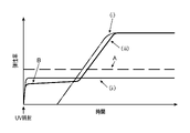
- FIG. 1 is a graph for explaining the change in elastic modulus with time of the adhesive composition.
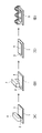
- 2A and 2B are perspective views for explaining an example of a method for manufacturing a bonded body using an adhesive composition
- FIG. 2A is a perspective view for explaining step A
- FIG. 2B is a perspective view for explaining step A.
- (C) and (D) are perspective views for demonstrating process C.
- 3A and 3B are perspective views for explaining another example of a method for producing a bonded body using an adhesive composition
- FIG. 3A is a perspective view for explaining step A
- FIG. 3B is a perspective view for explaining step A.
- (C) and (D) are perspective views for demonstrating process C.
- FIG. 4 is a perspective view for explaining a method of a high temperature holding force test.
- the adhesive composition according to the present technology is at least selected from the group consisting of 45 to 70% by mass of epoxy resin and aromatic (meth) acrylate, alicyclic (meth) acrylate and heterocyclic (meth) acrylate. It contains one kind of first (meth) acrylate component, a second (meth) acrylate component composed of a hydroxyl group-containing (meth) acrylate, a radical photopolymerization initiator, and a cationic photopolymerization initiator.
- FIG. 1 is a graph for explaining the change in elastic modulus with time of the adhesive composition.
- the horizontal axis represents time and the vertical axis represents elastic modulus.
- a in FIG. 1 represents an elastic modulus (based on Darkist) that can be bonded.
- the graph (i) in FIG. 1 shows the change in elastic modulus with time when, for example, the conventional epoxy-cationic curable UV curable resin composition described in Patent Documents 1 and 2 described above is used.
- the graph (ii) in FIG. 1 shows the change in elastic modulus with time when a conventional acrylic-radical curable UV curable resin composition is used.
- the graph (iii) in FIG. 1 shows the change in elastic modulus with time when the adhesive composition (combination of epoxy-cationic curing system and acrylic-radical curing system) according to the present technique is used.
- the adhesive composition according to the present technology starts curing immediately after UV irradiation, as shown in B in FIG. Therefore, the adhesive force and the shape-retaining force can be exhibited immediately after UV irradiation.
- the epoxy resin in the adhesive composition according to the present technology does not completely cure and contributes to lowering the elasticity of the adhesive composition as a plastic component.
- the adhesive composition according to the present technology has improved adhesiveness and adhesiveness after UV irradiation.
- the adhesive composition according to this technique exhibits delayed curability by containing an epoxy resin and a cationic photopolymerization initiator. Therefore, the adhesive composition according to the present technology can start delayed curing by being left at room temperature (and heated if necessary) after UV irradiation, and can exhibit high adhesive strength.
- the adhesive composition according to the present technology is more effective in adhesiveness (adhesive strength) and delayed curability by using the first (meth) acrylate component and the second (meth) acrylate component in combination. Can be expressed in.
- the adhesive composition according to the present technology can maintain the coating shape after UV irradiation and can improve the adhesive strength after curing.
- the epoxy resin may be a monofunctional epoxy compound having one epoxy group in one molecule, or a polyfunctional epoxy compound having two or more epoxy groups in one molecule.
- the epoxy resin is preferably a polyfunctional epoxy compound, and more preferably a bifunctional epoxy resin.
- the epoxy resin may be solid at room temperature or liquid at room temperature.
- the normal temperature refers to the range of 15 to 25 ° C. specified in JIS K0050: 2019 (general rule of chemical analysis method).
- the epoxy group contained in the epoxy resin may be an alicyclic epoxy group or a non-alicyclic epoxy group.
- the epoxy resin include bisphenol type epoxy compounds such as polybutadiene epoxy resin, bisphenol A type epoxy resin, and bisphenol F type epoxy resin, naphthalene type epoxy compounds, aliphatic epoxy compounds, biphenyl type epoxies, and glycidylamine type epoxy compounds.
- Alcohol type epoxy compounds such as hydrogenated bisphenol A type epoxy compounds, epoxy-modified silicones, phenol novolac type epoxy compounds, novolak type epoxy compounds such as cresol novolak type epoxy compounds, alicyclic epoxy compounds, polyfunctional epoxy compounds, glycidyl ethers.
- examples thereof include a polyester compound, an epoxy group-containing polyurethane compound, and an epoxy group-containing acrylic compound.
- the bisphenol F type epoxy resin is preferable from the viewpoint of maintaining the delayed curability of the adhesive composition after UV irradiation.
- a hydrogenated epoxy resin (hydrogenated epoxy resin) can also be used. Hydrogenated epoxy resin is preferable from the viewpoint of transmittance after curing and color resistance of the adhesive composition.
- the epoxy equivalent of the epoxy resin can be, for example, 150 to 300 g / eq, or 180 to 220.
- the viscosity of the epoxy resin at 25 ° C. is preferably 500 to 10,000 mPa ⁇ s.
- epoxy resin products examples include jERYX8000, YX8034 (all manufactured by Mitsubishi Chemical Corporation), EPICLON EXA-830CRP (manufactured by DIC Corporation), and the like.
- the epoxy resin may be used alone or in combination of two or more.
- the content of the epoxy resin in the adhesive composition is 45% by mass or more, may be 50% by mass or more, or may be 53% by mass or more. When the content of the epoxy resin in the adhesive composition is 45% by mass or more, high adhesive strength can be exhibited after UV irradiation.
- the upper limit of the content of the epoxy resin in the adhesive composition is 70% by mass or less, may be 65% by mass or less, or may be 60% by mass or less. Since the content of the epoxy resin in the adhesive composition is 70% by mass or less, other components (for example, the first (meth) acrylate component and the second (meth) acrylate component) are relatively small. It does not become too much and can develop adhesive strength and shape retention after UV irradiation.
- the content of the hydrogenated epoxy resin in the adhesive composition satisfies the above numerical range.
- the adhesive composition contains two or more kinds of epoxy resins, it is preferable that the total amount of the epoxy resins satisfies the above numerical range.
- the first (meth) acrylate component is selected from the group consisting of aromatic (meth) acrylates, alicyclic (meth) acrylates and heterocyclic (meth) acrylates.
- the first (meth) acrylate component may be used alone or in combination of two or more.
- the first (meth) acrylate component may be monofunctional or bifunctional or higher, but is preferably monofunctional.
- Aromatic (meth) acrylate is a (meth) acrylate having an aromatic hydrocarbon group.
- the number of carbon atoms of the aromatic hydrocarbon group in the aromatic (meth) acrylate can be 6 to 30, and may be 6 to 18.
- the aromatic hydrocarbon group may have a monocyclic structure or a polycyclic structure.
- the aromatic hydrocarbon group may have a substituent or may be unsubstituted.
- aromatic (meth) acrylates include benzyl (meth) acrylate, phenyl (meth) acrylate, phenoxyethyl (meth) acrylate, phenoxypolyethylene glycol (meth) acrylate, nonylphenoxypolyethylene glycol (meth) acrylate, and phenoxypolypropylene.
- examples thereof include glycol (meth) acrylate, 2- (meth) acryloyloxyethyl-2-hydroxypropylphthalate, and 2-hydroxy-3-phenoxypropyl (meth) acrylate.
- benzyl (meth) acrylate is preferable, and benzyl acrylate is more preferable, from the viewpoint of more effectively expressing the adhesive force and shape retention force of the adhesive composition after UV irradiation.
- An example of a product of aromatic (meth) acrylate is Viscoat 160 (manufactured by Osaka Organic Chemical Industry Co., Ltd.).
- the alicyclic (meth) acrylate is a (meth) acrylate having an alicyclic structure.
- the number of carbon atoms constituting the alicyclic structure in the alicyclic (meth) acrylate can be, for example, 4 to 30, may be 4 to 20, may be 4 to 10, and may be 4 to 8. May be.
- the alicyclic structure in the alicyclic (meth) acrylate may be a monocyclic structure or a polycyclic structure.
- the alicyclic structure in the alicyclic (meth) acrylate may be saturated or unsaturated.
- the alicyclic hydrocarbon group may have a substituent or may be unsubstituted.
- alicyclic (meth) acrylate examples include cyclohexyl (meth) acrylate, isobornyl (meth) acrylate, dicyclopentanyl (meth) acrylate, dicyclopentenyl (meth) acrylate, and dicyclopentenyloxy (meth) acrylate.
- cyclohexyl (meth) acrylate is preferable, and cyclohexyl acrylate is more preferable, from the viewpoint of more effectively expressing the adhesive force and shape retention force of the adhesive composition after UV irradiation.
- product examples of alicyclic (meth) acrylate include Viscoat 155 (manufactured by Osaka Organic Chemical Industry Co., Ltd.).
- the heterocyclic (meth) acrylate has, for example, at least one of a nitrogen atom, an oxygen atom, and a sulfur atom as a heteroatom of the heterocycle.
- the number of carbon atoms constituting the heterocycle can be 3 to 10, and can be 3 to 8.
- the heterocycle may have a monocyclic structure or a polycyclic structure.
- the heterocycle may have a substituent or may be unsubstituted.
- Specific examples of the heterocyclic (meth) acrylate include tetrahydrofurfuryl (meth) acrylate, 4-tetrahydropyranyl acrylate, 2-tetrahydropyranylmethyl acrylate and the like.
- tetrahydrofurfuryl (meth) acrylate is preferable, and tetrahydrofurfuryl acrylate is more preferable, from the viewpoint of more effectively expressing the adhesive force and shape retention force of the adhesive composition after UV irradiation.
- examples of products of the heterocyclic (meth) acrylate include Viscoat 150 (manufactured by Osaka Organic Chemical Industry Co., Ltd.).
- the content of the first (meth) acrylate component in the adhesive composition is preferably 20% by mass or more, and may be 25% by mass or more, or 30% by mass or more. , 35% by mass or more, or 40% by mass or more.
- the content of the first (meth) acrylate component in the adhesive composition is 20% by mass or more, the adhesiveness and adhesiveness after UV irradiation can be further enhanced.
- the upper limit of the content of the first (meth) acrylate component in the adhesive composition is preferably 50% by mass or less, preferably 45% by mass or less, or 42% by mass or less. May be.
- the amount of the first (meth) acrylate component in the adhesive composition By setting the amount of the first (meth) acrylate component in the adhesive composition to 50% by mass or less, it is possible to prevent the elastic modulus after curing from becoming too high and to improve the adhesion between the adherends. In addition, the amount of other components (for example, epoxy resin) in the adhesive composition is not too small, and the delayed curability is more effectively exhibited, so that high adhesive strength can be obtained.
- the adhesive composition contains two or more kinds of first (meth) acrylate components, it is preferable that the total amount of the first (meth) acrylate components satisfies the above numerical range.
- the second (meth) acrylate component is a hydroxyl group-containing (meth) acrylate.
- the hydroxyl group-containing (meth) acrylate may have one or more hydroxyl groups in one molecule and two or more hydroxyl groups in one molecule.
- the second (meth) acrylate component may be used alone or in combination of two or more.
- hydroxyl group-containing (meth) acrylate examples include 2-hydroxyethyl (meth) acrylate, 2-hydroxypropyl (meth) acrylate, 4-hydroxybutyl (meth) acrylate, 2-hydroxybutyl (meth) acrylate and the like. Be done. Among these, 4-hydroxybutyl (meth) acrylate is preferable, and 4-hydroxybutyl acrylate is more preferable, from the viewpoint of more effectively exhibiting the adhesiveness and delayed curability of the adhesive composition after UV irradiation.
- the content of the second (meth) acrylate component in the adhesive composition is preferably 2% by mass or more, 5% by mass or more, 10% by mass or more, or 15% by mass. % Or more, or 20% by mass or more.
- the upper limit of the content of the second (meth) acrylate component in the adhesive composition is preferably 30% by mass or less, 25% by mass or less, or 22% by mass or less. ..
- the content of the second (meth) acrylate component in the adhesive composition is 30% by mass or less, the amount of other components (for example, epoxy resin) in the adhesive composition is relatively small. Since it is not too much, the delayed curing property is more effectively exhibited, and high adhesive strength can be obtained.
- the adhesive composition contains two or more kinds of second (meth) acrylate components, it is preferable that the total amount of the second (meth) acrylate components satisfies the above numerical range.
- the radical photopolymerization initiator is a polymerization initiator for the first (meth) acrylate component and the second (meth) acrylate component described above.
- the radical photopolymerization initiator for example, an ⁇ -hydroxyalkylphenone-based radical photopolymerization initiator or a benzylmethyl ketal-based radical photopolymerization initiator can be used.
- Examples of the ⁇ -hydroxyalkylphenone radical photopolymerization initiator include 1-hydroxycyclohexylphenylketone, 1-hydroxycyclohexylphenylketone, 2-hydroxy-2-methyl-1-phenylpropane-1-one, 1-[.
- radical photopolymerization initiators include Irgacure 184 (1-hydroxycyclohexylphenylketone, manufactured by BASF) and Irgacure 1173 (2-hydroxy-2-methyl-1-phenylpropane-1-one, manufactured by BASF).
- Irgacure 2959 (1- [4- (2-hydroxyethoxy) -phenyl] -2-hydroxy-2-methyl-1-propane-1-one, manufactured by BASF)
- Irgacure 127 (2-hydroxy-1- ⁇ 4- [4- (2-Hydroxy-2-methylpropionyl) -benzyl] phenyl ⁇ -2-methyl-1-one, manufactured by BASF
- Esacureone oligo [2-hydroxy-2-methyl- [1- ( Methylvinyl) phenyl] propanone], manufactured by Lamberti
- the radical photopolymerization initiator may be used alone or in combination of two or more.
- the content of the radical photopolymerization initiator in the adhesive composition can be appropriately selected depending on the intended purpose, and can be, for example, 0.1% by mass or more, and 0.1 to 2.0% by mass. It can also be.
- the cationic photopolymerization initiator is the above-mentioned polymerization initiator for the epoxy resin.
- onium salts such as an azonium salt, an iodonium salt, and a sulfonium salt can be used.
- diazonium salt examples include benzenediazonium hexafluoroantimonate, benzenediazonium hexafluorophosphate, benzenediazonium hexafluoroborate and the like.
- iodonium salt examples include diphenyliodonium tetrakis (pentafluorophenyl) borate, diphenyliodonium hexafluorophosphate, diphenyliodonium hexafluoroantimonate, di (4-nonylphenyl) iodonium hexafluorophosphate, and di (4-t-butylphenyl).
- Iodonium hexafluorophosphate di (4-t-butylphenyl) iodonium hexafluoroantimonate, trilcmil iodonium tetrakis (pentafluorophenyl) borate, (4-methylphenyl) [4- (2-methylpropyl) phenyl] Examples thereof include iodonium hexafloolophosphate.
- sulfonium salt examples include triarylsulfonium hexafluorophosphate, triphenylsulfonium hexafluorophosphate, triphenylsulfonium hexafluoroantimonate, triphenylsulfoniumtetrakis (pentafluorophenyl) borate, and diphenyl [4- (phenylthio) phenyl] sulfonium.
- the cationic photopolymerization initiator is preferably a cationic photopolymerization initiator having a phosphorus-based anionic species from the viewpoint of heat resistance (color resistance) after curing of the adhesive composition.
- Specific examples of the phosphorus-based cationic photopolymerization initiator include Omnicat 250 (manufactured by IGM Resin) and AT-6992 (manufactured by Tomoe Kogyo Co., Ltd.).
- the cationic photopolymerization initiator may be used alone or in combination of two or more.
- the content of the cationic photopolymerization initiator in the adhesive composition can be appropriately selected depending on the intended purpose, and can be, for example, 0.1% by mass or more, and 0.1 to 2.0% by mass. It can also be.
- the adhesive composition comprises 45 to 70% by mass of an epoxy resin, a first (meth) acrylate component, a second (meth) acrylate component, a radical photopolymerization initiator, and cationic light.
- the coating shape can be maintained after UV irradiation and the adhesive strength after curing can be improved even when an epoxy-cationic curing adhesive is used.
- the adhesive composition comprises a hydrogenated epoxy resin of more than 30% by mass and 70% by mass or less, a first (meth) acrylate component, and a second (meth) acrylate component. It may contain a radical photopolymerization initiator and a cationic photopolymerization initiator.
- a radical photopolymerization initiator and a cationic photopolymerization initiator.
- the content of the hydrogenated epoxy resin in the adhesive composition is 70% by mass or less, relatively other components (for example, a first (meth) acrylate component and a second (meth) acrylate) are relatively present.
- the component does not become too small, and the adhesive force and shape retention force can be developed after UV irradiation.
- the adhesive composition may further contain components other than the above-mentioned components as long as the effects of the present technique are not impaired.
- other components include (meth) acrylates other than the above-mentioned first (meth) acrylate component and second (meth) acrylate component, plasticizers, tackifiers, sensitizers, and the like.
- the adhesive composition does not substantially contain any (meth) acrylate component other than the first (meth) acrylate component and the second (meth) acrylate component described above.
- the content of the (meth) acrylate component other than the first (meth) acrylate component and the second (meth) acrylate component in the adhesive composition can be 10% by mass or less, and 5 It may be 1% by mass or less, or 1% by mass or less.
- the adhesive composition has a viscosity at 25 ° C. of 5 mPa ⁇ s or more, preferably 10 mPa ⁇ s or more, more preferably 15 mPa ⁇ s or more, and, for example, in order to realize good inkjet suitability under normal inkjet ejection conditions.
- the viscosity at 60 ° C. is 50 mPa ⁇ s or less, preferably 30 mPa ⁇ s or less, and more preferably 20 mPa ⁇ s or less. If the viscosity of the adhesive composition at 25 ° C. is less than 5 mPa ⁇ s, dripping from the inkjet nozzle tends to occur.
- the adhesive composition when the viscosity of the adhesive composition at 60 ° C. exceeds 50 mPa ⁇ s, non-ejection tends to occur.
- the adhesive composition preferably has a viscosity at 25 ° C. of 50 mPa ⁇ s or less. Further, the adhesive composition preferably has a viscosity at 60 ° C. of 5 mPa ⁇ s or more. Further, the adhesive composition preferably has a viscosity of 5 to 50 mPa ⁇ s in the range of 25 to 60 ° C. The viscosity of the adhesive composition can be measured by the method of Examples described later.
- the method for producing a bonded body using the adhesive composition according to the present technique includes the following steps A, B, and C.
- steps A, B, and C the first embodiment and the second embodiment will be described in this order.
- FIG. 2 is a perspective view for explaining an example of a method for producing a bonded body using an adhesive composition.
- the adhesive composition 2 according to the present technique is applied to the first adherend 1 to form the adhesive composition layer 3.
- the adhesive composition 2 has the above-mentioned viscosity characteristics, good inkjet suitability can be realized under normal inkjet ejection conditions. Therefore, in step A, the adhesive composition 2 can be applied using the inkjet head 4.
- the method for applying the adhesive composition 2 is not limited to the inkjet method, and can be appropriately selected depending on the intended purpose. For example, a jet discharge method, a spray method, a spin coating method, or the like may be used.
- the first adherend 1 is prepared, and as shown in FIG. 2A, the adhesive composition 2 is applied to the surface of the first adherend 1 on the inkjet head 4. It is applied from a nozzle to form the adhesive composition layer 3.
- the thickness of the adhesive composition layer 3 may be appropriately set according to the surface condition of the first adherend 1 and the second adherend 5 described later, the required physical properties of the adhesive curing layer 6, and the like. can.
- the adhesive composition 2 may be applied a plurality of times so as to obtain the required thickness. Further, even if the surface shape of the first adherend 1 or the surface shape of the second adherend 5 is distorted due to the liquidity of the adhesive composition 2 under inkjet conditions, the distortion is canceled. can do.
- the first adherend 1 may be a member having light transmission or a member having no light transmission.
- a member having light transmission so that an image formed on the image display member can be visually recognized is used.
- the light-transmitting member include plate-shaped materials such as glass, acrylic resin, polyethylene terephthalate, polyethylene naphthalate, and polycarbonate, and sheet-shaped materials. These materials can be subjected to single-sided or double-sided hardcourt treatment, antireflection treatment, and the like. Physical properties such as the thickness and elasticity of the first adherend 1 can be appropriately determined according to the purpose of use.
- a position input element such as a touch pad is attached to the above-mentioned plate-like material or sheet-like material, or a cured resin layer of a known adhesive or an adhesive composition according to the present technique. It is also included that is integrated through.
- the shape of the first adherend 1 can be appropriately selected according to the purpose.
- the first adherend 1 may have a curved surface shape or may have a flat surface.
- the curved surface shape may be, for example, a shape that is concavely curved in one direction, a shape that is convexly curved, a rotating paraboloid, a bicurved paraboloid, or another quadric surface, and further curved or a quadric surface.
- a flat portion may be provided in a part of the shape.
- step B the adhesive composition layer 3 is irradiated with ultraviolet rays 8 from the ultraviolet irradiation unit 7 to form the adhesive curing layer 6.
- the adhesive composition layer 3 obtained in step A is irradiated with ultraviolet rays 8 from the ultraviolet irradiation unit 7 from the first adherend side to cure the light-transmitting adhesive. Form 6 layers.
- the elastic modulus of the adhesive composition layer 3 after irradiation with ultraviolet rays 8 is equal to or less than the elastic modulus that can be bonded in step C. It is preferable to adopt the irradiation conditions of.
- the integrated light intensity of the ultraviolet rays 8 can be in the range of 2000 to 8000 mJ / cm 2 , and can also be in the range of 4000 to 6000 mJ / cm 2 .
- the curing rate of the adhesive curing layer 6 is preferably higher when the step of irradiating the ultraviolet rays 8 is not performed after the step B, and can be, for example, 90% or more.
- the curing rate of the adhesive curing layer 6 is the (meth) acryloyl group contained in the first (meth) acrylate component and the second (meth) acrylate component in the adhesive composition layer 3 before irradiation with ultraviolet rays.
- Ratio (consumption ratio) of the abundance of (meth) acryloyl groups contained in the first (meth) acrylate component and the second (meth) acrylate component in the adhesive composition layer 3 after ultraviolet irradiation. ) Is a numerical value defined by. The larger the value of the curing rate, the more the curing is progressing.
- the ultraviolet irradiation unit 7 for example, a device having an LED whose emission peak wavelength is in the range of 360 to 430 nm (as an example, the emission wavelength is 365 ⁇ 5 nm) can be used.
- step C As shown in FIG. 2C, the second adherend 5 is arranged on the surface of the adhesive cured layer 6, and the first adherend 1 and the second adherend 5 are attached. They are joined via the adhesive curing layer 6.
- step C a laminated body 9 in which the first adherend 1, the adhesive curing layer 6 and the second adherend 5 are laminated in this order is obtained.
- step C the second adherend 2 is attached to the first adherend 1 from the adhesive cured layer 6 side.
- step C by performing at least one of the autoclave treatment and the heat treatment, the curing of the adhesive curing layer 6 can be accelerated.
- the heat treatment is performed in the step C, it can be performed at a normal pressure and a temperature of 10 to 80 ° C.
- the autoclave treatment and the heat treatment may be combined.
- the autoclave treatment can be performed under the conditions of a pressure of 0.2 to 0.6 MPa and a temperature of 25 to 80 ° C.
- the autoclave treatment may be performed without heating.
- the laminate 9 may be pressurized under the conditions of a pressure of 0.2 to 0.6 MPa and a temperature of 10 to 30 ° C.
- the second adherend 5 is an image display member such as a liquid crystal display panel, an organic EL display panel, a plasma display panel, and a touch panel.
- the touch panel is a combination of a display element such as a liquid crystal display panel and a position input element such as a touch pad via a known adhesive or a cured resin layer 6. If the touch pad is already integrated with the first adherend 1, it is not necessary to adopt the touch panel as the second adherend 5.
- the shape of the second adherend 5 can be appropriately selected depending on the purpose, as in the case of the first adherend 1.
- the second adherend 5 may have a curved surface shape or may have a flat surface.
- the method for manufacturing a bonded body according to the present technology may further include a step D in which the adhesive curing layer 6 is left between the steps B and C. Since the method for producing a bonded body according to the present technique can further include such a step D, it is not necessary to perform the step C immediately after irradiating the adhesive composition layer 3 with the ultraviolet rays 8 in the step B. Therefore, the degree of freedom in the manufacturing process is greater than that in the manufacturing method of the bonded body, which cannot have the step D. In step D, for example, after irradiating the adhesive composition layer 3 with ultraviolet rays 8 using the ultraviolet irradiation unit 7 in step B, the adhesive composition layer 3 may be left as it is.
- step D When a pull-out type (batch type) ultraviolet irradiation device is used as the ultraviolet irradiation unit 7, in step D, the ultraviolet 8 is irradiated to the adhesive composition layer 3 using the ultraviolet irradiation unit 7 in step B, and then the ultraviolet rays are emitted.
- the first adherend 1 coated with the adhesive composition layer 3 may be pulled out from the irradiation unit 7 and left unattended.
- the step D can be provided regardless of the type of the ultraviolet irradiation unit 7.
- the leaving time in step D can be, for example, 5 minutes or less.
- FIG. 3 is a perspective view for explaining another example of a method for producing a bonded body using the adhesive composition 2.
- the first adherend 1 and the second adherend 5 are members having no light transmission.
- step A as shown in FIG. 3A, the adhesive composition 2 is partially applied to the first adherend 1 using the inkjet head 4, and a plurality of rectangular adhesive compositions are formed.
- Form layer 3 As shown in FIG. 3A, the adhesive composition 2 is partially applied to the first adherend 1 using the inkjet head 4, and a plurality of rectangular adhesive compositions are formed.
- step B the plurality of adhesive composition layers 3 are irradiated with ultraviolet rays 8 from the ultraviolet irradiation unit 7 to form a plurality of rectangular adhesive curing layers 6.
- the plurality of adhesive composition layers 3 obtained in step A are cured by irradiating the plurality of adhesive composition layers 3 with ultraviolet rays 8 from the ultraviolet irradiation unit 7 from the first adherend side. Form 6 layers.
- the irradiation conditions of ultraviolet rays can be the same as those of the first embodiment.
- step C as shown in FIG. 3C, the second adherend 5 is arranged on the surface of the plurality of adhesive cured layers 6, and the first adherend 1 and the second adherend 5 are arranged. Is joined via the adhesive curing layer 6.
- step C for example, by performing a heat treatment, the first adherend 1 and the plurality of second adherends 5 can be joined via the adhesive curing layer 6.
- the conditions of the heat treatment can be the same as those of the first embodiment.
- step C a laminated body 10 in which the first adherend 1, the adhesive curing layer 6 and the second adherend 5 are laminated in this order is obtained.
- step C as shown in FIG. 3D, the curing of the adhesive curing layer 6 may be further promoted by performing a heat treatment.
- the conditions of the heat treatment can be the same as those of the first embodiment.
- the ingredients used in this example are as follows.
- jER YX8000 Hydroponic epoxy resin, EPICLON EXA-830CRP manufactured by Mitsubishi Chemical Co., Ltd., Bisphenol F type epoxy resin, Viscoat 160 manufactured by DIC Co., Ltd. Viscoat 150 manufactured by Kogyo Co., Ltd .: heterocyclic acrylate, LA manufactured by Osaka Organic Chemical Industry Co., Ltd .: aliphatic acrylate, 4HBA manufactured by Osaka Organic Chemical Industry Co., Ltd .: hydroxyl group-containing acrylate, Denacol EX-121 manufactured by Osaka Organic Chemical Industry Co., Ltd., monofunctional epoxy resin , Nagase Chemtex Co., Ltd.
- Aron Oxetane OXT-221 Polyfunctional oxetane resin, Toa Synthetic Co., Ltd. PI-184: Radical photopolymerization initiator, Hunan Co., Ltd. AT-6992: Phosphorus-based cationic photopolymerization initiator, manufactured by Tomoe Kogyo Co., Ltd. Chemicat 250: Phosphorus-based cationic photopolymerization initiator, manufactured by IGM Resin.
- An adhesive composition was prepared by uniformly mixing each component shown in Table 1. Two slide glasses (width 26 mm ⁇ length 76 mm ⁇ thickness 1.0 to 1.2 mm) were prepared, and the adhesive composition was applied to the center of one of the slide glasses to form an adhesive composition layer. The adhesive composition layer was irradiated with light having a peak at a wavelength of 365 nm from a UV-LED at an intensity of 1000 mW / cm 2 for 5 seconds so that the integrated light amount would be 5000 mJ / cm 2 . Next, the other slide glass was placed so as to be orthogonal to the one slide glass described above, and then heated at 60 ° C.
- An adhesive composition was prepared by uniformly mixing each component shown in Table 1. Two slide glasses (width 40 mm ⁇ length 70 mm ⁇ thickness 0.4 mm) were prepared, and the adhesive composition was applied to the center of one of the slide glasses to form an adhesive composition layer. The adhesive composition layer was irradiated with light having a peak at a wavelength of 365 nm from a UV-LED at an intensity of 1000 mW / cm 2 for 5 seconds so that the integrated light amount would be 5000 mJ / cm 2 . Next, the other slide glass is placed on one of the above-mentioned slide glasses and then heated at 60 ° C.
- the above-mentioned transmittance test sample was further heated at 200 ° C. for 1 hour, and then the visible light transmittance of the adhesive cured layer was measured. Specifically, the transmittance test sample is further heated at 200 ° C. for 1 hour, and then the light transmittance in the wavelength range of 400 to 800 nm is measured for the adhesive cured layer to obtain the minimum value of the transmittance. rice field. For optical applications, it is desirable that the light transmittance of the adhesive cured layer is 90% or more. The results are shown in Table 1.
- FIG. 4 is a perspective view for explaining a method of a high temperature holding force test.
- An adhesive composition was prepared by uniformly mixing each component shown in Table 1.
- Two slide glasses (width 26 mm ⁇ length 76 mm ⁇ thickness 1.0 to 1.2 mm) were prepared, and the adhesive composition was applied to one of the slide glasses to form an adhesive composition layer.
- the adhesive composition layer was irradiated with light having a peak at a wavelength of 365 nm from a UV-LED at an intensity of 1000 mW / cm 2 for 5 seconds so that the integrated light amount would be 5000 mJ / cm 2 .
- the other slide glass was placed on one slide glass and then heated at 60 ° C. for 10 minutes.
- a laminated body 9A having an adhesive area of the adhesive cured layer 6 between the slide glasses 1A and 5A of 26 mm ⁇ 26 mm was obtained.
- a load 11 of 1 kg is lowered on the slide glass 5A, and a holding force tester (device name: BE-501, manufactured by Tester Sangyo Co., Ltd.) is used to shift the slide glass 1A after 1 hour in an atmosphere of 85 ° C. The presence or absence was evaluated. When there was no deviation of the slide glass 5A, it was evaluated as OK, and in other cases, it was evaluated as NG.
- the results are shown in Table 1.
- Examples 1 to 6 45 to 70% by mass of the epoxy resin, the first (meth) acrylate component, the second (meth) acrylate component, the radical photopolymerization initiator, and the cationic photopolymerization initiator. Initiation of radical photopolymerization with an adhesive composition containing, or a hydrogenated epoxy resin having an amount of more than 30% by mass and 70% by mass or less, a first (meth) acrylate component, and a second (meth) acrylate component. Since the adhesive composition containing the agent and the cationic photopolymerization initiator was used, it was found that the results of temporary adhesiveness and high temperature holding power were good.
- the adhesive compositions used in Examples 1 to 6 contain the first (meth) acrylate component, the second (meth) acrylate component, and the radical photopolymerization initiator, whereby FIG. 1 As shown in the graph (iii) in the medium, it was found that the coating shape after UV irradiation can be maintained because the curing starts immediately after UV irradiation. Further, since the adhesive compositions used in Examples 1 to 6 contain an epoxy resin and a cationic photopolymerization initiator, delayed curability is exhibited after UV irradiation, so that the adhesive strength after curing is good. It turned out that there was. It was also found that the adhesive compositions used in Examples 1 to 6 had good transmittance and heat resistance.
- Comparative Example 1 it was found that the result of the high temperature holding power was not good because the adhesive composition containing no second (meth) acrylate component was used.
- Comparative Example 2 since the adhesive composition containing no first (meth) acrylate component was used, it was found that the result of the high temperature holding power was not good and the transmittance and heat resistance were not good. rice field.
- Comparative Example 3 it was found that the result of the high temperature holding power was not good because the adhesive composition containing no epoxy resin, the cationic photopolymerization initiator and the first (meth) acrylate component was used. It is considered that this is because in Comparative Example 3, for example, as shown in the graph (ii) in FIG. 1, delayed curability did not develop after UV irradiation.
- the adhesive composition does not contain the first (meth) acrylate component, the second (meth) acrylate component, and the radical photopolymerization initiator, and the epoxy resin content is 45% by mass or less. It was found that the curability was not good and it was difficult to form the adhesive cured layer because the material was used. It is considered that this is because in Comparative Example 4, for example, as shown in the graph (i) in FIG. 1, curing did not start immediately after UV irradiation.
- Comparative Example 5 since the adhesive composition having an epoxy resin content of 45% by mass or less was used, the result of the high temperature holding power was not good, and the repulsion after ultraviolet irradiation, that is, the bonding was once performed. It was found that the phenomenon of peeling off occurs.
Landscapes
- Chemical & Material Sciences (AREA)
- Organic Chemistry (AREA)
- Health & Medical Sciences (AREA)
- Chemical Kinetics & Catalysis (AREA)
- Medicinal Chemistry (AREA)
- Polymers & Plastics (AREA)
- Adhesives Or Adhesive Processes (AREA)
- Epoxy Resins (AREA)
Abstract
UV照射後の塗布形状を保持できるとともに、硬化後の接着強度が良好な接着剤組成物及びこれを用いた貼合体の製造方法を提供する。 接着剤組成物は、45~70質量%のエポキシ樹脂と、芳香族(メタ)アクリレート、脂環式(メタ)アクリレート及び複素環式(メタ)アクリレートからなる群から選択される少なくとも1種の第1の(メタ)アクリレート成分と、水酸基含有(メタ)アクリレートからなる第2の(メタ)アクリレート成分と、ラジカル光重合開始剤と、カチオン光重合開始剤とを含有する。また、接着剤組成物は、30質量%超、70質量%以下の水添エポキシ樹脂と、芳香族(メタ)アクリレート、脂環式(メタ)アクリレート及び複素環式(メタ)アクリレートからなる群から選択される少なくとも1種の第1の(メタ)アクリレート成分と、水酸基含有(メタ)アクリレートからなる第2の(メタ)アクリレート成分と、ラジカル光重合開始剤と、カチオン光重合開始剤とを含有してもよい。
Description
本技術は、接着剤組成物及びこれを用いた貼合体の製造方法に関する。本出願は、日本国において2020年10月20日に出願された日本特許出願番号特願2020-175782を基礎として優先権を主張するものであり、この出願は参照されることにより、本出願に援用される。
画像表示デバイスと前面カバー、画像表示デバイスとタッチパネル、前面カバーとタッチパネルなどの被着体同士を、それぞれOCR(Optical Clear Resin)や、LOCA(Liquid Optically Clear Adhesive)などの光学透明接着剤で貼合・固定する技術が知られている(例えば、特許文献1~3)。このうち、UV(Ultraviolet)不透過部の硬化方法として、UV遅延硬化型の接着剤も提案されている。また、近年、矩形以外のディスプレイの登場によって、接着剤の異形塗布の必要性が高まりつつある。この解決方法の1つとして、インクジェット塗布が挙げられる。インクジェット塗布に用いられる接着剤は、低粘度であることが求められ、通常、モノマーが主成分となる。
特許文献1,2には、UV遅延硬化型の接着剤として、多官能エポキシ樹脂と、単官能エポキシ樹脂と、多官能オキセタン樹脂とを含む樹脂組成物が記載されている。特許文献3には、ラジカル重合性基含有化合物と、カチオン重合性基含有化合物と、光ラジカル開始剤と、光酸発生剤とを含有し、ラジカル重合性基含有化合物の含有量がカチオン重合性基含有化合物の含有量よりも多く、光ラジカル開始剤がα-ヒドロキシアルキルフェノン系光ラジカル開始剤及びベンジルメチルケタール系光ラジカル開始剤の少なくともいずれかであり、光ラジカル開始剤と光酸発生剤との質量比率(光ラジカル開始剤/光酸発生剤)が0.5~30である光硬化性樹脂組成物が記載されている。
特許文献1,2に記載されたUV硬化性樹脂組成物は、エポキシ-カチオン硬化系であるため、アクリル-ラジカル硬化系と比べて硬化開始が遅い。特に、単官能エポキシモノマーは、硬化開始が遅い。そのため、特許文献1,2に記載されたエポキシ-カチオン硬化系の接着剤を、低粘度であるインクジェット塗布用の接着剤として用いる場合、UV照射後に、直ちに硬化が開始しないため、塗布形状の保持が難しいことが懸念される。
一方、従来のアクリル-ラジカル硬化系のUV硬化性樹脂組成物は、UV照射後に塗布形状が崩れにくいが、硬化後の弾性率が高いと、反発により被着体同士の貼合が難しい傾向にある。そのため、従来のアクリル-ラジカル硬化系のUV硬化性樹脂組成物では、硬化後の弾性率が低いことが必要であり、十分な接着強度を得ることが難しい。
本技術は、このような従来の実情に鑑みて提案されたものであり、UV照射後の塗布形状を保持でき、硬化後の接着強度が良好である接着剤組成物及びこれを用いた貼合体の製造方法を提供する。
本技術に係る接着剤組成物は、45~70質量%のエポキシ樹脂と、芳香族(メタ)アクリレート、脂環式(メタ)アクリレート及び複素環式(メタ)アクリレートからなる群から選択される少なくとも1種の第1の(メタ)アクリレート成分と、水酸基含有(メタ)アクリレートからなる第2の(メタ)アクリレート成分と、ラジカル光重合開始剤と、カチオン光重合開始剤とを含有する。
本技術に係る接着剤組成物は、30質量%超、70質量%以下の水添エポキシ樹脂と、芳香族(メタ)アクリレート、脂環式(メタ)アクリレート及び複素環式(メタ)アクリレートからなる群から選択される少なくとも1種の第1の(メタ)アクリレート成分と、水酸基含有(メタ)アクリレートからなる第2の(メタ)アクリレート成分と、ラジカル光重合開始剤と、カチオン光重合開始剤とを含有する。
本技術に係る貼合体の製造方法は、第1の被着体に、上述した接着剤組成物を塗布し、接着剤組成物層を形成する工程Aと、接着剤組成物層に紫外線を照射し、接着剤硬化層を形成する工程Bと、接着剤硬化層の表面に第2の被着体を配置し、第1の被着体と第2の被着体とを接着剤硬化層を介して接合する工程Cとを有する。
本技術は、UV照射後の塗布形状を保持でき、硬化後の接着強度が良好な接着剤組成物を提供できる。
本技術に係る接着剤組成物は、45~70質量%のエポキシ樹脂と、芳香族(メタ)アクリレート、脂環式(メタ)アクリレート及び複素環式(メタ)アクリレートからなる群から選択される少なくとも1種の第1の(メタ)アクリレート成分と、水酸基含有(メタ)アクリレートからなる第2の(メタ)アクリレート成分と、ラジカル光重合開始剤と、カチオン光重合開始剤とを含有する。
図1は、接着剤組成物の時間に対する弾性率の変化を説明するためのグラフである。図1中の横軸は時間を表し、縦軸は弾性率を表す。また、図1中のAは、貼り合わせ可能な弾性率(ダールキスト基準)を表す。図1中のグラフ(i)は、例えば上述した特許文献1,2に記載された従来のエポキシ-カチオン硬化系のUV硬化性樹脂組成物を用いたときの時間に対する弾性率の変化を表す。図1中のグラフ(ii)は、従来のアクリル-ラジカル硬化系のUV硬化性樹脂組成物を用いたときの時間に対する弾性率の変化を表す。そして、図1中のグラフ(iii)は、本技術に係る接着剤組成物(エポキシ-カチオン硬化系とアクリル-ラジカル硬化系との併用)を用いたときの時間に対する弾性率の変化を表す。
本技術に係る接着剤組成物は、第1の(メタ)アクリレート成分とラジカル光重合開始剤とを含有することにより、図1中のBに示すように、UV照射後に、直ちに硬化が開始するため、UV照射後、直ちに粘着力と形状保持力を発現できる。また、UV照射直後、本技術に係る接着剤組成物中のエポキシ樹脂は、完全に硬化せず、可塑成分として接着剤組成物を低弾性化させることに寄与する。このように、本技術に係る接着剤組成物は、UV照射後の粘着性と貼合性が向上する。
また、本技術に係る接着剤組成物は、エポキシ樹脂とカチオン光重合開始剤とを含有することにより、遅延硬化性が発現する。そのため、本技術に係る接着剤組成物は、UV照射後、常温放置(及び必要に応じて加熱)によって遅延硬化が開始し、高い接着強度を発現できる。
さらに、本技術に係る接着剤組成物は、第1の(メタ)アクリレート成分と第2の(メタ)アクリレート成分とを併用することにより、密着性(粘着力)と遅延硬化性をより効果的に発現させることができる。
このように、本技術に係る接着剤組成物は、UV照射後の塗布形状を保持でき、硬化後の接着強度も良好にすることができる。
以下、本技術に係る接着剤組成物の構成要素の具体例について説明する。
<エポキシ樹脂>
エポキシ樹脂は、1分子中にエポキシ基を1つ有する単官能エポキシ化合物であってもよいし、1分子中にエポキシ基を2つ以上有する多官能エポキシ化合物であってもよい。特に、反応性の観点では、エポキシ樹脂は、多官能エポキシ化合物が好ましく、2官能のエポキシ樹脂がより好ましい。
エポキシ樹脂は、1分子中にエポキシ基を1つ有する単官能エポキシ化合物であってもよいし、1分子中にエポキシ基を2つ以上有する多官能エポキシ化合物であってもよい。特に、反応性の観点では、エポキシ樹脂は、多官能エポキシ化合物が好ましく、2官能のエポキシ樹脂がより好ましい。
エポキシ樹脂は、常温で固体状であってもよいし、常温で液状のものであってもよい。常温とは、JIS K 0050:2019(化学分析方法通則)に規定される15~25℃の範囲をいう。エポキシ樹脂が有するエポキシ基は、脂環式のエポキシ基であってもよいし、非脂環式のエポキシ基であってもよい。
エポキシ樹脂の具体例としては、ポリブタジエンエポキシ樹脂、ビスフェノールA型エポキシ樹脂、ビスフェノールF型エポキシ樹脂などのビスフェノール型エポキシ化合物、ナフタレン型エポキシ化合物、脂肪族エポキシ化合物、ビフェニル型エポキシ、グリシジルアミン型エポキシ化合物、水添ビスフェノールA型エポキシ化合物などのアルコール型エポキシ化合物、エポキシ変性シリコーン、フェノールノボラック型エポキシ化合物、クレゾールノボラック型エポキシ化合物等のノボラック型エポキシ化合物、脂環式エポキシ化合物、多官能性エポキシ化合物、グリシジルエーテル型エポキシ化合物、グリシジルエステル型エポキシ化合物、臭素化エポキシ化合物等のハロゲン化エポキシ化合物、ゴム変成エポキシ化合物、ウレタン変成エポキシ化合物、エポキシ化ポリブタジエン、エポキシ化スチレン-ブタジエン-スチレンブロック共重合体、エポキシ基含有ポリエステル化合物、エポキシ基含有ポリウレタン化合物、エポキシ基含有アクリル化合物等が挙げられる。これらの中でも、UV照射後の接着剤組成物の遅延硬化性を維持する観点では、ビスフェノールF型エポキシ樹脂が好ましい。
また、エポキシ樹脂としては、水素添加したエポキシ樹脂(水添エポキシ樹脂)を用いることもできる。接着剤組成物の硬化後の透過率や耐着色性の観点では、水添エポキシ樹脂が好ましい。
エポキシ樹脂のエポキシ当量は、例えば、150~300g/eqとすることができ、180~220とすることもできる。
エポキシ樹脂の25℃における粘度は、500~10,000mPa・sであることが好ましい。
エポキシ樹脂の製品例としては、jER YX8000、YX8034(以上、三菱ケミカル社製)、EPICLON EXA-830CRP(DIC社製)などが挙げられる。エポキシ樹脂は、1種単独で用いてもよいし、2種以上を併用してもよい。
接着剤組成物中のエポキシ樹脂の含有量は、45質量%以上であり、50質量%以上であってもよいし、53質量%以上であってもよい。接着剤組成物中のエポキシ樹脂の含有量が45質量%以上であることにより、UV照射後に高い接着強度を発現できる。接着剤組成物中のエポキシ樹脂の含有量の上限は、70質量%以下であり、65質量%以下であってもよいし、60質量%以下であってもよい。接着剤組成物中のエポキシ樹脂の含有量が70質量%以下であることにより、相対的に他の成分(例えば、第1の(メタ)アクリレート成分や第2の(メタ)アクリレート成分)が少なくなりすぎず、UV照射後に粘着力と形状保持力を発現できる。特に、接着剤組成物中の水添エポキシ樹脂の含有量が、上記数値範囲を満たすことが好ましい。なお、接着剤組成物が2種以上のエポキシ樹脂を含む場合、エポキシ樹脂の総量が上記数値範囲を満たすことが好ましい。
<第1の(メタ)アクリレート成分>
第1の(メタ)アクリレート成分は、芳香族(メタ)アクリレート、脂環式(メタ)アクリレート及び複素環式(メタ)アクリレートからなる群から選択される。第1の(メタ)アクリレート成分は、1種単独で用いてもよいし、2種以上を併用してもよい。第1の(メタ)アクリレート成分は、単官能であってもよいし、2官能以上であってもよいが、単官能であることが好ましい。
第1の(メタ)アクリレート成分は、芳香族(メタ)アクリレート、脂環式(メタ)アクリレート及び複素環式(メタ)アクリレートからなる群から選択される。第1の(メタ)アクリレート成分は、1種単独で用いてもよいし、2種以上を併用してもよい。第1の(メタ)アクリレート成分は、単官能であってもよいし、2官能以上であってもよいが、単官能であることが好ましい。
芳香族(メタ)アクリレートは、芳香族炭化水素基を有する(メタ)アクリレートである。芳香族(メタ)アクリレートにおける芳香族炭化水素基の炭素数は、6~30とすることができ、6~18であってもよい。芳香族炭化水素基は、単環構造であってもよいし、多環構造であってもよい。芳香族炭化水素基は、置換基を有していてもよいし、無置換であってもよい。芳香族(メタ)アクリレートの具体例としては、ベンジル(メタ)アクリレート、フェニル(メタ)アクリレート、フェノキシエチル(メタ)アクリレート、フェノキシポリエチレングリコール(メタ)アクリレート、ノニルフェノキシポリエチレングリコール(メタ)アクリレート、フェノキシポリプロピレングリコール(メタ)アクリレート、2-(メタ)アクリロイルオキシエチル-2-ヒドロキシプロピルフタレート、2-ヒドロキシ-3-フェノキシプロピル(メタ)アクリレートが挙げられる。これらの中でも、UV照射後の接着剤組成物の粘着力と形状保持力をより効果的に発現させる観点では、ベンジル(メタ)アクリレートが好ましく、ベンジルアクリレートがより好ましい。芳香族(メタ)アクリレートの製品例としては、ビスコート160(大阪有機化学工業社製)が挙げられる。
脂環式(メタ)アクリレートは、脂環構造を有する(メタ)アクリレートである。脂環式(メタ)アクリレートにおける脂環構造を構成する炭素数は、例えば、4~30とすることができ、4~20であってもよく、4~10であってもよく、4~8であってもよい。脂環式(メタ)アクリレートにおける脂環構造は、単環構造であってもよいし、多環構造であってもよい。脂環式(メタ)アクリレートにおける脂環構造は、飽和であっても不飽和であってもよい。脂環式炭化水素基は、置換基を有していてもよいし、無置換であってもよい。脂環式(メタ)アクリレートの具体例としては、シクロヘキシル(メタ)アクリレート、イソボルニル(メタ)アクリレート、ジシクロペンタニル(メタ)アクリレート、ジシクロペンテニル(メタ)アクリレート、ジシクロペンテニルオキシ(メタ)アクリレート、ジシクロペンテニルオキシエチルアクリレート、アダマンチル(メタ)アクリレート、2-アルキル-2-アダマンチル(メタ)アクリレート、3-ヒドロキシ-1-アダマンチル(メタ)アクリレート、1-パーフルオロアダマンチル(メタ)アクリレート等が挙げられる。これらの中でも、UV照射後の接着剤組成物の粘着力と形状保持力をより効果的に発現させる観点では、シクロヘキシル(メタ)アクリレートが好ましく、シクロヘキシルアクリレートがより好ましい。脂環式(メタ)アクリレートの製品例としては、ビスコート155(大阪有機化学工業社製)が挙げられる。
複素環式(メタ)アクリレートは、複素環のヘテロ原子として、例えば、窒素原子、酸素原子、硫黄原子の少なくとも1種を有する。複素環を構成する炭素原子数は、3~10とすることができ、3~8とすることもできる。複素環は、単環構造であってもよいし、多環構造であってもよい。複素環は、置換基を有していてもよいし、無置換であってもよい。複素環式(メタ)アクリレートの具体例としては、テトラヒドロフルフリル(メタ)アクリレート、4-テトラヒドロピラニルアクリレート、2-テトラヒドロピラニルメチルアクリレート等が挙げられる。これらの中でも、UV照射後の接着剤組成物の粘着力と形状保持力をより効果的に発現させる観点では、テトラヒドロフルフリル(メタ)アクリレートが好ましく、テトラヒドロフルフリルアクリレートがより好ましい。複素環式(メタ)アクリレートの製品例としては、ビスコート150(大阪有機化学工業社製)が挙げられる。
接着剤組成物中の第1の(メタ)アクリレート成分の含有量は、20質量%以上であることが好ましく、25質量%以上であってもよいし、30質量%以上であってもよいし、35質量%以上であってもよいし、40質量%以上であってもよい。接着剤組成物中の第1の(メタ)アクリレート成分の含有量が20質量%以上であることにより、UV照射後の粘着性と貼合性をより高めることができる。また、接着剤組成物中の第1の(メタ)アクリレート成分の含有量の上限は、50質量%以下であることが好ましく、45質量%以下であってもよいし、42質量%以下であってもよい。接着剤組成物中の第1の(メタ)アクリレート成分の量を50質量%以下とすることにより、硬化後の弾性率が高くなりすぎることを抑制して被着体同士の貼合を良好にでき、また、相対的に接着剤組成物中の他の成分(例えば、エポキシ樹脂)の量が少なくなりすぎず、より効果的に遅延硬化性を発現させて、高い接着強度が得られる。なお、接着剤組成物が2種以上の第1の(メタ)アクリレート成分を含む場合、第1の(メタ)アクリレート成分の総量が上記数値範囲を満たすことが好ましい。
<第2の(メタ)アクリレート成分>
第2の(メタ)アクリレート成分は、水酸基含有(メタ)アクリレートである。水酸基含有(メタ)アクリレートは、1分子中に水酸基を1つ以上有し、1分子中に水酸基を2つ以上有していてもよい。第2の(メタ)アクリレート成分は、1種単独で用いてもよいし、2種以上を併用してもよい。
第2の(メタ)アクリレート成分は、水酸基含有(メタ)アクリレートである。水酸基含有(メタ)アクリレートは、1分子中に水酸基を1つ以上有し、1分子中に水酸基を2つ以上有していてもよい。第2の(メタ)アクリレート成分は、1種単独で用いてもよいし、2種以上を併用してもよい。
水酸基含有(メタ)アクリレートの具体例としては、2-ヒドロキシエチル(メタ)アクリレート、2-ヒドロキシプロピル(メタ)アクリレート、4-ヒドロキシブチル(メタ)アクリレート、2-ヒドロキシブチル(メタ)アクリレート等が挙げられる。これらの中でも、UV照射後の接着剤組成物の密着性と遅延硬化性をより効果的に発現させる観点では、4-ヒドロキシブチル(メタ)アクリレートが好ましく、4-ヒドロキシブチルアクリレートがより好ましい。
接着剤組成物中の第2の(メタ)アクリレート成分の含有量は、2質量%以上が好ましく、5質量%以上であってもよいし、10質量%以上であってもよいし、15質量%以上であってもよいし、20質量%以上であってもよい。接着剤組成物中の第2の(メタ)アクリレート成分の含有量が2質量%以上であることにより、密着性と遅延硬化性をより効果的に発現させて、塗布形状の保持性と接着強度をより高めることができる。また、接着剤組成物中の第2の(メタ)アクリレート成分の含有量の上限は、30質量%以下が好ましく、25質量%以下であってもよいし、22質量%以下であってもよい。接着剤組成物中の第2の(メタ)アクリレート成分の含有量が30質量%以下であることにより、相対的に接着剤組成物中の他の成分(例えば、エポキシ樹脂)の量が少なくなりすぎないため、より効果的に遅延硬化性を発現させて、高い接着強度が得られる。なお、接着剤組成物が2種以上の第2の(メタ)アクリレート成分を含む場合、第2の(メタ)アクリレート成分の総量が上記数値範囲を満たすことが好ましい。
<ラジカル光重合開始剤>
ラジカル光重合開始剤は、上述した第1の(メタ)アクリレート成分及び第2の(メタ)アクリレート成分用の重合開始剤である。ラジカル光重合開始剤は、例えば、α-ヒドロキシアルキルフェノン系ラジカル光重合開始剤や、ベンジルメチルケタール系ラジカル光重合開始剤を用いることができる。α-ヒドロキシアルキルフェノン系ラジカル光重合開始剤としては、例えば、1-ヒドロキシシクロヘキシルフェニルケトン、1-ヒドロキシシクロヘキシルフェニルケトン、2-ヒドロキシ-2-メチル-1-フェニルプロパン-1-オン、1-[4-(2-ヒドロキシエトキシ)-フェニル]-2-ヒドロキシ-2-メチル-1-プロパン-1-オン、2-ヒドロキシ-1-{4-[4-(2-ヒドロキシ-2-メチルプロピオニル)-ベンジル]フェニル}-2-メチル-1-オン、オリゴ[2-ヒドロキシ-2-メチル-[1-(メチルビニル)フェニル]プロパノン]などが挙げられる。ラジカル光重合開始剤の市販品としては、イルガキュア184(1-ヒドロキシシクロヘキシルフェニルケトン、BASF社製)、イルガキュア1173(2-ヒドロキシ-2-メチル-1-フェニルプロパン-1-オン、BASF社製)、イルガキュア2959(1-[4-(2-ヒドロキシエトキシ)-フェニル]-2-ヒドロキシ-2-メチル-1-プロパン-1-オン、BASF社製)、イルガキュア127(2-ヒドロキシ-1-{4-[4-(2-ヒドロキシ-2-メチルプロピオニル)-ベンジル]フェニル}-2-メチル-1-オン、BASF社製)、Esacureone(オリゴ[2-ヒドロキシ-2-メチル-[1-(メチルビニル)フェニル]プロパノン]、Lamberti社製)などが挙げられる。ラジカル光重合開始剤は、1種単独で用いてもよいし、2種以上を併用してもよい。
ラジカル光重合開始剤は、上述した第1の(メタ)アクリレート成分及び第2の(メタ)アクリレート成分用の重合開始剤である。ラジカル光重合開始剤は、例えば、α-ヒドロキシアルキルフェノン系ラジカル光重合開始剤や、ベンジルメチルケタール系ラジカル光重合開始剤を用いることができる。α-ヒドロキシアルキルフェノン系ラジカル光重合開始剤としては、例えば、1-ヒドロキシシクロヘキシルフェニルケトン、1-ヒドロキシシクロヘキシルフェニルケトン、2-ヒドロキシ-2-メチル-1-フェニルプロパン-1-オン、1-[4-(2-ヒドロキシエトキシ)-フェニル]-2-ヒドロキシ-2-メチル-1-プロパン-1-オン、2-ヒドロキシ-1-{4-[4-(2-ヒドロキシ-2-メチルプロピオニル)-ベンジル]フェニル}-2-メチル-1-オン、オリゴ[2-ヒドロキシ-2-メチル-[1-(メチルビニル)フェニル]プロパノン]などが挙げられる。ラジカル光重合開始剤の市販品としては、イルガキュア184(1-ヒドロキシシクロヘキシルフェニルケトン、BASF社製)、イルガキュア1173(2-ヒドロキシ-2-メチル-1-フェニルプロパン-1-オン、BASF社製)、イルガキュア2959(1-[4-(2-ヒドロキシエトキシ)-フェニル]-2-ヒドロキシ-2-メチル-1-プロパン-1-オン、BASF社製)、イルガキュア127(2-ヒドロキシ-1-{4-[4-(2-ヒドロキシ-2-メチルプロピオニル)-ベンジル]フェニル}-2-メチル-1-オン、BASF社製)、Esacureone(オリゴ[2-ヒドロキシ-2-メチル-[1-(メチルビニル)フェニル]プロパノン]、Lamberti社製)などが挙げられる。ラジカル光重合開始剤は、1種単独で用いてもよいし、2種以上を併用してもよい。
接着剤組成物中のラジカル光重合開始剤の含有量は、目的に応じて適宜選択することができ、例えば、0.1質量%以上とすることができ、0.1~2.0質量%とすることもできる。
<カチオン光重合開始剤>
カチオン光重合開始剤は、上述したエポキシ樹脂用の重合開始剤である。カチオン光重合開始剤としては、アゾニウム塩、ヨードニウム塩、スルホニウム塩などのオニウム塩類を用いることができる。
カチオン光重合開始剤は、上述したエポキシ樹脂用の重合開始剤である。カチオン光重合開始剤としては、アゾニウム塩、ヨードニウム塩、スルホニウム塩などのオニウム塩類を用いることができる。
ジアゾニウム塩としては、例えば、ベンゼンジアゾニウムヘキサフルオロアンチモネート、ベンゼンジアゾニウムヘキサフルオロホスフェート、ベンゼンジアゾニウムヘキサフルオロボレートなどが挙げられる。
ヨードニウム塩としては、例えば、ジフェニルヨードニウムテトラキス(ペンタフルオロフェニル)ボレート、ジフェニルヨードニウムヘキサフルオロホスフェート、ジフェニルヨードニウムヘキサフルオロアンチモネート、ジ(4-ノニルフェニル)ヨードニウムヘキサフルオロホスフェート、ジ(4-t-ブチルフェニル)ヨードニウムヘキサフルオロホスフェート、ジ(4-t-ブチルフェニル)ヨードニウムヘキサフルオロアンチモネート、トリルクミルヨードニウムテトラキス(ペンタフルオロフェニル)ボレート、(4-メチルフェニル)[4-(2-メチルプロピル)フェニル]ヨードニウムヘキサフロオロホスフェートなどが挙げられる。
スルホニウム塩としては、例えば、トリアリールスルホニウムヘキサフルオロホスフェート、トリフェニルスルホニウムヘキサフルオロホスフェート、トリフェニルスルホニウムヘキサフルオロアンチモネート、トリフェニルスルホニウムテトラキス(ペンタフルオロフェニル)ボレート、ジフェニル[4-(フェニルチオ)フェニル]スルホニウムヘキサフルオロアンチモネート、4,4’-ビス〔ジフェニルスルホニオ〕ジフェニルスルフィドビスヘキサフルオロホスフェート、4,4’-ビス〔ジ(β-ヒドロキシエトキシ)フェニルスルホニオ〕ジフェニルスルフィドビスヘキサフルオロアンチモネート、4,4’-ビス〔ジ(β-ヒドロキシエトキシ)フェニルスルホニオ〕ジフェニルスルフィドビスヘキサフルオロホスフェート、7-〔ジ(p-トルイル)スルホニオ〕-2-イソプロピルチオキサントンヘキサフルオロアンチモネート、7-〔ジ(p-トルイル)スルホニオ〕-2-イソプロピルチオキサントンテトラキス(ペンタフルオロフェニル)ボレート、4-フェニルカルボニル-4’-ジフェニルスルホニオ-ジフェニルスルフィドヘキサフルオロホスフェート、4-(p-tert-ブチルフェニルカルボニル)-4’-ジフェニルスルホニオ-ジフェニルスルフィドヘキサフルオロアンチモネート、4-(p-tert-ブチルフェニルカルボニル)-4’-ジ(p-トルイル)スルホニオ-ジフェニルスルフィドテトラキス(ペンタフルオロフェニル)ボレートなどが挙げられる。
カチオン光重合開始剤は、接着剤組成物の硬化後の耐熱性(耐着色性)の観点では、アニオン種がリン系であるカチオン光重合開始剤が好ましい。リン系のカチオン光重合開始剤の具体例としては、Omnicat 250(IGM Resin社製)、AT-6992(巴工業社製)等が挙げられる。カチオン光重合開始剤は、1種単独で用いてもよいし、2種以上を併用してもよい。
接着剤組成物中のカチオン光重合開始剤の含有量は、目的に応じて適宜選択することができ、例えば、0.1質量%以上とすることができ、0.1~2.0質量%とすることもできる。
以上のように、接着剤組成物は、45~70質量%のエポキシ樹脂と、第1の(メタ)アクリレート成分と、第2の(メタ)アクリレート成分と、ラジカル光重合開始剤と、カチオン光重合開始剤とを含有することにより、エポキシ-カチオン硬化系の接着剤を用いたときであっても、UV照射後に塗布形状を保持できるとともに、硬化後の接着強度を良好にすることができる。
また、接着剤組成物は、他の実施の形態として、30質量%超70質量%以下の水添エポキシ樹脂と、第1の(メタ)アクリレート成分と、第2の(メタ)アクリレート成分と、ラジカル光重合開始剤と、カチオン光重合開始剤とを含有していてもよい。このような接着剤組成物についても、上述した本技術の効果を奏することができる。接着剤組成物中の水添エポキシ樹脂の含有量が30質量%超であることにより、UV照射後に高い接着強度を発現できる。また、接着剤組成物中の水添エポキシ樹脂の含有量が70質量%以下であることにより、相対的に他の成分(例えば、第1の(メタ)アクリレート成分や第2の(メタ)アクリレート成分)が少なくなりすぎず、UV照射後に粘着力と形状保持力を発現できる。
接着剤組成物は、本技術の効果を損なわない範囲で、上述した成分以外の他の成分をさらに含有してもよい。他の成分としては、上述した第1の(メタ)アクリレート成分や第2の(メタ)アクリレート成分以外の他の(メタ)アクリレート、可塑剤、粘着付与剤、増感剤などが挙げられる。
しかし、接着剤組成物は、上述した第1の(メタ)アクリレート成分や第2の(メタ)アクリレート成分以外の他の(メタ)アクリレート成分を実質的に含有しないことが好ましい。例えば、接着剤組成物中、第1の(メタ)アクリレート成分及び第2の(メタ)アクリレート成分以外の他の(メタ)アクリレート成分の含有量は、10質量%以下とすることができ、5質量%以下とすることもでき、1質量%以下とすることもできる。
接着剤組成物は、通常のインクジェット吐出条件で良好なインクジェット適性を実現するために、例えば、25℃における粘度が5mPa・s以上、好ましくは10mPa・s以上、より好ましくは15mPa・s以上、且つ、60℃における粘度が50mPa・s以下、好ましくは30mPa・s以下、より好ましくは20mPa・s以下である。接着剤組成物は、25℃における粘度が5mPa・s未満であると、インクジェットノズルからの液だれが生じやすい傾向がある。また、接着剤組成物は、60℃における粘度が50mPa・sを超えると、不吐出が発生しやすい傾向にある。また、接着剤組成物は、25℃における粘度が50mPa・s以下であることが好ましい。また、接着剤組成物は、60℃における粘度が5mPa・s以上であることが好ましい。また、接着剤組成物は、25~60℃の範囲における粘度が5~50mPa・sであることが好ましい。接着剤組成物の粘度は、後述する実施例の方法で測定できる。
<貼合体の製造方法>
本技術に係る接着剤組成物を用いた貼合体の製造方法は、以下の工程Aと工程Bと工程Cとを有する。以下、貼合体の製造方法の具体例として、第1の実施の形態、第2の実施の形態の順序で説明する。
本技術に係る接着剤組成物を用いた貼合体の製造方法は、以下の工程Aと工程Bと工程Cとを有する。以下、貼合体の製造方法の具体例として、第1の実施の形態、第2の実施の形態の順序で説明する。
[第1の実施の形態]
<工程A>
図2は、接着剤組成物を用いた貼合体の製造方法の一例を説明するための斜視図である。工程Aでは、図2(A)に示すように、第1の被着体1に本技術に係る接着剤組成物2を塗布し、接着剤組成物層3を形成する。接着剤組成物2が、上述のような粘度特性を有する場合、通常のインクジェット吐出条件で良好なインクジェット適性を実現できる。そのため、工程Aでは、インクジェットヘッド4を用いて、接着剤組成物2を塗布することができる。なお、接着剤組成物2の塗布方法は、インクジェット法に限定されず、目的に応じて適宜選択することができ、例えば、ジェットディスペンス法、スプレー法、スピンコート法などでもよい。
<工程A>
図2は、接着剤組成物を用いた貼合体の製造方法の一例を説明するための斜視図である。工程Aでは、図2(A)に示すように、第1の被着体1に本技術に係る接着剤組成物2を塗布し、接着剤組成物層3を形成する。接着剤組成物2が、上述のような粘度特性を有する場合、通常のインクジェット吐出条件で良好なインクジェット適性を実現できる。そのため、工程Aでは、インクジェットヘッド4を用いて、接着剤組成物2を塗布することができる。なお、接着剤組成物2の塗布方法は、インクジェット法に限定されず、目的に応じて適宜選択することができ、例えば、ジェットディスペンス法、スプレー法、スピンコート法などでもよい。
具体的に、工程Aでは、第1の被着体1を用意し、図2(A)に示すように、第1の被着体1の表面に、接着剤組成物2をインクジェットヘッド4のノズルから塗布し、接着剤組成物層3を形成する。接着剤組成物層3の厚みは、第1の被着体1や後述する第2の被着体5の表面状態、必要とする接着剤硬化層6の物性等に応じて適宜設定することができる。接着剤組成物2の塗布は、必要な厚みが得られるように複数回行ってもよい。また、接着剤組成物2がインクジェット条件下で液状であることにより、第1の被着体1の表面形状や第2の被着体5の表面形状に歪みがある場合でも、その歪みをキャンセルすることができる。
第1の被着体1は、光透過性がある部材であってもよいし、光透過性がない部材であってもよい。図2に示す例では、第1の被着体1は、画像表示部材に形成された画像が視認可能となるような光透過性がある部材が用いられる。光透過性がある部材としては、例えば、ガラス、アクリル樹脂、ポリエチレンテレフタレート、ポリエチレンナフタレート、ポリカーボネート等の板状材料やシート状の材料が挙げられる。これらの材料には、片面又は両面ハードコート処理、反射防止処理などを施すことができる。第1の被着体1の厚さや弾性などの物性は、使用目的に応じて適宜決定することができる。また、第1の被着体1には、上述の板状材料やシート状材料に、タッチパッドなどのような位置入力素子を公知の接着剤や本技術に係る接着剤組成物の硬化樹脂層を介して一体化したものも含まれる。
第1の被着体1の形状は、目的に応じて適宜選択することができる。第1の被着体1は、曲面形状を有していてもよいし、表面が平坦状であってもよい。曲面形状としては、例えば、一方向に凹湾曲した形状や、凸湾曲した形状、回転放物面、双曲放物面、その他の二次曲面形状としてもよく、さらに湾曲した形状及び二次曲面形状の一部に平坦な部分を有していてもよい。
<工程B>
工程Bでは、図2(B)に示すように、接着剤組成物層3に、紫外線照射ユニット7から紫外線8を照射し、接着剤硬化層6を形成する。具体的には、工程Aで得られた接着剤組成物層3に対し、第1の被着体1側から、紫外線照射ユニット7から紫外線8を照射することにより、光透過性の接着剤硬化層6を形成する。また、工程Bでは、図1中のAで示すように、紫外線8を照射した後の接着剤組成物層3の弾性率が、工程Cで貼合可能な弾性率以下となるような紫外線8の照射条件を採用することが好ましい。一例として、工程Bでは、紫外線8の積算光量を2000~8000mJ/cm2の範囲とすることができ、4000~6000mJ/cm2の範囲とすることもできる。
工程Bでは、図2(B)に示すように、接着剤組成物層3に、紫外線照射ユニット7から紫外線8を照射し、接着剤硬化層6を形成する。具体的には、工程Aで得られた接着剤組成物層3に対し、第1の被着体1側から、紫外線照射ユニット7から紫外線8を照射することにより、光透過性の接着剤硬化層6を形成する。また、工程Bでは、図1中のAで示すように、紫外線8を照射した後の接着剤組成物層3の弾性率が、工程Cで貼合可能な弾性率以下となるような紫外線8の照射条件を採用することが好ましい。一例として、工程Bでは、紫外線8の積算光量を2000~8000mJ/cm2の範囲とすることができ、4000~6000mJ/cm2の範囲とすることもできる。
接着剤硬化層6の硬化率は、工程B以降に紫外線8を照射する工程を行わない場合には高いほど好ましく、例えば90%以上とすることができる。ここで、接着剤硬化層6の硬化率とは、紫外線照射前の接着剤組成物層3中の第1の(メタ)アクリレート成分と第2の(メタ)アクリレート成分が有する(メタ)アクリロイル基の存在量に対する、紫外線照射後の接着剤組成物層3中の第1の(メタ)アクリレート成分と第2の(メタ)アクリレート成分が有する(メタ)アクリロイル基の存在量の割合(消費量割合)で定義される数値である。硬化率の数値が大きい程、硬化が進行していることを示す。
紫外線照射ユニット7としては、例えば、発光ピーク波長が360~430nmの範囲(一例として発光波長が365±5nm)であるLEDを有する装置を用いることができる。
<工程C>
工程Cでは、図2(C)に示すように、接着剤硬化層6の表面に第2の被着体5を配置し、第1の被着体1と第2の被着体5とを接着剤硬化層6を介して接合する。工程Cにより、第1の被着体1と接着剤硬化層6と第2の被着体5とがこの順に積層された積層体9が得られる。
工程Cでは、図2(C)に示すように、接着剤硬化層6の表面に第2の被着体5を配置し、第1の被着体1と第2の被着体5とを接着剤硬化層6を介して接合する。工程Cにより、第1の被着体1と接着剤硬化層6と第2の被着体5とがこの順に積層された積層体9が得られる。
工程Cでは、第1の被着体1に、接着剤硬化層6側から第2の被着体2を貼り合わせる。具体的に、工程Cでは、図2(D)に示すように、オートクレーブ処理及び加熱処理の少なくとも一方を行うことで、接着剤硬化層6の硬化をより早めることができる。工程Cで加熱処理を行う場合、常圧、10~80℃の温度で行うことができる。工程Cでは、オートクレーブ処理と加熱処理を組み合わせて行ってもよい。例えば、工程Cでは、オートクレーブ処理を、圧力0.2~0.6MPa、温度25~80℃の条件で行うことができる。工程Cでは、オートクレーブ処理を、加熱せずに行ってもよい。例えば、工程Cでは、圧力0.2~0.6MPa、温度10~30℃の条件で積層体9を加圧してもよい。
第2の被着体5は、例えば、液晶表示パネル、有機EL表示パネル、プラズマ表示パネル、タッチパネル等の画像表示部材である。タッチパネルとは、液晶表示パネルのような表示素子とタッチパッドのような位置入力素子とを、公知の接着剤や硬化樹脂層6を介して一体化したものである。なお、タッチパッドが第1の被着体1にすでに一体化されている場合には、第2の被着体5としてタッチパネルを採用しなくてもよい。第2の被着体5の形状は、第1の被着体1と同様に、目的に応じて適宜選択することができる。第2の被着体5は、曲面形状を有していてもよいし、表面が平坦状であってもよい。
本技術に係る貼合体の製造方法は、工程Bと工程Cの間に、接着剤硬化層6を放置する工程Dをさらに有していてもよい。本技術に係る貼合体の製造方法は、このような工程Dをさらに有することができるため、工程Bで接着剤組成物層3に紫外線8を照射した後、すぐに工程Cを行う必要がないため、工程Dを有することができない貼合体の製造方法と比べて、製造工程の自由度がより大きい。工程Dでは、例えば、工程Bで紫外線照射ユニット7を用いて紫外線8を接着剤組成物層3に照射した後、接着剤組成物層3をそのままの状態で放置してもよい。また、紫外線照射ユニット7として引き出し型(バッチタイプ)の紫外線照射装置を用いる場合、工程Dでは、工程Bで紫外線照射ユニット7を用いて紫外線8を接着剤組成物層3に照射した後、紫外線照射ユニット7から接着剤組成物層3が塗布された第1の被着体1を引き出して放置してもよい。このように、本技術に係る貼合体の製造方法では、紫外線照射ユニット7のタイプに依らず、工程Dを有することができる。工程Dにおける放置時間は、例えば5分間以内とすることができる。
[第2の実施の形態]
図3は、接着剤組成物2を用いた貼合体の製造方法の他の例を説明するための斜視図である。第2の実施の形態は、第1の被着体1及び第2の被着体5が、光透過性を有しない部材である場合が挙げられる。
図3は、接着剤組成物2を用いた貼合体の製造方法の他の例を説明するための斜視図である。第2の実施の形態は、第1の被着体1及び第2の被着体5が、光透過性を有しない部材である場合が挙げられる。
工程Aでは、図3(A)に示すように、インクジェットヘッド4を用いて、第1の被着体1に部分的に接着剤組成物2を塗布し、複数の矩形状の接着剤組成物層3を形成する。
工程Bでは、図3(B)に示すように、複数の接着剤組成物層3に、紫外線照射ユニット7から紫外線8を照射し、複数の矩形状の接着剤硬化層6を形成する。具体的には、工程Aで得られた複数の接着剤組成物層3に対し、第1の被着体1側から、紫外線照射ユニット7から紫外線8を照射することにより、複数の接着剤硬化層6を形成する。紫外線の照射条件は、第1の実施の形態と同様にすることができる。
工程Cでは、図3(C)に示すように、複数の接着剤硬化層6の表面に第2の被着体5を配置し、第1の被着体1と第2の被着体5とを接着剤硬化層6を介して接合する。工程Cでは、例えば、加熱処理を行うことで、第1の被着体1と、複数の第2の被着体5とを接着剤硬化層6を介して接合することができる。加熱処理の条件は、第1の実施の形態と同様にすることができる。工程Cにより、第1の被着体1と接着剤硬化層6と第2の被着体5とがこの順に積層された積層体10が得られる。工程Cでは、図3(D)に示すように、加熱処理を行うことにより、接着剤硬化層6の硬化をより促進させてもよい。加熱処理の条件は、第1の実施の形態と同様にすることができる。
以下、本技術の実施例について説明する。なお、本技術は、これらの実施例に限定されるものではない。
本実施例で使用した成分は、以下の通りである。
jER YX8000:水添エポキシ樹脂、三菱ケミカル社製
EPICLON EXA-830CRP:ビスフェノールF型エポキシ樹脂、DIC社製
ビスコート160:芳香族アクリレート、大阪有機化学工業社製
ビスコート155:脂環式アクリレート、大阪有機化学工業社製
ビスコート150:複素環式アクリレート、大阪有機化学工業社製
LA:脂肪族アクリレート、大阪有機化学工業社製
4HBA:水酸基含有アクリレート、大阪有機化学工業社製
デナコールEX-121、単官能エポキシ樹脂、ナガセケムテックス社製
アロンオキセタンOXT-221:多官能オキセタン樹脂、東亞合成社製
PI-184:ラジカル光重合開始剤、Hunan社製
AT-6992:リン系カチオン光重合開始剤、巴工業社製
Omnicat 250:リン系カチオン光重合開始剤、IGM Resin社製
EPICLON EXA-830CRP:ビスフェノールF型エポキシ樹脂、DIC社製
ビスコート160:芳香族アクリレート、大阪有機化学工業社製
ビスコート155:脂環式アクリレート、大阪有機化学工業社製
ビスコート150:複素環式アクリレート、大阪有機化学工業社製
LA:脂肪族アクリレート、大阪有機化学工業社製
4HBA:水酸基含有アクリレート、大阪有機化学工業社製
デナコールEX-121、単官能エポキシ樹脂、ナガセケムテックス社製
アロンオキセタンOXT-221:多官能オキセタン樹脂、東亞合成社製
PI-184:ラジカル光重合開始剤、Hunan社製
AT-6992:リン系カチオン光重合開始剤、巴工業社製
Omnicat 250:リン系カチオン光重合開始剤、IGM Resin社製
[粘度]
表1に示す各成分を均一に混合することにより、接着剤組成物を調製した。得られた接着剤組成物の25℃における粘度を、レオメータ(HaakeRheoSress600、Thermo Fisher Scientific社;測定条件:コーンローター、φ=35mm、ローター角度2°、剪断速度120 1/s)を用いて測定した。結果を表1に示す。接着剤組成物の粘度は、インクジェット塗布用の観点では、50mPa・s未満であることが望ましい。
表1に示す各成分を均一に混合することにより、接着剤組成物を調製した。得られた接着剤組成物の25℃における粘度を、レオメータ(HaakeRheoSress600、Thermo Fisher Scientific社;測定条件:コーンローター、φ=35mm、ローター角度2°、剪断速度120 1/s)を用いて測定した。結果を表1に示す。接着剤組成物の粘度は、インクジェット塗布用の観点では、50mPa・s未満であることが望ましい。
[仮貼性]
表1に示す各成分を均一に混合することにより、接着剤組成物を調製した。スライドガラス(幅26mm×長さ76mm×厚み1.0~1.2mm)を2枚用意し、一方のスライドガラスの中央に、接着剤組成物を塗布して接着剤組成物層を形成した。この接着剤組成物層に、UV-LEDから、積算光量が5000mJ/cm2となるように、波長365nmにピークを有する光を1000mW/cm2強度で5秒間照射した。次に、他方のスライドガラスを上述した一方のスライドガラスに直交させるように載置した後、60℃で10分間加熱することで、厚み約0.2mmの接着剤硬化層を有する仮貼性試験用のサンプルが得られた。サンプルの仮貼性について、スライドガラス間の貼合ができたとき、換言すると、紫外線照射後の反発(一度接合したスライドガラスが剥離してしまう現象)が生じなかったときをOKと評価し、それ以外の場合をNGと評価した。結果を表1に示す。
表1に示す各成分を均一に混合することにより、接着剤組成物を調製した。スライドガラス(幅26mm×長さ76mm×厚み1.0~1.2mm)を2枚用意し、一方のスライドガラスの中央に、接着剤組成物を塗布して接着剤組成物層を形成した。この接着剤組成物層に、UV-LEDから、積算光量が5000mJ/cm2となるように、波長365nmにピークを有する光を1000mW/cm2強度で5秒間照射した。次に、他方のスライドガラスを上述した一方のスライドガラスに直交させるように載置した後、60℃で10分間加熱することで、厚み約0.2mmの接着剤硬化層を有する仮貼性試験用のサンプルが得られた。サンプルの仮貼性について、スライドガラス間の貼合ができたとき、換言すると、紫外線照射後の反発(一度接合したスライドガラスが剥離してしまう現象)が生じなかったときをOKと評価し、それ以外の場合をNGと評価した。結果を表1に示す。
[透過率]
表1に示す各成分を均一に混合することにより、接着剤組成物を調製した。スライドガラス(幅40mm×長さ70mm×厚み0.4mm)を2枚用意し、一方のスライドガラスの中央に、接着剤組成物を塗布して接着剤組成物層を形成した。この接着剤組成物層に、UV-LEDから、積算光量が5000mJ/cm2となるように、波長365nmにピークを有する光を1000mW/cm2強度で5秒間照射した。次に、他方のスライドガラスを上述した一方のスライドガラスに載置した後、60℃で10分間加熱することで、厚み約0.1mmの接着剤硬化層を有する光透過率試験用サンプルが得られた。このサンプルの可視光透過率を測定した。具体的には、光透過率試験用サンプルの接着剤硬化層について、波長400~800nmの範囲における光透過率を測定し、光透過率の最小値を求めた。光学用途の場合、接着剤硬化層の光透過率が90%以上であることが望ましい。結果を表1に示す。表1中、例えば、実施例1の「OK(100)」とは、波長400~800nmの範囲における光透過率の最小値が100%であり、評価が良好であることを表す。また、比較例2の「NG(44)」とは、波長400~800nmの範囲における光透過率の最小値が44%であり、評価が良好ではないことを表す。
表1に示す各成分を均一に混合することにより、接着剤組成物を調製した。スライドガラス(幅40mm×長さ70mm×厚み0.4mm)を2枚用意し、一方のスライドガラスの中央に、接着剤組成物を塗布して接着剤組成物層を形成した。この接着剤組成物層に、UV-LEDから、積算光量が5000mJ/cm2となるように、波長365nmにピークを有する光を1000mW/cm2強度で5秒間照射した。次に、他方のスライドガラスを上述した一方のスライドガラスに載置した後、60℃で10分間加熱することで、厚み約0.1mmの接着剤硬化層を有する光透過率試験用サンプルが得られた。このサンプルの可視光透過率を測定した。具体的には、光透過率試験用サンプルの接着剤硬化層について、波長400~800nmの範囲における光透過率を測定し、光透過率の最小値を求めた。光学用途の場合、接着剤硬化層の光透過率が90%以上であることが望ましい。結果を表1に示す。表1中、例えば、実施例1の「OK(100)」とは、波長400~800nmの範囲における光透過率の最小値が100%であり、評価が良好であることを表す。また、比較例2の「NG(44)」とは、波長400~800nmの範囲における光透過率の最小値が44%であり、評価が良好ではないことを表す。
[耐熱性]
上述した透過率試験用サンプルを、200℃で1時間さらに加熱した後の接着剤硬化層の可視光透過率を測定した。具体的には、透過率試験用サンプルを、200℃で1時間さらに加熱した後の接着剤硬化層について、波長400~800nmの範囲における光透過率を測定し、光透過率の最小値を求めた。光学用途の場合、接着剤硬化層の光透過率が90%以上であることが望ましい。結果を表1に示す。
上述した透過率試験用サンプルを、200℃で1時間さらに加熱した後の接着剤硬化層の可視光透過率を測定した。具体的には、透過率試験用サンプルを、200℃で1時間さらに加熱した後の接着剤硬化層について、波長400~800nmの範囲における光透過率を測定し、光透過率の最小値を求めた。光学用途の場合、接着剤硬化層の光透過率が90%以上であることが望ましい。結果を表1に示す。
[高温保持力]
図4は、高温保持力試験の方法を説明するための斜視図である。表1に示す各成分を均一に混合することにより、接着剤組成物を調製した。スライドガラス(幅26mm×長さ76mm×厚み1.0~1.2mm)を2枚用意し、一方のスライドガラスに、接着剤組成物を塗布して接着剤組成物層を形成した。この接着剤組成物層に、UV-LEDから、積算光量が5000mJ/cm2となるように、波長365nmにピークを有する光を1000mW/cm2強度で5秒間照射した。次に、他方のスライドガラスを一方のスライドガラスに載置した後、60℃で10分間加熱した。これにより、図4に示すように、スライドガラス1A,5A間の接着剤硬化層6の接着面積が26mm×26mmである積層体9Aが得られた。そして、スライドガラス5Aに1kgの荷重11を下げ、保持力試験機(装置名:BE-501、テスター産業社製)を用いて、85℃の雰囲気下で1時間後のスライドガラス1Aのずれの有無を評価した。スライドガラス5Aのずれが無かったときをOKと評価し、それ以外の場合をNGと評価した。結果を表1に示す。
図4は、高温保持力試験の方法を説明するための斜視図である。表1に示す各成分を均一に混合することにより、接着剤組成物を調製した。スライドガラス(幅26mm×長さ76mm×厚み1.0~1.2mm)を2枚用意し、一方のスライドガラスに、接着剤組成物を塗布して接着剤組成物層を形成した。この接着剤組成物層に、UV-LEDから、積算光量が5000mJ/cm2となるように、波長365nmにピークを有する光を1000mW/cm2強度で5秒間照射した。次に、他方のスライドガラスを一方のスライドガラスに載置した後、60℃で10分間加熱した。これにより、図4に示すように、スライドガラス1A,5A間の接着剤硬化層6の接着面積が26mm×26mmである積層体9Aが得られた。そして、スライドガラス5Aに1kgの荷重11を下げ、保持力試験機(装置名:BE-501、テスター産業社製)を用いて、85℃の雰囲気下で1時間後のスライドガラス1Aのずれの有無を評価した。スライドガラス5Aのずれが無かったときをOKと評価し、それ以外の場合をNGと評価した。結果を表1に示す。

実施例1~6では、45~70質量%のエポキシ樹脂と、第1の(メタ)アクリレート成分と、第2の(メタ)アクリレート成分と、ラジカル光重合開始剤と、カチオン光重合開始剤とを含有する接着剤組成物、あるいは、30質量%超、70質量%以下の水添エポキシ樹脂と、第1の(メタ)アクリレート成分と、第2の(メタ)アクリレート成分と、ラジカル光重合開始剤と、カチオン光重合開始剤とを含有する接着剤組成物を用いたため、仮貼性及び高温保持力の結果が良好であることが分かった。このように、実施例1~6で用いた接着剤組成物は、第1の(メタ)アクリレート成分と第2の(メタ)アクリレート成分とラジカル光重合開始剤とを含有することにより、図1中のグラフ(iii)に示すように、UV照射後直ちに硬化が開始するため、UV照射後の塗布形状を保持できることが分かった。また、実施例1~6で用いた接着剤組成物は、エポキシ樹脂とカチオン光重合開始剤とを含有することにより、UV照射後に遅延硬化性が発現するため、硬化後の接着強度が良好であることが分かった。また、実施例1~6で用いた接着剤組成物は、透過率及び耐熱性も良好であることが分かった。
また、実施例1と実施例6の結果から、エポキシ樹脂として水添エポキシ樹脂を用いた接着剤組成物は、透過率及び耐熱性がより良好になることが分かった。
比較例1では、第2の(メタ)アクリレート成分を含まない接着剤組成物を用いたため、高温保持力の結果が良好ではないことが分かった。
比較例2では、第1の(メタ)アクリレート成分を含まない接着剤組成物を用いたため、高温保持力の結果が良好ではないことに加えて、透過率と耐熱性も良好ではないことが分かった。
比較例3では、エポキシ樹脂とカチオン光重合開始剤と第1の(メタ)アクリレート成分とを含まない接着剤組成物を用いたため、高温保持力の結果が良好ではないことが分かった。これは、比較例3では、例えば図1中のグラフ(ii)に示すように、UV照射後に遅延硬化性が発現しなかったためと考えられる。
比較例4では、第1の(メタ)アクリレート成分と第2の(メタ)アクリレート成分とラジカル光重合開始剤とを含まず、かつ、エポキシ樹脂の含有量が45質量%以下である接着剤組成物を用いたため、硬化性が良好ではなく、接着剤硬化層を形成することが困難であることが分かった。これは、比較例4では、例えば図1中のグラフ(i)に示すように、UV照射後に、直ちに硬化が開始しなかったためと考えられる。
比較例5では、エポキシ樹脂の含有量が45質量%以下である接着剤組成物を用いたため、高温保持力の結果が良好ではないことに加えて、紫外線照射後の反発、すなわち、一度接合したものが剥離してしまう現象が生じることが分かった。
1 第1の被着体、1A スライドガラス、2 接着剤組成物、3 接着剤組成物層、4 インクジェットヘッド、5 第2の被着体、5A スライドガラス、6 接着剤硬化層、7 紫外線照射ユニット、8 紫外線、9 積層体、9A 積層体、10 積層体、11 荷重
Claims (14)
- 45~70質量%のエポキシ樹脂と、
芳香族(メタ)アクリレート、脂環式(メタ)アクリレート及び複素環式(メタ)アクリレートからなる群から選択される少なくとも1種の第1の(メタ)アクリレート成分と、
水酸基含有(メタ)アクリレートからなる第2の(メタ)アクリレート成分と、
ラジカル光重合開始剤と、
カチオン光重合開始剤とを含有する、接着剤組成物。 - 上記エポキシ樹脂が水添エポキシ樹脂である、請求項1に記載の接着剤組成物。
- 上記カチオン光重合開始剤が、アニオン種がリン系であるカチオン光重合開始剤である、請求項1又は2に記載の接着剤組成物。
- 上記第1の(メタ)アクリレート成分を20~50質量%含有し、
上記第2の(メタ)アクリレート成分を2~30質量%含有する、請求項1~3のいずれか1項に記載の接着剤組成物。 - 25℃における粘度が50mPa・s以下である、請求項1~4のいずれか1項に記載の接着剤組成物。
- 30質量%超、70質量%以下の水添エポキシ樹脂と、
芳香族(メタ)アクリレート、脂環式(メタ)アクリレート及び複素環式(メタ)アクリレートからなる群から選択される少なくとも1種の第1の(メタ)アクリレート成分と、
水酸基含有(メタ)アクリレートからなる第2の(メタ)アクリレート成分と、
ラジカル光重合開始剤と、
カチオン光重合開始剤とを含有する、接着剤組成物。 - 第1の被着体に、請求項1~6のいずれか1項に記載の接着剤組成物を塗布し、接着剤組成物層を形成する工程Aと、
上記接着剤組成物層に紫外線を照射し、接着剤硬化層を形成する工程Bと、
上記接着剤硬化層の表面に第2の被着体を配置し、上記第1の被着体と上記第2の被着体とを上記接着剤硬化層を介して接合する工程Cとを有する、貼合体の製造方法。 - 上記工程Cでは、オートクレーブ処理及び加熱処理の少なくとも一方を行う、請求項7に記載の貼合体の製造方法。
- 上記工程Cでは、上記加熱処理を常圧、10~80℃の温度で行う、請求項8に記載の貼合体の製造方法。
- 上記工程Cでは、上記オートクレーブ処理を10~30℃の温度で行う、請求項8に記載の貼合体の製造方法。
- 上記工程Bと上記工程Cの間に、上記接着剤硬化層を放置する工程Dをさらに有する、請求項7~10のいずれか1項に記載の貼合体の製造方法。
- 上記工程Dでは、上記工程Bで紫外線を照射した後、そのままの状態で放置する、請求項11に記載の貼合体の製造方法。
- 上記工程Dでは、上記工程Bで紫外線照射ユニットを用いて紫外線を照射した後、上記紫外線照射ユニットから引き出して放置する、請求項11に記載の貼合体の製造方法。
- 上記工程Aでは、インクジェットヘッドを用いて、上記接着剤組成物を塗布する、請求項7~13のいずれか1項に記載の貼合体の製造方法。
Applications Claiming Priority (2)
| Application Number | Priority Date | Filing Date | Title |
|---|---|---|---|
| JP2020-175782 | 2020-10-20 | ||
| JP2020175782A JP2022067200A (ja) | 2020-10-20 | 2020-10-20 | 接着剤組成物及びこれを用いた貼合体の製造方法 |
Publications (1)
| Publication Number | Publication Date |
|---|---|
| WO2022085698A1 true WO2022085698A1 (ja) | 2022-04-28 |
Family
ID=81290557
Family Applications (1)
| Application Number | Title | Priority Date | Filing Date |
|---|---|---|---|
| PCT/JP2021/038664 Ceased WO2022085698A1 (ja) | 2020-10-20 | 2021-10-19 | 接着剤組成物及びこれを用いた貼合体の製造方法 |
Country Status (3)
| Country | Link |
|---|---|
| JP (2) | JP2022067200A (ja) |
| TW (1) | TW202233791A (ja) |
| WO (1) | WO2022085698A1 (ja) |
Families Citing this family (1)
| Publication number | Priority date | Publication date | Assignee | Title |
|---|---|---|---|---|
| JP2024050078A (ja) * | 2022-09-29 | 2024-04-10 | 株式会社レゾナック | 接着剤組成物及び接着体 |
Citations (6)
| Publication number | Priority date | Publication date | Assignee | Title |
|---|---|---|---|---|
| JPH10306140A (ja) * | 1997-05-08 | 1998-11-17 | Sekisui Chem Co Ltd | エネルギー重合性組成物及び硬化型粘接着シート |
| JP2013035968A (ja) * | 2011-08-09 | 2013-02-21 | Toyo Ink Sc Holdings Co Ltd | 偏光板形成用光硬化性接着剤および偏光板 |
| JP2014037477A (ja) * | 2012-08-15 | 2014-02-27 | Cheil Industries Inc | 偏光板用接着剤 |
| WO2017213025A1 (ja) * | 2016-06-08 | 2017-12-14 | デクセリアルズ株式会社 | 光硬化性樹脂組成物、並びに画像表示装置、及びその製造方法 |
| JP2018165329A (ja) * | 2017-03-28 | 2018-10-25 | 株式会社Adeka | 硬化性組成物 |
| JP2018165330A (ja) * | 2017-03-28 | 2018-10-25 | 株式会社Adeka | 硬化性組成物 |
Family Cites Families (1)
| Publication number | Priority date | Publication date | Assignee | Title |
|---|---|---|---|---|
| JP2001354937A (ja) * | 2000-06-12 | 2001-12-25 | Sekisui Chem Co Ltd | 光反応性ホットメルト接着剤組成物及びその製造方法並びに接着方法 |
-
2020
- 2020-10-20 JP JP2020175782A patent/JP2022067200A/ja active Pending
-
2021
- 2021-10-19 WO PCT/JP2021/038664 patent/WO2022085698A1/ja not_active Ceased
- 2021-10-20 TW TW110138877A patent/TW202233791A/zh unknown
-
2025
- 2025-11-19 JP JP2025197895A patent/JP2026015516A/ja active Pending
Patent Citations (6)
| Publication number | Priority date | Publication date | Assignee | Title |
|---|---|---|---|---|
| JPH10306140A (ja) * | 1997-05-08 | 1998-11-17 | Sekisui Chem Co Ltd | エネルギー重合性組成物及び硬化型粘接着シート |
| JP2013035968A (ja) * | 2011-08-09 | 2013-02-21 | Toyo Ink Sc Holdings Co Ltd | 偏光板形成用光硬化性接着剤および偏光板 |
| JP2014037477A (ja) * | 2012-08-15 | 2014-02-27 | Cheil Industries Inc | 偏光板用接着剤 |
| WO2017213025A1 (ja) * | 2016-06-08 | 2017-12-14 | デクセリアルズ株式会社 | 光硬化性樹脂組成物、並びに画像表示装置、及びその製造方法 |
| JP2018165329A (ja) * | 2017-03-28 | 2018-10-25 | 株式会社Adeka | 硬化性組成物 |
| JP2018165330A (ja) * | 2017-03-28 | 2018-10-25 | 株式会社Adeka | 硬化性組成物 |
Also Published As
| Publication number | Publication date |
|---|---|
| JP2026015516A (ja) | 2026-01-29 |
| TW202233791A (zh) | 2022-09-01 |
| JP2022067200A (ja) | 2022-05-06 |
Similar Documents
| Publication | Publication Date | Title |
|---|---|---|
| US9109141B2 (en) | Transparent adhesive sheet and image display device | |
| JP6580315B2 (ja) | 両面粘着剤付き光学フィルム、およびそれを用いた画像表示装置の製造方法、ならびに両面粘着剤付き光学フィルムのカール抑制方法 | |
| JP6164609B2 (ja) | 光硬化性接着剤組成物、偏光板とその製造法、光学部材及び液晶表示装置 | |
| US20210139747A1 (en) | Optical adhesive, method for manufacturing optical adhesive, and display device | |
| JP5495906B2 (ja) | 光硬化性接着剤組成物、偏光板とその製造法、光学部材及び液晶表示装置 | |
| JP6356383B2 (ja) | 粘着性組成物、粘着剤および粘着シート | |
| JP5988889B2 (ja) | 粘着性組成物、粘着剤および粘着シート | |
| JP6571318B2 (ja) | 偏光板用接着剤およびこれを用いた表示装置 | |
| KR102158870B1 (ko) | 광학 필름용 접착제, 이를 포함하는 편광판 및 이를 포함하는 화상표시장치 | |
| CN107848275B (zh) | 光学部件的制造方法 | |
| JP2014037477A (ja) | 偏光板用接着剤 | |
| JP6538252B1 (ja) | 画像表示装置の製造方法 | |
| JP2015217530A (ja) | 粘着型高硬度透明フィルム | |
| JP2015151472A (ja) | ハードコートフィルム用粘着剤組成物、粘着型ハードコートフィルム及び硬化型ハードコートフィルム | |
| TW201726876A (zh) | 光硬化性樹脂組成物及影像顯示裝置之製造方法 | |
| JP2026015516A (ja) | 接着剤組成物及びこれを用いた貼合体の製造方法 | |
| CN101663602A (zh) | 光学薄膜层叠体及其制造方法以及使用该层叠体的显示装置 | |
| JP6502999B2 (ja) | 粘着性組成物、粘着剤および粘着シート | |
| KR102435111B1 (ko) | Uv 경화성 감압 접착제(psa) 또는 단계화 가능한 psa 시스템을 이용한 조립 방법 | |
| KR101813756B1 (ko) | 편광판용 접착제 및 이를 이용한 표시장치 | |
| JP2020024368A (ja) | 活性エネルギー線硬化性樹脂組成物、偏光フィルム保護層、およびそれを用いた偏光板 | |
| JP2020046650A (ja) | 画像表示装置の製造方法 | |
| JP2019094427A (ja) | 活性エネルギー線硬化性接着剤および積層体 | |
| JP2020128546A (ja) | 光学部材の製造方法 | |
| WO2020250887A1 (ja) | 粘着シート及び積層体 |
Legal Events
| Date | Code | Title | Description |
|---|---|---|---|
| 121 | Ep: the epo has been informed by wipo that ep was designated in this application |
Ref document number: 21882839 Country of ref document: EP Kind code of ref document: A1 |
|
| NENP | Non-entry into the national phase |
Ref country code: DE |
|
| 122 | Ep: pct application non-entry in european phase |
Ref document number: 21882839 Country of ref document: EP Kind code of ref document: A1 |