WO2022085396A1 - 通信装置、通信方法及びコンピュータプログラム - Google Patents
通信装置、通信方法及びコンピュータプログラム Download PDFInfo
- Publication number
- WO2022085396A1 WO2022085396A1 PCT/JP2021/036461 JP2021036461W WO2022085396A1 WO 2022085396 A1 WO2022085396 A1 WO 2022085396A1 JP 2021036461 W JP2021036461 W JP 2021036461W WO 2022085396 A1 WO2022085396 A1 WO 2022085396A1
- Authority
- WO
- WIPO (PCT)
- Prior art keywords
- data
- vehicle
- state
- related data
- door
- Prior art date
- Legal status (The legal status is an assumption and is not a legal conclusion. Google has not performed a legal analysis and makes no representation as to the accuracy of the status listed.)
- Ceased
Links
Images











Classifications
-
- G—PHYSICS
- G08—SIGNALLING
- G08G—TRAFFIC CONTROL SYSTEMS
- G08G1/00—Traffic control systems for road vehicles
-
- G—PHYSICS
- G08—SIGNALLING
- G08G—TRAFFIC CONTROL SYSTEMS
- G08G1/00—Traffic control systems for road vehicles
- G08G1/123—Traffic control systems for road vehicles indicating the position of vehicles, e.g. scheduled vehicles; Managing passenger vehicles circulating according to a fixed timetable, e.g. buses, trains, trams
- G08G1/127—Traffic control systems for road vehicles indicating the position of vehicles, e.g. scheduled vehicles; Managing passenger vehicles circulating according to a fixed timetable, e.g. buses, trains, trams to a central station ; Indicators in a central station
- G08G1/13—Traffic control systems for road vehicles indicating the position of vehicles, e.g. scheduled vehicles; Managing passenger vehicles circulating according to a fixed timetable, e.g. buses, trains, trams to a central station ; Indicators in a central station the indicator being in the form of a map
Definitions
- the present disclosure relates to communication devices, communication methods and computer programs.
- This application claims priority based on Japanese Application No. 2020-175479 filed on October 19, 2020, and incorporates all the contents described in the Japanese application.
- Patent Document 1 discloses a communication device that transmits vehicle data related to a vehicle via a communication line. This communication device acquires data from the sensor and transmits the acquired data to the second communication device via the communication line.
- the sensor is a camera, an infrared sensor, LIDAR (Light Detection and Ranging), or the like.
- the communication device is a communication device mounted on a vehicle and includes a processing unit that executes processing, and the processing unit repeatedly acquires vehicle data related to the vehicle and acquires the vehicle data. Instructs the transmission of related data regarding the above, determines the transmission ratio of the number of related data to be transmitted among the number of related data obtained by acquisition or generation according to the state of the vehicle, and determines the transmission ratio. Therefore, it is determined whether or not to transmit the related data obtained by acquisition or generation.
- a step of repeatedly acquiring vehicle data related to a vehicle, a step of instructing transmission of related data related to the acquired vehicle data, and obtaining or generating the data according to the state of the vehicle are obtained.
- the computer performs a step of determining the transmission ratio occupied by the number of related data to be transmitted and a step of determining whether or not to transmit the acquired related data according to the determined transmission ratio. Run.
- the computer program according to one aspect of the present disclosure can be obtained by repeatedly acquiring vehicle data related to a vehicle, instructing transmission of related data related to the acquired vehicle data, and acquiring or generating the computer program according to the state of the vehicle.
- the computer is provided with a step of determining the transmission ratio occupied by the number of related data to be transmitted and a step of determining whether or not to transmit the acquired related data according to the determined transmission ratio. Let it run.
- the present disclosure can be realized not only as a communication device provided with such a characteristic processing unit, but also as a communication method in which the characteristic processing is a step, or to cause a computer to execute such a step. It can be realized as a computer program for. Further, the present disclosure can be realized as a semiconductor integrated circuit that realizes a part or all of the communication device, or can be realized as a communication system including the communication device.
- FIG. It is a block diagram which shows the main part structure of the communication system in Embodiment 1.
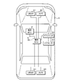
- FIG. It is explanatory drawing of arrangement of an integrated ECU, an individual ECU and the like. It is a block diagram which shows the main part structure of the integrated ECU. It is a chart which shows the transmission ratio table corresponding to a running state. It is a chart which shows the transmission ratio table corresponding to the parking state. It is a figure which shows the transmission ratio table corresponding to a standby state. It is a block diagram which shows the composition of the main part of an individual ECU. It is a flowchart which shows the procedure of updating the state of a vehicle. It is a flowchart which shows the procedure of image data transmission processing.
- the senor Normally, the sensor repeatedly outputs the data.
- the communication device described in Patent Document 1 transmits, for example, each time data is acquired from a sensor, the acquired data to a second communication device via a communication line.
- the importance of the data depends on the condition of the vehicle.
- the data output by the sensor is image data of an image showing the front side of the vehicle
- the importance of the data is high when the vehicle is running.
- the data is less important when the vehicle is parked.
- the communication device transmits data each time data is acquired from the sensor, the number of data transmitted by the communication device per unit time does not change even if the importance of the data is low. Therefore, there is a problem that efficient data transmission cannot be realized.
- the communication device is a communication device mounted on a vehicle and includes a processing unit that executes processing, and the processing unit repeatedly acquires and acquires vehicle data related to the vehicle. Instructs the transmission of related data related to the vehicle data, and determines the transmission ratio of the number of related data to be transmitted among the number of related data obtained by acquisition or generation according to the state of the vehicle. It is determined whether or not to transmit the related data obtained by acquisition or generation according to the transmission ratio.
- the related data is vehicle data or data generated based on a plurality of vehicle data.
- the number of types of the related data is two or more, and the processing unit has the types of related data obtained by acquisition or generation and the state of the vehicle.
- the transmission ratio is determined according to the above.
- the related data is transmitted via a communication line
- the processing unit determines the type of the related data obtained by acquisition or generation, the state of the vehicle, and the state of the vehicle.
- the transmission ratio is determined according to the load value of the communication line.
- the plurality of types of related data include the first type of related data and the second type of related data, and the state of the vehicle is the first state.
- the transmission ratio for the first type of related data is larger than the transmission ratio for the second type of related data, and when the vehicle is in the second state, the transmission ratio for the first type of related data. Is smaller than the transmission ratio for the second type of related data.
- the communication device includes a receiving unit for receiving request data requesting additional transmission of the related data, and the processing unit receives the requested data when the receiving unit receives the requested data. Instructs the transmission of related data that was not transmitted according to the judgment.
- the communication device includes a receiving unit for receiving request data requesting additional transmission of the related data, and the processing unit receives the requested data when the receiving unit receives the requested data. Directs transmission of relevant data obtained by acquisition or generation, regardless of the condition of the vehicle.
- the actuator is provided with an output unit that outputs a control signal indicating the operation of the actuator, and the actuator is used as an element used by the processing unit to determine the transmission ratio. Types are included.
- the state of the vehicle is whether or not the ignition switch is on, whether or not the parking brake is on, and whether or not the speed of the vehicle is zero. Determined based on the heel.
- a step of determining the transmission ratio occupied by the number of related data to be transmitted in the number of related data obtained by generation, and a step of determining whether or not to transmit the acquired related data according to the determined transmission ratio. Is executed by the computer.
- the computer program has a step of repeatedly acquiring vehicle data related to a vehicle, a step of instructing transmission of related data related to the acquired vehicle data, and acquisition or acquisition according to the state of the vehicle.
- the communication device communication method and computer program according to the above aspect, it is determined whether or not to transmit the related data according to the transmission ratio according to the state of the vehicle. Therefore, efficient transmission of related data is realized.
- the transmission ratio is the ratio of the number of transmitted related data to the number of acquired vehicle data (related data). be.
- the transmission ratio is 20%, for example, one of the five continuously acquired vehicle data (related data) is transmitted.
- the transmission ratio is the ratio of the number of related data transmitted to the number of related data generated.
- the transmission ratio is 20%, for example, one of the five continuously generated related data is transmitted.
- the transmission ratio is determined not only according to the state of the vehicle but also according to the type of related data. Therefore, more efficient transmission of related data is realized.
- the transmission ratio is determined not only according to the state of the vehicle and the type of related data, but also according to the load value of the communication line. Therefore, more efficient transmission of related data is realized.
- the communication device there are a plurality of states including the first state and the second state depending on the state of the vehicle.
- the transmission ratio of the first type of related data is larger than the transmission ratio of the second type of related data.
- the transmission ratio for the first type of related data is smaller than the transmission ratio for the second type of related data.
- the importance of the first type of related data is high.
- the second state the importance of the second type of related data is high.
- the relevant data obtained by acquisition or generation is sequentially transmitted.
- the type of actuator is included in the element used for determining the transmission ratio.
- the state of the vehicle is based on whether the ignition switch is on, the parking brake is on, and the speed of the vehicle is zero. It is determined.
- FIG. 1 is a block diagram showing a configuration of a main part of the communication system 1 in the first embodiment.
- the communication system 1 is mounted on the vehicle C.
- the communication system 1 includes an integrated ECU 2, a plurality of individual ECUs 3, two cameras 40, two LIDAR 41s, a door switch 42, a door motor 43, a sensor 50, and an actuator 51.
- ECU is an abbreviation for Electronic Control Unit.
- the plurality of individual ECUs 3 include individual ECUs 3a and 3b. Each individual ECU 3 is connected to the integrated ECU 2 by a communication line L.
- the individual ECU 3a is separately connected to two cameras 40, two LIDAR 41s, a door switch 42, and a door motor 43.
- the individual ECU 3b is separately connected to the sensor 50 and the actuator 51.
- FIG. 2 is an explanatory diagram of the arrangement of the integrated ECU 2 and the individual ECU 3a and the like.
- Each of the two cameras 40 is arranged on the front side and the rear side in the vehicle C.
- the two LIDAR 41s are arranged on the front side and the rear side in the vehicle C.
- Each of the door switch 42 and the door motor 43 is arranged in the door of the vehicle C.
- the integrated ECU 2 and the individual ECU 3a are arranged in the central portion of the vehicle C. In FIG. 2, the individual ECU 3b, the sensor 50, and the actuator 51 are not shown.
- the camera 40 arranged on the front side in the vehicle C repeatedly shoots the front side of the vehicle C.
- the camera 40 arranged on the rear side in the vehicle C repeatedly photographs the rear side of the vehicle C.
- Each camera 40 generates image data each time a picture is taken.
- Each camera 40 outputs the generated image data to the individual ECU 3a each time the image data is generated.
- the LIDAR 41 arranged on the front side in the vehicle C intermittently emits a laser beam to the front side of the vehicle C, and measures the laser light reflected by an object arranged on the front side of the vehicle C.
- the LIDAR 41 arranged on the rear side in the vehicle C intermittently emits a laser beam to the rear side of the vehicle C, and measures the laser light reflected by an object arranged on the rear side of the vehicle C.
- Each LIDAR 41 repeatedly generates point cloud data indicating a distance and an angle with respect to an object arranged outside the vehicle C.
- Each LIDAR 41 outputs to the individual ECU 3a each time the point cloud data is generated.
- Each of the camera 40 and the LIDAR 41 is one of a plurality of sensors mounted on the vehicle C.
- the individual ECU 3a transmits a part or all of the image data acquired from one camera 40 to the integrated ECU 2 via the communication line L.
- the individual ECU 3a transmits a part or all of the point cloud data acquired from one LIDAR 41 to the integrated ECU 2 via the communication line L.
- Each of the image data and the point cloud data is vehicle data related to vehicle C and related data related to vehicle data.
- the door switch 42 can be switched on or off by the user.
- the door motor 43 locks or unlocks the door of the vehicle C based on the state of the door switch 42 regarding on and off.
- the door switch 42 repeatedly outputs the first door data indicating the state of the door switch 42 regarding on and off to the individual ECU 3a.
- the first door data indicates on or off.
- Each door switch 42 is one of a plurality of sensors mounted on the vehicle C.
- the individual ECU 3a generates the second door data based on the input K first door data each time the K first door data is input from the door switch 42.
- the second door data also shows the state of the door switch 42 with respect to on and off.
- K is an integer of 2 or more and is a constant value.
- the state of the door switch 42 is determined based on the three states indicated by the three first door data.
- the individual ECU 3a determines, for example, the state of the door switch 42, which is the most state among the three states indicated by the three first door data. This process is a so-called filter process.
- the second door data indicates a state determined by the individual ECU 3a.
- the individual ECU 3a transmits a part or all of the generated second door data to the integrated ECU 2 via the communication line L.
- the first door data is vehicle data.
- the second door data is related data.
- the image data, the point cloud data, and the second door data are three types of related data.
- the individual ECU 3a functions as a communication device.
- the individual ECU 3a outputs a control signal to the door motor 43.
- the control signal output to the door motor 43 indicates that the door is locked or unlocked.
- the door motor 43 locks the door when the input control signal indicates locking.
- the door motor 43 unlocks the door when the input control signal indicates unlocking.
- the sensor 50 shown in FIG. 1 detects the vehicle C and repeatedly generates vehicle data.
- vehicle data generated by the sensor 50 include image data, point group data, first door data, speed data, ignition data, parking brake data, and the like.
- the speed data indicates the speed of the vehicle C.
- the ignition data indicates whether or not the ignition switch of the vehicle C is on. The ignition switch is switched on or off when the engine of the vehicle C is switched on or off.
- the parking brake data indicates whether the parking brake is on or not. The parking brake is used to keep the vehicle C stationary.
- the sensor 50 outputs the generated vehicle data to the individual ECU 3b each time the vehicle data is generated.
- the individual ECU 3b transmits the vehicle data input from the sensor 50 to the integrated ECU 2 as related data via the communication line L.
- the individual ECU 3b transmits a part or all of the plurality of vehicle data (related data) input from the sensor 50 to the integrated ECU 2.
- the individual ECU 3b generates one related data based on N vehicle data input from the sensor 50. N is an integer of 2 or more and is a constant value.
- the individual ECU 3b transmits the generated related data to the integrated ECU 2 via the communication line L.
- the individual ECU 3b transmits a part or all of the generated related data to the integrated ECU 2.
- the actuator 51 operates with respect to the vehicle C.
- the actuator 51 is a lamp
- the actuator 51 turns on or off.
- the individual ECU 3b outputs a control signal indicating the operation of the actuator 51 to the actuator 51.
- a control signal is input from the individual ECU 3b, the actuator 51 performs the operation indicated by the input control signal.
- the integrated ECU 2 receives a plurality of types of related data from a plurality of individual ECUs 3.
- the plurality of types of related data received by the integrated ECU 2 include image data, point cloud data, second door data, speed data, ignition data, and parking brake data.
- the integrated ECU 2 determines the operation of the door motor 43 and the actuator 51 based on one or more related data received from one or more individual ECUs 3.
- the integrated ECU 2 transmits instruction data indicating the determined operation to one or more individual ECUs 3 via one or more communication lines L.
- the individual ECU 3a receives the instruction data
- the individual ECU 3a outputs a control signal to the door motor 43.
- the operation indicated by the control signal is the operation indicated by the received instruction data.
- the individual ECU 3b receives the instruction data
- the individual ECU 3b outputs a control signal to the actuator 51.
- the operation indicated by the control signal is the operation indicated by the received instruction data.
- one individual ECU 3 transmits a part of the related data obtained by acquisition or generation to the integrated ECU 2.
- the integrated ECU 2 when the integrated ECU 2 requires one or more related data that are not scheduled to be transmitted, the integrated ECU 2 sends the request data requesting additional transmission of the one or more related data that is not scheduled to be transmitted to the individual ECU 3. Send.
- the individual ECU 3 receives the request data, the individual ECU 3 transmits one or a plurality of related data that are not scheduled to be transmitted to the integrated ECU 2.
- the integrated ECU 2 stores vehicle state data indicating the state of the vehicle C.
- the integrated ECU 2 repeatedly determines the state of the vehicle C based on the speed data, the ignition data, and the parking brake data received as related data.
- the integrated ECU 2 updates the state of the vehicle C indicated by the vehicle state data each time the state of the vehicle C is determined.
- Examples of the state of the vehicle C include a running state, a parking state, and a standby state.
- the traveling state is a state in which the ignition switch is on, the parking brake is off, and the speed of the vehicle C exceeds zero.
- the parking state is a state in which the ignition switch is on, the parking brake is on, and the speed of the vehicle C is zero.
- the standby state is a state in which the ignition switch is off, the parking brake is on, and the speed of the vehicle C is zero.
- the integrated ECU 2 transmits the vehicle state data to a plurality of individual ECUs 3 including the individual ECUs 3a and 3b. Vehicle state data is also stored in each individual ECU 3. Each individual ECU 3 rewrites the stored vehicle state data into the vehicle state data received from the integrated ECU 2. Each individual ECU 3 adjusts the transmission ratio of the number of related data to be transmitted to the integrated ECU 2 among the number of related data obtained by acquisition or generation for each type of related data according to the state of the vehicle C. The unit of transmission ratio is percentage.
- the communication protocol for communication via the communication line L is, for example, an Ethernet (registered trademark) communication protocol.
- the number of each of the individual ECUs 3a and 3b included in the communication system 1 is not limited to 1, and may be 2 or more.
- the actuator connected to the individual ECU 3a is not limited to the door motor 43, and may be an actuator different from the door motor 43.
- the number of actuators connected to the individual ECU 3a is not limited to 1, and may be 2 or more.
- the number of actuators connected to the individual ECU 3b is not limited to 1, and may be 2 or more.
- the number of sensors connected to the individual ECU 3a is not limited to 5, and may be 1 to 4, or 6 or more.
- the number of sensors 50 connected to the individual ECU 3b is not limited to 1, and may be 2 or more.
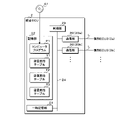
- FIG. 3 is a block diagram showing a configuration of a main part of the integrated ECU 2.
- the integrated ECU 2 has a plurality of communication units 20, a temporary storage unit 21, a storage unit 22, and a control unit 23. These are connected to the internal bus 24.
- the plurality of communication units 20 include communication units 20a and 20b.
- the communication unit 20a is further connected to the individual ECU 3a by the communication line L.
- the communication unit 20b is further connected to the individual ECU 3b by the communication line L.
- the communication unit 20a receives image data, point cloud data, and second door data from the individual ECU 3a.
- the communication unit 20a transmits instruction data, request data, and vehicle state data to the individual ECU 3a according to the instructions of the control unit 23.
- the communication unit 20b receives the related data from the individual ECU 3b.
- the communication unit 20b transmits instruction data, request data, and vehicle state data to the individual ECU 3b according to the instructions of the control unit 23.
- the temporary storage unit 21 is a volatile memory. When the power supply to the integrated ECU 2 is stopped, the data stored in the temporary storage unit 21 is erased.
- the control unit 23 executes a plurality of data processes related to the temporary storage unit 21.
- the plurality of data processes include writing data, reading data, and the like.
- the storage unit 22 is a non-volatile memory.
- the data stored in the storage unit 22 is retained regardless of whether or not power is supplied to the integrated ECU 2.
- the control unit 23 executes a plurality of data processing related to the storage unit 22.
- the plurality of data processes include writing data, reading data, and the like.
- the storage unit 22 stores vehicle state data indicating the state of the vehicle C.
- the state of the vehicle C indicated by the vehicle state data is updated by the control unit 23.
- the storage unit 22 stores three transmission ratio tables T1, T2, and T3 showing transmission ratios of the three types of related data.
- the transmission ratio table T1 shows the transmission ratio of the second door data, the image data, and the point cloud data. Similar to the transmission ratio table, the transmission ratios of the second door data, the image data, and the point cloud data are shown in each of the transmission ratio tables T2 and T3.
- the transmission ratio table T1 corresponds to the traveling state.
- the transmission ratio table T2 corresponds to the parking state.
- the transmission ratio table T3 corresponds to the standby state.
- the transmission ratio of the second door data is the ratio of the number of the second door data transmitted to the integrated ECU 2 to the number of the second door data generated by the individual ECU 3a.
- the image data transmission ratio is the ratio of the number of image data transmitted to the integrated ECU 2 to the number of image data acquired by the individual ECU 3a from one camera 40.
- the point cloud data transmission ratio is the ratio of the number of point cloud data transmitted to the integrated ECU 2 to the number of point cloud data acquired by the individual ECU 3a from one LIDAR 41, similar to the transmission ratio of image data. ..
- FIG. 4 is a chart showing the transmission ratio table T1 corresponding to the traveling state. As described above, when the ignition switch is on, the parking brake is off, and the speed of the vehicle C exceeds zero, the state of the vehicle C is a running state. As shown in FIG. 4, the transmission ratio of the second door data is 50%. Therefore, half of the plurality of second door data generated by the individual ECU 3a is transmitted to the integrated ECU 2.
- the transmission ratio of image data and point cloud data is 100%. Therefore, all the image data acquired from one camera 40 is transmitted to the integrated ECU 2. All the point cloud data acquired from one LIDAR 41 is transmitted to the integrated ECU 2. In the design of vehicle C, the importance of the second door data is medium. The importance of image data and point cloud data is great. Therefore, when the state of the vehicle C is the traveling state, the transmission ratios of the image data and the point cloud data are larger than the transmission ratios of the second door data.
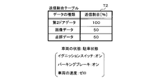
- FIG. 5 is a chart showing the transmission ratio table T2 corresponding to the parking state. As described above, when the ignition switch is on, the parking brake is on, and the speed of the vehicle C is zero, the state of the vehicle C is the parked state. As shown in FIG. 5, the transmission ratio of the second door data is 100%. Therefore, all the second door data generated by the individual ECU 3a is transmitted to the integrated ECU 2.
- the transmission ratio of image data and point cloud data is 50%. Therefore, half of the plurality of image data acquired from one camera 40 is transmitted to the integrated ECU 2. Half of the plurality of point cloud data acquired from one LIDAR 41 is transmitted to the integrated ECU 2. In the design of vehicle C, the importance of the second door data is great. The importance of image data and point cloud data is medium. Therefore, when the vehicle C is in the parked state, the transmission ratios of the image data and the point cloud data are smaller than the transmission ratios of the second door data.
- FIG. 6 is a chart showing a transmission ratio table T3 corresponding to the standby state. As described above, when the ignition switch is off, the parking brake is on, and the speed of the vehicle C is zero, the state of the vehicle C is the standby state. As shown in FIG. 6, the transmission ratio of the second door data is 50%. Therefore, half of the plurality of second door data generated by the individual ECU 3a is transmitted to the integrated ECU 2.
- the transmission ratio of image data and point cloud data is 20%. Therefore, one-fifth of the plurality of image data acquired from one camera 40 is transmitted to the integrated ECU 2. One-fifth of the plurality of point cloud data acquired from one LIDAR 41 is transmitted to the integrated ECU 2.
- the importance of the second door data is medium. The importance of image data and point cloud data is small. Therefore, when the vehicle C is in the standby state, the transmission ratios of the image data and the point cloud data are smaller than the transmission ratios of the second door data.
- the control unit 23 can recognize the transmission ratio of the second door data, the image data, and the point cloud data based on the transmission ratio table corresponding to the state of the vehicle C indicated by the vehicle state data.
- the computer program P1 is further stored in the storage unit 22.
- the control unit 23 has a processing element for executing processing, for example, a CPU (Central Processing Unit).
- the processing element of the control unit 23 executes the first update process, the image data storage process, the point cloud data storage process, the second door data storage process, the related data storage process, and the instruction data transmission process. And so on.
- the first update process is a process for updating the state of the vehicle C indicated by the vehicle state data stored in the storage unit 22.
- the image data storage process is a process of writing image data received from the individual ECU 3a to the temporary storage unit 21.
- the point cloud data storage process is a process of writing the point cloud data received from the individual ECU 3a to the temporary storage unit 21.
- the second door data storage process is a process of writing the second door data received from the individual ECU 3a to the temporary storage unit 21.
- the related data storage process is a process of writing the related data received from the individual ECU 3b to the temporary storage unit 21.
- the instruction data transmission process is a process of transmitting instruction data to one or a plurality of individual ECUs 3. Details of the first update process, the image data storage process, the point cloud data storage process, the second door data storage process, the related data storage process, and the instruction data transmission process will be described later.
- the computer program P1 may be stored in the non-temporary storage medium A1 so that the processing element of the control unit 23 can read it.
- the computer program P1 read from the storage medium A1 by a reading device (not shown) is written in the storage unit 22.
- the storage medium A1 is an optical disk, a flexible disk, a magnetic disk, a magnetic disk disk, a semiconductor memory, or the like.
- the optical disk is a CD (Compact Disc) -ROM (Read Only Memory), a DVD (Digital Versatile Disc) -ROM, or a BD (Blu-ray (registered trademark) Disc).
- the magnetic disk is, for example, a hard disk.
- the computer program P1 may be downloaded from an external device (not shown) connected to a communication network (not shown), and the downloaded computer program P1 may be written in the storage unit 22.
- control unit 23 the number of processing elements possessed by the control unit 23 is not limited to 1, and may be 2 or more.
- the plurality of processing elements cooperate to perform the first update processing, the image data storage processing, the point cloud data storage processing, the second door data storage processing, the related data storage processing, and the like.
- the instruction data transmission process or the like may be executed.
- FIG. 7 is a block diagram showing a configuration of a main part of the individual ECU 3a.
- the individual ECU 3a includes a communication unit 30, an input unit 31, an output unit 32, a temporary storage unit 33, a storage unit 34, and a control unit 35. These are connected to the internal bus 36.
- the communication unit 30 is further connected to the communication unit 20 of the integrated ECU 2 by the communication line L.
- the input unit 31 is further connected to two cameras 40, two LIDAR 41s and a door switch 42.
- the output unit 32 is further connected to the door motor 43.
- the communication unit 30 transmits image data, point cloud data, and second door data to the communication unit 20 of the integrated ECU 2 via the communication line L according to the instructions of the control unit 35.
- the communication unit 30 receives instruction data, request data, and vehicle state data from the communication unit 20 of the integrated ECU 2.
- the communication unit 30 functions as a receiving unit.
- the input unit 31 is an interface. Image data is repeatedly input to the input unit 31 from each camera 40. Point cloud data is repeatedly input to the input unit 31 from each LIDAR 41. The first door data is repeatedly input to the input unit 31 from the door switch 42.
- the output unit 32 is an interface. The output unit 32 outputs a control signal to the door motor 43 according to the instruction of the control unit 35. As described above, the door motor 43 performs the operation indicated by the input control signal.
- the temporary storage unit 33 is a volatile memory. When the power supply to the individual ECU 3a is stopped, the data stored in the temporary storage unit 33 is erased.
- the control unit 35 executes a plurality of data processes related to the temporary storage unit 33.
- the plurality of data processes include writing data, reading data, and the like.
- the storage unit 34 is a non-volatile memory.
- the data stored in the storage unit 22 is retained regardless of whether or not power is supplied to the integrated ECU 2.
- the control unit 23 executes a plurality of data processing related to the storage unit 22.
- the plurality of data processes include writing data, reading data, and the like.
- the storage unit 34 stores vehicle state data indicating the state of the vehicle C.
- the state of the vehicle C indicated by the vehicle state data is updated by the control unit 35.
- the storage unit 34 stores three transmission ratio tables T1, T2, and T3 showing transmission ratios of the three types of related data.
- the computer program P2 is further stored in the storage unit 34.
- the control unit 35 has a processing element that executes processing, for example, a CPU.
- the control unit 35 functions as a processing unit.
- the processing element of the control unit 35 executes the computer program P2 to perform a second update process, an image data transmission process, a point cloud data transmission process, a second door data transmission process, an image data addition transmission process, and a point cloud data addition process.
- the transmission process, the second door data addition transmission process, the operation control process, and the like are executed.
- the second update process is a process of rewriting the vehicle state data stored in the storage unit 34 into the vehicle state data received by the communication unit 30.
- the image data transmission process is a process of transmitting image data to the communication unit 20 of the integrated ECU 2.
- the point cloud data transmission process is a process of transmitting point cloud data to the communication unit 20 of the integrated ECU 2.
- the second door data transmission process is a process of transmitting the second door data to the communication unit 20 of the integrated ECU 2.
- the image data additional transmission process is a process of additionally transmitting image data to the communication unit 20 of the integrated ECU 2.
- the point cloud data additional transmission process is a process of additionally transmitting the point cloud data to the communication unit 20 of the integrated ECU 2.
- the second door data additional transmission process is a process of additionally transmitting the second door data to the communication unit 20 of the integrated ECU 2.
- the operation control process is a process of causing the door motor 43 to perform the operation indicated by the instruction data received by the communication unit 30. Details of the second update process, image data transmission process, point cloud data transmission process, second door data transmission process, image data additional transmission process, point cloud data additional transmission process, second door data additional transmission process, and operation control process. Will be described later.
- the computer program P2 may be stored in the non-temporary storage medium A2 so that the processing element of the control unit 35 can read it.
- the computer program P2 read from the storage medium A2 by a reading device (not shown) is written in the storage unit 34.
- the storage medium A2 is an optical disk, a flexible disk, a magnetic disk, a magnetic disk disk, a semiconductor memory, or the like.
- the computer program P2 may be downloaded from an external device (not shown) connected to a communication network (not shown), and the downloaded computer program P2 may be written in the storage unit 34.
- control unit 35 the number of processing elements possessed by the control unit 35 is not limited to 1, and may be 2 or more.
- the plurality of processing elements cooperate to perform vehicle state update processing, image data storage processing, point cloud data storage processing, second door data storage processing, related data storage processing, and The instruction data transmission process or the like may be executed.
- ⁇ Operation control of door motor 43 and actuator 51 In the operation control of the door motor 43 and the actuator 51, the control unit 23 of the integrated ECU 2 executes the instruction data transmission process, and the control unit 35 of the individual ECU 3a executes the operation control process. In the instruction data transmission process, the control unit 23 of the integrated ECU 2 determines the operation of the door motor 43 or the actuator 51 based on one or more related data received by one or more communication units 20 in the instruction data transmission process. .. When the control unit 23 determines the operation of the door motor 43, the control unit 23 instructs the communication unit 20a to transmit instruction data indicating the determined operation to the communication unit 30 of the individual ECU 3a.
- the control unit 35 of the individual ECU 3a instructs the output unit 32 to output the control signal to the door motor 43 when the communication unit 30 receives the instruction data.
- the operation indicated by the control signal is the operation indicated by the instruction data received by the communication unit 30.
- the door motor 43 executes the operation determined by the control unit 23 of the integrated ECU 2.
- the control unit 23 of the integrated ECU 2 determines the operation of the actuator 51, it instructs the communication unit 20b to transmit the instruction data indicating the determined operation to the individual ECU 3b.
- the individual ECU 3b receives the instruction data, the individual ECU 3b outputs a control signal to the actuator 51.
- the operation indicated by the control signal is the operation indicated by the instruction data received by the individual ECU 3b.
- the actuator 51 performs the operation determined by the control unit 23 of the integrated ECU 2.
- the plurality of individual ECUs 3 include one or a plurality of individual ECUs 3b. For each of the one or more individual ECUs 3b, the individual ECU 3b repeatedly transmits the related data regarding the vehicle data input from the sensor 50 to the communication unit 20b of the integrated ECU 2. The one or more individual ECUs 3b transmit a plurality of related data including speed data, ignition data and parking brake data to the communication unit 20b of the integrated ECU 2.
- the control unit 23 of the integrated ECU 2 stores the related data received by the communication unit 20b in the temporary storage unit 21.
- the plurality of types of related data stored in the temporary storage unit 21 are used, for example, when the control unit 23 determines the operation of the door motor 43 or the actuator 51. Further, the speed data, the ignition data, and the parking brake data stored in the temporary storage unit 21 are used when determining the state of the vehicle C.
- the control unit 23 of the integrated ECU 2 transmits the request data to the individual ECU 3b when one or more related data that are not scheduled to be transmitted are required.
- the individual ECU 3b receives the request data
- the individual ECU 3b transmits one or a plurality of related data that are not scheduled to be transmitted to the communication unit 20b of the integrated ECU 2.
- the control unit 23 of the integrated ECU 2 stores the one or more related data received by the communication unit 20b in the temporary storage unit 21.
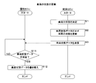
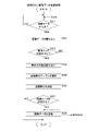
- FIG. 8 is a flowchart showing a procedure for updating the state of the vehicle C.
- the control unit 23 of the integrated ECU 2 executes the first update process
- the control unit 35 of the individual ECU 3a executes the second update process.
- the control unit 23 of the integrated ECU 2 periodically executes the first update process.
- the control unit 23 determines the state of the vehicle C based on the speed data, the ignition data, and the parking brake data received by one or more communication units 20 (step S1).
- the state of the vehicle C determined by the control unit 23 is one of a traveling state, a parking state, and a standby state.
- step S1 the speed of the vehicle C indicated by the speed data, the state of the ignition switch indicated by the ignition data, and the state of the parking brake indicated by the parking brake data are used.
- the method for determining the state of the vehicle C based on the speed of the vehicle C, the state of the ignition switch, and the state of the parking brake is as described above.
- the control unit 23 updates the state of the vehicle C indicated by the vehicle state data stored in the storage unit 22 to the state determined in step S1 (step S2).
- the control unit 23 instructs a plurality of communication units 20 to transmit the vehicle state data stored in the storage unit 22 to the plurality of individual ECUs 3 (step S3).
- the plurality of communication units 20 include communication units 20a and 20b.
- the plurality of individual ECUs 3 include individual ECUs 3a and 3b.
- the control unit 23 ends the first update process.
- the control unit 35 of the individual ECU 3a first determines whether or not the communication unit 30 has received the vehicle status data (step S11). When the control unit 35 determines that the vehicle state data has not been received (S11: NO), the control unit 35 executes step S11 again and waits until the communication unit 30 receives the vehicle state data. When the control unit 35 determines that the communication unit 30 has received the vehicle state data (S11: YES), the control unit 35 rewrites the vehicle state data stored in the storage unit 34 into the vehicle state data received by the communication unit 30 (S11: YES). Step S12), the second update process is terminated. After finishing the second update process, the control unit 35 executes the second update process again and waits until the communication unit 30 receives the vehicle state data.
- the individual ECU 3b When the individual ECU 3b receives the vehicle state data from the communication unit 20b of the integrated ECU 2, the individual ECU 3b rewrites the vehicle state data stored in the individual ECU 3b into the received vehicle state data. As described above, the state of the vehicle C indicated by the vehicle state data stored in the integrated ECU 2 and the individual ECUs 3a and 3b is periodically updated.
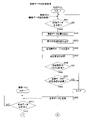
- FIG. 9 is a flowchart showing the procedure of the image data transmission process.
- the value of the image flag is stored in the storage unit 34.
- the value of the image flag is zero or one.
- the control unit 35 changes the value of the image flag to zero or one.
- the control unit 35 of the individual ECU 3a separately executes two image data transmission processes corresponding to the two cameras 40.
- the image data transmission process corresponding to one of the cameras 40 will be described.
- the two image data transmission processes are executed in the same manner.
- control unit 35 determines whether or not the image data has been input from the camera 40 to the input unit 31 (step S21).
- the image data input to the input unit 31 is acquired by the control unit 35.
- the image data input to the input unit 31 is vehicle data.
- control unit 35 determines that the image data has not been input (S21: NO)
- the control unit 35 executes step S21 again and waits until the image data is input from the camera 40 to the input unit 31.
- control unit 35 determines that the image data has been input (S21: YES)
- the control unit 35 writes the input image data to the temporary storage unit 21 (step S22).
- control unit 35 determines whether or not the value of the image flag is zero (step S23).
- the control unit 35 determines that the value of the image flag is zero (S23: YES)
- the control unit 35 reads out the state of the vehicle C indicated by the vehicle state data from the storage unit 34 (step S24).
- the control unit 35 selects a transmission ratio table corresponding to the state of the vehicle C read in step S24 from the three transmission ratio tables T1, T2, and T3 (step S25).
- each of the transmission ratio tables T1, T2, and T3 corresponds to a running state, a parking state, and a standby state.
- control unit 35 determines the transmission ratio of the image data to be the transmission ratio of the image data indicated by the transmission ratio table selected in step S25 (step S26). After that, the control unit 35 determines whether or not to transmit the image data acquired from the input unit 31 to the communication unit 20 of the integrated ECU 2 as related data according to the transmission ratio determined in step S26 (step S27). When the control unit 35 determines that the value of the image flag is 1 (S23: NO) or determines that the image data is to be transmitted (S27: YES), the control unit 35 instructs the communication unit 30 to acquire the image. Data is transmitted to the communication unit 20 of the integrated ECU 2 via the communication line L (step S28). The control unit 35 ends the image data transmission process when it is determined that the image data is not transmitted (S27: NO) or after the step S28 is executed.
- the control unit 35 executes the image data transmission process again and waits until the image data is input to the input unit 31. Therefore, the control unit 35 repeatedly acquires the image data.
- the value of the image flag is zero, it is determined whether or not to transmit the image data so that the actual transmission ratio becomes the transmission ratio determined in step S26 unless the state of the vehicle C is changed. Will be done.
- the communication unit 30 transmits the input image data to the communication unit 20 of the integrated ECU 2 each time the image data is input to the input unit 31 regardless of the state of the vehicle C. ..
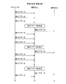
- FIG. 10 is a sequence diagram showing transmission of image data in a traveling state.
- FIG. 10 shows an example in which the value of the image flag is zero.
- the control unit 35 of the individual ECU 3a selects the transmission ratio table T1.
- the transmission ratio of the image data is 100%. Therefore, as shown in FIG. 10, in the individual ECU 3a, each time image data is input from one camera 40 to the input unit 31, the communication unit 20 transmits the input image data to the communication unit 20 of the integrated ECU 2. ..
- FIG. 11 is a sequence diagram showing transmission of image data in a parked state.
- FIG. 11 shows an example in which the value of the image flag is zero.
- the control unit 35 of the individual ECU 3a selects the transmission ratio table T2.
- the transmission ratio of the image data is 50%. Therefore, as shown in FIG. 11, in the individual ECU 3a, the communication unit 30 transmits half of the plurality of image data in which image data is input from one camera 40 to the input unit 31 to the communication unit 20 of the integrated ECU 2.
- the communication unit 20 transmits every other image data to the communication unit 20 of the integrated ECU 2.
- the method of transmitting the image data by the communication unit 20 is not limited to the method of transmitting the image data every other time. If the transmission ratio is 50%, there is no problem. Therefore, for example, the communication unit 30 transmits two image data continuously input from the camera 40 to the communication unit 20 of the integrated ECU 2. Next, the communication unit 30 does not transmit two image data continuously input from the camera 40.
- the communication unit 30 may repeat this series of operations.
- the control unit 35 of the individual ECU 3a selects the transmission ratio table T3. As shown in FIG. 6, in the transmission ratio table T3, the transmission ratio of the image data is 20%. Therefore, in the individual ECU 3a, the communication unit 30 transmits one-fifth of the plurality of image data whose image data is input from one camera 40 to the input unit 31 to the communication unit 20 of the integrated ECU 2. For example, the communication unit 20 transmits image data every four to the communication unit 20 of the integrated ECU 2.
- Image data is not filtered.
- the image data is vehicle data and related data.
- the point cloud data is also not filtered.
- Point cloud data is also vehicle data and related data. Therefore, the point cloud data transmission process is executed by the control unit 35 of the individual ECU 3a in the same manner as the image data transmission process.
- the value of the point cloud flag is stored in the storage unit 34.
- the value of the point cloud flag is zero or one.
- the control unit 35 changes the value of the point cloud flag to zero or one.
- the control unit 35 of the individual ECU 3a separately executes two point cloud data transmission processes corresponding to the two LIDAR 41s. In the description of the image data transmission process, the camera 40, the image data and the image flag are replaced with the LIDAR 41, the point cloud data and the point cloud flag. This makes it possible to explain the point cloud data transmission process.
- FIG. 12 is a flowchart showing the procedure of the door data transmission process.
- the value of the door flag is stored in the storage unit 34.
- the value of the door flag is zero or one.
- the control unit 35 changes the value of the door flag to zero or one.
- the second door data is generated based on the K door data.
- K is an integer of 2 or more and is a constant value.
- the storage unit 34 stores the number of data of the first door data continuously input from the door switch 42 to the input unit 31.
- the control unit 35 determines whether or not the first door data has been input from the door switch 42 (step S31).
- the first door data input to the input unit 31 is acquired by the control unit 35.
- the control unit 35 executes step S31 again and waits until the first door data is input to the input unit 31.
- the control unit 35 increments the number of data by 1 (step S32) and determines whether or not the number of data is K (step S33). ..
- step S31 When the control unit 35 determines that the number of data is not K (S33: NO), the control unit 35 executes step S31 again and waits until the number of data becomes K.
- the control unit 35 determines that the number of data is K (S33: YES)
- the control unit 35 generates the second door data based on the acquired K first door data (step S34).
- the second door data generated in step S34 is, for example, data indicating the most state among the K states indicated by the K first door data.
- step S35 After executing step S34, the control unit 35 sets the number of data to zero (step S35).
- the control unit 35 writes the second door data generated in step S34 to the temporary storage unit 33 (step S36).
- step S37 the control unit 35 determines whether or not the value of the door flag is zero (step S37).
- the control unit 35 reads out the state of the vehicle C indicated by the vehicle state data from the storage unit 34 (step S38).
- step S38 the control unit 35 selects a transmission ratio table corresponding to the state of the vehicle C read in step S38 from the three transmission ratio tables T1, T2, and T3 (step S39).
- the control unit 35 determines the transmission ratio of the second door data to be the transmission ratio of the second door data indicated by the transmission ratio table selected in step S39 (step S40). After that, the control unit 35 determines whether or not to transmit the second door data generated in step S34 to the communication unit 20 of the integrated ECU 2 according to the transmission ratio determined in step S40 (step S41). When the control unit 35 determines that the value of the door flag is 1 (S37: NO) or determines that the second door data is to be transmitted (S41: YES), the control unit 35 instructs the communication unit 30 to instruct step S34. The second door data generated in step 1 is transmitted to the communication unit 20 of the integrated ECU 2 via the communication line L (step S42). The control unit 35 ends the door data transmission process when it is determined that the second door data is not transmitted (S41: NO) or after the step S42 is executed.
- the control unit 35 executes the door data transmission process again and waits until K first door data are input to the input unit 31. Therefore, the control unit 35 repeatedly acquires the first door data.
- the value of the door flag is zero, it is determined whether or not to transmit the second door data so that the actual transmission ratio becomes the transmission ratio determined in step S40 unless the state of the vehicle C is changed. Is done.
- the communication unit 30 transmits the generated second door data to the communication unit 20 of the integrated ECU 2 each time the second door data is generated, regardless of the state of the vehicle C.
- FIG. 13 is a sequence diagram showing transmission of the second door data in the parked state.
- FIG. 13 shows an example in which K is 3 and the value of the door flag is zero.
- the control unit 35 is based on the input K first door data. Generate second door data.
- step S39 of the door data transmission process the control unit 35 of the individual ECU 3a selects the transmission ratio table T2. As shown in FIG. 5, in the transmission ratio table T2, the transmission ratio of the second door data is 100%. Therefore, as shown in FIG. 13, in the individual ECU 3a, each time the control unit 35 generates the second door data, the communication unit 20 transmits the second door data generated by the control unit 35 to the communication unit 20 of the integrated ECU 2. do.
- FIG. 14 is a sequence diagram showing transmission of the second door data in a traveling state.
- FIG. 14 shows an example in which K is 3 and the value of the door flag is zero.
- the control unit 35 generates the second door data each time K pieces of first door data are input from the door switch 42 to the input unit 31.
- the control unit 35 of the individual ECU 3a selects the transmission ratio table T1.
- the transmission ratio table T1 As shown in FIG. 4, in the transmission ratio table T1, the transmission ratio of the second door data is 50%. Therefore, as shown in FIG. 14, in the individual ECU 3a, the communication unit 30 transmits half of the plurality of second door data generated by the control unit 35 to the communication unit 20 of the integrated ECU 2.
- the communication unit 20 transmits every other second door data to the communication unit 20 of the integrated ECU 2.
- the method of transmitting the second door data by the communication unit 20 is not limited to the method of transmitting the second door data every other time. If the transmission ratio is 50%, there is no problem. Therefore, for example, the communication unit 30 transmits the two second door data continuously generated by the control unit 35 to the communication unit 20 of the integrated ECU 2. Next, the communication unit 30 does not transmit the two second door data continuously generated by the control unit 35.
- the communication unit 30 may repeat this series of operations.
- the control unit 35 of the individual ECU 3a selects the transmission ratio table T3. As shown in FIG. 6, in the transmission ratio table T3, the transmission ratio of the second door data is 50%. Therefore, in the individual ECU 3a, the communication unit 30 transmits half of the plurality of second door data generated by the control unit 35 to the communication unit 20 of the integrated ECU 2. For example, the communication unit 20 transmits every other second door data to the communication unit 20 of the integrated ECU 2.
- 15 and 16 are flowcharts showing a procedure for additional transmission of image data.
- the control unit 23 of the integrated ECU 2 executes the image data storage process.
- the control unit 35 of the individual ECU 3a executes the image data addition transmission process.
- the control unit 35 of the individual ECU 3a executes the image data transmission process. Therefore, the communication unit 30 repeatedly transmits the image data to the communication unit 30 of the integrated ECU 2.
- the control unit 23 of the integrated ECU 2 determines whether or not the communication unit 20a has received the image data from the communication unit 30 of the individual ECU 3a (step S51).
- the control unit 23 executes step S51 again and waits until the communication unit 20a receives the image data.
- the control unit 23 determines that the image data has been received by the communication unit 20a (S51: YES)
- the control unit 23 writes the image data received by the communication unit 20a to the temporary storage unit 21 (step S52).
- step S52 the control unit 23 reads out the state of the vehicle C indicated by the vehicle state data from the storage unit 22 (step S53).
- step S53 the control unit 23 selects a transmission ratio table corresponding to the state of the vehicle C read in step S53 from the transmission ratio tables T1, T2, and T3 (step S54).
- step S55 the control unit 23 refers to the transmission ratio corresponding to the image data in the transmission ratio table selected in step S54 (step S55), and determines whether or not the referred transmission ratio is less than 100% (step S55). Step S56).
- step S57 the control unit 23 determines whether or not additional transmission of one or more image data that is not scheduled to be transmitted is necessary.
- step S57 for example, when the situation around the vehicle C is a situation in which the importance of the image data is high, the control unit 23 determines that additional transmission of one or a plurality of image data is necessary.
- One or more image data that are not scheduled to be transmitted are not transmitted between the time when the previous image data is transmitted and the time when the next image data is transmitted when the value of the image flag is zero. It is one or a plurality of image data stored in the temporary storage unit 21 in the state of.
- the control unit 23 stores image data when it is determined that the transmission ratio is 100% (S56: NO) or when it is determined that additional transmission of one or more image data is not necessary (S57: NO). End the process.
- control unit 23 determines that additional transmission of one or more image data is necessary (S57: YES)
- the control unit 23 instructs the communication unit 20a to request additional transmission of one or more image data. Is transmitted (step S58).
- the control unit 35 of the individual ECU 3a determines whether or not the communication unit 30 has received the request data from the communication unit 20a of the integrated ECU 2 (step S71).
- the control unit 35 executes step S71 again and waits until the communication unit 30 receives the request data.
- Step S72 the control unit 35 determines whether or not all the image data not scheduled to be transmitted are already stored in the temporary storage unit 21.
- Step S73 the control unit 35 instructs the communication unit 30 to instruct all the image data that were not transmitted according to the determination in step S27 of the image data transmission process. Is transmitted to the communication unit 20a of the integrated ECU 2 via the communication line L (step S73). After executing step S73, the control unit 35 ends the image data addition transmission process.
- step S74 the control unit 35 of the individual ECU 3a instructs the communication unit 20 to transmit the acquired image data each time the image data is acquired from the camera 40, regardless of the state of the vehicle C.
- step S75 the control unit 23 determines whether or not all the image data that are not scheduled to be transmitted have been transmitted.
- control unit 35 determines that the transmission of all the image data has not been completed (S75: NO)
- the control unit 35 executes step S75 again and waits until the transmission of all the image data is completed.
- the control unit 23 changes the value of the image flag to zero (step S76), and ends the image data addition transmission process.
- the control unit 23 executes the image data addition transmission processing again, and waits until the communication unit 20a receives the request data.
- the control unit 23 of the integrated ECU 2 determines whether or not the communication unit 20a has received all the image data that is not scheduled to be transmitted after executing step S58 (step S59).
- step S59 the control unit 23 determines that all the image data not scheduled to be transmitted have been received (S59: NO)
- the control unit 23 executes step S59 again, and transmits all the image data not scheduled to be transmitted to the communication unit. Wait until 20a is received.
- control unit 35 determines that all the image data not scheduled to be transmitted has been received (S59: YES)
- the control unit 35 writes all the image data received by the communication unit 20a to the temporary storage unit 21 (step S60).
- the image data storage process is terminated. After finishing the image data storage process, the control unit 35 executes the image data storage process again and waits until the communication unit 20a receives the image data.
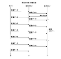
- FIG. 17 is a sequence diagram for explaining a first example of additional transmission of image data.
- FIG. 17 shows transmission of image data in a standby state.
- the transmission ratio table T3 corresponding to the standby state, as shown in FIG. 6, the transmission ratio of the image data is 20%.
- the communication unit 30 of the individual ECU 3a transmits one image data every four to the communication unit 20a of the integrated ECU 2.
- the control unit 35 of the individual ECU 3a writes all the image data input from one camera 40 into the temporary storage unit 33.
- the control unit 23 of the integrated ECU 2 determines that additional transmission of four image data that are not scheduled to be transmitted is necessary in the image data storage process.
- the communication unit 20 transmits the request data requesting the transmission of the four image data that are not scheduled to be transmitted to the communication unit 30 of the individual ECU 3a.
- the communication unit 20a of the integrated ECU 2 transmits the request data.
- the control unit 35 of the individual ECU 3a executes step S73.
- the communication unit 30 of the individual ECU 3a transmits four image data that are not scheduled to be transmitted to the communication unit 20 of the integrated ECU 2.
- four image data that are not scheduled to be transmitted are written in the temporary storage unit 33 of the integrated ECU 2.
- FIG. 18 is a sequence diagram for explaining a second example of additional transmission of image data.
- FIG. 18 shows the transmission of image data in a standby state, as in FIG.
- the communication unit 20a of the integrated ECU 2 transmits the request data before the four image data that are not scheduled to be transmitted are written to the temporary storage unit 33 of the individual ECU 3a.
- the control unit 35 of the individual ECU 3a executes step S74.
- the value of the image flag is changed to 1.
- the communication unit 30 of the individual ECU 3a is input to the input unit 31 each time image data is input from the camera 40 to the input unit 31, regardless of the state of the vehicle C.
- the input image data is transmitted to the communication unit 20 of the integrated ECU 2.
- four image data that were not scheduled to be transmitted are written in the temporary storage unit 33 of the integrated ECU 2.
- the control unit 35 of the individual ECU 3a returns the value of the image flag to zero after the transmission of the four image data that were not scheduled to be transmitted is completed.
- the communication unit 20a of the integrated ECU 2 transmits the request data after a part of the plurality of image data that is not scheduled to be transmitted is written in the temporary storage unit 33 of the individual ECU 3a.
- the control unit 35 instructs the communication unit 30 to transmit a part of the image data to the communication unit 20 of the integrated ECU 2.
- the control unit 35 changes the value of the image flag to 1.
- the communication unit 30 transmits the remaining image data to the communication unit 20 of the integrated ECU 2.
- the control unit 35 waits until the remaining image data is written in the temporary storage unit 33. After all the image data has been written, the control unit 35 instructs the communication unit 30 to transmit all the image data written in the temporary storage unit 33 to the communication unit 20 of the integrated ECU 2.
- the point cloud data storage process and the point cloud data additional transmission process are the same as the image data storage process and the image data additional transmission process, respectively.
- the points are replaced with the LIDAR 41, the point cloud data, the point cloud data transmission process and the point cloud flag, respectively, by replacing the camera 40, the image data, the image data transmission process and the image flag with the LIDAR 41, the point cloud data, the point cloud data transmission process and the point cloud flag.
- the group data storage process and the point cloud data additional transmission process can be described.
- the second door data storage process and the second door data additional transmission process are the same as the image data storage process and the image data additional transmission process, respectively.
- the camera 40, the image data, the image data transmission process, and the image flag are replaced with the door switch 42, the second door data, the second door data transmission process, and the door flag, respectively.
- the second door data storage process and the second door data additional transmission process can be described.
- the image data transmission process step S27 corresponds to the second door data transmission process step S41.
- the door switch 42 repeatedly outputs the first door data to the input unit 31 of the individual ECU 3a.
- the control unit 35 of the individual ECU 3a generates the second door data based on the K first door data.
- the control unit 35 stores the generated second door data in the temporary storage unit 33 each time the second door data is generated.
- the control unit 35 of the individual ECU 3a transmits the generated second door data each time the second door data is generated regardless of the state of the vehicle C in the second door data transmission process. Is instructed to the communication unit 20.
- the control unit 35 determines whether or not to transmit the related data according to the transmission ratio according to the state of the vehicle C. Therefore, efficient transmission of related data is realized. Further, the control unit 35 determines the transmission ratio not only in the state of the vehicle C but also in accordance with the type of related data. Therefore, more efficient transmission of related data is realized.
- the magnitude relationship between the transmission ratios of the image data and the second door data differs depending on the state of the vehicle C.
- the magnitude relationship between the transmission ratios of the point cloud data and the second door data also differs depending on the state of the vehicle C.
- the transmission ratios of the image data, the point cloud data, and the second door data differ depending on the state of the vehicle C.
- each transmission ratio may differ not only according to the state of the vehicle C but also according to the load value of the communication line L.
- the difference between the second embodiment and the first embodiment will be described.
- Other configurations other than the configurations described later are common to the first embodiment. Therefore, the same reference reference numerals as those in the first embodiment are assigned to the components common to the first embodiment, and the description of the components will be omitted.
- FIG. 19 is a block diagram showing a main configuration of the integrated ECU 2 according to the second embodiment.
- the storage unit 22 of the integrated ECU 2 stores three reduction graphs G1, G2, and G3 used for reducing the transmission ratio.
- Each of the three reduction graphs G1, G2, and G3 corresponds to a running state, a parking state, and a standby state.
- FIG. 20 is a reduction graph G1 corresponding to a running state.
- the horizontal axis shows the load value of the communication line L connecting the communication unit 20 of the integrated ECU 2 and the communication unit 30 of the individual ECU 3a.
- the vertical axis shows the reduction ratio of the transmission ratio.
- the reduction ratio is more than zero and less than or equal to one.
- the load value is represented by, for example, the ratio occupied by the period during which data is transmitted via the communication line L connecting the integrated ECU 2 and the individual ECU 3a in a certain predetermined period. In this case, the load value is the utilization rate.
- the reduction graph G1 shows the relationship between the reduction ratio and the load value for each of the image data, the point cloud data, and the second door data.
- the reduction ratios of the image data and the second door data are smaller as the load value is larger.
- the reduction ratio of the point cloud data is fixed at 1 regardless of the load value.
- the transmission ratio is determined by the product of the transmission ratio shown in the transmission ratio table T1 and the reduction ratio. Therefore, the smaller the reduction ratio, the smaller the transmission ratio.
- the reduction graphs G2 and G3 corresponding to the parking state and the standby state are the same as the reduction graph G1.
- the reduction ratios of the image data, the point cloud data, and the second door data are smaller or fixed to 1 as the load value is larger.
- FIG. 21 is a block diagram showing a configuration of a main part of the individual ECU 3a.
- the reduction graphs G1, G2, and G3 are also stored in the storage unit 34 of the individual ECU 3a.
- the communication unit 30 periodically calculates the load value of the communication line L connected to the communication unit 30. As a first example of calculating the load value, the communication unit 30 calculates the usage rate (load value) of the communication line L based on the voltage of the communication line L.
- the communication unit 30 has a volatile temporary storage unit (not shown), and stores data to be transmitted via the communication line L in the temporary storage unit. The communication unit 30 sequentially transmits the data stored in the temporary storage unit via the communication line L.
- the communication unit 30 After transmitting the data, the communication unit 30 erases the data from the temporary storage unit. As a second example of calculating the load value, the communication unit 30 calculates the usage rate (load value) of the communication line L based on the amount of data stored in the temporary storage unit.
- the load value of the communication line L is stored in the temporary storage unit of the communication unit 30. Each time the communication unit 30 calculates the load value of the communication line L, the communication unit 30 updates the load value stored in the temporary storage unit to the calculated load value. When the load value is not stored in the temporary storage unit, the communication unit 30 writes the calculated load value in the temporary storage unit.
- the control unit 35 refers to the load value stored in the temporary storage unit of the communication unit 30. The load value may be calculated by the control unit 35 instead of the communication unit 30.
- FIG. 22 is a flowchart showing the procedure of the image data transmission process.
- the control unit 35 of the individual ECU 3a similarly executes steps S21 to S25, S27, and S28 of the image data transmission process according to the first embodiment. Therefore, the description of steps S21 to S25, S27, and S28 will be omitted.
- the control unit 35 refers to the transmission ratio corresponding to the image data in the transmission ratio table selected in step S25 (step S81).
- the transmission ratio table selected in step S25 is one of the three transmission ratio tables T1, T2, and T3.
- the control unit 35 selects a reduction graph corresponding to the state of the vehicle C read out in step S24 from the three reduction graphs G1, G2, and G3 (step S82).
- step S82 the control unit 35 acquires a load value from the communication unit 30 (step S83).
- step S83 the control unit 35 refers to the reduction ratio corresponding to the load value acquired in step S83 with respect to the image data of the reduction graph selected in step S82 (step S84).
- step S84 the control unit 35 determines the transmission ratio of the image data as the product of the transmission ratio referred to in step S81 and the reduction ratio referred to in step S84 (step S85).
- step S27 the control unit 35 determines whether or not to transmit the image data acquired from the input unit 31 to the communication unit 20 of the integrated ECU 2 as related data according to the transmission ratio determined in step S85.
- Point cloud data transmission processing of individual ECU 3a The point cloud data transmission process is executed by the control unit 35 of the individual ECU 3a in the same manner as the image data transmission process.
- FIG. 23 is a flowchart showing the procedure of the door data transmission process.
- the control unit 35 of the individual ECU 3a similarly executes steps S31 to S39, S41, and S42 of the door data transmission process according to the first embodiment. Therefore, the description of steps S31 to S39, S41, and S42 will be omitted.
- step S91 the control unit 35 sequentially executes steps S91 to S95 after executing step S39.
- steps S91 to S95 is the same as steps S81 to S85 of the image data transmission process.
- steps S91 to S95 can be described by replacing the image data with the second door data.
- step S91 the transmission ratio table selected in step S39 is used.
- step S41 the control unit 35 determines whether or not to transmit the second door data generated in step S34 to the communication unit 20 of the integrated ECU 2 according to the transmission ratio determined in step S95.
- the control unit 23 of the integrated ECU 2 executes the image data storage process.
- the control unit 35 of the individual ECU 3a executes the image data addition transmission process.
- the image data additional transmission process in the second embodiment is the same as the image data additional transmission process in the first embodiment.
- FIG. 24 is a flowchart showing the procedure of image data storage processing.
- the control unit 23 of the integrated ECU 2 executes steps S51 to S54 and S56 to S60 as in the second embodiment. Therefore, the description of steps S51 to S54 and S56 to S60 will be omitted.
- the control unit 23 executes steps S54 and then steps S101 to S105 in sequence. Each of steps S101 to S105 is the same as steps S81 to S85 of the image data transmission process.
- step S101 the transmission ratio table selected in step S54 is used.
- the control unit 23 executes step S56 after executing step S105.
- step S56 the control unit 35 determines whether or not the transmission ratio referred to in step S105 is less than 100%.
- the point cloud data storage process is the same as the image data storage process.
- the camera 40, image data, image data transmission process, and image flag are replaced with LIDAR41, point cloud data, point cloud data transmission process, and point cloud flag, respectively, so that the point cloud data storage process and point cloud data can be performed.
- LIDAR41 point cloud data, point cloud data transmission process, and point cloud flag, respectively.
- the second door data storage process is the same as the image data storage process.
- the second door data storage is performed by replacing the camera 40, the image data, the image data transmission process, and the image flag with the door switch 42, the second door data, the second door data transmission process, and the door flag, respectively.
- the processing and the second door data additional transmission processing can be described.
- the door switch 42 repeatedly outputs the first door data to the input unit 31 of the individual ECU 3a.
- the control unit 35 of the individual ECU 3a generates the second door data based on the K first door data.
- the control unit 35 stores the generated second door data in the temporary storage unit 33 each time the second door data is generated.
- the control unit 35 of the individual ECU 3a transmits the generated second door data each time the second door data is generated regardless of the state of the vehicle C in the second door data transmission process. Is instructed to the communication unit 20.
- the control unit 35 determines the transmission ratio not only according to the state of the vehicle C and the type of related data, but also according to the load value of the communication line L. Therefore, more efficient transmission of related data is realized.
- the individual ECU 3a in the second embodiment similarly exhibits the effect of the individual ECU 3a in the first embodiment.
- the element used for determining the transmission ratio performed by the control unit 35 of the individual ECU 3a may include the type of the actuator to which the output unit 32 of the individual ECU 3a outputs a control signal.
- the plurality of types of actuators include a device for adjusting the brightness of the headlight, a motor for driving the wiper, and the like, in addition to the door motor 43.
- the transmission ratios shown in the transmission ratio tables T1, T2, and T3 differ depending on the actuator in which the output unit 32 of the individual ECU 3a outputs a control signal.
- the transmission ratio is set to a high value.
- the transmission ratio is set to a low value.
- ISO 26262 functional safety standard created by ISO International Organization for Standardization
- ISO 26262 standard defines ASIL (Automotive Safety Integrity Level) as an index of functional safety.
- QM Quality Management
- A, B, C or D is assigned as the safety requirement level.
- the function to which D is assigned requires the highest level of safety measures.
- the function to which A is assigned requires the lowest level of safety measures.
- the function to which the QM is assigned means that it is not related to safety.
- new image data may be generated based on a plurality of image data with respect to the image data.
- new point cloud data may be generated based on a plurality of point cloud data.
- the first door data is used as vehicle data and related data.
- the three types of related data are not limited to the image, the point cloud, and the data of the door switch 42.
- data such as illuminance or vehicle speed may be used as related data.
- the number of types of related data is not limited to 3, and may be 1, 2, or 4 or more.
- the method for determining the transmission ratio is not limited to the method using the transmission ratio table, or the method using the transmission ratio table and the reduction ratio graph.
- the transmission ratio may be determined using a mathematical formula.
- the state of vehicle C is not limited to the running state, the parking state or the standby state.
- the number of states of vehicle C is not limited to 3, and may be 2 or 4 or more.
- the parameters used to determine the state of vehicle C are not limited to the state of the ignition switch, the state of the parking brake and the speed of vehicle C. Parameters different from the ignition switch state, the parking brake state and the vehicle C speed may be used to determine the state of the vehicle C.
- the number of parameters used to determine the state of vehicle C is not limited to 3, and may be 1, 2, or 4 or more.
- the individual ECU 3b may be configured in the same manner as the individual ECU 3a.
- the integrated ECU 2 and the plurality of individual ECUs 3 may be connected to a common bus. In this case, communication between the integrated ECU 2 and the individual ECU 3 is performed according to, for example, a protocol of CAN (Controller Area Network).
- CAN Controller Area Network
- Each of the individual ECUs 3a and 3b may have a function of distributing the electric power of the battery mounted on the vehicle C to a plurality of actuators.
- the integrated ECU 2 may be a vehicle computer. Further, the integrated ECU 2 may be realized as a part of the function of the vehicle computer.
- Communication system 2 Integrated ECU 20, 20a, 20b, 30 Communication unit 21, 33 Temporary storage unit 22, 34 Storage unit 23 Control unit 24, 36 Internal bus 3,3b Individual ECU 3a Individual ECU (communication device) 31 Input unit 32 Output unit 35 Control unit (processing unit) 40 camera 41 LIDAR 42 Door switch 43 Door motor 50 Sensor 51 Actuator A1, A2 Storage medium C Vehicle G1, G2, G3 Reduction graph L Communication line P1, P2 Computer program T1, T2, T3 Transmission ratio table
Landscapes
- Physics & Mathematics (AREA)
- General Physics & Mathematics (AREA)
- Engineering & Computer Science (AREA)
- Radar, Positioning & Navigation (AREA)
- Remote Sensing (AREA)
- Traffic Control Systems (AREA)
- Small-Scale Networks (AREA)
Abstract
個別ECUは車両に搭載される。個別ECUの処理部は、車両に関する車両データ、例えば、画像データを繰り返し取得し、取得した車両データに関する関連データ、例えば、画像データの送信を指示する。処理部は、車両の状態に応じて、取得又は生成によって得られる関連データの数の中で、送信される関連データの数が占める送信割合を決定する。処理部は、決定した送信割合に従って、取得又は生成によって得られた関連データを送信するか否かを判定する。
Description
本開示は、通信装置、通信方法及びコンピュータプログラムに関する。
本出願は、2020年10月19日出願の日本出願第2020-175479号に基づく優先権を主張し、前記日本出願に記載された全ての記載内容を援用するものである。
本出願は、2020年10月19日出願の日本出願第2020-175479号に基づく優先権を主張し、前記日本出願に記載された全ての記載内容を援用するものである。
特許文献1には、車両に関する車両データを、通信線を介して送信する通信装置が開示されている。この通信装置は、センサからデータを取得し、取得したデータを、通信線を介して第2の通信装置に送信する。センサは、カメラ、赤外線センサ又はLIDAR(Light Detection and Ranging)等である。
本開示の一態様に係る通信装置は、車両に搭載される通信装置であって、処理を実行する処理部を備え、前記処理部は、前記車両に関する車両データを繰り返し取得し、取得した車両データに関する関連データの送信を指示し、前記車両の状態に応じて、取得又は生成によって得られる関連データの数の中で、送信される関連データの数が占める送信割合を決定し、決定した送信割合に従って、取得又は生成によって得られた関連データを送信するか否かを判定する。
本開示の一態様に係る通信方法では、車両に関する車両データを繰り返し取得するステップと、取得した車両データに関する関連データの送信を指示するステップと、前記車両の状態に応じて、取得又は生成によって得られる関連データの数の中で、送信される関連データの数が占める送信割合を決定するステップと、決定した送信割合に従って、取得した関連データを送信するか否かを判定するステップとをコンピュータが実行する。
本開示の一態様に係るコンピュータプログラムは、車両に関する車両データを繰り返し取得するステップと、取得した車両データに関する関連データの送信を指示するステップと、前記車両の状態に応じて、取得又は生成によって得られる関連データの数の中で、送信される関連データの数が占める送信割合を決定するステップと、決定した送信割合に従って、取得した関連データを送信するか否かを判定するステップとをコンピュータに実行させる。
なお、本開示を、このような特徴的な処理部を備える通信装置として実現することができるだけでなく、かかる特徴的な処理をステップとする通信方法として実現したり、かかるステップをコンピュータに実行させるためのコンピュータプログラムとして実現したりすることができる。また、本開示を、通信装置の一部又は全部を実現する半導体集積回路として実現したり、通信装置を含む通信システムとして実現したりすることができる。
[本開示が解決しようとする課題]
通常、センサはデータを繰り返し出力する。特許文献1に記載されている通信装置は、例えば、センサからデータを取得する都度、取得したデータを、通信線を介して第2の通信装置に送信する。データの重要度は、車両の状態に応じて異なる。
通常、センサはデータを繰り返し出力する。特許文献1に記載されている通信装置は、例えば、センサからデータを取得する都度、取得したデータを、通信線を介して第2の通信装置に送信する。データの重要度は、車両の状態に応じて異なる。
センサが出力するデータが、車両の前側が写っている画像の画像データである場合においては、車両が走行しているとき、データの重要度は高い。同様の場合において、車両が駐車しているとき、データの重要度は低い。センサからデータを取得する都度、通信装置がデータを送信する構成では、データの重要度が低い場合であっても、通信装置が単位時間当たりに送信するデータの数は変わらない。このため、効率的なデータの送信を実現することができないという問題がある。
そこで、効率的なデータの送信を実現することができる通信装置、通信方法及びコンピュータプログラムを提供することにある。
[本開示の効果]
本開示によれば、効率的な関連データの送信を実現することができる。
本開示によれば、効率的な関連データの送信を実現することができる。
[本開示の実施形態の説明]
最初に本開示の実施態様を列挙して説明する。以下に記載する実施形態の少なくとも一部を任意に組み合わせてもよい。
最初に本開示の実施態様を列挙して説明する。以下に記載する実施形態の少なくとも一部を任意に組み合わせてもよい。
(1)本開示の一態様に係る通信装置は、車両に搭載される通信装置であって、処理を実行する処理部を備え、前記処理部は、前記車両に関する車両データを繰り返し取得し、取得した車両データに関する関連データの送信を指示し、前記車両の状態に応じて、取得又は生成によって得られる関連データの数の中で、送信される関連データの数が占める送信割合を決定し、決定した送信割合に従って、取得又は生成によって得られた関連データを送信するか否かを判定する。
(2)本開示の一態様に係る通信装置では、前記関連データは、車両データであるか又は複数の車両データに基づいて生成されるデータである。
(3)本開示の一態様に係る通信装置では、前記関連データの種類の数は2以上であり、前記処理部は、取得又は生成によって得られた関連データの種類と、前記車両の状態とに応じて前記送信割合を決定する。
(4)本開示の一態様に係る通信装置では、前記関連データは通信線を介して送信され、前記処理部は、取得又は生成によって得られた関連データの種類と、前記車両の状態と、前記通信線の負荷値とに応じて前記送信割合を決定する。
(5)本開示の一態様に係る通信装置は、複数種類の関連データには、第1種類の関連データと第2種類の関連データとが含まれ、前記車両の状態が第1状態である場合、前記第1種類の関連データに関する送信割合は、前記第2種類の関連データに関する送信割合よりも大きく、前記車両の状態が第2状態である場合、前記第1種類の関連データに関する送信割合は、前記第2種類の関連データに関する送信割合よりも小さい。
(6)本開示の一態様に係る通信装置は、前記関連データの追加送信を要求する要求データを受信する受信部を備え、前記処理部は、前記受信部が前記要求データを受信した場合、判定に従って送信されなかった関連データの送信を指示する。
(7)本開示の一態様に係る通信装置では、前記関連データの追加送信を要求する要求データを受信する受信部を備え、前記処理部は、前記受信部が前記要求データを受信した場合、前記車両の状態に無関係に、取得又は生成によって得られた関連データの送信を指示する。
(8)本開示の一態様に係る通信装置は、アクチュエータに、前記アクチュエータの動作を示す制御信号を出力する出力部を備え、前記処理部が行う前記送信割合の決定に用いる要素に、前記アクチュエータの種類が含まれる。
(9)本開示の一態様に係る通信装置では、前記車両の状態は、イグニッションスイッチがオンであるか否かと、パーキングブレーキがオンであるか否かと、前記車両の速度がゼロであるか否かとに基づいて決定される。
(10)本開示の一態様に係る通信方法では、車両に関する車両データを繰り返し取得するステップと、取得した車両データに関する関連データの送信を指示するステップと、前記車両の状態に応じて、取得又は生成によって得られる関連データの数の中で、送信される関連データの数が占める送信割合を決定するステップと、決定した送信割合に従って、取得した関連データを送信するか否かを判定するステップとをコンピュータが実行する。
(11)本開示の一態様に係るコンピュータプログラムは、車両に関する車両データを繰り返し取得するステップと、取得した車両データに関する関連データの送信を指示するステップと、前記車両の状態に応じて、取得又は生成によって得られる関連データの数の中で、送信される関連データの数が占める送信割合を決定するステップと、決定した送信割合に従って、取得した関連データを送信するか否かを判定するステップとをコンピュータに実行させる。
上記の態様に係る通信装置、通信方法及びコンピュータプログラムにあっては、車両の状態に応じた送信割合に従って、関連データを送信するか否かが判定される。このため、効率的な関連データの送信が実現される。
上記の態様に係る通信装置にあっては、関連データが車両データである場合、送信割合は、取得する車両データ(関連データ)の数の中で、送信される関連データの数が占める割合である。送信割合が20%である場合、例えば、連続して取得した5つの車両データ(関連データ)中の1つが送信される。関連データが複数の車両データに基づいて生成される場合、送信割合は、生成される関連データの数の中で送信される関連データの数が占める割合である。送信割合が20%である場合、例えば、連続して生成された5つの関連データ中の1つが送信される。
上記の態様に係る通信装置にあっては、車両の状態だけではなく、関連データの種類に応じて送信割合が決定される。このため、より効率的な関連データの送信が実現される。
上記の態様に係る通信装置にあっては、車両の状態及び関連データの種類だけではなく、通信線の負荷値に応じて送信割合が決定される。このため、更に効率的な関連データの送信が実現される。
上記の態様に係る通信装置にあっては、車両の状態に応じて、第1状態及び第2状態を含む複数の状態が存在する。第1状態では、第1種類の関連データに関する送信割合が第2種類の関連データに関する送信割合よりも大きい。第2状態では、第1種類の関連データに関する送信割合が第2種類の関連データに関する送信割合よりも小さい。第1状態では、第1種類の関連データの重要度が高い。第2状態では、第2種類の関連データの重要度が高い。
上記の態様に係る通信装置にあっては、関連データを送信しないと判定されたため、送信されなかった関連データが存在する。要求データが受信されたとき、判定に従って送信されなかった関連データを送信する。
上記の態様に係る通信装置にあっては、例えば、取得又は生成によって得られた関連データを送信するか否かを判定する前に、要求データが受信された場合、車両の状態に無関係に、取得又は生成によって得られた関連データが順次送信される。
上記の態様に係る通信装置にあっては、送信割合の決定に用いる要素にアクチュエータの種類が含まれる。
上記の態様に係る通信装置にあっては、イグニッションスイッチがオンであるか否かと、パーキングブレーキがオンであるか否かと、車両の速度がゼロであるか否かとに基づいて、車両の状態が決定される。
[本開示の実施形態の詳細]
本開示の実施形態に係る通信システムの具体例を、以下に図面を参照しつつ説明する。なお、本発明はこれらの例示に限定されるものではなく、請求の範囲によって示され、請求の範囲と均等の意味および範囲内でのすべての変更が含まれることが意図される。
本開示の実施形態に係る通信システムの具体例を、以下に図面を参照しつつ説明する。なお、本発明はこれらの例示に限定されるものではなく、請求の範囲によって示され、請求の範囲と均等の意味および範囲内でのすべての変更が含まれることが意図される。
(実施形態1)
<通信システム1の構成>
図1は、実施形態1における通信システム1の要部構成を示すブロック図である。通信システム1は車両Cに搭載される。通信システム1は、統合ECU2、複数の個別ECU3、2つのカメラ40、2つのLIDAR41、ドアスイッチ42、ドアモータ43、センサ50及びアクチュエータ51を備える。ECUはElectronic Control Unitの略語である。複数の個別ECU3には、個別ECU3a,3bが含まれている。各個別ECU3は統合ECU2に通信線Lによって接続されている。個別ECU3aには、2つのカメラ40、2つのLIDAR41、ドアスイッチ42及びドアモータ43に各別に接続されている。個別ECU3bには、センサ50及びアクチュエータ51に各別に接続されている。
<通信システム1の構成>
図1は、実施形態1における通信システム1の要部構成を示すブロック図である。通信システム1は車両Cに搭載される。通信システム1は、統合ECU2、複数の個別ECU3、2つのカメラ40、2つのLIDAR41、ドアスイッチ42、ドアモータ43、センサ50及びアクチュエータ51を備える。ECUはElectronic Control Unitの略語である。複数の個別ECU3には、個別ECU3a,3bが含まれている。各個別ECU3は統合ECU2に通信線Lによって接続されている。個別ECU3aには、2つのカメラ40、2つのLIDAR41、ドアスイッチ42及びドアモータ43に各別に接続されている。個別ECU3bには、センサ50及びアクチュエータ51に各別に接続されている。
図2は、統合ECU2及び個別ECU3a等の配置の説明図である。2つのカメラ40それぞれは、車両C内の前側及び後側に配置されている。2つのLIDAR41は、車両C内の前側及び後側に配置されている。ドアスイッチ42及びドアモータ43それぞれは、車両Cのドア内に配置されている。統合ECU2及び個別ECU3aは、車両C内の中央部に配置されている。図2では、個別ECU3b、センサ50及びアクチュエータ51の図示を省略している。
車両C内の前側に配置されているカメラ40は、車両Cの前側を繰り返し撮影する。車両C内の後側に配置されているカメラ40は、車両Cの後側を繰り返し撮影する。各カメラ40は、撮影を行う都度、画像データを生成する。各カメラ40は、画像データを生成する都度、生成した画像データを個別ECU3aに出力する。
車両C内の前側に配置されているLIDAR41は、車両Cの前側にレーザ光を断続的に発し、車両Cの前側に配置されている物体で反射したレーザ光に関する測定を行う。車両C内の後側に配置されているLIDAR41は、車両Cの後側にレーザ光を断続的に発し、車両Cの後側に配置されている物体で反射したレーザ光に関する測定を行う。各LIDAR41は、車両Cの外側に配置されている物体に関する距離及び角度を示す点群データを繰り返し生成する。各LIDAR41は、点群データを生成する都度、個別ECU3aに出力する。カメラ40及びLIDAR41それぞれは、車両Cに搭載された複数のセンサの1つである。
個別ECU3aは、1つのカメラ40から取得した画像データの一部又は全部を、通信線Lを介して統合ECU2に送信する。個別ECU3aは、1つのLIDAR41から取得した点群データの一部又は全部を、通信線Lを介して統合ECU2に送信する。画像データ及び点群データそれぞれは、車両Cに関する車両データであり、車両データに関する関連データである。
ドアスイッチ42は、ユーザによってオン又はオフに切替えられる。オン及びオフに関するドアスイッチ42の状態に基づいて、ドアモータ43は、車両Cのドアの施錠又は解錠を行う。ドアスイッチ42は、オン及びオフに関するドアスイッチ42の状態を示す第1ドアデータを繰り返し個別ECU3aに出力する。第1ドアデータはオン又はオフを示す。ドアスイッチ42それぞれは、車両Cに搭載された複数のセンサの1つである。
個別ECU3aは、ドアスイッチ42からK個の第1ドアデータが入力される都度、入力されたK個の第1ドアデータに基づいて、第2ドアデータを生成する。第2ドアデータもオン及びオフに関するドアスイッチ42の状態を示す。Kは、2以上の整数であり、一定値である。Kが3である場合、3つの第1ドアデータが示す3つの状態に基づいて、ドアスイッチ42の状態を決定する。個別ECU3aは、例えば、3つの第1ドアデータが示す3つの状態の中で最も多い状態を、ドアスイッチ42の状態に決定する。この処理は、所謂、フィルタ処理である。外乱ノイズ等によって3つの第1ドアデータ中の1つが誤った状態を示した場合であっても、車両Cの状態は、3つの第1ドアデータに基づいて正しい状態に決定される。第2ドアデータは、個別ECU3aが決定した状態を示す。
個別ECU3aは、生成した第2ドアデータの一部又は全部を、通信線Lを介して統合ECU2に送信する。第1ドアデータは車両データである。第2ドアデータは関連データである。画像データ、点群データ及び第2ドアデータは、3種類の関連データである。個別ECU3aは通信装置として機能する。
個別ECU3aは、制御信号をドアモータ43に出力する。ドアモータ43に出力される制御信号は、ドアの施錠又は解錠を示す。ドアモータ43は、入力された制御信号が施錠を示す場合、ドアを施錠する。ドアモータ43は、入力された制御信号が解錠を示す場合、ドアを解錠する。
図1に示すセンサ50は、車両Cに関する検出を行い、車両データを繰り返し生成する。センサ50が生成する車両データとして、画像データ、点群データ、第1ドアデータ、速度データ、イグニッションデータ又はパーキングブレーキデータ等が挙げられる。速度データは車両Cの速度を示す。イグニッションデータは、車両Cのイグニッションスイッチがオンであるか否かを示す。イグニッションスイッチは、車両Cのエンジンをオン又はオフに切替える場合に、オン又はオフに切替えられる。パーキングブレーキデータは、パーキングブレーキがオンであるか否かを示す。パーキングブレーキは、車両Cの静止状態を保つために用いられる。センサ50は、車両データを生成する都度、個別ECU3bに生成した車両データを出力する。
第1例として、個別ECU3bは、センサ50から入力された車両データを、関連データとして、通信線Lを介して統合ECU2に送信する。個別ECU3bは、センサ50から入力された複数の車両データ(関連データ)の一部又は全部を統合ECU2に送信する。
第2例として、個別ECU3bは、センサ50から入力されたN個の車両データに基づいて、1つの関連データを生成する。Nは、2以上の整数であり、一定値である。個別ECU3bは、生成した関連データを、通信線Lを介して統合ECU2に送信する。個別ECU3bは、生成した複数の関連データの一部又は全部を統合ECU2に送信する。
第2例として、個別ECU3bは、センサ50から入力されたN個の車両データに基づいて、1つの関連データを生成する。Nは、2以上の整数であり、一定値である。個別ECU3bは、生成した関連データを、通信線Lを介して統合ECU2に送信する。個別ECU3bは、生成した複数の関連データの一部又は全部を統合ECU2に送信する。
アクチュエータ51は、車両Cに関する動作を行う。アクチュエータ51がランプである場合、アクチュエータ51は点灯又は消灯を行う。個別ECU3bは、アクチュエータ51に、アクチュエータ51の動作を示す制御信号を出力する。アクチュエータ51は、個別ECU3bから制御信号が入力された場合、入力された制御信号が示す動作を行う。
統合ECU2は、複数の個別ECU3から複数種類の関連データを受信する。統合ECU2が受信する複数種類の関連データには、画像データ、点群データ、第2ドアデータ、速度データ、イグニッションデータ及びパーキングブレーキデータが含まれている。統合ECU2は、一又は複数の個別ECU3から受信した一又は複数の関連データに基づいて、ドアモータ43及びアクチュエータ51の動作を決定する。
統合ECU2は、決定した動作を示す指示データを、一又は複数の通信線Lを介して一又は複数の個別ECU3に送信する。個別ECU3aは、指示データを受信した場合、制御信号をドアモータ43に出力する。制御信号が示す動作は、受信された指示データが示す動作である。個別ECU3bは、指示データを受信した場合、制御信号をアクチュエータ51に出力する。制御信号が示す動作は、受信された指示データが示す動作である。
1つの個別ECU3が、取得又は生成によって得られた一部の関連データを統合ECU2に送信していると仮定する。この場合において、統合ECU2は、送信が予定されてない一又は複数の関連データが必要であるとき、送信が予定されていない一又は複数の関連データの追加送信を要求する要求データを個別ECU3に送信する。個別ECU3は、要求データを受信した場合、送信が予定されていない一又は複数の関連データを統合ECU2に送信する。
統合ECU2には、車両Cの状態を示す車両状態データが記憶されている。統合ECU2は、関連データとして受信した速度データ、イグニッションデータ及びパーキングブレーキデータに基づいて、車両Cの状態を繰り返し決定する。統合ECU2は、車両Cの状態を決定する都度、車両状態データが示す車両Cの状態を更新する。車両Cの状態として、走行状態、駐車状態及び待機状態が挙げられる。走行状態は、イグニッションスイッチがオンであり、パーキングブレーキがオフであり、かつ、車両Cの速度がゼロを超えている状態である。駐車状態は、イグニッションスイッチがオンであり、パーキングブレーキがオンであり、かつ、車両Cの速度がゼロである状態である。待機状態は、イグニッションスイッチがオフであり、パーキングブレーキがオンであり、かつ、車両Cの速度がゼロである状態である。
統合ECU2は、車両状態データが示す車両Cの状態を更新する都度、車両状態データを、個別ECU3a,3bを含む複数の個別ECU3に送信する。各個別ECU3にも、車両状態データが記憶されている。各個別ECU3は、記憶されている車両状態データを、統合ECU2から受信した車両状態データに書き換える。各個別ECU3は、車両Cの状態に応じて、各種類の関連データについて、取得又は生成によって得られる関連データの数の中で統合ECU2に送信する関連データの数が占める送信割合を調整する。送信割合の単位はパーセントである。
通信線Lを介した通信の通信プロトコルは、例えば、イーサネット(登録商標)の通信プロトコルである。
通信線Lを介した通信の通信プロトコルは、例えば、イーサネット(登録商標)の通信プロトコルである。
なお、通信システム1が備える個別ECU3a,3bそれぞれの数は、1に限定されず、2以上であってもよい。個別ECU3aに接続されるアクチュエータは、ドアモータ43に限定されず、ドアモータ43とは異なるアクチュエータであってもよい。個別ECU3aに接続されるアクチュエータの数は、1に限定されず、2以上であってもよい。個別ECU3bに接続されるアクチュエータの数は、1に限定されず、2以上であってもよい。個別ECU3aに接続されるセンサの数は、5つに限定されず、1~4、又は、6以上であってもよい。個別ECU3bに接続されるセンサ50の数は、1に限定されず、2以上であってもよい。
以下では、個別ECU3aに、カメラ40、LIDAR41及びドアスイッチ42が接続されている例を説明する。
以下では、個別ECU3aに、カメラ40、LIDAR41及びドアスイッチ42が接続されている例を説明する。
<統合ECU2の構成>
図3は統合ECU2の要部構成を示すブロック図である。統合ECU2は、複数の通信部20、一時記憶部21、記憶部22及び制御部23を有する。これらは、内部バス24に接続されている。複数の通信部20には、通信部20a,20bが含まれている。通信部20aは、更に、通信線Lによって個別ECU3aに接続されている。通信部20bは、更に、通信線Lによって個別ECU3bに接続されている。
図3は統合ECU2の要部構成を示すブロック図である。統合ECU2は、複数の通信部20、一時記憶部21、記憶部22及び制御部23を有する。これらは、内部バス24に接続されている。複数の通信部20には、通信部20a,20bが含まれている。通信部20aは、更に、通信線Lによって個別ECU3aに接続されている。通信部20bは、更に、通信線Lによって個別ECU3bに接続されている。
通信部20aは、画像データ、点群データ及び第2ドアデータを、個別ECU3aから受信する。通信部20aは、制御部23の指示に従って、指示データ、要求データ及び車両状態データを個別ECU3aに送信する。
通信部20bは、関連データを、個別ECU3bから受信する。通信部20bは、制御部23の指示に従って、指示データ、要求データ及び車両状態データを個別ECU3bに送信する。
通信部20bは、関連データを、個別ECU3bから受信する。通信部20bは、制御部23の指示に従って、指示データ、要求データ及び車両状態データを個別ECU3bに送信する。
一時記憶部21は揮発性メモリである。統合ECU2への電力供給が停止した場合、一時記憶部21に記憶されているデータは消去される。制御部23は、一時記憶部21に関する複数のデータ処理を実行する。複数のデータ処理には、データの書き込み及びデータの読み出し等が含まれる。
記憶部22は不揮発性メモリである。統合ECU2に電力が供給されているか否かに無関係に、記憶部22に記憶されているデータは保持される。制御部23は、記憶部22に関する複数のデータ処理を実行する。複数のデータ処理には、データの書き込み及びデータの読み出し等が含まれる。記憶部22には、車両Cの状態を示す車両状態データが記憶されている。車両状態データが示す車両Cの状態は、制御部23によって更新される。記憶部22には、3種類の関連データの送信割合を示す3つの送信割合テーブルT1,T2,T3が記憶されている。
前述したように、第2ドアデータ、画像データ及び点群データは、3種類の関連データである。送信割合テーブルT1には、第2ドアデータ、画像データ及び点群データの送信割合が示されている。送信割合テーブルT2,T3それぞれには、送信割合テーブルと同様に、第2ドアデータ、画像データ及び点群データの送信割合が示されている。
送信割合テーブルT1は走行状態に対応する。送信割合テーブルT2は駐車状態に対応する。送信割合テーブルT3は待機状態に対応する。
送信割合テーブルT1は走行状態に対応する。送信割合テーブルT2は駐車状態に対応する。送信割合テーブルT3は待機状態に対応する。
第2ドアデータの送信割合は、個別ECU3aが生成する第2ドアデータの数の中で、統合ECU2に送信する第2ドアデータの数が占める割合である。画像データの送信割合は、個別ECU3aが1つのカメラ40から取得する画像データの数の中で、統合ECU2に送信する画像データの数が占める割合である。点群データの送信割合は、画像データの送信割合と同様に、個別ECU3aが1つのLIDAR41から取得する点群データの数の中で、統合ECU2に送信する点群データの数が占める割合である。
図4は、走行状態に対応する送信割合テーブルT1を示す図表である。前述したように、イグニッションスイッチがオンであり、パーキングブレーキがオフであり、かつ、車両Cの速度がゼロを超えている場合、車両Cの状態は走行状態である。図4に示すように、第2ドアデータの送信割合は50%である。従って、個別ECU3aが生成した複数の第2ドアデータの半分が統合ECU2に送信される。
画像データ及び点群データの送信割合は100%である。従って、1つのカメラ40から取得した全ての画像データが統合ECU2に送信される。1つのLIDAR41から取得した全ての点群データが統合ECU2に送信される。車両Cの設計では、第2ドアデータの重要度は中である。画像データ及び点群データの重要度は大である。このため、車両Cの状態が走行状態である場合、画像データ及び点群データそれぞれの送信割合は、第2ドアデータの送信割合よりも大きい。
図5は、駐車状態に対応する送信割合テーブルT2を示す図表である。前述したように、イグニッションスイッチがオンであり、パーキングブレーキがオンであり、かつ、車両Cの速度がゼロである場合、車両Cの状態は駐車状態である。図5に示すように、第2ドアデータの送信割合は100%である。従って、個別ECU3aが生成した全ての第2ドアデータが統合ECU2に送信される。
画像データ及び点群データの送信割合は50%である。従って、1つのカメラ40から取得した複数の画像データの半分が統合ECU2に送信される。1つのLIDAR41から取得した複数の点群データの半分が統合ECU2に送信される。車両Cの設計では、第2ドアデータの重要度は大である。画像データ及び点群データの重要度は中である。このため、車両Cの状態が駐車状態である場合、画像データ及び点群データそれぞれの送信割合は、第2ドアデータの送信割合よりも小さい。
図6は、待機状態に対応する送信割合テーブルT3を示す図表である。前述したように、イグニッションスイッチがオフであり、パーキングブレーキがオンであり、かつ、車両Cの速度がゼロである場合、車両Cの状態は待機状態である。図6に示すように、第2ドアデータの送信割合は50%である。従って、個別ECU3aが生成した複数の第2ドアデータの半分が統合ECU2に送信される。
画像データ及び点群データの送信割合は20%である。従って、1つのカメラ40から取得した複数の画像データの5分の1が統合ECU2に送信される。1つのLIDAR41から取得した複数の点群データの5分の1が統合ECU2に送信される。車両Cの設計では、第2ドアデータの重要度は中である。画像データ及び点群データの重要度は小である。このため、車両Cの状態が待機状態である場合、画像データ及び点群データそれぞれの送信割合は、第2ドアデータの送信割合よりも小さい。
制御部23は、車両状態データが示す車両Cの状態に対応する送信割合テーブルに基づいて、第2ドアデータ、画像データ及び点群データの送信割合を認識することができる。
図3に示すように、記憶部22には、更に、コンピュータプログラムP1が記憶されている。制御部23は、処理を実行する処理素子、例えばCPU(Central Processing Unit)を有する。制御部23の処理素子は、コンピュータプログラムP1を実行することによって、第1更新処理、画像データ記憶処理、点群データ記憶処理、第2ドアデータ記憶処理、関連データ記憶処理、及び指示データ送信処理等を実行する。
第1更新処理は、記憶部22に記憶されている車両状態データが示す車両Cの状態を更新する処理である。画像データ記憶処理は、個別ECU3aから受信した画像データを一時記憶部21に書き込む処理である。点群データ記憶処理では、個別ECU3aから受信した点群データを一時記憶部21に書き込む処理である。第2ドアデータ記憶処理では、個別ECU3aから受信した第2ドアデータを一時記憶部21に書き込む処理である。関連データ記憶処理では、個別ECU3bから受信した関連データを一時記憶部21に書き込む処理である。指示データ送信処理は、指示データを一又は複数の個別ECU3に送信する処理である。
第1更新処理、画像データ記憶処理、点群データ記憶処理、第2ドアデータ記憶処理、関連データ記憶処理、及び指示データ送信処理の詳細については後述する。
第1更新処理、画像データ記憶処理、点群データ記憶処理、第2ドアデータ記憶処理、関連データ記憶処理、及び指示データ送信処理の詳細については後述する。
なお、コンピュータプログラムP1は、制御部23の処理素子が読み取り可能に、非一時的な記憶媒体A1に記憶されていてもよい。この場合、図示しない読み出し装置によって記憶媒体A1から読み出されたコンピュータプログラムP1が記憶部22に書き込まれる。記憶媒体A1は、光ディスク、フレキシブルディスク、磁気ディスク、磁気光ディスク又は半導体メモリ等である。光ディスクは、CD(Compact Disc)-ROM(Read Only Memory)、DVD(Digital Versatile Disc)-ROM、又は、BD(Blu-ray(登録商標) Disc)等である。磁気ディスクは、例えばハードディスクである。また、図示しない通信網に接続されている図示しない外部装置からコンピュータプログラムP1をダウンロードし、ダウンロードしたコンピュータプログラムP1を記憶部22に書き込んでもよい。
また、制御部23が有する処理素子の数は、1に限定されず、2以上であってもよい。制御部23が複数の処理素子を有する場合、複数の処理素子が協同して、第1更新処理、画像データ記憶処理、点群データ記憶処理、第2ドアデータ記憶処理、関連データ記憶処理、及び指示データ送信処理等を実行してもよい。
<個別ECU3aの構成>
図7は個別ECU3aの要部構成を示すブロック図である。個別ECU3aは、通信部30、入力部31、出力部32、一時記憶部33、記憶部34及び制御部35を有する。これらは、内部バス36に接続されている。通信部30は、更に、通信線Lによって統合ECU2の通信部20に接続されている。入力部31は、更に、2つのカメラ40、2つのLIDAR41及びドアスイッチ42に接続されている。出力部32は、更に、ドアモータ43に接続されている。
図7は個別ECU3aの要部構成を示すブロック図である。個別ECU3aは、通信部30、入力部31、出力部32、一時記憶部33、記憶部34及び制御部35を有する。これらは、内部バス36に接続されている。通信部30は、更に、通信線Lによって統合ECU2の通信部20に接続されている。入力部31は、更に、2つのカメラ40、2つのLIDAR41及びドアスイッチ42に接続されている。出力部32は、更に、ドアモータ43に接続されている。
通信部30は、制御部35の指示に従って、画像データ、点群データ及び第2ドアデータを、通信線Lを介して、統合ECU2の通信部20に送信する。通信部30は、統合ECU2の通信部20から、指示データ、要求データ及び車両状態データを受信する。通信部30は受信部として機能する。
入力部31はインタフェースである。入力部31には、各カメラ40から画像データが繰り返し入力される。入力部31には、各LIDAR41から点群データが繰り返し入力される。入力部31には、ドアスイッチ42から第1ドアデータが繰り返し入力される。
出力部32はインタフェースである。出力部32は、制御部35の指示に従って、制御信号をドアモータ43に出力する。前述したように、ドアモータ43は、入力された制御信号が示す動作を行う。
出力部32はインタフェースである。出力部32は、制御部35の指示に従って、制御信号をドアモータ43に出力する。前述したように、ドアモータ43は、入力された制御信号が示す動作を行う。
一時記憶部33は揮発性メモリである。個別ECU3aへの電力供給が停止した場合、一時記憶部33に記憶されているデータは消去される。制御部35は、一時記憶部33に関する複数のデータ処理を実行する。複数のデータ処理には、データの書き込み及びデータの読み出し等が含まれる。
記憶部34は不揮発性メモリである。統合ECU2に電力が供給されているか否かに無関係に、記憶部22に記憶されているデータは保持される。制御部23は、記憶部22に関する複数のデータ処理を実行する。複数のデータ処理には、データの書き込み及びデータの読み出し等が含まれる。記憶部34には、車両Cの状態を示す車両状態データが記憶されている。車両状態データが示す車両Cの状態は、制御部35によって更新される。記憶部34には、3種類の関連データの送信割合を示す3つの送信割合テーブルT1,T2,T3が記憶されている。
記憶部34には、更に、コンピュータプログラムP2が記憶されている。制御部35は、処理を実行する処理素子、例えば、CPUを有する。制御部35は処理部として機能する。制御部35の処理素子は、コンピュータプログラムP2を実行することによって、第2更新処理、画像データ送信処理、点群データ送信処理、第2ドアデータ送信処理、画像データ追加送信処理、点群データ追加送信処理、第2ドアデータ追加送信処理及び動作制御処理等を実行する。
第2更新処理は、記憶部34に記憶されている車両状態データを、通信部30が受信した車両状態データに書き換える処理である。画像データ送信処理は、画像データを統合ECU2の通信部20に送信する処理である。点群データ送信処理は、点群データを統合ECU2の通信部20に送信する処理である。第2ドアデータ送信処理は、第2ドアデータを統合ECU2の通信部20に送信する処理である。
画像データ追加送信処理は、画像データを追加で統合ECU2の通信部20に送信する処理である。点群データ追加送信処理は、点群データを追加で統合ECU2の通信部20に送信する処理である。第2ドアデータ追加送信処理は、第2ドアデータを追加で統合ECU2の通信部20に送信する処理である。動作制御処理は、通信部30が受信した指示データが示す動作をドアモータ43に行わせる処理である。
第2更新処理、画像データ送信処理、点群データ送信処理、第2ドアデータ送信処理、画像データ追加送信処理、点群データ追加送信処理、第2ドアデータ追加送信処理及び動作制御処理の詳細については後述する。
第2更新処理、画像データ送信処理、点群データ送信処理、第2ドアデータ送信処理、画像データ追加送信処理、点群データ追加送信処理、第2ドアデータ追加送信処理及び動作制御処理の詳細については後述する。
なお、コンピュータプログラムP2は、制御部35の処理素子が読み取り可能に、非一時的な記憶媒体A2に記憶されていてもよい。この場合、図示しない読み出し装置によって記憶媒体A2から読み出されたコンピュータプログラムP2が記憶部34に書き込まれる。記憶媒体A2は、光ディスク、フレキシブルディスク、磁気ディスク、磁気光ディスク又は半導体メモリ等である。また、図示しない通信網に接続されている図示しない外部装置からコンピュータプログラムP2をダウンロードし、ダウンロードしたコンピュータプログラムP2を記憶部34に書き込んでもよい。
また、制御部35が有する処理素子の数は、1に限定されず、2以上であってもよい。制御部35が複数の処理素子を有する場合、複数の処理素子が協同して、車両状態更新処理、画像データ記憶処理、点群データ記憶処理、第2ドアデータ記憶処理、関連データ記憶処理、及び指示データ送信処理等を実行してもよい。
<ドアモータ43及びアクチュエータ51の動作制御>
ドアモータ43及びアクチュエータ51の動作制御では、統合ECU2の制御部23は、指示データ送信処理を実行し、個別ECU3aの制御部35は動作制御処理を実行する。指示データ送信処理では、統合ECU2の制御部23は、指示データ送信処理では、一又は複数の通信部20が受信した一又は複数の関連データに基づいて、ドアモータ43又はアクチュエータ51の動作を決定する。制御部23は、ドアモータ43の動作を決定した場合、通信部20aに指示して、決定した動作を示す指示データを個別ECU3aの通信部30に送信させる。
ドアモータ43及びアクチュエータ51の動作制御では、統合ECU2の制御部23は、指示データ送信処理を実行し、個別ECU3aの制御部35は動作制御処理を実行する。指示データ送信処理では、統合ECU2の制御部23は、指示データ送信処理では、一又は複数の通信部20が受信した一又は複数の関連データに基づいて、ドアモータ43又はアクチュエータ51の動作を決定する。制御部23は、ドアモータ43の動作を決定した場合、通信部20aに指示して、決定した動作を示す指示データを個別ECU3aの通信部30に送信させる。
個別ECU3aの制御部35は、動作制御処理では、通信部30が指示データを受信した場合、出力部32に指示して、制御信号をドアモータ43に出力させる。ここで、制御信号が示す動作は、通信部30が受信した指示データが示す動作である。これにより、ドアモータ43は、統合ECU2の制御部23が決定した動作を実行する。
指示データ送信処理において、統合ECU2の制御部23は、アクチュエータ51の動作を決定した場合、通信部20bに指示して、決定した動作を示す指示データを個別ECU3bに送信させる。個別ECU3bは、指示データを受信した場合、制御信号をアクチュエータ51に出力する。ここで、制御信号が示す動作は、個別ECU3bが受信した指示データが示す動作である。これにより、アクチュエータ51は統合ECU2の制御部23が決定した動作を行う。
<関連データ記憶処理>
複数の個別ECU3には、一又は複数の個別ECU3bが含まれている。一又は複数の個別ECU3bそれぞれは、個別ECU3bは、センサ50から入力された車両データに関する関連データを、統合ECU2の通信部20bに繰り返し送信する。一又は複数の個別ECU3bは、速度データ、イグニッションデータ及びパーキングブレーキデータを含む複数の関連データを統合ECU2の通信部20bに送信する。
複数の個別ECU3には、一又は複数の個別ECU3bが含まれている。一又は複数の個別ECU3bそれぞれは、個別ECU3bは、センサ50から入力された車両データに関する関連データを、統合ECU2の通信部20bに繰り返し送信する。一又は複数の個別ECU3bは、速度データ、イグニッションデータ及びパーキングブレーキデータを含む複数の関連データを統合ECU2の通信部20bに送信する。
統合ECU2の制御部23は、関連データ記憶処理において、1つの通信部20bが関連データを受信した場合、通信部20bが受信した関連データを一時記憶部21に記憶する。一時記憶部21に記憶されている複数種類の関連データは、例えば、制御部23がドアモータ43又はアクチュエータ51の動作を決定する場合に用いられる。また、一時記憶部21に記憶されている速度データ、イグニッションデータ及びパーキングブレーキデータは、車両Cの状態を決定する場合に用いられる。
1つの個別ECU3bが統合ECU2の通信部20bに送信する1種類の関連データの送信割合が100%未満であると仮定する。この場合において、統合ECU2の制御部23は、送信が予定されていない一又は複数の関連データが必要であるとき、要求データを個別ECU3bに送信する。個別ECU3bは、要求データを受信した場合、送信が予定されていない一又は複数の関連データを統合ECU2の通信部20bに送信する。統合ECU2の制御部23は、送信が予定されていない一又は複数の関連データを通信部20bが受信した場合、通信部20bが受信した一又は複数の関連データを一時記憶部21に記憶する。
<車両Cの状態の更新>
図8は、車両Cの状態の更新の手順を示すフローチャートである。車両Cの状態の更新では、統合ECU2の制御部23は第1更新処理を実行し、個別ECU3aの制御部35は第2更新処理を実行する。統合ECU2の制御部23は、第1更新処理を周期的に実行する。第1更新処理では、制御部23は、一又は複数の通信部20が受信した速度データ、イグニッションデータ及びパーキングブレーキデータに基づいて、車両Cの状態を決定する(ステップS1)。制御部23が決定する車両Cの状態は、走行状態、駐車状態及び待機状態の1つである。
図8は、車両Cの状態の更新の手順を示すフローチャートである。車両Cの状態の更新では、統合ECU2の制御部23は第1更新処理を実行し、個別ECU3aの制御部35は第2更新処理を実行する。統合ECU2の制御部23は、第1更新処理を周期的に実行する。第1更新処理では、制御部23は、一又は複数の通信部20が受信した速度データ、イグニッションデータ及びパーキングブレーキデータに基づいて、車両Cの状態を決定する(ステップS1)。制御部23が決定する車両Cの状態は、走行状態、駐車状態及び待機状態の1つである。
ステップS1では、速度データが示す車両Cの速度と、イグニッションデータが示すイグニッションスイッチの状態と、パーキングブレーキデータが示すパーキングブレーキの状態とが用いられる。車両Cの速度、イグニッションスイッチの状態及びパーキングブレーキの状態に基づいて、車両Cの状態を決定する方法は前述した通りである。
次に、制御部23は、記憶部22に記憶されている車両状態データが示す車両Cの状態を、ステップS1で決定した状態に更新する(ステップS2)。制御部23は、ステップS2を実行した後、複数の通信部20に指示して、記憶部22に記憶されている車両状態データを複数の個別ECU3に送信させる(ステップS3)。ここで、複数の通信部20には、通信部20a,20bが含まれる。複数の個別ECU3には、個別ECU3a,3bが含まれる。制御部23は、ステップS3を実行した後、第1更新処理を終了する。
個別ECU3aの制御部35は、第2更新処理では、まず、通信部30が車両状態データを受信したか否かを判定する(ステップS11)。制御部35は、通信部30が車両状態データを受信していないと判定した場合(S11:NO)、ステップS11を再び実行し、通信部30が車両状態データを受信するまで待機する。制御部35は、通信部30が車両状態データを受信したと判定した場合(S11:YES)、記憶部34に記憶されている車両状態データを、通信部30が受信した車両状態データに書き換え(ステップS12)、第2更新処理を終了する。制御部35は、第2更新処理を終了した後、再び、第2更新処理を実行し、通信部30が車両状態データを受信するまで待機する。
個別ECU3bは、統合ECU2の通信部20bから車両状態データを受信した場合、個別ECU3bに記憶されている車両状態データを、受信した車両状態データに書き換える。
以上のように、統合ECU2及び個別ECU3a,3bに記憶されている車両状態データが示す車両Cの状態は周期的に更新される。
以上のように、統合ECU2及び個別ECU3a,3bに記憶されている車両状態データが示す車両Cの状態は周期的に更新される。
<個別ECU3aの画像データ送信処理>
図9は画像データ送信処理の手順を示すフローチャートである。記憶部34には、画像フラグの値が記憶されている。画像フラグの値はゼロ又は1である。制御部35は、画像フラグの値をゼロ又は1に変更する。個別ECU3aの制御部35は、2つのカメラ40に対応する2つの画像データ送信処理を各別に実行する。以下では、一方のカメラ40に対応する画像データ送信処理を説明する。2つの画像データ送信処理は同様に実行される。
図9は画像データ送信処理の手順を示すフローチャートである。記憶部34には、画像フラグの値が記憶されている。画像フラグの値はゼロ又は1である。制御部35は、画像フラグの値をゼロ又は1に変更する。個別ECU3aの制御部35は、2つのカメラ40に対応する2つの画像データ送信処理を各別に実行する。以下では、一方のカメラ40に対応する画像データ送信処理を説明する。2つの画像データ送信処理は同様に実行される。
画像データ送信処理では、制御部35は、カメラ40から入力部31に画像データが入力されたか否かを判定する(ステップS21)。入力部31に入力された画像データは、制御部35によって取得される。入力部31に入力される画像データは車両データである。
制御部35は、画像データが入力されていないと判定した場合(S21:NO)、ステップS21を再び実行し、カメラ40から入力部31に画像データが入力されるまで待機する。制御部35は、画像データが入力されたと判定した場合(S21:YES)、入力された画像データを一時記憶部21に書き込む(ステップS22)。
次に、制御部35は、画像フラグの値がゼロであるか否かを判定する(ステップS23)。制御部35は、画像フラグの値がゼロであると判定した場合(S23:YES)、車両状態データが示す車両Cの状態を記憶部34から読み出す(ステップS24)。次に、制御部35は、3つの送信割合テーブルT1,T2,T3の中から、ステップS24で読み出した車両Cの状態に対応する送信割合テーブルを選択する(ステップS25)。前述したように、送信割合テーブルT1,T2,T3それぞれは、走行状態、駐車状態及び待機状態に対応する。
次に、制御部35は、画像データの送信割合を、ステップS25で選択した送信割合テーブルが示す画像データの送信割合に決定する(ステップS26)。その後、制御部35は、ステップS26で決定した送信割合に従って、入力部31から取得した画像データを、関連データとして、統合ECU2の通信部20に送信するか否かを判定する(ステップS27)。制御部35は、画像フラグの値が1であると判定した場合(S23:NO)、又は、画像データを送信すると判定した場合(S27:YES)、通信部30に指示して、取得した画像データを、通信線Lを介して統合ECU2の通信部20に送信させる(ステップS28)。制御部35は、画像データを送信しないと判定した場合(S27:NO)、又は、ステップS28を実行した後、画像データ送信処理を終了する。
制御部35は、画像データ送信処理を終了した後、再び、画像データ送信処理を実行し、入力部31に画像データが入力されるまで待機する。従って、制御部35は、画像データを繰り返し取得する。画像フラグの値がゼロである場合においては、車両Cの状態が変更されない限り、実際の送信割合が、ステップS26で決定した送信割合となるように、画像データを送信するか否かの判定が行われる。画像フラグの値が1である場合、車両Cの状態に無関係に、入力部31に画像データが入力される都度、通信部30は、入力された画像データを統合ECU2の通信部20に送信する。
<画像データの送信>
図10は、走行状態での画像データの送信を示すシーケンス図である。図10には、画像フラグの値はゼロである例が示されている。車両Cの状態が走行状態である場合、画像データ送信処理のステップS25では、個別ECU3aの制御部35は、送信割合テーブルT1を選択する。図4に示すように、送信割合テーブルT1では、画像データの送信割合は100%である。従って、図10に示すように、個別ECU3aでは、1つのカメラ40から画像データが入力部31に入力される都度、通信部20は、入力された画像データを統合ECU2の通信部20に送信する。
図10は、走行状態での画像データの送信を示すシーケンス図である。図10には、画像フラグの値はゼロである例が示されている。車両Cの状態が走行状態である場合、画像データ送信処理のステップS25では、個別ECU3aの制御部35は、送信割合テーブルT1を選択する。図4に示すように、送信割合テーブルT1では、画像データの送信割合は100%である。従って、図10に示すように、個別ECU3aでは、1つのカメラ40から画像データが入力部31に入力される都度、通信部20は、入力された画像データを統合ECU2の通信部20に送信する。
図11は、駐車状態での画像データの送信を示すシーケンス図である。図11には、画像フラグの値がゼロである例が示されている。車両Cの状態が駐車状態である場合、画像データ送信処理のステップS25では、個別ECU3aの制御部35は、送信割合テーブルT2を選択する。図5に示すように、送信割合テーブルT2では、画像データの送信割合は50%である。従って、図11に示すように、個別ECU3aでは、通信部30は、1つのカメラ40から画像データが入力部31に入力された複数の画像データの半分を統合ECU2の通信部20に送信する。
図11の例では、通信部20は、1つおきに画像データを統合ECU2の通信部20に送信する。
なお、通信部20が画像データを送信する方法は、1つおきに画像データを送信する方法に限定されない。送信割合が50%であれば、問題はない。このため、例えば、通信部30は、カメラ40から連続して入力された2つの画像データを統合ECU2の通信部20に送信する。次に、通信部30は、カメラ40から連続して入力された2つの画像データを送信しない。通信部30は、この一連の動作を繰り返してもよい。
なお、通信部20が画像データを送信する方法は、1つおきに画像データを送信する方法に限定されない。送信割合が50%であれば、問題はない。このため、例えば、通信部30は、カメラ40から連続して入力された2つの画像データを統合ECU2の通信部20に送信する。次に、通信部30は、カメラ40から連続して入力された2つの画像データを送信しない。通信部30は、この一連の動作を繰り返してもよい。
画像フラグの値がゼロである場合において。車両Cの状態が待機状態であるとき、個別ECU3aの制御部35は、送信割合テーブルT3を選択する。図6に示すように、送信割合テーブルT3では、画像データの送信割合は20%である。従って、個別ECU3aでは、通信部30は、1つのカメラ40から画像データが入力部31に入力された複数の画像データの5分の1を統合ECU2の通信部20に送信する。例えば、通信部20は、4つおきに画像データを統合ECU2の通信部20に送信する。
<個別ECU3aの点群データ送信処理>
画像データについてはフィルタ処理が施されない。画像データは、車両データ及び関連データである。点群データについてもフィルタ処理が施されない。点群データも、車両データ及び関連データである。従って、点群データ送信処理は、画像データ送信処理と同様に個別ECU3aの制御部35によって実行される。
画像データについてはフィルタ処理が施されない。画像データは、車両データ及び関連データである。点群データについてもフィルタ処理が施されない。点群データも、車両データ及び関連データである。従って、点群データ送信処理は、画像データ送信処理と同様に個別ECU3aの制御部35によって実行される。
記憶部34には、点群フラグの値が記憶されている。点群フラグの値はゼロ又は1である。制御部35は、点群フラグの値をゼロ又は1に変更する。個別ECU3aの制御部35は、2つのLIDAR41に対応する2つの点群データ送信処理を各別に実行する。画像データ送信処理の説明において、カメラ40、画像データ及び画像フラグを、LIDAR41、点群データ及び点群フラグに置き換える。これにより、点群データ送信処理を説明することができる。
<個別ECU3aのドアデータ送信処理>
図12はドアデータ送信処理の手順を示すフローチャートである。記憶部34には、ドアフラグの値が記憶されている。ドアフラグの値はゼロ又は1である。制御部35は、ドアフラグの値をゼロ又は1に変更する。前述したように、第2ドアデータは、K個のドアデータに基づいて生成される。Kは、2以上の整数であり、一定値である。記憶部34には、ドアスイッチ42から入力部31に連続した入力された第1ドアデータのデータ数が記憶されている。
図12はドアデータ送信処理の手順を示すフローチャートである。記憶部34には、ドアフラグの値が記憶されている。ドアフラグの値はゼロ又は1である。制御部35は、ドアフラグの値をゼロ又は1に変更する。前述したように、第2ドアデータは、K個のドアデータに基づいて生成される。Kは、2以上の整数であり、一定値である。記憶部34には、ドアスイッチ42から入力部31に連続した入力された第1ドアデータのデータ数が記憶されている。
ドアデータ送信処理では、制御部35は、ドアスイッチ42から第1ドアデータが入力されたか否かを判定する(ステップS31)。入力部31に入力された第1ドアデータは、制御部35によって取得される。制御部35は、第1ドアデータが入力されていないと判定した場合(S31:NO)、ステップS31を再び実行し、入力部31に第1ドアデータが入力されるまで待機する。制御部35は、第1ドアデータが入力されたと判定した場合(S31:YES)、データ数を1だけインクリメントし(ステップS32)、データ数がKであるか否かを判定する(ステップS33)。
制御部35は、データ数がKではないと判定した場合(S33:NO)、ステップS31を再び実行し、データ数がKとなるまで待機する。制御部35は、データ数がKであると判定した場合(S33:YES)、取得したK個の第1ドアデータに基づいて第2ドアデータを生成する(ステップS34)。前述したように、ステップS34で生成される第2ドアデータは、例えば、K個の第1ドアデータが示すK個の状態の中で最も多い状態を示すデータである。制御部35は、ステップS34を実行した後、データ数をゼロに設定する(ステップS35)。次に、制御部35は、ステップS34で生成した第2ドアデータを一時記憶部33に書き込む(ステップS36)。
制御部35は、ステップS36を実行した後、ドアフラグの値がゼロであるか否かを判定する(ステップS37)。制御部35は、ドアフラグの値がゼロであると判定した場合(S37:YES)、車両状態データが示す車両Cの状態を記憶部34から読み出す(ステップS38)。次に、制御部35は、3つの送信割合テーブルT1,T2,T3の中から、ステップS38で読み出した車両Cの状態に対応する送信割合テーブルを選択する(ステップS39)。
次に、制御部35は、第2ドアデータの送信割合を、ステップS39で選択した送信割合テーブルが示す第2ドアデータの送信割合に決定する(ステップS40)。その後、制御部35は、ステップS40で決定した送信割合に従って、ステップS34で生成した第2ドアデータを、統合ECU2の通信部20に送信するか否かを判定する(ステップS41)。制御部35は、ドアフラグの値が1であると判定した場合(S37:NO)、又は、第2ドアデータを送信すると判定した場合(S41:YES)、通信部30に指示して、ステップS34で生成した第2ドアデータを、通信線Lを介して統合ECU2の通信部20に送信させる(ステップS42)。制御部35は、第2ドアデータを送信しないと判定した場合(S41:NO)、又は、ステップS42を実行した後、ドアデータ送信処理を終了する。
制御部35は、ドアデータ送信処理を終了した後、再び、ドアデータ送信処理を実行し、入力部31にK個の第1ドアデータが入力されるまで待機する。従って、制御部35は、第1ドアデータを繰り返し取得する。ドアフラグの値がゼロである場合においては、車両Cの状態が変更されない限り、実際の送信割合が、ステップS40で決定した送信割合となるように、第2ドアデータを送信するか否かの判定が行われる。ドアフラグの値が1である場合、車両Cの状態に無関係に、第2ドアデータが生成される都度、通信部30は、生成された第2ドアデータを統合ECU2の通信部20に送信する。
<第2ドアデータの送信>
図13は、駐車状態での第2ドアデータの送信を示すシーケンス図である。図13には、Kが3であり、かつ、ドアフラグの値がゼロである例が示されている。図13に示すように、個別ECU3aでは、ドアスイッチ42からK個の第1ドアデータが入力部31に入力される都度、制御部35は、入力されたK個の第1ドアデータに基づいて第2ドアデータを生成する。
図13は、駐車状態での第2ドアデータの送信を示すシーケンス図である。図13には、Kが3であり、かつ、ドアフラグの値がゼロである例が示されている。図13に示すように、個別ECU3aでは、ドアスイッチ42からK個の第1ドアデータが入力部31に入力される都度、制御部35は、入力されたK個の第1ドアデータに基づいて第2ドアデータを生成する。
車両Cの状態が駐車状態である場合、ドアデータ送信処理のステップS39では、個別ECU3aの制御部35は、送信割合テーブルT2を選択する。図5に示すように、送信割合テーブルT2では、第2ドアデータの送信割合は100%である。従って、図13に示すように、個別ECU3aでは、制御部35が第2ドアデータを生成する都度、通信部20は、制御部35が生成した第2ドアデータを統合ECU2の通信部20に送信する。
図14は、走行状態での第2ドアデータの送信を示すシーケンス図である。図14には、Kが3であり、かつ、ドアフラグの値がゼロである例が示されている。前述したように、個別ECU3aでは、ドアスイッチ42から入力部31にK個の第1ドアデータが入力される都度、制御部35は第2ドアデータを生成する。車両Cの状態が走行状態である場合、ドアデータ送信処理のステップS39では、個別ECU3aの制御部35は、送信割合テーブルT1を選択する。図4に示すように、送信割合テーブルT1では、第2ドアデータの送信割合は50%である。従って、図14に示すように、個別ECU3aでは、通信部30は、制御部35が生成した複数の第2ドアデータの半分を統合ECU2の通信部20に送信する。
図14の例では、通信部20は、1つおきに第2ドアデータを統合ECU2の通信部20に送信する。
なお、通信部20が第2ドアデータを送信する方法は、1つおきに第2ドアデータを送信する方法に限定されない。送信割合が50%であれば、問題はない。このため、例えば、通信部30は、制御部35が連続して生成した2つの第2ドアデータを統合ECU2の通信部20に送信する。次に、通信部30は、制御部35が連続して生成した2つの第2ドアデータを送信しない。通信部30は、この一連の動作を繰り返してもよい。
なお、通信部20が第2ドアデータを送信する方法は、1つおきに第2ドアデータを送信する方法に限定されない。送信割合が50%であれば、問題はない。このため、例えば、通信部30は、制御部35が連続して生成した2つの第2ドアデータを統合ECU2の通信部20に送信する。次に、通信部30は、制御部35が連続して生成した2つの第2ドアデータを送信しない。通信部30は、この一連の動作を繰り返してもよい。
Kが3であり、かつ、ドアフラグの値はゼロである場合において。車両Cの状態が待機状態であるとき、個別ECU3aの制御部35は、送信割合テーブルT3を選択する。図6に示すように、送信割合テーブルT3では、第2ドアデータの送信割合は50%である。従って、個別ECU3aでは、通信部30は、制御部35が生成した複数の第2ドアデータの半分を統合ECU2の通信部20に送信する。例えば、通信部20は、1つおきに第2ドアデータを統合ECU2の通信部20に送信する。
<画像データの追加送信>
図15及び図16は、画像データの追加送信の手順を示すフローチャートである。画像データの追加送信では、統合ECU2の制御部23は、画像データ記憶処理を実行する。個別ECU3aの制御部35は、画像データ追加送信処理を実行する。前述したように、個別ECU3aの制御部35は、画像データ送信処理を実行する。従って、通信部30は画像データを繰り返し統合ECU2の通信部30に送信している。
図15及び図16は、画像データの追加送信の手順を示すフローチャートである。画像データの追加送信では、統合ECU2の制御部23は、画像データ記憶処理を実行する。個別ECU3aの制御部35は、画像データ追加送信処理を実行する。前述したように、個別ECU3aの制御部35は、画像データ送信処理を実行する。従って、通信部30は画像データを繰り返し統合ECU2の通信部30に送信している。
画像データ記憶処理では、統合ECU2の制御部23は、通信部20aが個別ECU3aの通信部30から画像データを受信したか否かを判定する(ステップS51)。制御部23は、通信部20aが画像データを受信していないと判定した場合(S51:NO)、ステップS51を再び実行し、通信部20aが画像データを受信するまで待機する。制御部23は、通信部20aが画像データを受信したと判定した場合(S51:YES)、通信部20aが受信した画像データを一時記憶部21に書き込む(ステップS52)。
制御部23は、ステップS52を実行した後、車両状態データが示す車両Cの状態を記憶部22から読み出す(ステップS53)。次に、制御部23は、送信割合テーブルT1,T2,T3の中から、ステップS53で読み出した車両Cの状態に対応する送信割合テーブルを選択する(ステップS54)。次に、制御部23は、ステップS54で選択した送信割合テーブルにおいて、画像データに対応する送信割合を参照し(ステップS55)、参照した送信割合が100%未満であるか否かを判定する(ステップS56)。
制御部23は、送信割合が100%未満であると判定した場合(S56:YES)、送信が予定されていない一又は複数の画像データの追加送信が必要であるか否かを判定する(ステップS57)。ステップS57では、例えば、車両C周辺の状況が、画像データの重要度が高い状況である場合、制御部23は、一又は複数の画像データの追加送信が必要であると判定する。送信が予定されていない一又は複数の画像データは、画像フラグの値がゼロである場合において、前回の画像データが送信されてから、次の画像データが送信されるまでの間に、未送信の状態で一時記憶部21に記憶される一又は複数の画像データである。
制御部23は、送信割合が100%であると判定した場合(S56:NO)、又は、一又は複数の画像データの追加送信が必要ではないと判定した場合(S57:NO)、画像データ記憶処理を終了する。
制御部23は、一又は複数の画像データの追加送信が必要であると判定した場合(S57:YES)、通信部20aに指示して、一又は複数の画像データの追加送信を要求する要求データを送信させる(ステップS58)。画像データ追加送信処理では、個別ECU3aの制御部35は、通信部30が要求データを統合ECU2の通信部20aから受信したか否かを判定する(ステップS71)。制御部35は、通信部30が要求データを受信していないと判定した場合(S71:NO)、ステップS71を再び実行し、通信部30が要求データを受信するまで待機する。
制御部35は、通信部30が要求データを受信したと判定した場合(S71:YES)、送信が予定されていない全ての画像データが一時記憶部21に既に記憶されているか否かを判定する(ステップS72)。制御部35は、全ての画像データが記憶されていると判定した場合(S72:YES)、通信部30に指示して、画像データ送信処理のステップS27の判定に従って送信されなかった全ての画像データを、通信線Lを介して統合ECU2の通信部20aに送信させる(ステップS73)。制御部35は、ステップS73を実行した後、画像データ追加送信処理を終了する。
制御部35、全ての画像データが記憶されていないと判定した場合(S72:NO)、画像フラグの値を1に変更する(ステップS74)。これにより、画像データ送信処理では、個別ECU3aの制御部35は、カメラ40から画像データを取得する都度、車両Cの状態に無関係に、取得した画像データの送信を通信部20に指示する。制御部23は、ステップS74を実行した後、送信が予定されていない全ての画像データの送信が完了したか否かを判定する(ステップS75)。
制御部35は、全ての画像データの送信が完了していないと判定した場合(S75:NO)、ステップS75を再び実行し、全ての画像データの送信が完了するまで待機する。制御部23は、全ての画像データの送信が完了したと判定した場合(S75:YES)、画像フラグの値をゼロに変更し(ステップS76)、画像データ追加送信処理を終了する。
制御部23は、画像データ追加送信処理を終了した後、再び画像データ追加送信処理を実行し、通信部20aが要求データを受信するまで待機する。
制御部23は、画像データ追加送信処理を終了した後、再び画像データ追加送信処理を実行し、通信部20aが要求データを受信するまで待機する。
画像データ記憶処理では、統合ECU2の制御部23は、ステップS58を実行した後、送信が予定されていない全ての画像データを通信部20aが受信したか否かを判定する(ステップS59)。制御部23は、送信が予定されていない全ての画像データを受信していないと判定した場合(S59:NO)、ステップS59を再び実行し、送信が予定されていない全ての画像データを通信部20aが受信するまで待機する。
制御部35は、送信が予定されていない全ての画像データを受信したと判定した場合(S59:YES)、通信部20aが受信した全ての画像データを一時記憶部21に書き込み(ステップS60)、画像データ記憶処理を終了する。制御部35は、画像データ記憶処理を終了した後、再び、画像データ記憶処理を実行し、通信部20aが画像データを受信するまで待機する。
<画像データの追加送信の第1例>
図17は、画像データの追加送信の第1例を説明するためのシーケンス図である。図17には、待機状態での画像データの送信が示されている。待機状態に対応する送信割合テーブルT3では、図6に示すように、画像データの送信割合は20%である。図17の例では、個別ECU3aの通信部30は、4つおきに1つの画像データを統合ECU2の通信部20aに送信している。画像データ送信処理では、個別ECU3aの制御部35は、1つのカメラ40から入力された全ての画像データを一時記憶部33に書き込んでいる。
図17は、画像データの追加送信の第1例を説明するためのシーケンス図である。図17には、待機状態での画像データの送信が示されている。待機状態に対応する送信割合テーブルT3では、図6に示すように、画像データの送信割合は20%である。図17の例では、個別ECU3aの通信部30は、4つおきに1つの画像データを統合ECU2の通信部20aに送信している。画像データ送信処理では、個別ECU3aの制御部35は、1つのカメラ40から入力された全ての画像データを一時記憶部33に書き込んでいる。
画像データ記憶処理において、送信が予定されていない4つの画像データの追加送信が必要であると、統合ECU2の制御部23が判定したと仮定する。この場合、通信部20は、送信が予定されていない4つの画像データの送信を要求する要求データを個別ECU3aの通信部30に送信する。図17の例では、送信が予定されていない4つの画像データが個別ECU3aの一時記憶部33に書き込まれた後に、統合ECU2の通信部20aが要求データを送信している。
この場合、画像データ追加送信処理では、個別ECU3aの制御部35は、ステップS73を実行する。これにより、個別ECU3aの通信部30は、送信が予定されていない4つの画像データを統合ECU2の通信部20に送信する。これにより、統合ECU2の一時記憶部33には、送信が予定されていない4つの画像データが書き込まれる。
<画像データの追加送信の第2例>
図18は、画像データの追加送信の第2例を説明するためのシーケンス図である。図18は、図17と同様に、待機状態での画像データの送信が示されている。図18の例では、送信が予定されていない4つの画像データが個別ECU3aの一時記憶部33に書き込まれる前に、統合ECU2の通信部20aが要求データを送信している。
図18は、画像データの追加送信の第2例を説明するためのシーケンス図である。図18は、図17と同様に、待機状態での画像データの送信が示されている。図18の例では、送信が予定されていない4つの画像データが個別ECU3aの一時記憶部33に書き込まれる前に、統合ECU2の通信部20aが要求データを送信している。
この場合、画像データ追加送信処理では、個別ECU3aの制御部35は、ステップS74を実行する。これにより、画像フラグの値が1に変更される。前述したように、画像フラグの値が1である場合、車両Cの状態に無関係に、個別ECU3aの通信部30は、カメラ40から画像データが入力部31に入力される都度、入力部31に入力された画像データを統合ECU2の通信部20に送信する。これにより、統合ECU2の一時記憶部33には、送信が予定されていなかった4つの画像データが書き込まれる。画像データ追加送信処理では、個別ECU3aの制御部35は、送信が予定されていなかった4つの画像データの送信が完了した後、画像フラグの値をゼロに戻す。
なお、送信が予定されていない複数の画像データ中の一部が個別ECU3aの一時記憶部33に書き込まれた後に、統合ECU2の通信部20aが要求データを送信する可能性がある。この場合、第1例として、制御部35は、通信部30に指示して、一部の画像データを統合ECU2の通信部20に送信させる。その後、制御部35は、画像フラグの値を1に変更する。これにより、通信部30は、残りの画像データが統合ECU2の通信部20に送信する。第2例として、制御部35は、残りの画像データが一時記憶部33に書き込まれるまで待機する。全ての画像データが書き込まれた後、制御部35は、通信部30に指示して、一時記憶部33に書き込まれている全ての画像データを統合ECU2の通信部20に送信させる。
<点群データの追加送信>
点群データの追加送信では、統合ECU2の制御部23は、点群データ記憶処理を実行する。個別ECU3aの制御部35は、点群データ追加送信処理を実行する。前述したように、個別ECU3aの制御部35は、点群データ送信処理を実行する。従って、通信部30は点群データを繰り返し統合ECU2の通信部30に送信している。
点群データの追加送信では、統合ECU2の制御部23は、点群データ記憶処理を実行する。個別ECU3aの制御部35は、点群データ追加送信処理を実行する。前述したように、個別ECU3aの制御部35は、点群データ送信処理を実行する。従って、通信部30は点群データを繰り返し統合ECU2の通信部30に送信している。
点群データ記憶処理及び点群データ追加送信処理それぞれは、画像データ記憶処理及び画像データ追加送信処理と同様である。画像データ記憶処理及び画像データ追加送信処理の説明において、カメラ40、画像データ、画像データ送信処理及び画像フラグそれぞれをLIDAR41、点群データ、点群データ送信処理及び点群フラグに置き換えることによって、点群データ記憶処理及び点群データ追加送信処理を説明することができる。
<第2ドアデータの追加送信>
第2ドアデータの追加送信では、統合ECU2の制御部23は、第2ドアデータ記憶処理を実行する。個別ECU3aの制御部35は、第2ドアデータ追加送信処理を実行する。前述したように、個別ECU3aの制御部35は、第2ドアデータ送信処理を実行する。従って、通信部30は第2ドアデータを統合ECU2の通信部30に繰り返し送信している。
第2ドアデータの追加送信では、統合ECU2の制御部23は、第2ドアデータ記憶処理を実行する。個別ECU3aの制御部35は、第2ドアデータ追加送信処理を実行する。前述したように、個別ECU3aの制御部35は、第2ドアデータ送信処理を実行する。従って、通信部30は第2ドアデータを統合ECU2の通信部30に繰り返し送信している。
第2ドアデータ記憶処理及び第2ドアデータ追加送信処理それぞれは、画像データ記憶処理及び画像データ追加送信処理と同様である。画像データ記憶処理及び画像データ追加送信処理の説明において、カメラ40、画像データ、画像データ送信処理及び画像フラグそれぞれをドアスイッチ42、第2ドアデータ、第2ドアデータ送信処理及びドアフラグに置き換えることによって、第2ドアデータ記憶処理及び第2ドアデータ追加送信処理を説明することができる。画像データ送信処理のステップS27は、第2ドアデータ送信処理のステップS41に対応する。
ただし、前述したように、ドアスイッチ42は、第1ドアデータを繰り返し個別ECU3aの入力部31に出力する。個別ECU3aの制御部35は、K個の第1ドアデータに基づいて第2ドアデータを生成する。制御部35は、第2ドアデータを生成する都度、一時記憶部33に、生成した第2ドアデータを記憶する。ドアフラグの値が1である場合、個別ECU3aの制御部35は、第2ドアデータ送信処理において、車両Cの状態に無関係に、第2ドアデータを生成する都度、生成した第2ドアデータの送信を通信部20に指示する。
<個別ECU3aの効果>
個別ECU3aでは、制御部35は、車両Cの状態に応じた送信割合に従って、関連データを送信するか否かが判定される。このため、効率的な関連データの送信が実現される。また、制御部35は、車両Cの状態でだけではなく、関連データの種類に応じて送信割合を決定する。このため、より効率的な関連データの送信が実現される。
個別ECU3aでは、制御部35は、車両Cの状態に応じた送信割合に従って、関連データを送信するか否かが判定される。このため、効率的な関連データの送信が実現される。また、制御部35は、車両Cの状態でだけではなく、関連データの種類に応じて送信割合を決定する。このため、より効率的な関連データの送信が実現される。
図4~図6に示すように、画像データ及び第2ドアデータの送信割合の大小関係は、車両Cの状態に応じて異なる。点群データ及び第2ドアデータの送信割合の大小関係も、車両Cの状態に応じて異なる。
(実施形態2)
実施形態1では、画像データ、点群データ及び第2ドアデータそれぞれの送信割合は、車両Cの状態に応じて異なる。しかしながら、各送信割合は、車両Cの状態だけではなく、通信線Lの負荷値に応じて異なってもよい。
以下では、実施形態2について、実施形態1と異なる点を説明する。後述する構成を除く他の構成については、実施形態1と共通している。このため、実施形態1と共通する構成部には実施形態1と同一の参照符号を付し、その構成部の説明を省略する。
実施形態1では、画像データ、点群データ及び第2ドアデータそれぞれの送信割合は、車両Cの状態に応じて異なる。しかしながら、各送信割合は、車両Cの状態だけではなく、通信線Lの負荷値に応じて異なってもよい。
以下では、実施形態2について、実施形態1と異なる点を説明する。後述する構成を除く他の構成については、実施形態1と共通している。このため、実施形態1と共通する構成部には実施形態1と同一の参照符号を付し、その構成部の説明を省略する。
<統合ECU2の構成>
図19は、実施形態2における統合ECU2の要部構成を示すブロック図である。統合ECU2の記憶部22には、送信割合を低減するために用いられる3つの低減グラフG1,G2,G3が記憶されている。3つの低減グラフG1,G2,G3それぞれは、走行状態、駐車状態及び待機状態に対応する。
図19は、実施形態2における統合ECU2の要部構成を示すブロック図である。統合ECU2の記憶部22には、送信割合を低減するために用いられる3つの低減グラフG1,G2,G3が記憶されている。3つの低減グラフG1,G2,G3それぞれは、走行状態、駐車状態及び待機状態に対応する。
図20は、走行状態に対応する低減グラフG1である。低減グラフG1に関して、横軸には、統合ECU2の通信部20と、個別ECU3aの通信部30とを接続している通信線Lの負荷値が示されている。縦軸には、送信割合の低減比が示されている。低減比は、ゼロを超えており、かつ、1以下である。負荷値は、例えば、一定の所定期間において、統合ECU2及び個別ECU3aを接続する通信線Lを介してデータが送信されている期間が占める割合で表される。この場合、負荷値は使用率である。
低減グラフG1では、画像データ、点群データ及び第2ドアデータそれぞれについて、低減比と負荷値との関係が示されている。図20の例では、画像データ及び第2ドアデータそれぞれの低減比は、負荷値が大きい程小さい。点群データの低減比は負荷値に無関係に1で固定されている。車両Cの状態が走行状態である場合、送信割合は、送信割合テーブルT1において示されている送信割合と、低減比との積に決定される。このため、低減比が小さい程、送信割合は小さい。
駐車状態及び待機状態に対応する低減グラフG2,G3それぞれは、低減グラフG1と同様である。低減グラフG2,G3に関して、画像データ、点群データ及び第2ドアデータそれぞれの低減比は、負荷値が大きい程小さいか、又は、1に固定されている。
<個別ECU3aの構成>
図21は個別ECU3aの要部構成を示すブロック図である。個別ECU3aの記憶部34にも、低減グラフG1,G2,G3が記憶されている。
通信部30は、通信部30に接続されている通信線Lの負荷値を周期的に算出する。負荷値を算出する第1例として、通信部30は、通信線Lの電圧に基づいて通信線Lの使用率(負荷値)を算出する。通信部30は、揮発性を有する図示しない一時記憶部を有し、一時記憶部に、通信線Lを介して送信するデータを記憶する。通信部30は、一時記憶部に記憶されているデータを順次、通信線Lを介して送信する。通信部30は、データを送信した後、一時記憶部からデータを消去する。負荷値を算出する第2例として、通信部30は、一時記憶部に記憶されているデータの量に基づいて通信線Lの使用率(負荷値)を算出する。
図21は個別ECU3aの要部構成を示すブロック図である。個別ECU3aの記憶部34にも、低減グラフG1,G2,G3が記憶されている。
通信部30は、通信部30に接続されている通信線Lの負荷値を周期的に算出する。負荷値を算出する第1例として、通信部30は、通信線Lの電圧に基づいて通信線Lの使用率(負荷値)を算出する。通信部30は、揮発性を有する図示しない一時記憶部を有し、一時記憶部に、通信線Lを介して送信するデータを記憶する。通信部30は、一時記憶部に記憶されているデータを順次、通信線Lを介して送信する。通信部30は、データを送信した後、一時記憶部からデータを消去する。負荷値を算出する第2例として、通信部30は、一時記憶部に記憶されているデータの量に基づいて通信線Lの使用率(負荷値)を算出する。
通信部30の一時記憶部には通信線Lの負荷値が記憶されている。通信部30は、通信線Lの負荷値を算出する都度、一時記憶部に記憶されている負荷値を、算出した負荷値に更新する。一時記憶部に負荷値が記憶されていない場合、通信部30は、算出した負荷値を一時記憶部に書き込む。制御部35は、通信部30の一時記憶部に記憶されている負荷値を参照する。
なお、負荷値の算出は、通信部30ではなく、制御部35が行ってもよい。
なお、負荷値の算出は、通信部30ではなく、制御部35が行ってもよい。
<個別ECU3aの画像データ送信処理>
図22は画像データ送信処理の手順を示すフローチャートである。実施形態2における画像データ送信処理では、個別ECU3aの制御部35は、実施形態1における画像データ送信処理のステップS21~S25,S27,S28を同様に実行する。このため、ステップS21~S25,S27,S28の説明を省略する。
図22は画像データ送信処理の手順を示すフローチャートである。実施形態2における画像データ送信処理では、個別ECU3aの制御部35は、実施形態1における画像データ送信処理のステップS21~S25,S27,S28を同様に実行する。このため、ステップS21~S25,S27,S28の説明を省略する。
実施形態2における画像データ送信処理では、制御部35は、ステップS25を実行した後、ステップS25で選択した送信割合テーブルにおいて、画像データに対応する送信割合を参照する(ステップS81)。ステップS25で選択する送信割合テーブルは、3つの送信割合テーブルT1,T2,T3中の1つである。制御部35は、ステップS81を実行した後、ステップS24で読み出した車両Cの状態に対応する低減グラフを、3つの低減グラフG1,G2,G3の中から選択する(ステップS82)。
制御部35は、ステップS82を実行した後、通信部30から負荷値を取得する(ステップS83)。次に、制御部35は、ステップS82で選択した低減グラフの画像データに関して、ステップS83で取得した負荷値に対応する低減比を参照する(ステップS84)。次に、制御部35は、画像データの送信割合を、ステップS81で参照した送信割合と、ステップS84で参照した低減比との積に決定する(ステップS85)。ステップS27では、制御部35は、ステップS85で決定した送信割合に従って、入力部31から取得した画像データを、関連データとして、統合ECU2の通信部20に送信するか否かを判定する。
<個別ECU3aの点群データ送信処理>
点群データ送信処理は、画像データ送信処理と同様に個別ECU3aの制御部35によって実行される。
点群データ送信処理は、画像データ送信処理と同様に個別ECU3aの制御部35によって実行される。
<個別ECU3aのドアデータ送信処理>
図23はドアデータ送信処理の手順を示すフローチャートである。実施形態2におけるドアデータ送信処理では、個別ECU3aの制御部35は、実施形態1におけるドアデータ送信処理のステップS31~S39,S41,S42を同様に実行する。このため、ステップS31~S39,S41,S42の説明を省略する。
図23はドアデータ送信処理の手順を示すフローチャートである。実施形態2におけるドアデータ送信処理では、個別ECU3aの制御部35は、実施形態1におけるドアデータ送信処理のステップS31~S39,S41,S42を同様に実行する。このため、ステップS31~S39,S41,S42の説明を省略する。
実施形態2におけるドアデータ送信処理では、制御部35は、ステップS39を実行した後、ステップS91~S95を順次実行する。ステップS91~S95それぞれは、画像データ送信処理のステップS81~S85と同様である。ステップS81~S85の説明において、画像データを第2ドアデータに置き換えることによって、ステップS91~S95を説明することができる。ステップS91では、ステップS39で選択した送信割合テーブルが用いられる。制御部35は、ステップS95を実行した後、ステップS41を実行する。ステップS41では、制御部35は、ステップS95で決定した送信割合に従って、ステップS34で生成した第2ドアデータを、統合ECU2の通信部20に送信するか否かを判定する。
<画像データの追加送信>
画像データの追加送信では、統合ECU2の制御部23は、画像データ記憶処理を実行する。個別ECU3aの制御部35は、画像データ追加送信処理を実行する。実施形態2における画像データ追加送信処理は、実施形態1における画像データ追加送信処理と同様である。
画像データの追加送信では、統合ECU2の制御部23は、画像データ記憶処理を実行する。個別ECU3aの制御部35は、画像データ追加送信処理を実行する。実施形態2における画像データ追加送信処理は、実施形態1における画像データ追加送信処理と同様である。
図24は、画像データ記憶処理の手順を示すフローチャートである。画像データ記憶処理では、統合ECU2の制御部23は、実施形態2と同様に、ステップS51~S54,S56~S60を実行する。このため、ステップS51~S54,S56~S60の説明を省略する。
実施形態2における画像データ記憶処理では、制御部23は、ステップS54を実行した後、ステップS101~S105を順次実行する。ステップS101~S105それぞれは、画像データ送信処理のステップS81~S85と同様である。ステップS101では、ステップS54で選択した送信割合テーブルが用いられる。制御部23は、ステップS105を実行した後、ステップS56を実行する。ステップS56では、制御部35は、ステップS105で参照した送信割合が100%未満であるか否かを判定する。
<点群データ記憶処理>
点群データ記憶処理は画像データ記憶処理と同様である。画像データ記憶処理において、カメラ40、画像データ、画像データ送信処理及び画像フラグそれぞれをLIDAR41、点群データ、点群データ送信処理及び点群フラグに置き換えることによって、点群データ記憶処理及び点群データ追加送信処理を説明することができる。
点群データ記憶処理は画像データ記憶処理と同様である。画像データ記憶処理において、カメラ40、画像データ、画像データ送信処理及び画像フラグそれぞれをLIDAR41、点群データ、点群データ送信処理及び点群フラグに置き換えることによって、点群データ記憶処理及び点群データ追加送信処理を説明することができる。
<第2ドアデータ記憶処理>
第2ドアデータ記憶処理は画像データ記憶処理と同様である。画像データ記憶処理の説明において、カメラ40、画像データ、画像データ送信処理及び画像フラグそれぞれをドアスイッチ42、第2ドアデータ、第2ドアデータ送信処理及びドアフラグに置き換えることによって、第2ドアデータ記憶処理及び第2ドアデータ追加送信処理を説明することができる。
第2ドアデータ記憶処理は画像データ記憶処理と同様である。画像データ記憶処理の説明において、カメラ40、画像データ、画像データ送信処理及び画像フラグそれぞれをドアスイッチ42、第2ドアデータ、第2ドアデータ送信処理及びドアフラグに置き換えることによって、第2ドアデータ記憶処理及び第2ドアデータ追加送信処理を説明することができる。
ただし、ドアスイッチ42は、第1ドアデータを繰り返し個別ECU3aの入力部31に出力する。個別ECU3aの制御部35は、K個の第1ドアデータに基づいて第2ドアデータを生成する。制御部35は、第2ドアデータを生成する都度、一時記憶部33に、生成した第2ドアデータを記憶する。ドアフラグの値が1である場合、個別ECU3aの制御部35は、第2ドアデータ送信処理において、車両Cの状態に無関係に、第2ドアデータを生成する都度、生成した第2ドアデータの送信を通信部20に指示する。
<個別ECU3aの効果及びなお書き>
個別ECU3aでは、制御部35は、車両Cの状態及び関連データの種類でだけではなく、通信線Lの負荷値に応じて送信割合を決定する。このため、更に、効率的な関連データの送信が実現される。実施形態2における個別ECU3aは、実施形態1における個別ECU3aが奏する効果を同様に奏する。
個別ECU3aでは、制御部35は、車両Cの状態及び関連データの種類でだけではなく、通信線Lの負荷値に応じて送信割合を決定する。このため、更に、効率的な関連データの送信が実現される。実施形態2における個別ECU3aは、実施形態1における個別ECU3aが奏する効果を同様に奏する。
<変形例>
実施形態1,2において、個別ECU3aの制御部35が行う送信割合の決定に用いる要素に、個別ECU3aの出力部32が制御信号を出力するアクチュエータの種類が含まれてもよい。複数種類のアクチュエータとして、ドアモータ43の他に、ヘッドライトの明るさを調整する装置、及び、ワイパーを駆動するモータ等が挙げられる。具体的には、個別ECU3aの出力部32が制御信号を出力するアクチュエータに応じて、送信割合テーブルT1,T2,T3が示す送信割合が異なる。
実施形態1,2において、個別ECU3aの制御部35が行う送信割合の決定に用いる要素に、個別ECU3aの出力部32が制御信号を出力するアクチュエータの種類が含まれてもよい。複数種類のアクチュエータとして、ドアモータ43の他に、ヘッドライトの明るさを調整する装置、及び、ワイパーを駆動するモータ等が挙げられる。具体的には、個別ECU3aの出力部32が制御信号を出力するアクチュエータに応じて、送信割合テーブルT1,T2,T3が示す送信割合が異なる。
個別ECU3aの出力部32が制御信号を出力するアクチュエータに関する安全性のレベルが高い場合、送信割合は高い値に設定される。個別ECU3aの出力部32が制御信号を出力するアクチュエータに関する安全性のレベルが低い場合、送信割合は低い値に設定される。
安全性のレベルとして、例えば、ISO(International Organization for Standardization:国際標準化機構)によって作成されたISO 26262機能安全規格が知られている。ISO 26262規格では、機能安全の指標としてASIL(Automotive Safety Integrity Level:安全性要求レベル)が規定されている。安全要求レベルとして、QM(Quality Management)、A、B、C又はDが割り当てられる。Dが割り当てられた機能には、最も高いレベルの安全方策が求められる。Aが割り当てられた機能には、最も低いレベルの安全方策が求められる。QMが割り当てられた機能は、安全性と関連がないことを意味する。
実施形態1,2において、画像データに関して、複数の画像データに基づいて新たな画像データが生成されてもよい。点群データに関して、複数の点群データに基づいて新たな点群データが生成されてもよい。また、第2ドアデータを生成しなくてもよい。この場合、第1ドアデータが車両データ及び関連データとして用いられる。
3種類の関連データは、画像、点群及びドアスイッチ42のデータに限定されない。例えば、照度又は車速等のデータを関連データとして用いてもよい。更に、関連データの種類の数は、3に限定されず、1、2又は4以上であってもよい。送信割合を決定する方法は、送信割合テーブルを用いた方法、又は、送信割合テーブル及び低減比グラフを用いた方法に限定されない。数式を用いて送信割合を決定してもよい。
車両Cの状態は、走行状態、駐車状態又は待機状態に限定されない。車両Cの状態の数は、3に限定されず、2又は4以上であってもよい。車両Cの状態を決定するために用いるパラメータは、イグニッションスイッチの状態、パーキングブレーキの状態及び車両Cの速度に限定されない。車両Cの状態を決定するために、イグニッションスイッチの状態、パーキングブレーキの状態及び車両Cの速度とは異なるパラメータを用いてもよい。車両Cの状態を決定するために用いるパラメータの数は、3に限定されず、1、2又は4以上であってもよい。また、個別ECU3bは個別ECU3aと同様に構成されていてもよい。
統合ECU2及び複数の個別ECU3は共通のバスに接続されていてもよい。この場合、統合ECU2及び個別ECU3間の通信は、例えば、CAN(Controller Area Network)のプロトコルに従って行われる。個別ECU3a,3bそれぞれは、車両Cに搭載されたバッテリの電力を複数のアクチュエータに分配する機能を有していてもよい。また、統合ECU2は、ビークルコンピュータであってもよい。更に、ビークルコンピュータの機能の一部として、統合ECU2が実現されてもよい。
開示された実施形態1,2はすべての点で例示であって、制限的なものではないと考えられるべきである。本発明の範囲は、上述した意味ではなく、請求の範囲によって示され、請求の範囲と均等の意味及び範囲内でのすべての変更が含まれることが意図される。
1 通信システム
2 統合ECU
20,20a,20b,30 通信部
21,33 一時記憶部
22,34 記憶部
23 制御部
24,36 内部バス
3,3b 個別ECU
3a 個別ECU(通信装置)
31 入力部
32 出力部
35 制御部(処理部)
40 カメラ
41 LIDAR
42 ドアスイッチ
43 ドアモータ
50 センサ
51 アクチュエータ
A1,A2 記憶媒体
C 車両
G1,G2,G3 低減グラフ
L 通信線
P1,P2 コンピュータプログラム
T1,T2,T3 送信割合テーブル
2 統合ECU
20,20a,20b,30 通信部
21,33 一時記憶部
22,34 記憶部
23 制御部
24,36 内部バス
3,3b 個別ECU
3a 個別ECU(通信装置)
31 入力部
32 出力部
35 制御部(処理部)
40 カメラ
41 LIDAR
42 ドアスイッチ
43 ドアモータ
50 センサ
51 アクチュエータ
A1,A2 記憶媒体
C 車両
G1,G2,G3 低減グラフ
L 通信線
P1,P2 コンピュータプログラム
T1,T2,T3 送信割合テーブル
Claims (11)
- 車両に搭載される通信装置であって、
処理を実行する処理部を備え、
前記処理部は、
前記車両に関する車両データを繰り返し取得し、
取得した車両データに関する関連データの送信を指示し、
前記車両の状態に応じて、取得又は生成によって得られる関連データの数の中で、送信される関連データの数が占める送信割合を決定し、
決定した送信割合に従って、取得又は生成によって得られた関連データを送信するか否かを判定する
通信装置。 - 前記関連データは、車両データであるか又は複数の車両データに基づいて生成されるデータである
請求項1に記載の通信装置。 - 前記関連データの種類の数は2以上であり、
前記処理部は、取得又は生成によって得られた関連データの種類と、前記車両の状態とに応じて前記送信割合を決定する
請求項1又は請求項2に記載の通信装置。 - 前記関連データは通信線を介して送信され、
前記処理部は、取得又は生成によって得られた関連データの種類と、前記車両の状態と、前記通信線の負荷値とに応じて前記送信割合を決定する
請求項3に記載の通信装置。 - 複数種類の関連データには、第1種類の関連データと第2種類の関連データとが含まれ、
前記車両の状態が第1状態である場合、前記第1種類の関連データに関する送信割合は、前記第2種類の関連データに関する送信割合よりも大きく、
前記車両の状態が第2状態である場合、前記第1種類の関連データに関する送信割合は、前記第2種類の関連データに関する送信割合よりも小さい
請求項3又は請求項4に記載の通信装置。 - 前記関連データの追加送信を要求する要求データを受信する受信部を備え、
前記処理部は、
前記受信部が前記要求データを受信した場合、判定に従って送信されなかった関連データの送信を指示する
請求項1から請求項5のいずれか1項に記載の通信装置。 - 前記関連データの追加送信を要求する要求データを受信する受信部を備え、
前記処理部は、
前記受信部が前記要求データを受信した場合、前記車両の状態に無関係に、取得又は生成によって得られた関連データの送信を指示する
請求項1から請求項6のいずれか1項に記載の通信装置。 - アクチュエータに、前記アクチュエータの動作を示す制御信号を出力する出力部を備え、
前記処理部が行う前記送信割合の決定に用いる要素に、前記アクチュエータの種類が含まれる
請求項1から請求項7のいずれか1項に記載の通信装置。 - 前記車両の状態は、イグニッションスイッチがオンであるか否かと、パーキングブレーキがオンであるか否かと、前記車両の速度がゼロであるか否かとに基づいて決定される
請求項1から請求項8のいずれか1項に記載の通信装置。 - 車両に関する車両データを繰り返し取得するステップと、
取得した車両データに関する関連データの送信を指示するステップと、
前記車両の状態に応じて、取得又は生成によって得られる関連データの数の中で、送信される関連データの数が占める送信割合を決定するステップと、
決定した送信割合に従って、取得した関連データを送信するか否かを判定するステップと
をコンピュータが実行する通信方法。 - 車両に関する車両データを繰り返し取得するステップと、
取得した車両データに関する関連データの送信を指示するステップと、
前記車両の状態に応じて、取得又は生成によって得られる関連データの数の中で、送信される関連データの数が占める送信割合を決定するステップと、
決定した送信割合に従って、取得した関連データを送信するか否かを判定するステップと
をコンピュータに実行させるためのコンピュータプログラム。
Priority Applications (1)
| Application Number | Priority Date | Filing Date | Title |
|---|---|---|---|
| CN202180067615.4A CN116324927A (zh) | 2020-10-19 | 2021-10-01 | 通信装置、通信方法及计算机程序 |
Applications Claiming Priority (2)
| Application Number | Priority Date | Filing Date | Title |
|---|---|---|---|
| JP2020175479A JP7581765B2 (ja) | 2020-10-19 | 2020-10-19 | 通信装置及び通信方法 |
| JP2020-175479 | 2020-10-19 |
Publications (1)
| Publication Number | Publication Date |
|---|---|
| WO2022085396A1 true WO2022085396A1 (ja) | 2022-04-28 |
Family
ID=81289727
Family Applications (1)
| Application Number | Title | Priority Date | Filing Date |
|---|---|---|---|
| PCT/JP2021/036461 Ceased WO2022085396A1 (ja) | 2020-10-19 | 2021-10-01 | 通信装置、通信方法及びコンピュータプログラム |
Country Status (3)
| Country | Link |
|---|---|
| JP (1) | JP7581765B2 (ja) |
| CN (1) | CN116324927A (ja) |
| WO (1) | WO2022085396A1 (ja) |
Citations (2)
| Publication number | Priority date | Publication date | Assignee | Title |
|---|---|---|---|---|
| JP2016225745A (ja) * | 2015-05-28 | 2016-12-28 | キヤノン株式会社 | 電子機器及びそれを有する光学システム |
| JP2019146145A (ja) * | 2018-02-21 | 2019-08-29 | パナソニックIpマネジメント株式会社 | 通信装置、通信方法及びプログラム |
Family Cites Families (3)
| Publication number | Priority date | Publication date | Assignee | Title |
|---|---|---|---|---|
| JP2007076404A (ja) * | 2005-09-12 | 2007-03-29 | Sony Ericsson Mobilecommunications Japan Inc | 車両用データ取得システムおよび車両用データ取得装置 |
| WO2018062065A1 (ja) * | 2016-09-30 | 2018-04-05 | Kddi株式会社 | 通信端末、通信方法、通信用プログラム、通信システム、管理装置、管理方法、及び通信制御方法 |
| CN111505641B (zh) * | 2019-01-30 | 2023-01-13 | 华为技术有限公司 | 无线电信号发送方法和装置 |
-
2020
- 2020-10-19 JP JP2020175479A patent/JP7581765B2/ja active Active
-
2021
- 2021-10-01 CN CN202180067615.4A patent/CN116324927A/zh active Pending
- 2021-10-01 WO PCT/JP2021/036461 patent/WO2022085396A1/ja not_active Ceased
Patent Citations (2)
| Publication number | Priority date | Publication date | Assignee | Title |
|---|---|---|---|---|
| JP2016225745A (ja) * | 2015-05-28 | 2016-12-28 | キヤノン株式会社 | 電子機器及びそれを有する光学システム |
| JP2019146145A (ja) * | 2018-02-21 | 2019-08-29 | パナソニックIpマネジメント株式会社 | 通信装置、通信方法及びプログラム |
Also Published As
| Publication number | Publication date |
|---|---|
| JP2022066885A (ja) | 2022-05-02 |
| JP7581765B2 (ja) | 2024-11-13 |
| CN116324927A (zh) | 2023-06-23 |
Similar Documents
| Publication | Publication Date | Title |
|---|---|---|
| US12373191B2 (en) | Vehicle controller, program updating method, and non-transitory storage medium that stores program for updating program | |
| US11338768B2 (en) | Control device, computer readable recording medium recording program for control device, and control method | |
| WO2018025685A1 (ja) | 車載更新装置、車載更新システム及び通信装置の更新方法 | |
| US7213097B2 (en) | Electronic control unit and electronic driving unit | |
| JP2019191742A (ja) | 車載更新装置、車載更新システム、更新処理方法及び更新処理プログラム | |
| WO2020059033A1 (ja) | 車載装置、更新決定方法及び更新決定プログラム | |
| US20240370249A1 (en) | Center, update management method, and non-transitory storage medium | |
| JP7581765B2 (ja) | 通信装置及び通信方法 | |
| JP2006298260A (ja) | 自動車用制御システム | |
| EP3703342A1 (en) | Dynamic load balancing in network centric process control systems | |
| JP5325558B2 (ja) | アセンブリの制御方法 | |
| CN112579121B (zh) | 一种数据处理的方法和装置 | |
| WO2023276839A1 (ja) | 車載制御装置、車載システム、情報処理方法、及びプログラム | |
| JP2009134497A (ja) | 車載用制御ユニットの不揮発性メモリの書き換えシステム | |
| CN102263684A (zh) | 一种can总线帧命名冲突调整处理方法 | |
| WO2013042494A1 (ja) | 車載制御装置 | |
| JP2018199473A (ja) | 操舵角決定装置、自動運転車 | |
| JP7211189B2 (ja) | 更新処理システム及び更新処理方法 | |
| CN111984284B (zh) | 数据重写方法和数据重写系统 | |
| CN118386867A (zh) | 一种车载电机防抖控制方法、设备、车辆及程序产品 | |
| CN110979218B (zh) | 汽车参数调节方法及电子设备 | |
| US20100138490A1 (en) | Sending apparatus, sending method and communication system | |
| CN109710282B (zh) | 用于更新网络的网络参与者的软件组件的方法 | |
| WO2023084567A1 (ja) | 車両用制御装置 | |
| CN111907441A (zh) | 通信系统和数据重写方法 |
Legal Events
| Date | Code | Title | Description |
|---|---|---|---|
| 121 | Ep: the epo has been informed by wipo that ep was designated in this application |
Ref document number: 21882537 Country of ref document: EP Kind code of ref document: A1 |
|
| NENP | Non-entry into the national phase |
Ref country code: DE |
|
| 122 | Ep: pct application non-entry in european phase |
Ref document number: 21882537 Country of ref document: EP Kind code of ref document: A1 |