WO2022085306A1 - 回転電機 - Google Patents
回転電機 Download PDFInfo
- Publication number
- WO2022085306A1 WO2022085306A1 PCT/JP2021/031873 JP2021031873W WO2022085306A1 WO 2022085306 A1 WO2022085306 A1 WO 2022085306A1 JP 2021031873 W JP2021031873 W JP 2021031873W WO 2022085306 A1 WO2022085306 A1 WO 2022085306A1
- Authority
- WO
- WIPO (PCT)
- Prior art keywords
- flow path
- inflow side
- permanent magnet
- groove
- rotor core
- Prior art date
- Legal status (The legal status is an assumption and is not a legal conclusion. Google has not performed a legal analysis and makes no representation as to the accuracy of the status listed.)
- Ceased
Links
Images







Classifications
-
- H—ELECTRICITY
- H02—GENERATION; CONVERSION OR DISTRIBUTION OF ELECTRIC POWER
- H02K—DYNAMO-ELECTRIC MACHINES
- H02K1/00—Details of the magnetic circuit
- H02K1/06—Details of the magnetic circuit characterised by the shape, form or construction
- H02K1/22—Rotating parts of the magnetic circuit
- H02K1/27—Rotor cores with permanent magnets
- H02K1/2706—Inner rotors
- H02K1/272—Inner rotors the magnetisation axis of the magnets being perpendicular to the rotor axis
- H02K1/274—Inner rotors the magnetisation axis of the magnets being perpendicular to the rotor axis the rotor consisting of two or more circumferentially positioned magnets
- H02K1/2753—Inner rotors the magnetisation axis of the magnets being perpendicular to the rotor axis the rotor consisting of two or more circumferentially positioned magnets the rotor consisting of magnets or groups of magnets arranged with alternating polarity
- H02K1/276—Magnets embedded in the magnetic core, e.g. interior permanent magnets [IPM]
- H02K1/2766—Magnets embedded in the magnetic core, e.g. interior permanent magnets [IPM] having a flux concentration effect
-
- H—ELECTRICITY
- H02—GENERATION; CONVERSION OR DISTRIBUTION OF ELECTRIC POWER
- H02K—DYNAMO-ELECTRIC MACHINES
- H02K1/00—Details of the magnetic circuit
- H02K1/06—Details of the magnetic circuit characterised by the shape, form or construction
- H02K1/22—Rotating parts of the magnetic circuit
- H02K1/32—Rotating parts of the magnetic circuit with channels or ducts for flow of cooling medium
-
- H—ELECTRICITY
- H02—GENERATION; CONVERSION OR DISTRIBUTION OF ELECTRIC POWER
- H02K—DYNAMO-ELECTRIC MACHINES
- H02K9/00—Arrangements for cooling or ventilating
- H02K9/19—Arrangements for cooling or ventilating for machines with closed casing and closed-circuit cooling using a liquid cooling medium, e.g. oil
-
- Y—GENERAL TAGGING OF NEW TECHNOLOGICAL DEVELOPMENTS; GENERAL TAGGING OF CROSS-SECTIONAL TECHNOLOGIES SPANNING OVER SEVERAL SECTIONS OF THE IPC; TECHNICAL SUBJECTS COVERED BY FORMER USPC CROSS-REFERENCE ART COLLECTIONS [XRACs] AND DIGESTS
- Y02—TECHNOLOGIES OR APPLICATIONS FOR MITIGATION OR ADAPTATION AGAINST CLIMATE CHANGE
- Y02T—CLIMATE CHANGE MITIGATION TECHNOLOGIES RELATED TO TRANSPORTATION
- Y02T10/00—Road transport of goods or passengers
- Y02T10/60—Other road transportation technologies with climate change mitigation effect
- Y02T10/64—Electric machine technologies in electromobility
Definitions
- the present invention relates to a rotary electric machine provided with a permanent magnet.
- Patent Document 1 provides a through hole in the permanent magnet that penetrates the non-magnetic pole surface of the permanent magnet, and a refrigerant is circulated through the through hole to cool the permanent magnet and suppress demagnetization. The method is disclosed.
- An object of the present invention is to provide a rotary electric machine capable of suppressing both demagnetization due to high temperature and demagnetization due to shape of a permanent magnet inserted in a magnet insertion hole of a rotor core.
- the refrigerant flows through at least one of a rotor core having a magnet insertion hole, a magnet inserted in the magnet insertion hole, and a plurality of non-magnetic pole surfaces of the magnet. Equipped with a possible groove.
- FIG. 3 is a partial cross-sectional view of a permanent magnet according to another embodiment of the present invention. It is a cross-sectional analysis figure which analyzed the part where demagnetization of a permanent magnet which concerns on a comparative example is easy with a computer. It is a perspective view which shows the structure of the flow path of the refrigerant in one of the plurality of magnetic poles of a rotor by 2nd Embodiment of this invention.
- FIG. 3 is a cross-sectional view taken along the line AA'of FIG.
- FIG. 1 is a cross-sectional view showing a schematic configuration of a rotary electric machine 10 and a cooling system 100 according to the first embodiment of the present invention.
- the rotary electric machine 10 is a rotary electric machine having a magnet embedded structure (IPM: Interior Permanent Magnet). As shown in FIG. 1, the rotary electric machine 10 includes a stator 1, a rotor 2, a shaft 3, a bearing 4, an end bracket 5, and a housing 6.
- IPM Interior Permanent Magnet
- the stator 1 is an armature, and includes a stator core 11 and a coil 12.
- the stator core 11 is a cylindrical iron core in which electromagnetic steel sheets are laminated, and a plurality of teeth (not shown) are provided on the inner circumference, and a coil 12 is wound around the plurality of teeth.
- the outer periphery of the stator core 11 is covered with a cylindrical housing 6, and the stator 1 is fixed to the housing 6.
- the rotor 2 is a field magnet, is inserted into the internal space of the stator 1, and is rotatably attached to the stator 1 via a predetermined gap.
- the rotor 2 includes a plurality of permanent magnets 21, a rotor core 22, and two end rings 23.
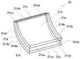
- FIG. 2 is a perspective view of the permanent magnet 21 according to the first embodiment of the present invention.
- Each of the plurality of permanent magnets 21 has a shape like a curved flat plate as shown in FIG. 2, and is a so-called segment type magnet having a substantially annular sector cross section in the bending direction, which is a flat plate. It is magnetized in one direction in the thickness direction.
- the annular fan shape is a part of the annular region (also referred to as annulus) surrounded by two concentric circles, which is sandwiched between two straight lines extending in the radial direction of the two concentric circles. It is a shape. Therefore, each of the plurality of permanent magnets 21 has a curved concave surface 21a, a curved convex surface 21b, two rectangular surfaces 21c, and two annular fan-shaped surfaces 21d.
- the curved concave surface 21a is a concave surface of the two curved surfaces of the permanent magnet 21.
- the curved convex surface 21b is a convex surface of the two curved surfaces of the permanent magnet 21.
- each of the plurality of permanent magnets 21 is magnetized in one direction in the thickness direction of the flat plate. Therefore, the curved concave surface 21a is the magnetic pole surface of either the S pole or the N pole, and the curved convex surface 21b is the magnetic pole surface of the opposite pole of the curved concave surface 21a.
- the two rectangular surfaces 21c and the two annular fan-shaped surfaces 21d are non-magnetic pole surfaces.
- Each of the two rectangular surfaces 21c is a rectangular plane located at the end of the permanent magnet 21 in the circumferential direction, and has a first groove 21cc.
- the first groove 21cc is a groove through which a refrigerant can flow, and the cross-sectional shape of the first groove 21cc is a semicircular shape.
- Each of the two rectangular surfaces 21c includes a first line of intersection 21ca that intersects the curved concave surface 21a and a second line of intersection 21cc that intersects the curved convex surface 21b.
- the first groove 21cc is provided between the first line of intersection 21ca and the second line of intersection 21cc, and extends along each of the first line of intersection 21ca and the second line of intersection 21cc.
- Each of the two annular fan-shaped surfaces 21d is an annular fan-shaped plane located at the axial end of the permanent magnet 21 and includes a second groove 21dc.
- the second groove 21dc is also a groove through which the refrigerant can flow, and the cross-sectional shape of the second groove 21dc is semicircular as in the cross-sectional shape of the first groove 21cc.
- Each of the two annular fan-shaped surfaces 21d includes a first line of intersection 21da that intersects the curved concave surface 21a and a second line of intersection 21db that intersects the curved convex surface 21b.
- the second groove 21dc is provided between the first line of intersection 21da and the second line of intersection 21db, and extends along each of the first line of intersection 21da and the second line of intersection 21db.
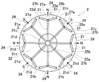
- FIG. 3 is a cross-sectional view of the rotor 2 and the shaft 3 along the AA'line of FIG.
- Each of the plurality of permanent magnets 21 is embedded in the axial direction of the rotor core 22 and is arranged in the circumferential direction of the rotor core 22 as shown in FIG.
- Permanent magnets 21 having the same polarity (N pole, S pole) of the curved concave surface 21a are arranged so as to be adjacent to each other on one side in the circumferential direction of the rotor core 22, thereby axially on the outer peripheral surface of the rotor 2.
- a plurality of magnetic poles 24 extending to the surface are formed.
- the plurality of magnetic poles 24 are provided at equal intervals in the circumferential direction of the rotor core 22, and the polarities of the two adjacent magnetic poles 24 in the circumferential direction of the rotor core 22 are different.
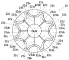
- FIG. 4 is a cross-sectional view of the rotor core 22 along the AA'line of FIG.
- the rotor core 22 is a cylindrical iron core in which steel plates are laminated.
- the rotor core 22 includes a shaft hole 22a, a plurality of first magnet insertion holes 22b, a plurality of second magnet insertion holes 22c, and a plurality of refrigerant flow holes 22d. ..
- the shaft hole 22a is a through hole provided in the central axis of the rotor core 22. As shown in FIGS. 1 and 3, the shaft 3 is inserted into the shaft hole 22a, and the rotor core 22 is coupled to the shaft 3 by a tight fit such as press fitting or shrink fitting.
- Each of the plurality of first magnet insertion holes 22b and each of the plurality of second magnet insertion holes 22c are holes that penetrate the rotor core 22 in the axial direction of the rotor core 22 and alternate in the circumferential direction of the rotor core 22. Is located in.
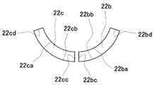
- FIG. 5 is an enlarged view of the adjacent first magnet insertion hole 22b and the second magnet insertion hole 22c according to the first embodiment of the present invention as viewed from the axial direction of the rotor core.
- a permanent magnet 21 having the same polarity as the curved concave surface 21a was inserted into each of the first magnet insertion hole 22b and the second magnet insertion hole 22c, and was applied to at least one of the curved concave surface 21a and the curved convex surface 21b of the permanent magnet 21. It is fixed with a foam adhesive.
- the first magnet insertion hole 22b has two rectangular surfaces, a first inner side surface 22ba facing the curved concave surface 21a of the permanent magnet 21, a second inner side surface 22bb facing the curved convex surface 21b of the permanent magnet 21, and a permanent magnet 21.
- a third inner side surface 22bc located on the inner diameter side of the rotor core 22 and a fourth inner side surface 22bd located on the outer diameter side of the rotor core 22 are provided.
- the second magnet insertion hole 22c has two, a first inner side surface 22ca facing the curved concave surface 21a of the permanent magnet 21, a second inner side surface 22cc facing the curved convex surface 21b of the permanent magnet 21, and a permanent magnet 21.
- the third inner side surface 22cc located on the inner diameter side of the rotor core 22 and the fourth inner side surface 22cd located on the outer diameter side of the rotor core 22 are provided. ..
- each of the plurality of first magnet insertion holes 22b and each of the plurality of second magnet insertion holes 22c has a curved concave surface 21a of each of the plurality of permanent magnets 21 outside the rotor core 22.
- the first inner side surfaces 22ba and 22ca are arranged on the outer diameter side of the rotor core 22 so as to be arranged on the diameter side.
- the first magnet insertion hole 22b and the second magnet insertion hole 22c are inserted so that the permanent magnets 21 adjacent to each other in the circumferential direction of the rotor core 22 and having the same polarity are inserted to form the magnetic pole 24.
- the first inner side surfaces 22ba and 22ca of the first magnet insertion hole 22b and the second magnet insertion hole 22c to be formed intersect each other on the outer diameter side of the rotor core 22.
- the rotary electric machine 10 can increase the magnetic anisotropy of the plurality of magnetic poles 24 formed on the outer peripheral surface of the rotor 2, and can increase the reluctance torque.
- each of the plurality of refrigerant flow holes 22d is a hole provided on the inner surface of the shaft hole 22a of the rotor core 22, and is a shaft hole 22a, a first magnet insertion hole 22b, and a second magnet insertion hole. Communicate with 22c.
- each of the plurality of refrigerant flow holes 22d extends from the inner side surface of the shaft hole 22a of the rotor core 22 in the radial direction of the rotor core 22 to form the magnetic pole 24, and the first magnet insertion hole 22b and the first. 2 Openings 22db and 22dc are formed in the third inner side surfaces 22bc and 22cc of the magnet insertion hole 22c, respectively.
- the first magnet insertion hole 22b and the second magnet insertion hole 22c communicate with each other through these openings 22db and 22dc and the refrigerant flow hole 22d.
- the two end rings 23 are two disks covering both ends of the rotor core 22, and are on the side (hereinafter referred to as the inflow side) in which the refrigerant inflow hole 3a described later is provided in the axial direction of the shaft 3.
- the end ring 23 is referred to as an inflow side end ring 231 and the end ring 23 on the opposite side (hereinafter referred to as an anti-inflow side) is referred to as an anti-inflow side end ring 232.
- the outer diameter of the inflow side end ring 231 is the outer diameter of each rotor core 22 of the inflow side second circumferential flow path 25d and the inflow side fourth circumferential flow path 27d (see FIGS. 3 and 7), which will be described later.
- the distance between the end and the center of the rotor core 22 is at least smaller than that of the first groove cc and the rotor core 22 of the inflow side second axial flow path 25b and the inflow side fourth axial flow path 27b, which will be described later. It is equal to the shortest distance in the radial direction of the central rotor core 22.
- the outer diameter of the anti-inflow side end ring 232 is the outer diameter of the rotor core 22 of each of the anti-inflow side second circumferential flow path 26d and the anti-inflow side fourth circumferential flow path 28d, which will be described later. At least smaller than the distance of the center of the rotor core 22, preferably, the first groove cc of the anti-inflow side second axial flow path 26b and the anti-inflow side fourth axial flow path 28b and the rotor core 22 described later. It is equal to the shortest distance in the radial direction of the central rotor core 22.
- each of the inflow side end ring 231 and the anti-inflow side end ring 232 is provided with a shaft hole 23a.
- the shaft hole 23a is a through hole provided at the center of each of the inflow side end ring 231 and the anti-inflow side end ring 232.
- the inner diameter of the shaft hole 23a is larger than the outer diameter of the shaft 3. The shaft 3 is inserted into the shaft hole 23a as shown in FIG.
- FIG. 6 is a cross-sectional view of the shaft along the AA'line of FIG.
- the shaft 3 is a rotating shaft, which is rotatably supported by two bearings 4 as shown in FIG. 1 and rotates together with a rotor core 22 to be coupled.
- the shaft 3 is provided with a refrigerant inflow hole 3a and a plurality of refrigerant flow holes 3b.
- the refrigerant inflow hole 3a is a hole provided along the central axis at the center of one end surface of the shaft 3 and communicates with each of the plurality of refrigerant flow holes 3b.
- Each of the plurality of refrigerant flow holes 3b is a hole extending from the inner peripheral surface of the refrigerant inflow hole 3a in the outer diameter direction of the shaft 3 and penetrating the outer peripheral surface of the shaft 3.
- Each of the plurality of openings 3c formed on the outer peripheral surface of the shaft 3 by each of the plurality of refrigerant flow holes 3b was formed on the inner surface of the shaft hole 22a by each of the plurality of refrigerant flow holes 22d of the rotor core 22. It overlaps with a plurality of openings 22da (see FIG. 4).
- each of the plurality of refrigerant flow holes 3b of the shaft 3 communicates with each of the plurality of refrigerant flow holes 22d of the rotor core 22.
- Each of the two bearings 4 is a radial ball bearing as shown in FIG. 1 and is fixed to each of the two end brackets 5.
- the bearing 4 is not limited to the radial ball bearing, and may be, for example, a radial roller bearing.
- the two end brackets 5 are disk-shaped parts that are attached to the ends of the housing 6 and close the opening of the housing 6.
- the housing 6 is a rigid body of a cylinder that covers and fixes the stator 1. On the side surface of the housing 6, one or more (two in FIG. 1) refrigerant discharge holes 6a penetrating the side surface of the housing 6 are provided. As shown in FIG. 1, one or more refrigerant discharge holes 6a are arranged in the lower part of the installed rotary electric machine 10.
- the rotary electric machine 10 configured in this way becomes an electric motor that outputs torque from the shaft 3 when power is supplied to the stator 1, and power is supplied from the stator 1 when rotational power is input to the shaft 3. It becomes a generator that outputs.
- the cooling system 100 is a cooling system that cools the permanent magnet 21 and suppresses demagnetization of the permanent magnet 21, and is a cooling system that cools the refrigerant 101, the oil pump 102 that sends the refrigerant 101 toward the rotary electric machine 10, and the refrigerant 101. It is equipped with 103. Oil, particularly automatic oil (ATF), is used as the refrigerant 101.
- ATF automatic oil
- FIG. 7 is a perspective view showing the configuration of the flow path of the refrigerant 101 in one of the plurality of magnetic poles 24 of the rotor 2 according to the first embodiment of the present invention.
- the flow path shown in FIG. 7 will be described in detail with reference to FIGS. 2 and 5.
- the first permanent magnet 211 is inserted on the inflow side, and the second permanent magnet 212 is inserted on the anti-inflow side.
- Each of the two first grooves 21cc of the first permanent magnet 211 forms an inflow side first axial flow path 25a between the third inner side surfaces 22bc of the first magnet insertion hole 22b, and the first magnet insertion hole 22b.
- a second axial flow path 25b on the inflow side is formed between the fourth inner side surfaces 22b of the above.
- each of the two first grooves 21cc of the second permanent magnet 212 forms a counter-inflow side first axial flow path 26a between the third inner side surfaces 22bc of the first magnet insertion hole 22b, and the first magnet.
- a second axial flow path 26b on the anti-inflow side is formed between the fourth inner side surface 22b of the insertion hole 22b.
- each of the two second grooves 21dc of the first permanent magnet 211 has an inflow side first circumferential flow path 25c between the annular fan-shaped surfaces 21d of the second permanent magnet 212 facing the axial direction of the rotor core 22. It is formed, and the inflow side second circumferential flow path 25d is formed between the inflow side end ring 231 and the facing surface with the rotor core 22.
- each of the two second grooves 21dc of the second permanent magnet 212 is located between the annular fan-shaped surfaces 21d of the first permanent magnet 211 facing the axial direction of the rotor core 22 in the anti-inflow side first circumferential flow path 26c. Is formed, and a second circumferential flow path 26d on the anti-inflow side is formed between the end ring 232 on the anti-inflow side and the facing surface with the rotor core 22.
- the inflow side first circumferential flow path 25c and the anti-inflow side first circumferential flow path 26c face each other, and the inflow side first circumferential flow path 25c and the anti-inflow side first circumferential flow path flow.
- the road 26c is one flow path (first circumferential flow path 256).
- the third permanent magnet 213 is inserted on the inflow side
- the fourth permanent magnet 214 is inserted on the anti-inflow side.
- Each of the two first grooves 21cc of the third permanent magnet 213 forms an inflow side third axial flow path 27a between the third inner side surfaces 22cc of the second magnet insertion hole 22c, and the second magnet insertion hole 22c.
- a fourth axial flow path 27b on the inflow side is formed between the fourth inner side surfaces 22cd of the above.
- each of the two first grooves 21cc of the fourth permanent magnet 214 forms a counter-inflow side third axial flow path 28a between the third inner side surfaces 22cc of the second magnet insertion hole 22c, and the second magnet.
- An anti-inflow side fourth axial flow path 28b is formed between the fourth inner side surface 22cd of the insertion hole 22c.
- each of the two second grooves 21dc of the third permanent magnet 213 has an inflow side third circumferential flow path 27c between the annular fan-shaped surfaces 21d of the fourth permanent magnet 214 facing in the axial direction of the rotor core 22. It is formed, and the inflow side fourth circumferential flow path 27d is formed between the inflow side end ring 231 and the facing surface with the rotor core 22.
- each of the two second grooves 21dc of the fourth permanent magnet 214 is located between the annular fan-shaped surfaces 21d of the third permanent magnet 213 facing the axial direction of the rotor core 22 and the counterflow side third circumferential flow path 28c. Is formed, and the anti-inflow side fourth circumferential flow path 28d is formed between the anti-inflow side end ring 232 and the facing surface with the rotor core 22.
- the inflow side third circumferential flow path 27c and the anti-inflow side third circumferential flow path 28c face each other, and the inflow side third circumferential flow path
- the 27c and the third circumferential flow path 28c on the anti-inflow side form one flow path (third circumferential flow path 278).
- the refrigerant 101 sent out from the oil pump 102 of the cooling system 100 and cooled by the oil cooler 103 is supplied to the refrigerant inflow hole 3a provided in the shaft 3 of the rotary electric machine 10.
- the refrigerant 101 supplied to the refrigerant inflow hole 3a is sent from the refrigerant inflow hole 3a to each of the plurality of refrigerant flow holes 3b.
- the refrigerant 101 sent to each of the refrigerant flow holes 3b flows through each of the refrigerant flow holes 3b, and from each of the plurality of openings 3c formed on the outer peripheral surface of the shaft 3, the shaft hole 22a of the rotor core 22 It is sent to each of the plurality of openings 22da (see FIGS. 4 and 7) formed on the inner surface.
- the refrigerant 101 sent to each of the plurality of openings 22da circulates through each of the plurality of refrigerant flow holes 22d of the rotor core 22, and the first magnet insertion hole 22b and the second magnet. It is sent to each of the openings 22db and 22dc formed in each of the third inner side surfaces 22bc and 22cc of the insertion hole 22c.
- the refrigerant 101 sent to the opening 22db is sent to the inflow side first axial flow path 25a, the anti-inflow side first axial flow path 26a, and the first circumferential flow path 256 communicating with the opening 22db.
- the refrigerant 101 sent to the inflow side first axial flow path 25a is sent to the inflow side second circumferential flow path 25d while cooling the first groove 21cc of the first permanent magnet 211.
- the refrigerant 101 sent to the inflow side second circumferential flow path 25d cools the second groove 21dc of the first permanent magnet 211 and is discharged from the discharge port 25e toward the coil 12.
- the refrigerant 101 sent to the anti-inflow side first axial flow path 26a is sent to the anti-inflow side second circumferential flow path 26d while cooling the first groove 21cc of the second permanent magnet 212.
- the refrigerant 101 sent to the second circumferential flow path 26d on the anti-inflow side cools the second groove 21 dc of the second permanent magnet 212 and is discharged from the discharge port 26e toward the coil 12.
- the refrigerant 101 sent to the first circumferential flow path 256 cools each of the first groove 21cc of the first permanent magnet 211 and the second permanent magnet 212, and counterflows with the inflow side second axial direction flow path 25b. It is sent to the side second axial flow path 26b.
- the refrigerant 101 sent to the inflow side second axial flow path 25b cools the first groove 21cc of the first permanent magnet 211 and is discharged from the discharge port 25e toward the coil 12.
- the refrigerant 101 sent to the second axial flow path 26b on the non-inflow side cools the first groove 21cc of the second permanent magnet 212 and is discharged from the discharge port 26e toward the coil 12.
- the refrigerant 101 sent to the opening 22dc is sent to the inflow side third axial flow path 27a, the anti-inflow side third axial flow path 28a, and the third circumferential flow path 278 communicating with the opening 22dc.
- the refrigerant 101 sent to the inflow side third axial flow path 27a is sent to the inflow side fourth circumferential flow path 27d while cooling the first groove 21cc of the third permanent magnet 213.
- the refrigerant 101 sent to the inflow side fourth circumferential flow path 27d cools the second groove 21dc of the third permanent magnet 213 and is discharged from the discharge port 27e toward the coil 12.
- the refrigerant 101 sent to the third axial flow path 28a on the anti-inflow side is sent to the fourth circumferential flow path 28d on the anti-inflow side while cooling the first groove 21cc of the fourth permanent magnet 214.
- the refrigerant 101 sent to the non-inflow side fourth circumferential flow path 28d cools the second groove 21dc of the fourth permanent magnet 214 and is discharged from the discharge port 28e toward the coil 12.
- the refrigerant 101 sent to the third circumferential flow path 278 cools each of the first groove 21cc of the third permanent magnet 213 and the fourth permanent magnet 214, and counterflows with the inflow side fourth axial flow path 27b. It is sent to the side fourth axial flow path 28b.
- the refrigerant 101 sent to the inflow side fourth axial flow path 27b cools the first groove 21cc of the third permanent magnet 213 and is discharged from the discharge port 27e toward the coil 12.
- the refrigerant 101 sent to the non-inflow side fourth axial flow path 28b cools the first groove 21cc of the fourth permanent magnet 214 and is discharged from the discharge port 28e toward the coil 12.
- the refrigerant 101 discharged from each of the discharge ports 25e to 28e toward the coil 12 is discharged to the outside of the rotary electric machine 10 from one or more refrigerant discharge holes 6a of the housing 6 after cooling the coil 12, and is a cooling system. It circulates 100 and is supplied again to the refrigerant inflow hole 3a provided in the shaft 3 of the rotary electric machine 10.
- the inflow side first circumferential flow path 25c and the anti-inflow side first circumferential flow path 26c face each other, and the inflow side first circumferential flow path 25c and the anti-inflow side first circumferential flow path flow.
- the path 26c becomes one flow path (first circumferential flow path 256), and the inflow side third circumferential flow path 27c and the anti-inflow side third circumferential flow path 28c face each other, and the inflow side third circumferential direction.
- the flow path 27c and the counter-inflow side third circumferential flow path 28c form one flow path (third circumferential flow path 278).
- one of the annular fan-shaped surfaces 21d of the two permanent magnets 21 adjacent to each other in the axial direction of the rotor core 22 may include the second groove 21dc.
- the rotary electric machine 10 of the first embodiment described above has a rotor core 22 having magnet insertion holes (first magnet insertion hole 22b and second magnet insertion hole 22c) and a magnet insertion hole (first magnet insertion hole 22b and second magnet insertion hole 22c).
- the permanent magnet 21 inserted into the two magnet insertion holes 22c) is provided in at least one of the plurality of non-magnetic pole surfaces (two rectangular surfaces 21c and two annular fan-shaped surfaces 21d) of the permanent magnet 21, and the refrigerant 101 flows through. It is provided with possible grooves (first groove 21cc and second groove 21dc). Therefore, the permanent magnet 21 can be cooled by flowing the refrigerant 101 through this groove, and demagnetization due to the high temperature of the permanent magnet 21 can be suppressed.
- FIG. 9 is a cross-sectional analysis diagram showing the ease of demagnetization by analyzing the easily demagnetized portion of the rotor 200 according to the comparative example by a computer.
- the ease of demagnetization increases in the order of blue ⁇ yellow ⁇ red.
- the non-magnetic pole surface 201c is not provided with a groove.
- the permanent magnet 201 in the rotor 200 according to this comparative example is red in the central portion of the cross section of the non-magnetic pole surface 201c, and is easily demagnetized.
- the permanent magnet 21 of the rotary electric machine 10 of the present embodiment has a groove through which the refrigerant 101 can flow in at least one of a plurality of non-magnetic pole surfaces (two rectangular surfaces 21c and two annular fan-shaped surfaces 21d) of the permanent magnet 21. (1st groove 21cc and 2nd groove 21dc) are provided. That is, as shown in FIG.
- a groove (first groove 21cc and second groove 21dc) is provided in the center of the cross section of the non-magnetic pole surface analyzed to be easily demagnetized by the permanent magnet 201 according to the comparative example.
- Demagnetization due to the shape of the permanent magnet 21 can be suppressed.
- demagnetization due to heat generation can be suppressed without reducing the volume of the permanent magnet 21 (executive magnet volume) that contributes to the torque that is not demagnetized.
- leakage flux is likely to occur at the bridge 202 of the rotor core in contact with the non-magnetic pole surface 201c of the permanent magnet 201.
- the rotor 2 of the present embodiment has a groove (first groove 21cc and second groove 21cc) in at least one of a plurality of non-magnetic pole surfaces (two rectangular surfaces 21c and two annular fan-shaped surfaces 21d) which are ends of the permanent magnet 21.
- a groove 21 dc) is provided, and a gap is provided between the plurality of non-magnetic pole surfaces and the rotor core 22. The generation of leakage flux can be suppressed by this void.
- the groove (first groove 21cc) through which the refrigerant 101 can flow is the first magnet insertion hole 22b and the second magnet insertion among the plurality of non-magnetic pole surfaces of the permanent magnet 21. It is provided on at least one of the non-magnetic pole surfaces (two rectangular surfaces 21c) facing the inner side surface (third inner side surface 22bc, 22cc and fourth inner side surface 22bd, cd) of the hole 22c.
- the flow path formed by the first groove 21cc of the permanent magnet 21 and the third inner side surfaces 22bc and 22cc inflow side first axial flow path 25a and anti-inflow side first axial flow path shown in FIG. 7).
- the inflow side 4th axial direction flow path 27b and the anti-inflow side 4th axial direction flow path 28b) can efficiently cool the temperature rise due to the harmonics generated on the outer diameter side of the rotor 2, and the temperature of the permanent magnet 21 is increased. It is possible to suppress demagnetization due to.
- a plurality of permanent magnets 21 are inserted into the magnet insertion holes (first magnet insertion hole 22b and second magnet insertion hole 22c) and arranged in the axial direction of the rotor core 22.
- the magnet 21 and the flowable groove face each other in two adjacent permanent magnets 21 of the plurality of permanent magnets 21 among the plurality of non-magnetic pole surfaces (two rectangular surfaces 21c and two annular fan-shaped surfaces 21d). It is provided on at least one of the non-magnetic pole surfaces (two annular fan-shaped surfaces 21d).
- the non-magnetic pole surfaces (two annular fan-shaped surfaces 21d) facing each other in the two adjacent permanent magnets 21 in the plurality of permanent magnets 21 are arranged inside the rotor 2, and heat is more likely to be trapped than the outside of the rotor 2. However, with the above configuration, it can be cooled by the refrigerant 101.
- FIG. 10 is a perspective view showing the configuration of the flow path of the refrigerant 101 in one of the plurality of magnetic poles 24 of the rotor 2 according to the second embodiment of the present invention.
- the difference between the rotor 2 according to the present embodiment and the first embodiment is that the rotor 2 is inserted into the first rotor core 221 and the second rotor core 222 and the second magnet insertion hole 22c inserted in the first magnet insertion hole 22b.
- Each of the third rotor core 223 and the fourth rotor core 224 is divided in the axial direction of the rotor core 22. That is, in the first embodiment, two permanent magnets 21 are inserted in each of the first magnet insertion hole 22b and the second magnet insertion hole 22c in the axial direction of the rotor core 22. On the other hand, in the rotor 2 of the present embodiment, four permanent magnets 21 are inserted in each of the first magnet insertion hole 22b and the second magnet insertion hole 22c in the axial direction of the rotor core 22.
- the flow path of the refrigerant 101 of the present embodiment is, in addition to the flow path of the refrigerant 101 of the first embodiment, the first circumferential flow path 256 and the inflow side second circumference in the axial direction of the rotor core 22.
- the refrigerant flow hole 22d is provided between the first circumferential flow path 256 and the third circumferential flow path 278.
- the present invention is not limited to this embodiment, and is not limited to this embodiment, but is between the inflow side fifth circumferential flow path 25f and the inflow side sixth circumferential flow path 27f, and between the anti-inflow side fifth circumferential flow path 26f and the anti-inflow side sixth.
- a refrigerant flow hole 22d may be provided between the circumferential flow path 28f and the flow path 28f.
- the present invention is not limited to this embodiment, and a number of permanent magnets 21 different from those in the above embodiment are inserted in each of the first magnet insertion hole 22b and the second magnet insertion hole 22c in the axial direction of the rotor core 22. May be good.
- the rotor 2 In addition to the flow path of the refrigerant 101 of the first embodiment, the rotor 2 according to the present embodiment has an inflow side fifth circumferential flow path 25f, an anti-inflow side fifth circumferential flow path 26f, and an inflow side sixth circumference. A directional flow path 27f and a non-inflow side sixth circumferential direction flow path 28f are provided. Therefore, the cooling performance of the permanent magnet 21 can be improved as compared with the rotor 2 according to the first embodiment, and the occurrence of demagnetization of the permanent magnet 21 can be suppressed.
- FIG. 11 is a cross-sectional view taken along the line AA'of FIG. 1 of the rotor 2 according to the third embodiment of the present invention.
- the difference between the rotor 2 according to the present embodiment and the first embodiment is that the plurality of permanent magnets 21, the plurality of first magnet insertion holes 22b, and the plurality of second magnet insertion holes 22c are perpendicular to the axis of the rotor core 22. It is a cross-sectional shape in the direction.
- each of the plurality of permanent magnets 21 is a so-called segment type magnet, and the cross-sectional shape in the direction perpendicular to the axis of the rotor core 22 is a substantially annular sector.
- each of the plurality of permanent magnets 21 of the present embodiment is a so-called square magnet, and the cross-sectional shape in the direction perpendicular to the axis of the rotor core 22 is substantially rectangular, and corresponds to the curved concave surface 21a of the first embodiment.
- each of the plurality of first magnet insertion holes 22b and each of the plurality of second magnet insertion holes 22c has a substantially annular fan shape in the cross-sectional shape in the direction perpendicular to the axis of the rotor core 22. It is a through hole of.
- each of the plurality of first magnet insertion holes 22b and each of the plurality of second magnet insertion holes 22c of the present embodiment are through holes having a rectangular cross-sectional shape in the direction perpendicular to the axis of the rotor core 22.
- first inner side surface 22ba and the second inner side surface 22ba of the first magnet insertion hole 22b and the first inner side surface 22ca and the second inner side surface 22cc of the second magnet insertion hole 22c which were curved surfaces in the first embodiment, Is a flat surface in this embodiment.
- the permanent magnet 21 according to the present embodiment is a flat plate magnet and has the same shape of the magnetic pole surface, all the magnetic poles 24 can be formed by one type of permanent magnet 21 unlike the first embodiment. Therefore, the manufacturing cost can be suppressed as compared with the rotor 2 according to the first embodiment.
- FIG. 12 is a perspective view showing the shape of the end faces of the permanent magnets 21 adjacent to each other in the axial direction of the rotor 2 according to the fourth embodiment of the present invention.
- the permanent magnet 21 according to the present embodiment is different from the second embodiment in that each of the facing non-magnetic pole surfaces 21dd of the two adjacent permanent magnets 21 among the plurality of permanent magnets 21 is in the axial direction of the rotor core 22.
- a point is that a protruding surface 21de is provided on the protruding surface 21de, and a second groove 21dc is provided on the protruding surface 21de.
- each of the opposite non-magnetic pole surfaces 21d of the two adjacent permanent magnets 21 is rectangular from the rectangular surface 21dd and the rectangular surface 21dd. It is provided with a protruding surface 21de protruding in the normal direction of the surface 21dd. A second groove 21 dc is provided on the protruding surface 21 de.
- the non-magnetic pole surfaces 21d of the first permanent magnet 211 and the second permanent magnet 212 inserted into the magnet insertion holes are the protruding surfaces 21de of the first permanent magnet 211 and the second permanent magnet 212.
- the rectangular surface 21dd is in contact with the rectangular surface 21dd, and the rectangular surface 21dd of the first permanent magnet 211 and the protruding surface 21de of the second permanent magnet 212 are held in contact with each other.
- the circumferential flow path 21df is formed by the second groove 21dc provided on each protruding surface 21de.
- the permanent magnet 21 is an example of the flat plate magnet of the second embodiment, but the segment type magnet of the first embodiment may be used.
- FIG. 13 is a cross-sectional view of a groove provided on the non-magnetic pole surface of the permanent magnet 21 according to the fifth embodiment of the present invention.
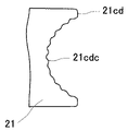
- the differences between the permanent magnet 21 according to the present embodiment and the first embodiment are as follows. That is, in the first embodiment, the surfaces of the grooves (first groove 21cc and second groove 21dc) provided in the non-magnetic pole surfaces (two rectangular surfaces 21c and two annular fan-shaped surfaces 21d) of the permanent magnet 21 become smooth. There is. On the other hand, in the present embodiment, as shown in FIG. 13, the surface of the groove 21cdc provided in the non-magnetic pole surface 21cd of the permanent magnet 21 is provided with irregularities.
- the groove on the non-magnetic pole surface of the permanent magnet 21 of the present embodiment has an uneven surface, and the surface area of the groove is smoother than that of the permanent magnet 21 of the first embodiment, and the cooling performance can be improved. ..
- FIG. 14 is a cross-sectional view of a groove provided on the non-magnetic pole surface of the permanent magnet 21 according to the sixth embodiment of the present invention.
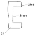
- the differences between the permanent magnet 21 according to the present embodiment and the first embodiment are as follows. That is, in the first embodiment, the cross section of the grooves (first groove 21cc and second groove 21dc) provided in the non-magnetic pole surfaces (two rectangular surfaces 21c and two annular fan-shaped surfaces 21d) of the permanent magnet 21 is semicircular. It has become. On the other hand, in the present embodiment, as shown in FIG. 14, the cross section of the groove 21cdc provided in the non-magnetic pole surface 21cd of the permanent magnet 21 is rectangular.
- the groove on the non-magnetic pole surface of the permanent magnet 21 of the present embodiment has a rectangular cross section, it can be formed by, for example, cutting, and the manufacturing cost can be suppressed.
- FIG. 15 is a schematic view showing a magnetic pole 24 according to a seventh embodiment of the present invention.
- the points that the magnetic pole 24 according to this embodiment is different from that of the first embodiment are as follows. That is, in the first embodiment, the magnetic pole 24 is formed by two permanent magnets 21 adjacent to each other in the circumferential direction of the rotor 2. On the other hand, in the first embodiment, the magnetic pole 24 is formed by a plurality of (three in FIG. 15) permanent magnets 21 adjacent to each other in the circumferential direction of the rotor 2.
- the permanent magnets 21 are a plurality of (three in FIG. 15) permanent magnets 21 forming one magnetic pole 24, and each of the plurality of permanent magnets 21 is an individual magnet. Inserted into the insertion holes 22b, 22c, 22e, the grooves (first groove 21cc, second groove 21dc) of the permanent magnet 21 are non-magnetic pole surfaces (rectangular) facing each other in two adjacent permanent magnets 21 of the plurality of permanent magnets 21. It is provided on at least one (both in this embodiment) of the surface 21c and the annular fan-shaped surface 21d).
- Each of the plurality of permanent magnets 21 forming the magnetic pole 24 of the present embodiment is provided with a groove on at least one of the non-magnetic pole surfaces facing each other in the two adjacent permanent magnets 21. Therefore, the magnetic pole 24 is formed by arranging three or more permanent magnets 21 in the circumferential direction of the rotor 2, and even the permanent magnet 21e sandwiched between the permanent magnets 21 in the circumferential direction of the rotor 2 has a groove on the non-magnetic pole surface. ..
- the arrangement of the permanent magnets 21 on the magnetic pole 24 is different from that of the first embodiment and the second embodiment, and even when the permanent magnets 21e are provided with the permanent magnets 21 sandwiching both sides of the rotor 2 in the circumferential direction. Since the permanent magnet 21e is provided with a groove through which the refrigerant 101 can flow on the non-magnetic pole surface, it is possible to suppress heat generation and demagnetization due to the shape without reducing the effective magnet volume.
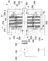
- FIG. 16 is a front surface in which the end ring according to the eighth embodiment of the present invention is attached to the end surface of the rotor core
- FIG. 17 shows a schematic configuration of the rotary electric machine 10 according to the eighth embodiment of the present invention. It is sectional drawing which shows.
- the outer diameter of the end ring 23 (inflow side end ring 231 and anti-inflow side end ring 232) of the first embodiment is the flow path on the outer diameter side of the rotor 2 (inflow side second circumferential flow path 25d).
- the outer diameter of the end ring 23 of the present embodiment is at least larger than the distance between the outer end in the radial direction of the rotor core 22 and the center of the rotor core 22 in the flow path on the outer diameter side of the rotor 2.
- the end ring 23 is provided with a plurality of refrigerant discharge holes 23b.
- Each of the plurality of refrigerant discharge holes 23b has a plurality of first magnet insertion holes 22b of the rotor core 22 and a plurality of them when each of the two end rings 23 is attached and fixed to each of the end faces of the rotor core 22. It communicates with the second groove 21dc of the permanent magnet 21 inserted into each of the second magnet insertion holes 22c. Therefore, the inner diameter value and the center position of each of the plurality of refrigerant discharge holes 23b are determined based on the positions and widths of the first groove 21cc and the second groove 21dc.
- each of the two end rings 23 is attached and fixed to each of the end faces of the rotor core 22, it is inserted into each of the plurality of first magnet insertion holes 22b and the plurality of second magnet insertion holes 22c of the rotor core 22. It is preferable to position the center of each of the plurality of refrigerant discharge holes 23b at the center of the center line of the second groove 21dc of the inserted permanent magnet 21.
- the refrigerant 101 that has passed through each flow path of the rotor 2 is discharged from the discharge ports 25e to 28e toward the coil 12.
- the refrigerant 101 that has passed through each flow path of the rotor 2 is discharged from each of the plurality of refrigerant discharge holes 23b toward the coil 12.
- the end ring 23 of the present embodiment has a plurality of rotor cores 22 when each of the plurality of refrigerant discharge holes 23b attaches and fixes each of the two end rings 23 to each of the end faces of the rotor core 22. It communicates with the second groove 21dc of the permanent magnet 21 inserted into each of the first magnet insertion hole 22b and the plurality of second magnet insertion holes 22c. As a result, the refrigerant 101 that has passed through each flow path of the rotor 2 is discharged from each of the plurality of refrigerant discharge holes 23b.
- the present embodiment can discharge the refrigerant 101 at a position separated from the end face of the rotor core 22 by the thickness of the end ring 23, and is between the rotor 2 and the stator 1. It is possible to prevent the refrigerant 101 from entering the voids.
- each of the two end rings 23 is attached and fixed to each of the end faces of the rotor core 22 and the end ring 23 is viewed from the axial direction of the rotor 2, it rotates with each of the plurality of refrigerant discharge holes 23b.
- a plurality of flow paths extending in the axial direction on the outer diameter side of the child 2 (rotor 2 inflow side second axial flow path 25b, anti-inflow side second axial flow path 26b, and inflow side fourth axial flow path 27b).
- each of the anti-inflow side fourth axial flow path 28b) are preferably not overlapped with each other.
- each of the plurality of flow paths extending in the axial direction on the outer diameter side of the rotor 2 is oriented in the axial direction of the rotor 2. It is preferable that the ejected refrigerant 101 abuts on the facing surface of each of the two end rings 23 with the rotor core 22. As a result, the cooling material 101 flowing through each of the plurality of flow paths extending in the axial direction on the outer diameter side of the rotor 2 and ejecting in the axial direction of the rotor 2 is directly transmitted from each of the plurality of refrigerant discharge holes 23b to the rotor 2. It is suppressed that the coil 12 is discharged to the outside of the rotary electric machine 10 without being cooled, and the coil 12 can be efficiently cooled (see FIG. 17).
- the present invention is not limited to the above-described embodiment, and includes various modifications.
- the above-described embodiment has been described in detail in order to explain the present invention in an easy-to-understand manner, and is not necessarily limited to the one including all the described configurations.
- it is possible to replace a part of the configuration of one embodiment with the configuration of another embodiment and it is also possible to add the configuration of another embodiment to the configuration of one embodiment.
- the flow path of the refrigerant 101 may include a flow path formed by a groove (at least one of the first groove 21cc and the second groove 21dc) provided on the non-magnetic pole surface of the permanent magnet 21, and the like.
- the flow path of the above is not limited to the above-described embodiment.
- the embodiment of the present invention may have the following aspects.
- the example in which the magnetic pole 24 of the rotor 2 has 8 poles is shown, but other poles may be used.
Landscapes
- Engineering & Computer Science (AREA)
- Power Engineering (AREA)
- Iron Core Of Rotating Electric Machines (AREA)
- Permanent Field Magnets Of Synchronous Machinery (AREA)
Abstract
Description
図1は、本発明の第1の実施形態による回転電機10と冷却システム100の概略構成を示す断面図である。
上記の第1実施形態の回転電機10は、磁石挿入孔(第1磁石挿入孔22bと第2磁石挿入孔22c)を有する回転子鉄心22と、磁石挿入孔(第1磁石挿入孔22bと第2磁石挿入孔22c)に挿入された永久磁石21と、永久磁石21の複数の非磁極面(2つの矩形面21cと2つの環状扇形面21d)の少なくとも1つに設けられ、冷媒101が流通可能な溝(第1溝21ccと第2溝21dc)を備える。そのため、この溝に冷媒101を流すことにより永久磁石21を冷却でき、永久磁石21の高温化による減磁を抑制できる。
図10は、本発明の第2実施形態に係る回転子2の複数の磁極24の1つにおける冷媒101の流路の構成を示す斜視図である。
本実施形態に係る回転子2は、第1実施形態の冷媒101の流路に加えて、流入側第5周方向流路25fと反流入側第5周方向流路26fと流入側第6周方向流路27fと反流入側第6周方向流路28fとを備える。そのため、第1実施形態に係る回転子2より永久磁石21の冷却性能を向上でき、永久磁石21の減磁の発生を抑制できる。
図11は、本発明の第3実施形態に係る回転子2の図1のA-A‘線による断面図である。本実施形態に係る回転子2が第1実施形態と異なる点は、複数の永久磁石21と複数の第1磁石挿入孔22bと複数の第2磁石挿入孔22cの回転子鉄心22の軸に対する垂直方向の断面形状である。
本実施形態に係る永久磁石21は平板磁石で、磁極面の形状が同じため、第1実施形態と異なり一種類の永久磁石21ですべての磁極24を形成できる。そのため、第1実施形態に係る回転子2より製造コストを抑制できる。
図12は、本発明の第4実施形態に係る回転子2の軸方向に隣合う永久磁石21の端面の形状を示す斜視図である。本実施形態に係る永久磁石21が第2実施形態と異なる点は、複数の永久磁石21のうち隣合う2つの永久磁石21の対向する非磁極面21ddの各々が、回転子鉄心22の軸方向に突出する突出面21deを備え、第2溝21dcが突出面21deに設けられている点である。
本実施形態では、複数の永久磁石21のうち隣合う2つの永久磁石21が、対向する非磁極面21dが組み合い、位置決めの精度を向上させることができる。
図13は、本発明の第5実施形態に係る永久磁石21の非磁極面に備わる溝の断面図である。本実施形態に係る永久磁石21が第1実施形態と異なる点は以下の通りである。即ち、第1本実施形態では永久磁石21の非磁極面(2つの矩形面21cと2つの環状扇形面21d)に備わる溝(第1溝21ccと第2溝21dc)の表面が平滑となっている。一方、本実施形態では、図13に示すように永久磁石21の非磁極面21cdに備わる溝21cdcの表面に凸凹を備える。
本実施形態の永久磁石21の非磁極面の溝は、表面に凸凹を備え、溝の表面が平滑である第1本実施形態の永久磁石21より表面積が広く、冷却性能を向上させることができる。
図14は、本発明の第6実施形態に係る永久磁石21の非磁極面に備わる溝の断面図である。本実施形態に係る永久磁石21が第1実施形態と異なる点は以下の通りである。即ち、第1本実施形態では永久磁石21の非磁極面(2つの矩形面21cと2つの環状扇形面21d)に備わる溝(第1溝21ccと第2溝21dc)の断面が半円状となっている。一方、本実施形態では、図14に示すように永久磁石21の非磁極面21cdに備わる溝21cdcの断面が矩形となっている。
本実施形態の永久磁石21の非磁極面の溝は断面が矩形であるため、例えば、削りだしにより形成でき、製造コストを抑制できる。
図15は、本発明の第7実施形態に係る磁極24を示す概略図である。本実施形態に係る磁極24が第1実施形態と異なる点は、以下の通りである。即ち、第1実施形態では磁極24は、回転子2の周方向に隣合う2つの永久磁石21により形成されている。一方、第1実施形態では磁極24は、回転子2の周方向に隣合う複数(図15は3つ)の永久磁石21により形成されている。
本実施形態の磁極24を形成する複数の永久磁石21の各々は、隣合う2つの永久磁石21において対向する非磁極面の少なくとも一方に溝が設けられている。そのため、磁極24が回転子2の周方向に永久磁石21を3以上配列することにより形成され、回転子2の周方向に永久磁石21に挟まれた永久磁石21eでも非磁極面に溝を備える。
図16は、本発明の第8の実施形態に係るエンドリングを回転子鉄心の端面に取り付けた正面面であり、図17は、本発明の第8の実施形態による回転電機10の概略構成を示す断面図である。
本実施形態のエンドリング23は、複数の冷媒排出孔23bの各々が、2枚のエンドリング23の各々を回転子鉄心22の端面の各々に取り付け固定したときに、回転子鉄心22の複数の第1磁石挿入孔22bと複数の第2磁石挿入孔22cの各々に挿入された永久磁石21の第2溝21dcと連通する。これにより、回転子2の各流路を通過した冷媒101は、複数の冷媒排出孔23bの各々から吐出される。そのため、本実施形態は、第1実施形態と異なり、回転子鉄心22の端面からエンドリング23の厚さだけ離れた位置で冷媒101を排出することができ、回転子2と固定子1の間の空隙に冷媒101が入り込むことを抑制できる。
Claims (7)
- 磁石挿入孔を有する回転子鉄心と、
前記磁石挿入孔に挿入された永久磁石と、
前記永久磁石の複数の非磁極面の少なくとも1つに設けられ、冷媒が流通可能な溝とを備えることを特徴とする回転電機。 - 請求項1に記載の回転電機において、
前記溝が、前記複数の非磁極面のうちの、前記磁石挿入孔の内側面に対向する非磁極面の少なくとも1つに設けられていることを特徴とする回転電機。 - 請求項1に記載の回転電機において、
前記永久磁石は、前記磁石挿入孔に挿入され前記回転子鉄心の軸方向に配列された複数の永久磁石であり、
前記溝が、前記複数の非磁極面のうちの、前記複数の永久磁石の隣合う2つの永久磁石において対向する非磁極面の少なくとも一方に設けられていることを特徴とする回転電機。 - 請求項3に記載の回転電機において、
前記複数の永久磁石のうち隣合う2つの永久磁石の対向する非磁極面の各々は、前記回転子鉄心の軸方向に突出する突出面を備え、
前記溝が、前記突出面に設けられていることを特徴とする回転電機。 - 請求項1に記載の回転電機において、
前記溝は、表面に凸凹を備えることを特徴とする回転電機。 - 請求項1に記載の回転電機において、
前記永久磁石は、1つの磁極を形成する複数の永久磁石であり、
前記複数の永久磁石の各々は、個別の前記磁石挿入孔に挿入され、
前記溝は、前記複数の永久磁石の隣合う2つの永久磁石において対向する非磁極面の少なくとも一方に設けられていることを特徴とする回転電機。 - 請求項1に記載の回転電機において、
前記溝が、前記複数の非磁極面の全てに設けられていることを特徴とする回転電機。
Priority Applications (4)
| Application Number | Priority Date | Filing Date | Title |
|---|---|---|---|
| CN202180066327.7A CN116406492A (zh) | 2020-10-20 | 2021-08-31 | 旋转电机 |
| US18/247,770 US12512709B2 (en) | 2020-10-20 | 2021-08-31 | Rotating electric machine |
| DE112021004300.5T DE112021004300T5 (de) | 2020-10-20 | 2021-08-31 | Drehende elektrische maschine |
| JP2022557252A JP7411825B2 (ja) | 2020-10-20 | 2021-08-31 | 回転電機 |
Applications Claiming Priority (2)
| Application Number | Priority Date | Filing Date | Title |
|---|---|---|---|
| JP2020176188 | 2020-10-20 | ||
| JP2020-176188 | 2020-10-20 |
Publications (1)
| Publication Number | Publication Date |
|---|---|
| WO2022085306A1 true WO2022085306A1 (ja) | 2022-04-28 |
Family
ID=81291203
Family Applications (1)
| Application Number | Title | Priority Date | Filing Date |
|---|---|---|---|
| PCT/JP2021/031873 Ceased WO2022085306A1 (ja) | 2020-10-20 | 2021-08-31 | 回転電機 |
Country Status (5)
| Country | Link |
|---|---|
| US (1) | US12512709B2 (ja) |
| JP (1) | JP7411825B2 (ja) |
| CN (1) | CN116406492A (ja) |
| DE (1) | DE112021004300T5 (ja) |
| WO (1) | WO2022085306A1 (ja) |
Families Citing this family (2)
| Publication number | Priority date | Publication date | Assignee | Title |
|---|---|---|---|---|
| US20260155686A1 (en) * | 2021-11-08 | 2026-06-04 | Hitachi Astemo, Ltd. | Rotating electric machine |
| DE102024134981A1 (de) * | 2024-11-27 | 2026-05-28 | Magna powertrain gmbh & co kg | Elektrische Maschine mit Kühlölleitungen sowie Verfahren zur Herstellung eines Kühlmittelstroms |
Citations (2)
| Publication number | Priority date | Publication date | Assignee | Title |
|---|---|---|---|---|
| JP2003061282A (ja) * | 2001-08-10 | 2003-02-28 | Nissan Motor Co Ltd | 回転電機のロータ構造 |
| JP2006014399A (ja) * | 2004-06-22 | 2006-01-12 | Nissan Motor Co Ltd | アキシャルギャップ回転電機の冷却構造 |
Family Cites Families (5)
| Publication number | Priority date | Publication date | Assignee | Title |
|---|---|---|---|---|
| JP4380192B2 (ja) * | 2003-03-24 | 2009-12-09 | 株式会社安川電機 | リニアモータ用永久磁石配列体とこれを用いたリニアモータ |
| JP2015089178A (ja) * | 2013-10-29 | 2015-05-07 | 三菱電機株式会社 | 永久磁石埋込型回転電機 |
| US20190131837A1 (en) * | 2016-06-03 | 2019-05-02 | Aisin Aw Co., Ltd. | Rotor |
| JP2019058048A (ja) * | 2017-09-22 | 2019-04-11 | アイシン・エィ・ダブリュ株式会社 | 永久磁石及びそれを備えた回転電機 |
| JP7378369B2 (ja) * | 2020-09-09 | 2023-11-13 | 日立Astemo株式会社 | 回転電機の回転子、回転電機及び電動駆動装置 |
-
2021
- 2021-08-31 JP JP2022557252A patent/JP7411825B2/ja active Active
- 2021-08-31 WO PCT/JP2021/031873 patent/WO2022085306A1/ja not_active Ceased
- 2021-08-31 DE DE112021004300.5T patent/DE112021004300T5/de active Pending
- 2021-08-31 US US18/247,770 patent/US12512709B2/en active Active
- 2021-08-31 CN CN202180066327.7A patent/CN116406492A/zh active Pending
Patent Citations (2)
| Publication number | Priority date | Publication date | Assignee | Title |
|---|---|---|---|---|
| JP2003061282A (ja) * | 2001-08-10 | 2003-02-28 | Nissan Motor Co Ltd | 回転電機のロータ構造 |
| JP2006014399A (ja) * | 2004-06-22 | 2006-01-12 | Nissan Motor Co Ltd | アキシャルギャップ回転電機の冷却構造 |
Also Published As
| Publication number | Publication date |
|---|---|
| US12512709B2 (en) | 2025-12-30 |
| JPWO2022085306A1 (ja) | 2022-04-28 |
| DE112021004300T5 (de) | 2023-07-06 |
| JP7411825B2 (ja) | 2024-01-11 |
| CN116406492A (zh) | 2023-07-07 |
| US20230336040A1 (en) | 2023-10-19 |
Similar Documents
| Publication | Publication Date | Title |
|---|---|---|
| JP6815510B2 (ja) | 回転電機 | |
| CN103563219B (zh) | 旋转电机 | |
| CN105281456B (zh) | 旋转电机的转子 | |
| CN106257801B (zh) | 旋转电机的转子 | |
| US9013082B2 (en) | Rotating machine and rotor thereof | |
| JP6079733B2 (ja) | 回転電機のロータ | |
| CN103296808A (zh) | 用于旋转电机的转子的冷却结构以及旋转电机 | |
| JP4082359B2 (ja) | 回転電機の冷却構造 | |
| CN110247497B (zh) | 旋转电机的转子 | |
| JP2012235546A (ja) | ロータおよび回転電機 | |
| JP5120538B2 (ja) | モータの冷却構造 | |
| JP7142072B2 (ja) | 回転電機のロータ | |
| JP2021093879A (ja) | ロータ及び回転電機 | |
| JP2013183481A (ja) | 回転電機用ロータの冷却構造、および、回転電機 | |
| JP6230478B2 (ja) | 回転子、回転電機、および圧縮機 | |
| JP2009232535A (ja) | 回転電機の回転子 | |
| JP6402739B2 (ja) | 回転電機 | |
| JP7411825B2 (ja) | 回転電機 | |
| JP2006014399A (ja) | アキシャルギャップ回転電機の冷却構造 | |
| JP5772415B2 (ja) | 回転電機のロータ構造 | |
| JP5710886B2 (ja) | 回転電機 | |
| JP2013051805A (ja) | 回転電機の冷却構造 | |
| JP7318138B1 (ja) | 回転子および回転電機 | |
| JP6875350B2 (ja) | 回転電機 | |
| JP7603859B1 (ja) | ロータ構造 |
Legal Events
| Date | Code | Title | Description |
|---|---|---|---|
| 121 | Ep: the epo has been informed by wipo that ep was designated in this application |
Ref document number: 21882447 Country of ref document: EP Kind code of ref document: A1 |
|
| ENP | Entry into the national phase |
Ref document number: 2022557252 Country of ref document: JP Kind code of ref document: A |
|
| 122 | Ep: pct application non-entry in european phase |
Ref document number: 21882447 Country of ref document: EP Kind code of ref document: A1 |
|
| WWG | Wipo information: grant in national office |
Ref document number: 18247770 Country of ref document: US |