WO2022085199A1 - ガイディングカテーテル - Google Patents
ガイディングカテーテル Download PDFInfo
- Publication number
- WO2022085199A1 WO2022085199A1 PCT/JP2020/039980 JP2020039980W WO2022085199A1 WO 2022085199 A1 WO2022085199 A1 WO 2022085199A1 JP 2020039980 W JP2020039980 W JP 2020039980W WO 2022085199 A1 WO2022085199 A1 WO 2022085199A1
- Authority
- WO
- WIPO (PCT)
- Prior art keywords
- tip
- shaft
- lumen
- guiding catheter
- layer
- Prior art date
- Legal status (The legal status is an assumption and is not a legal conclusion. Google has not performed a legal analysis and makes no representation as to the accuracy of the status listed.)
- Ceased
Links
Images



Classifications
-
- A—HUMAN NECESSITIES
- A61—MEDICAL OR VETERINARY SCIENCE; HYGIENE
- A61M—DEVICES FOR INTRODUCING MEDIA INTO, OR ONTO, THE BODY; DEVICES FOR TRANSDUCING BODY MEDIA OR FOR TAKING MEDIA FROM THE BODY; DEVICES FOR PRODUCING OR ENDING SLEEP OR STUPOR
- A61M25/00—Catheters; Hollow probes
- A61M25/01—Introducing, guiding, advancing, emplacing or holding catheters
- A61M25/06—Body-piercing guide needles or the like
- A61M25/0662—Guide tubes
-
- A—HUMAN NECESSITIES
- A61—MEDICAL OR VETERINARY SCIENCE; HYGIENE
- A61M—DEVICES FOR INTRODUCING MEDIA INTO, OR ONTO, THE BODY; DEVICES FOR TRANSDUCING BODY MEDIA OR FOR TAKING MEDIA FROM THE BODY; DEVICES FOR PRODUCING OR ENDING SLEEP OR STUPOR
- A61M25/00—Catheters; Hollow probes
- A61M25/0021—Catheters; Hollow probes characterised by the form of the tubing
- A61M25/0023—Catheters; Hollow probes characterised by the form of the tubing by the form of the lumen, e.g. cross-section, variable diameter
- A61M25/0026—Multi-lumen catheters with stationary elements
- A61M25/0032—Multi-lumen catheters with stationary elements characterized by at least one unconventionally shaped lumen, e.g. polygons, ellipsoids, wedges or shapes comprising concave and convex parts
-
- A—HUMAN NECESSITIES
- A61—MEDICAL OR VETERINARY SCIENCE; HYGIENE
- A61M—DEVICES FOR INTRODUCING MEDIA INTO, OR ONTO, THE BODY; DEVICES FOR TRANSDUCING BODY MEDIA OR FOR TAKING MEDIA FROM THE BODY; DEVICES FOR PRODUCING OR ENDING SLEEP OR STUPOR
- A61M25/00—Catheters; Hollow probes
- A61M25/0043—Catheters; Hollow probes characterised by structural features
- A61M25/0045—Catheters; Hollow probes characterised by structural features multi-layered, e.g. coated
-
- A—HUMAN NECESSITIES
- A61—MEDICAL OR VETERINARY SCIENCE; HYGIENE
- A61M—DEVICES FOR INTRODUCING MEDIA INTO, OR ONTO, THE BODY; DEVICES FOR TRANSDUCING BODY MEDIA OR FOR TAKING MEDIA FROM THE BODY; DEVICES FOR PRODUCING OR ENDING SLEEP OR STUPOR
- A61M25/00—Catheters; Hollow probes
- A61M25/0097—Catheters; Hollow probes characterised by the hub
-
- A—HUMAN NECESSITIES
- A61—MEDICAL OR VETERINARY SCIENCE; HYGIENE
- A61M—DEVICES FOR INTRODUCING MEDIA INTO, OR ONTO, THE BODY; DEVICES FOR TRANSDUCING BODY MEDIA OR FOR TAKING MEDIA FROM THE BODY; DEVICES FOR PRODUCING OR ENDING SLEEP OR STUPOR
- A61M25/00—Catheters; Hollow probes
- A61M25/0021—Catheters; Hollow probes characterised by the form of the tubing
- A61M25/0023—Catheters; Hollow probes characterised by the form of the tubing by the form of the lumen, e.g. cross-section, variable diameter
- A61M25/0026—Multi-lumen catheters with stationary elements
- A61M2025/0037—Multi-lumen catheters with stationary elements characterized by lumina being arranged side-by-side
-
- A—HUMAN NECESSITIES
- A61—MEDICAL OR VETERINARY SCIENCE; HYGIENE
- A61M—DEVICES FOR INTRODUCING MEDIA INTO, OR ONTO, THE BODY; DEVICES FOR TRANSDUCING BODY MEDIA OR FOR TAKING MEDIA FROM THE BODY; DEVICES FOR PRODUCING OR ENDING SLEEP OR STUPOR
- A61M25/00—Catheters; Hollow probes
- A61M25/10—Balloon catheters
- A61M2025/1043—Balloon catheters with special features or adapted for special applications
- A61M2025/1061—Balloon catheters with special features or adapted for special applications having separate inflations tubes, e.g. coaxial tubes or tubes otherwise arranged apart from the catheter tube
-
- A—HUMAN NECESSITIES
- A61—MEDICAL OR VETERINARY SCIENCE; HYGIENE
- A61M—DEVICES FOR INTRODUCING MEDIA INTO, OR ONTO, THE BODY; DEVICES FOR TRANSDUCING BODY MEDIA OR FOR TAKING MEDIA FROM THE BODY; DEVICES FOR PRODUCING OR ENDING SLEEP OR STUPOR
- A61M25/00—Catheters; Hollow probes
- A61M25/10—Balloon catheters
- A61M2025/1043—Balloon catheters with special features or adapted for special applications
- A61M2025/1079—Balloon catheters with special features or adapted for special applications having radio-opaque markers in the region of the balloon
-
- A—HUMAN NECESSITIES
- A61—MEDICAL OR VETERINARY SCIENCE; HYGIENE
- A61M—DEVICES FOR INTRODUCING MEDIA INTO, OR ONTO, THE BODY; DEVICES FOR TRANSDUCING BODY MEDIA OR FOR TAKING MEDIA FROM THE BODY; DEVICES FOR PRODUCING OR ENDING SLEEP OR STUPOR
- A61M25/00—Catheters; Hollow probes
- A61M25/0043—Catheters; Hollow probes characterised by structural features
- A61M25/005—Catheters; Hollow probes characterised by structural features with embedded materials for reinforcement, e.g. wires, coils, braids
-
- A—HUMAN NECESSITIES
- A61—MEDICAL OR VETERINARY SCIENCE; HYGIENE
- A61M—DEVICES FOR INTRODUCING MEDIA INTO, OR ONTO, THE BODY; DEVICES FOR TRANSDUCING BODY MEDIA OR FOR TAKING MEDIA FROM THE BODY; DEVICES FOR PRODUCING OR ENDING SLEEP OR STUPOR
- A61M25/00—Catheters; Hollow probes
- A61M25/10—Balloon catheters
- A61M25/104—Balloon catheters used for angioplasty
Definitions
- the present invention relates to a guiding catheter in which a balloon is attached to the tip of the catheter.
- a guiding catheter has been used to insert a tubular medical device used for endovascular treatment and deliver it to a predetermined position in the body. Further, a guiding catheter in which a balloon for temporarily blocking blood flow during endovascular treatment is attached to the tip of the shaft is known (see Patent Documents 1 and 2 below).
- a guiding catheter with a balloon includes a shaft, a balloon attached to the tip of the shaft, a tip tip connected to the tip side of the shaft, and a hub connected to the base end side of the shaft.
- the shaft constituting the guiding catheter is formed with a main lumen for inserting a tubular medical device and a sublumen for circulating a fluid for expanding a balloon.
- the guiding catheter is inserted into a curved blood vessel while searching for a target blood vessel (a blood vessel for delivering a medical device), and its tip reaches the entrance of the target blood vessel.
- a guiding catheter in which such an operation is performed is required to have good torque transmission.
- the shaft is reinforced by a coil or a blade, and even in the guiding catheters described in Patent Documents 1 and 2, such a reinforcing means is used. It has been adopted.
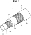
- the shaft extends from the base end to the tip thereof, and is formed on an inner layer forming the main lumen, a first reinforcing layer formed on the inner layer, and an intermediate layer formed on the first reinforcing layer and containing the sub-lumen. It is characterized in that a layer, a second reinforcing layer formed on the intermediate layer, and an outer layer formed on the second reinforcing layer are laminated.
- the shaft constituting the guiding catheter is reinforced by two reinforcing layers (first reinforcing layer and second reinforcing layer) formed from the base end to the tip thereof. It is possible to exhibit excellent torque transmission as compared with a conventional guiding catheter.
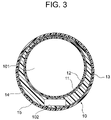
- the main lumen is eccentric with respect to the central axis of the shaft, and the sub-lumen is formed on the side opposite to the side on which the main lumen is eccentric.
- the cross section of the lumen is preferably substantially rectangular or crescent-shaped.
- the diameter of the shaft can be sufficiently reduced.
- the fact that the sublumen is shaped so as to be located on the outside of the bent or curved shape facilitates shaping (makes it easy to bend) and also makes the sublumen easier to bend. It is preferable from the viewpoint of preventing crushing.
- the guiding catheter of the present invention has better torque transmission than the conventionally known guiding catheter with a balloon, and the sublumen does not collapse even if the shaft bends.
- the guiding catheter of the present embodiment is a guiding catheter for inserting a tubular medical device used for endovascular treatment and delivering it to a predetermined position in the body.
- the shaft 10 includes an inner layer 11 that partitions the main lumen 101 from its base end to its tip, a first blade layer 12 formed on the inner layer 11, and a first blade layer 12 so as to include a sub-lumen 102.
- the intermediate layer 13 formed above, the second blade layer 14 formed on the intermediate layer 13, and the outer layer 15 formed on the second blade layer 14 are laminated.
- the guiding catheter 100 includes a shaft 10, a balloon 20, and a tip tip 30. And a hub 40.
- the first blade layer 12 is formed on the outer periphery of the inner layer 11.
- the first blade layer 12 is made of a braided tube formed continuously from the base end to the tip end of the shaft 10 by knitting a metal wire such as stainless steel.
- the outer diameter (wire diameter), the number of hits, the number of holdings, and the like of the metal wire constituting the braided tube can be appropriately adjusted according to the required reinforcing performance.
- the cross-sectional shape of the metal wire is not limited to a circle and may be a rectangle.
- the thickness of the first blade layer 12 is usually 20 to 100 ⁇ m, preferably 30 to 60 ⁇ m.
- the hardness of the outer layer 15 is preferably 40 to 80 as measured by a D-type hardness tester.
- the outer layer 15 may be made of a resin having the same hardness along the axial direction, but may be integrally formed by using resins having different hardness along the axial direction.
- the tip portion of the shaft 10 is shaped into a bent shape.
- the sub-lumen 102 thin portion of the intermediate layer 13
- the thin portion of the intermediate layer 13 is located on the inside (inner peripheral side) of the bent shape.
- a side hole 103 communicating with the sub-lumen 102 is formed on the outer peripheral surface of the shaft 10 at the tip end portion where the balloon 20 is mounted. As a result, the expansion fluid flowing through the sub-lumen 102 can flow out to the outside of the shaft 10 (inside the balloon 20) through the side hole 103.
- a balloon 20 is attached to the tip of the shaft 10.
- the balloon 20 flows through the sublumen 102 of the shaft 10 and is expanded by the fluid flowing out of the side hole 103.
- the fluid include physiological saline and a contrast medium.
- constituent material of the balloon 20 examples include thermoplastic resins such as polyamide, polyether polyamide, PEBAX, nylon and polyurethane.
- the diameter (maximum expansion diameter) of the balloon 20 at the time of expansion is usually 5 to 20 mm, preferably 8 to 15 mm.
- a ring-shaped contrast marker 50 is inserted into the lumen 301 of the tip tip 30 at the proximal end portion 31.
- the constituent material of the contrast marker 50 include platinum and platinum-based alloys.
- the inner diameter of the contrast marker 50 is the same as the diameter of the main lumen 101 of the shaft 10.
- the diameter of the lumen 301 (excluding the region where the contrast marker 50 is inserted) of the tip 30 is the same as the diameter of the main lumen 101 of the shaft 10.
- the diameter of the lumen 301 in the region where the contrast marker 50 is inserted is slightly larger than the diameter of the main lumen 101 of the shaft 10, and after the contrast marker 50 is inserted into the lumen 301, the main lumen 101 of the shaft 10
- the forming surface, the inner peripheral surface of the contrast marker 50, and the forming surface of the lumen 301 are flush with each other. As a result, since there is no step between the main lumen 101 of the shaft 10 and the lumen 301 of the tip tip 30, a tubular medical device can be smoothly inserted.
- Examples of the constituent material of the tip tip 30 include the same resin as the resin constituting the intermediate layer 13 and the outer layer 15 of the shaft 10.
- the hardness of the tip 30 is lower than the hardness of the shaft 10 (outer layer 15), whereby the guiding catheter 100 to which flexibility is given to the tip portion has excellent followability to the blood vessel shape. ..
- a hub 40 is connected to the base end side of the shaft 10. As shown in FIG. 1, the hub 40 has a main port 41 communicating with the main lumen 101 and an expansion port 43 communicating with the sublumen 102.
- the shaft 10 is being inserted through the blood vessel.
- the sublumen 102 does not collapse even if it bends.
- the guide wire shaft of the present invention is not limited to this, and various modifications can be made.
- the cross-sectional shape of the sublumen does not have to be rectangular, and may be, for example, crescent-shaped or circular.
- the shaft instead of the first blade layer 12 and the second blade layer 14, the shaft may be reinforced by two coil layers (first coil layer and second coil layer). In this case, by reversing the winding direction of the coil constituting the first coil layer and the winding direction of the coil constituting the second reinforcing layer, excellent torque transmission that does not affect the rotation direction is exhibited. be able to.
- Example 1 An inner layer 11 having an inner diameter of 2.24 mm and a thickness of 30 ⁇ m made of PTFE, a first blade layer 12 having a thickness of 40 ⁇ m made of a braided tube (16 strokes, 1 holding number) woven with stainless steel wire, and a rectangular cross section.
- a second blade with a thickness of 40 ⁇ m consisting of an intermediate layer 13 made of PEBAX containing a (0.30 mm ⁇ 0.90 mm) sublumen 102 and a braided tube (16 shots, 1 holding number) woven with stainless steel wire.
- the guide wire shaft according to the first embodiment has significantly superior torque transmission property as compared with the guide wire shaft according to the comparative example 1.
- the comparative guide wire shaft manufactured by forming the shaft without arranging the first blade layer 12 was also evaluated in the same manner as above, but the torque was compared with that of the guide wire shaft according to the first embodiment. It was inferior in transmission.
Landscapes
- Health & Medical Sciences (AREA)
- Life Sciences & Earth Sciences (AREA)
- Biophysics (AREA)
- Pulmonology (AREA)
- Engineering & Computer Science (AREA)
- Anesthesiology (AREA)
- Biomedical Technology (AREA)
- Heart & Thoracic Surgery (AREA)
- Hematology (AREA)
- Animal Behavior & Ethology (AREA)
- General Health & Medical Sciences (AREA)
- Public Health (AREA)
- Veterinary Medicine (AREA)
- Physics & Mathematics (AREA)
- Geometry (AREA)
- Media Introduction/Drainage Providing Device (AREA)
Priority Applications (4)
| Application Number | Priority Date | Filing Date | Title |
|---|---|---|---|
| DE112020007722.5T DE112020007722T5 (de) | 2020-10-23 | 2020-10-23 | Führungskatheter |
| US18/026,923 US20230321396A1 (en) | 2020-10-23 | 2020-10-23 | Guiding catheter |
| PCT/JP2020/039980 WO2022085199A1 (ja) | 2020-10-23 | 2020-10-23 | ガイディングカテーテル |
| JP2022556365A JPWO2022085199A1 (https=) | 2020-10-23 | 2020-10-23 |
Applications Claiming Priority (1)
| Application Number | Priority Date | Filing Date | Title |
|---|---|---|---|
| PCT/JP2020/039980 WO2022085199A1 (ja) | 2020-10-23 | 2020-10-23 | ガイディングカテーテル |
Publications (1)
| Publication Number | Publication Date |
|---|---|
| WO2022085199A1 true WO2022085199A1 (ja) | 2022-04-28 |
Family
ID=81290314
Family Applications (1)
| Application Number | Title | Priority Date | Filing Date |
|---|---|---|---|
| PCT/JP2020/039980 Ceased WO2022085199A1 (ja) | 2020-10-23 | 2020-10-23 | ガイディングカテーテル |
Country Status (4)
| Country | Link |
|---|---|
| US (1) | US20230321396A1 (https=) |
| JP (1) | JPWO2022085199A1 (https=) |
| DE (1) | DE112020007722T5 (https=) |
| WO (1) | WO2022085199A1 (https=) |
Cited By (1)
| Publication number | Priority date | Publication date | Assignee | Title |
|---|---|---|---|---|
| DE112024002613T5 (de) | 2023-09-29 | 2026-04-02 | Japan Lifeline Co., Ltd. | Kathetervorrichtung |
Families Citing this family (1)
| Publication number | Priority date | Publication date | Assignee | Title |
|---|---|---|---|---|
| CN119733154B (zh) * | 2025-03-05 | 2025-05-06 | 杭州亿科医疗科技有限公司 | 血管介入导管 |
Citations (8)
| Publication number | Priority date | Publication date | Assignee | Title |
|---|---|---|---|---|
| JPH02209159A (ja) * | 1989-01-27 | 1990-08-20 | Vas Cath Inc | 多重ルーメンカテーテル |
| JPH07265433A (ja) * | 1994-03-30 | 1995-10-17 | Nippon Zeon Co Ltd | ガイディングカテーテル |
| JPH10286308A (ja) * | 1997-04-15 | 1998-10-27 | Terumo Corp | 医療用チューブ |
| JPH11507251A (ja) * | 1995-06-07 | 1999-06-29 | カーディマ・インコーポレイテッド | 冠状静脈洞用のガイドカテーテル |
| JP2013066720A (ja) * | 2011-09-23 | 2013-04-18 | Tyco Healthcare Group Lp | 遠位アクセスバルーンガイドカテーテル |
| JP2016116814A (ja) * | 2014-12-24 | 2016-06-30 | 住友ベークライト株式会社 | バルーンカテーテル |
| JP2016527013A (ja) * | 2013-07-24 | 2016-09-08 | 王亮 | 接触制限型サイドバルーン及びダブルホールを有する尿道カテーテル |
| JP2017093903A (ja) * | 2015-11-26 | 2017-06-01 | クリエートメディック株式会社 | カテーテル |
Family Cites Families (7)
| Publication number | Priority date | Publication date | Assignee | Title |
|---|---|---|---|---|
| US6270477B1 (en) | 1996-05-20 | 2001-08-07 | Percusurge, Inc. | Catheter for emboli containment |
| US5782811A (en) * | 1996-05-30 | 1998-07-21 | Target Therapeutics, Inc. | Kink-resistant braided catheter with distal side holes |
| US8221348B2 (en) * | 2005-07-07 | 2012-07-17 | St. Jude Medical, Cardiology Division, Inc. | Embolic protection device and methods of use |
| JP2012196498A (ja) * | 2012-06-14 | 2012-10-18 | Asahi Intecc Co Ltd | 医療用チューブ |
| US9868242B2 (en) * | 2014-04-25 | 2018-01-16 | Medtronic Ablation Frontiers Llc | Methods of manufacturing a multi-lumen device |
| KR102097676B1 (ko) * | 2016-09-01 | 2020-04-06 | 아사히 인텍크 가부시키가이샤 | 카테터 |
| US20220031342A1 (en) * | 2020-07-29 | 2022-02-03 | Neuravi Limited | Balloon Guide Catheter Having Reduced Outer Diameter Distal and Proximal Bonding Interface Areas With the Balloon |
-
2020
- 2020-10-23 DE DE112020007722.5T patent/DE112020007722T5/de active Pending
- 2020-10-23 US US18/026,923 patent/US20230321396A1/en active Pending
- 2020-10-23 WO PCT/JP2020/039980 patent/WO2022085199A1/ja not_active Ceased
- 2020-10-23 JP JP2022556365A patent/JPWO2022085199A1/ja active Pending
Patent Citations (8)
| Publication number | Priority date | Publication date | Assignee | Title |
|---|---|---|---|---|
| JPH02209159A (ja) * | 1989-01-27 | 1990-08-20 | Vas Cath Inc | 多重ルーメンカテーテル |
| JPH07265433A (ja) * | 1994-03-30 | 1995-10-17 | Nippon Zeon Co Ltd | ガイディングカテーテル |
| JPH11507251A (ja) * | 1995-06-07 | 1999-06-29 | カーディマ・インコーポレイテッド | 冠状静脈洞用のガイドカテーテル |
| JPH10286308A (ja) * | 1997-04-15 | 1998-10-27 | Terumo Corp | 医療用チューブ |
| JP2013066720A (ja) * | 2011-09-23 | 2013-04-18 | Tyco Healthcare Group Lp | 遠位アクセスバルーンガイドカテーテル |
| JP2016527013A (ja) * | 2013-07-24 | 2016-09-08 | 王亮 | 接触制限型サイドバルーン及びダブルホールを有する尿道カテーテル |
| JP2016116814A (ja) * | 2014-12-24 | 2016-06-30 | 住友ベークライト株式会社 | バルーンカテーテル |
| JP2017093903A (ja) * | 2015-11-26 | 2017-06-01 | クリエートメディック株式会社 | カテーテル |
Cited By (1)
| Publication number | Priority date | Publication date | Assignee | Title |
|---|---|---|---|---|
| DE112024002613T5 (de) | 2023-09-29 | 2026-04-02 | Japan Lifeline Co., Ltd. | Kathetervorrichtung |
Also Published As
| Publication number | Publication date |
|---|---|
| DE112020007722T5 (de) | 2023-08-10 |
| US20230321396A1 (en) | 2023-10-12 |
| JPWO2022085199A1 (https=) | 2022-04-28 |
Similar Documents
| Publication | Publication Date | Title |
|---|---|---|
| JP6343009B2 (ja) | 低輪郭閉塞カテーテル | |
| US10695531B2 (en) | Balloon catheter and medical elongated body | |
| US11369392B2 (en) | Intravascular catheter with fluoroscopically visible indicium of rotational orientation | |
| US10335575B2 (en) | Medical elongated body | |
| JP6031087B2 (ja) | バルーンカテーテル | |
| KR102149574B1 (ko) | 벌룬 카테터 | |
| EP2517749A1 (en) | Catheter | |
| US10441299B2 (en) | Catheter with deflectable tip | |
| US6740073B1 (en) | Guiding catheter reinforcement with angled distal end | |
| RU2728692C2 (ru) | Головка микрокатетера для эмболизации, содержащая щелевую структуру | |
| EP2000169A9 (en) | Catheter for blood removal | |
| WO2020153208A1 (ja) | カテーテル | |
| JP4544526B2 (ja) | カテーテル | |
| WO2022085199A1 (ja) | ガイディングカテーテル | |
| CN113613702B (zh) | 球囊导管 | |
| US20120065621A1 (en) | Double lumen tubing with improved kinking resistance | |
| US9095374B2 (en) | Catheter with deflectable tip | |
| US20190015629A1 (en) | Multi-Lumen Catheters for Small Body Vessel Applications | |
| US20190091064A1 (en) | Medical catheter for hypothermic treatment | |
| JP6804802B2 (ja) | バルーンカテーテル | |
| KR102852103B1 (ko) | 스테인리스 링을 구비하는 말단 각도 조절이 가능한 카테터 장치 및 이를 이용하는 방법 | |
| JP2018201575A (ja) | カテーテルおよびその製造方法 | |
| WO2024202776A1 (ja) | バルーンカテーテル | |
| JP2024066603A (ja) | カテーテル | |
| WO2025047651A1 (ja) | カテーテル |
Legal Events
| Date | Code | Title | Description |
|---|---|---|---|
| 121 | Ep: the epo has been informed by wipo that ep was designated in this application |
Ref document number: 20958747 Country of ref document: EP Kind code of ref document: A1 |
|
| ENP | Entry into the national phase |
Ref document number: 2022556365 Country of ref document: JP Kind code of ref document: A |
|
| 122 | Ep: pct application non-entry in european phase |
Ref document number: 20958747 Country of ref document: EP Kind code of ref document: A1 |