WO2022080425A1 - 車両用ランプとその制御装置及び制御方法 - Google Patents
車両用ランプとその制御装置及び制御方法 Download PDFInfo
- Publication number
- WO2022080425A1 WO2022080425A1 PCT/JP2021/037937 JP2021037937W WO2022080425A1 WO 2022080425 A1 WO2022080425 A1 WO 2022080425A1 JP 2021037937 W JP2021037937 W JP 2021037937W WO 2022080425 A1 WO2022080425 A1 WO 2022080425A1
- Authority
- WO
- WIPO (PCT)
- Prior art keywords
- lamp
- control
- unit
- camera
- light
- Prior art date
- Legal status (The legal status is an assumption and is not a legal conclusion. Google has not performed a legal analysis and makes no representation as to the accuracy of the status listed.)
- Ceased
Links
Images






Classifications
-
- B—PERFORMING OPERATIONS; TRANSPORTING
- B60—VEHICLES IN GENERAL
- B60Q—ARRANGEMENT OF SIGNALLING OR LIGHTING DEVICES, THE MOUNTING OR SUPPORTING THEREOF OR CIRCUITS THEREFOR, FOR VEHICLES IN GENERAL
- B60Q1/00—Arrangement of optical signalling or lighting devices, the mounting or supporting thereof or circuits therefor
- B60Q1/0017—Devices integrating an element dedicated to another function
- B60Q1/0023—Devices integrating an element dedicated to another function the element being a sensor, e.g. distance sensor, camera
-
- B—PERFORMING OPERATIONS; TRANSPORTING
- B60—VEHICLES IN GENERAL
- B60Q—ARRANGEMENT OF SIGNALLING OR LIGHTING DEVICES, THE MOUNTING OR SUPPORTING THEREOF OR CIRCUITS THEREFOR, FOR VEHICLES IN GENERAL
- B60Q1/00—Arrangement of optical signalling or lighting devices, the mounting or supporting thereof or circuits therefor
- B60Q1/02—Arrangement of optical signalling or lighting devices, the mounting or supporting thereof or circuits therefor the devices being primarily intended to illuminate the way ahead or to illuminate other areas of way or environments
- B60Q1/04—Arrangement of optical signalling or lighting devices, the mounting or supporting thereof or circuits therefor the devices being primarily intended to illuminate the way ahead or to illuminate other areas of way or environments the devices being headlights
- B60Q1/06—Arrangement of optical signalling or lighting devices, the mounting or supporting thereof or circuits therefor the devices being primarily intended to illuminate the way ahead or to illuminate other areas of way or environments the devices being headlights adjustable, e.g. remotely-controlled from inside vehicle
- B60Q1/076—Arrangement of optical signalling or lighting devices, the mounting or supporting thereof or circuits therefor the devices being primarily intended to illuminate the way ahead or to illuminate other areas of way or environments the devices being headlights adjustable, e.g. remotely-controlled from inside vehicle by electrical means including means to transmit the movements, e.g. shafts or joints
-
- B—PERFORMING OPERATIONS; TRANSPORTING
- B60—VEHICLES IN GENERAL
- B60Q—ARRANGEMENT OF SIGNALLING OR LIGHTING DEVICES, THE MOUNTING OR SUPPORTING THEREOF OR CIRCUITS THEREFOR, FOR VEHICLES IN GENERAL
- B60Q1/00—Arrangement of optical signalling or lighting devices, the mounting or supporting thereof or circuits therefor
- B60Q1/02—Arrangement of optical signalling or lighting devices, the mounting or supporting thereof or circuits therefor the devices being primarily intended to illuminate the way ahead or to illuminate other areas of way or environments
- B60Q1/04—Arrangement of optical signalling or lighting devices, the mounting or supporting thereof or circuits therefor the devices being primarily intended to illuminate the way ahead or to illuminate other areas of way or environments the devices being headlights
- B60Q1/06—Arrangement of optical signalling or lighting devices, the mounting or supporting thereof or circuits therefor the devices being primarily intended to illuminate the way ahead or to illuminate other areas of way or environments the devices being headlights adjustable, e.g. remotely-controlled from inside vehicle
- B60Q1/08—Arrangement of optical signalling or lighting devices, the mounting or supporting thereof or circuits therefor the devices being primarily intended to illuminate the way ahead or to illuminate other areas of way or environments the devices being headlights adjustable, e.g. remotely-controlled from inside vehicle automatically
-
- B—PERFORMING OPERATIONS; TRANSPORTING
- B60—VEHICLES IN GENERAL
- B60Q—ARRANGEMENT OF SIGNALLING OR LIGHTING DEVICES, THE MOUNTING OR SUPPORTING THEREOF OR CIRCUITS THEREFOR, FOR VEHICLES IN GENERAL
- B60Q1/00—Arrangement of optical signalling or lighting devices, the mounting or supporting thereof or circuits therefor
- B60Q1/02—Arrangement of optical signalling or lighting devices, the mounting or supporting thereof or circuits therefor the devices being primarily intended to illuminate the way ahead or to illuminate other areas of way or environments
- B60Q1/04—Arrangement of optical signalling or lighting devices, the mounting or supporting thereof or circuits therefor the devices being primarily intended to illuminate the way ahead or to illuminate other areas of way or environments the devices being headlights
- B60Q1/06—Arrangement of optical signalling or lighting devices, the mounting or supporting thereof or circuits therefor the devices being primarily intended to illuminate the way ahead or to illuminate other areas of way or environments the devices being headlights adjustable, e.g. remotely-controlled from inside vehicle
- B60Q1/08—Arrangement of optical signalling or lighting devices, the mounting or supporting thereof or circuits therefor the devices being primarily intended to illuminate the way ahead or to illuminate other areas of way or environments the devices being headlights adjustable, e.g. remotely-controlled from inside vehicle automatically
- B60Q1/085—Arrangement of optical signalling or lighting devices, the mounting or supporting thereof or circuits therefor the devices being primarily intended to illuminate the way ahead or to illuminate other areas of way or environments the devices being headlights adjustable, e.g. remotely-controlled from inside vehicle automatically due to special conditions, e.g. adverse weather, type of road, badly illuminated road signs or potential dangers
-
- B—PERFORMING OPERATIONS; TRANSPORTING
- B60—VEHICLES IN GENERAL
- B60Q—ARRANGEMENT OF SIGNALLING OR LIGHTING DEVICES, THE MOUNTING OR SUPPORTING THEREOF OR CIRCUITS THEREFOR, FOR VEHICLES IN GENERAL
- B60Q1/00—Arrangement of optical signalling or lighting devices, the mounting or supporting thereof or circuits therefor
- B60Q1/02—Arrangement of optical signalling or lighting devices, the mounting or supporting thereof or circuits therefor the devices being primarily intended to illuminate the way ahead or to illuminate other areas of way or environments
- B60Q1/04—Arrangement of optical signalling or lighting devices, the mounting or supporting thereof or circuits therefor the devices being primarily intended to illuminate the way ahead or to illuminate other areas of way or environments the devices being headlights
- B60Q1/06—Arrangement of optical signalling or lighting devices, the mounting or supporting thereof or circuits therefor the devices being primarily intended to illuminate the way ahead or to illuminate other areas of way or environments the devices being headlights adjustable, e.g. remotely-controlled from inside vehicle
- B60Q1/08—Arrangement of optical signalling or lighting devices, the mounting or supporting thereof or circuits therefor the devices being primarily intended to illuminate the way ahead or to illuminate other areas of way or environments the devices being headlights adjustable, e.g. remotely-controlled from inside vehicle automatically
- B60Q1/10—Arrangement of optical signalling or lighting devices, the mounting or supporting thereof or circuits therefor the devices being primarily intended to illuminate the way ahead or to illuminate other areas of way or environments the devices being headlights adjustable, e.g. remotely-controlled from inside vehicle automatically due to vehicle inclination, e.g. due to load distribution
-
- B—PERFORMING OPERATIONS; TRANSPORTING
- B60—VEHICLES IN GENERAL
- B60Q—ARRANGEMENT OF SIGNALLING OR LIGHTING DEVICES, THE MOUNTING OR SUPPORTING THEREOF OR CIRCUITS THEREFOR, FOR VEHICLES IN GENERAL
- B60Q1/00—Arrangement of optical signalling or lighting devices, the mounting or supporting thereof or circuits therefor
- B60Q1/02—Arrangement of optical signalling or lighting devices, the mounting or supporting thereof or circuits therefor the devices being primarily intended to illuminate the way ahead or to illuminate other areas of way or environments
- B60Q1/04—Arrangement of optical signalling or lighting devices, the mounting or supporting thereof or circuits therefor the devices being primarily intended to illuminate the way ahead or to illuminate other areas of way or environments the devices being headlights
- B60Q1/14—Arrangement of optical signalling or lighting devices, the mounting or supporting thereof or circuits therefor the devices being primarily intended to illuminate the way ahead or to illuminate other areas of way or environments the devices being headlights having dimming means
- B60Q1/1415—Dimming circuits
- B60Q1/1423—Automatic dimming circuits, i.e. switching between high beam and low beam due to change of ambient light or light level in road traffic
- B60Q1/143—Automatic dimming circuits, i.e. switching between high beam and low beam due to change of ambient light or light level in road traffic combined with another condition, e.g. using vehicle recognition from camera images or activation of wipers
-
- B—PERFORMING OPERATIONS; TRANSPORTING
- B60—VEHICLES IN GENERAL
- B60Q—ARRANGEMENT OF SIGNALLING OR LIGHTING DEVICES, THE MOUNTING OR SUPPORTING THEREOF OR CIRCUITS THEREFOR, FOR VEHICLES IN GENERAL
- B60Q1/00—Arrangement of optical signalling or lighting devices, the mounting or supporting thereof or circuits therefor
- B60Q1/26—Arrangement of optical signalling or lighting devices, the mounting or supporting thereof or circuits therefor the devices being primarily intended to indicate the vehicle, or parts thereof, or to give signals, to other traffic
- B60Q1/34—Arrangement of optical signalling or lighting devices, the mounting or supporting thereof or circuits therefor the devices being primarily intended to indicate the vehicle, or parts thereof, or to give signals, to other traffic for indicating change of drive direction
-
- F—MECHANICAL ENGINEERING; LIGHTING; HEATING; WEAPONS; BLASTING
- F21—LIGHTING
- F21S—NON-PORTABLE LIGHTING DEVICES; SYSTEMS THEREOF; VEHICLE LIGHTING DEVICES SPECIALLY ADAPTED FOR VEHICLE EXTERIORS
- F21S41/00—Illuminating devices specially adapted for vehicle exteriors, e.g. headlamps
- F21S41/60—Illuminating devices specially adapted for vehicle exteriors, e.g. headlamps characterised by a variable light distribution
- F21S41/65—Illuminating devices specially adapted for vehicle exteriors, e.g. headlamps characterised by a variable light distribution by acting on light sources
- F21S41/657—Illuminating devices specially adapted for vehicle exteriors, e.g. headlamps characterised by a variable light distribution by acting on light sources by moving light sources
-
- F—MECHANICAL ENGINEERING; LIGHTING; HEATING; WEAPONS; BLASTING
- F21—LIGHTING
- F21S—NON-PORTABLE LIGHTING DEVICES; SYSTEMS THEREOF; VEHICLE LIGHTING DEVICES SPECIALLY ADAPTED FOR VEHICLE EXTERIORS
- F21S45/00—Arrangements within vehicle lighting devices specially adapted for vehicle exteriors, for purposes other than emission or distribution of light
- F21S45/70—Prevention of harmful light leakage
-
- H—ELECTRICITY
- H04—ELECTRIC COMMUNICATION TECHNIQUE
- H04N—PICTORIAL COMMUNICATION, e.g. TELEVISION
- H04N23/00—Cameras or camera modules comprising electronic image sensors; Control thereof
- H04N23/56—Cameras or camera modules comprising electronic image sensors; Control thereof provided with illuminating means
-
- H—ELECTRICITY
- H04—ELECTRIC COMMUNICATION TECHNIQUE
- H04N—PICTORIAL COMMUNICATION, e.g. TELEVISION
- H04N23/00—Cameras or camera modules comprising electronic image sensors; Control thereof
- H04N23/60—Control of cameras or camera modules
- H04N23/61—Control of cameras or camera modules based on recognised objects
-
- H—ELECTRICITY
- H04—ELECTRIC COMMUNICATION TECHNIQUE
- H04N—PICTORIAL COMMUNICATION, e.g. TELEVISION
- H04N23/00—Cameras or camera modules comprising electronic image sensors; Control thereof
- H04N23/70—Circuitry for compensating brightness variation in the scene
- H04N23/74—Circuitry for compensating brightness variation in the scene by influencing the scene brightness using illuminating means
-
- B—PERFORMING OPERATIONS; TRANSPORTING
- B60—VEHICLES IN GENERAL
- B60Q—ARRANGEMENT OF SIGNALLING OR LIGHTING DEVICES, THE MOUNTING OR SUPPORTING THEREOF OR CIRCUITS THEREFOR, FOR VEHICLES IN GENERAL
- B60Q2300/00—Indexing codes for automatically adjustable headlamps or automatically dimmable headlamps
- B60Q2300/05—Special features for controlling or switching of the light beam
- B60Q2300/056—Special anti-blinding beams, e.g. a standard beam is chopped or moved in order not to blind
-
- B—PERFORMING OPERATIONS; TRANSPORTING
- B60—VEHICLES IN GENERAL
- B60Q—ARRANGEMENT OF SIGNALLING OR LIGHTING DEVICES, THE MOUNTING OR SUPPORTING THEREOF OR CIRCUITS THEREFOR, FOR VEHICLES IN GENERAL
- B60Q2300/00—Indexing codes for automatically adjustable headlamps or automatically dimmable headlamps
- B60Q2300/40—Indexing codes relating to other road users or special conditions
- B60Q2300/41—Indexing codes relating to other road users or special conditions preceding vehicle
-
- B—PERFORMING OPERATIONS; TRANSPORTING
- B60—VEHICLES IN GENERAL
- B60Q—ARRANGEMENT OF SIGNALLING OR LIGHTING DEVICES, THE MOUNTING OR SUPPORTING THEREOF OR CIRCUITS THEREFOR, FOR VEHICLES IN GENERAL
- B60Q2300/00—Indexing codes for automatically adjustable headlamps or automatically dimmable headlamps
- B60Q2300/40—Indexing codes relating to other road users or special conditions
- B60Q2300/42—Indexing codes relating to other road users or special conditions oncoming vehicle
-
- B—PERFORMING OPERATIONS; TRANSPORTING
- B60—VEHICLES IN GENERAL
- B60Q—ARRANGEMENT OF SIGNALLING OR LIGHTING DEVICES, THE MOUNTING OR SUPPORTING THEREOF OR CIRCUITS THEREFOR, FOR VEHICLES IN GENERAL
- B60Q2300/00—Indexing codes for automatically adjustable headlamps or automatically dimmable headlamps
- B60Q2300/40—Indexing codes relating to other road users or special conditions
- B60Q2300/45—Special conditions, e.g. pedestrians, road signs or potential dangers
-
- B—PERFORMING OPERATIONS; TRANSPORTING
- B60—VEHICLES IN GENERAL
- B60Q—ARRANGEMENT OF SIGNALLING OR LIGHTING DEVICES, THE MOUNTING OR SUPPORTING THEREOF OR CIRCUITS THEREFOR, FOR VEHICLES IN GENERAL
- B60Q2400/00—Special features or arrangements of exterior signal lamps for vehicles
- B60Q2400/30—Daytime running lights [DRL], e.g. circuits or arrangements therefor
-
- B—PERFORMING OPERATIONS; TRANSPORTING
- B60—VEHICLES IN GENERAL
- B60R—VEHICLES, VEHICLE FITTINGS, OR VEHICLE PARTS, NOT OTHERWISE PROVIDED FOR
- B60R2300/00—Details of viewing arrangements using cameras and displays, specially adapted for use in a vehicle
- B60R2300/40—Details of viewing arrangements using cameras and displays, specially adapted for use in a vehicle characterised by the details of the power supply or the coupling to vehicle components
- B60R2300/404—Details of viewing arrangements using cameras and displays, specially adapted for use in a vehicle characterised by the details of the power supply or the coupling to vehicle components triggering from stand-by mode to operation mode
-
- F—MECHANICAL ENGINEERING; LIGHTING; HEATING; WEAPONS; BLASTING
- F21—LIGHTING
- F21S—NON-PORTABLE LIGHTING DEVICES; SYSTEMS THEREOF; VEHICLE LIGHTING DEVICES SPECIALLY ADAPTED FOR VEHICLE EXTERIORS
- F21S41/00—Illuminating devices specially adapted for vehicle exteriors, e.g. headlamps
- F21S41/10—Illuminating devices specially adapted for vehicle exteriors, e.g. headlamps characterised by the light source
- F21S41/14—Illuminating devices specially adapted for vehicle exteriors, e.g. headlamps characterised by the light source characterised by the type of light source
- F21S41/141—Light emitting diodes [LED]
- F21S41/151—Light emitting diodes [LED] arranged in one or more lines
- F21S41/153—Light emitting diodes [LED] arranged in one or more lines arranged in a matrix
-
- F—MECHANICAL ENGINEERING; LIGHTING; HEATING; WEAPONS; BLASTING
- F21—LIGHTING
- F21S—NON-PORTABLE LIGHTING DEVICES; SYSTEMS THEREOF; VEHICLE LIGHTING DEVICES SPECIALLY ADAPTED FOR VEHICLE EXTERIORS
- F21S43/00—Signalling devices specially adapted for vehicle exteriors, e.g. brake lamps, direction indicator lights or reversing lights
- F21S43/50—Signalling devices specially adapted for vehicle exteriors, e.g. brake lamps, direction indicator lights or reversing lights characterised by aesthetic components not otherwise provided for, e.g. decorative trim, partition walls or covers
-
- F—MECHANICAL ENGINEERING; LIGHTING; HEATING; WEAPONS; BLASTING
- F21—LIGHTING
- F21W—INDEXING SCHEME ASSOCIATED WITH SUBCLASSES F21K, F21L, F21S and F21V, RELATING TO USES OR APPLICATIONS OF LIGHTING DEVICES OR SYSTEMS
- F21W2102/00—Exterior vehicle lighting devices for illuminating purposes
- F21W2102/10—Arrangement or contour of the emitted light
- F21W2102/13—Arrangement or contour of the emitted light for high-beam region or low-beam region
- F21W2102/135—Arrangement or contour of the emitted light for high-beam region or low-beam region the light having cut-off lines, i.e. clear borderlines between emitted regions and dark regions
- F21W2102/14—Arrangement or contour of the emitted light for high-beam region or low-beam region the light having cut-off lines, i.e. clear borderlines between emitted regions and dark regions having vertical cut-off lines; specially adapted for adaptive high beams, i.e. wherein the beam is broader but avoids glaring other road users
-
- F—MECHANICAL ENGINEERING; LIGHTING; HEATING; WEAPONS; BLASTING
- F21—LIGHTING
- F21W—INDEXING SCHEME ASSOCIATED WITH SUBCLASSES F21K, F21L, F21S and F21V, RELATING TO USES OR APPLICATIONS OF LIGHTING DEVICES OR SYSTEMS
- F21W2102/00—Exterior vehicle lighting devices for illuminating purposes
- F21W2102/10—Arrangement or contour of the emitted light
- F21W2102/13—Arrangement or contour of the emitted light for high-beam region or low-beam region
- F21W2102/135—Arrangement or contour of the emitted light for high-beam region or low-beam region the light having cut-off lines, i.e. clear borderlines between emitted regions and dark regions
- F21W2102/155—Arrangement or contour of the emitted light for high-beam region or low-beam region the light having cut-off lines, i.e. clear borderlines between emitted regions and dark regions having inclined and horizontal cutoff lines
-
- F—MECHANICAL ENGINEERING; LIGHTING; HEATING; WEAPONS; BLASTING
- F21—LIGHTING
- F21W—INDEXING SCHEME ASSOCIATED WITH SUBCLASSES F21K, F21L, F21S and F21V, RELATING TO USES OR APPLICATIONS OF LIGHTING DEVICES OR SYSTEMS
- F21W2102/00—Exterior vehicle lighting devices for illuminating purposes
- F21W2102/10—Arrangement or contour of the emitted light
- F21W2102/13—Arrangement or contour of the emitted light for high-beam region or low-beam region
- F21W2102/165—Arrangement or contour of the emitted light for high-beam region or low-beam region the borderlines between emitted regions and dark regions other than cut-off lines being variable
-
- F—MECHANICAL ENGINEERING; LIGHTING; HEATING; WEAPONS; BLASTING
- F21—LIGHTING
- F21Y—INDEXING SCHEME ASSOCIATED WITH SUBCLASSES F21K, F21L, F21S and F21V, RELATING TO THE FORM OR THE KIND OF THE LIGHT SOURCES OR OF THE COLOUR OF THE LIGHT EMITTED
- F21Y2115/00—Light-generating elements of semiconductor light sources
- F21Y2115/10—Light-emitting diodes [LED]
Definitions
- the present invention relates to a vehicle lamp applied to a headlamp of a vehicle such as an automobile, a control device for controlling the light distribution, and a control method.
- Recent automobile headlamps prevent dazzling of preceding vehicles, oncoming vehicles, or pedestrians (hereinafter referred to as objects), while enhancing the lighting effect in the front area of the vehicle.
- ADB Adaptive Driving Beam: Light distribution
- Patent Document 1 when an object is detected from an image captured by a camera, the position of the object is detected, and the ADB control that controls the irradiation area of the illumination light of the lamp unit based on the detected position is used. It is done.
- this type of headlamp is provided with an aiming adjustment mechanism for adjusting the optical axis direction of the lamp unit.
- a lamp unit is normally mounted on a tiltable bracket, and the optical axis direction of the lamp unit is adjusted by adjusting the forward tilt angle of the bracket.
- the camera is mounted on the same bracket together with the lamp unit, and the optical axis direction of the lamp unit is adjusted and at the same time, the optical axis direction of the camera is aligned with the optical axis direction of the lamp unit. Has been taken.
- Patent Document 2 proposes a headlamp in which a lamp unit and a camera are built in a lamp housing.
- a lamp camera By incorporating such a camera (hereinafter referred to as a lamp camera) in the lamp housing, the irradiation optical axis that irradiates the light of the lamp unit and the image pickup optical axis of the lamp camera can be set at substantially the same height position. can.
- This has the advantage that the viewing angle of each optical axis with respect to the object can be made substantially the same, and ADB control can be facilitated.
- ADB control a low beam light distribution pattern having a required cut-off line (hereinafter, Lo light distribution pattern) and an ADB high beam light distribution pattern that additionally illuminates the upper region of the Lo light distribution pattern (hereinafter, Lo light distribution pattern).
- Lo light distribution pattern a low beam light distribution pattern having a required cut-off line
- Lo light distribution pattern an ADB high beam light distribution pattern that additionally illuminates the upper region of the Lo light distribution pattern
- a form of performing light distribution in which light is combined with the AHi light distribution pattern has been proposed.
- ADB control capable of illuminating as wide an area as possible while preventing dazzling to the object is possible. Can be realized.
- the entire light irradiation area may be deflected up and down without changing the light distribution pattern.
- the control for deflecting the optical axis direction of the lamp unit up and down So-called leveling control is performed. That is, the bracket on which the lamp unit is mounted is configured so that it can be tilted by the leveling actuator, and when required by ADB control, the leveling actuator is driven to tilt the bracket and the lamp unit is moved up and down in the optical axis direction. Try to tilt to. This makes it possible to simplify the processing in ADB control.
- the bracket is tilted to change the optical axis direction of the lamp unit in leveling control
- the optical axis direction of the camera mounted on the bracket is also changed accordingly. Therefore, the position in the image captured by the camera is changed, and it is necessary to correct the position change of the object when detecting the object.
- Leveling control is required to follow changes in the position of the object and control it at high speed, but if the position of the object in the captured image shifts, processing to correct this position is required, and the processing requires processing. It takes time and it becomes difficult to execute high-speed leveling control or ADB control with good followability.
- a light-shielding structure such as a lens hood is attached to the camera built in the lamp housing, or a light-shielding structure is provided in a part of the lamp housing so that light does not leak into the lamp camera.
- a lamp unit that irradiates light over a wide range such as a sign lamp, for example, a headlamp containing a turn signal lamp unit, is wider on the left and right sides of the automobile than a high beam lamp unit or a low beam lamp unit. Since it is configured to irradiate light toward the area, it is easy for the lamp camera to leak light. When such light leakage occurs, it becomes difficult to detect an object by using a lamp camera when the turn signal lamp is lit, and it becomes difficult to control the light distribution of the headlamps appropriately.
- a predetermined margin is provided for the area including the object, and the light distribution control is performed to block a slightly wider area than the object. Therefore, when the position of the object with respect to the vehicle is changed, especially when the position is changed at a speed higher than the control speed of ADB control, a part of the area around the object is not irradiated with light (hereinafter referred to as a dark area). , Called a dark zone) may occur.
- the preceding vehicle Is moved to a region above (far) from the cut-off line of the Lo light distribution pattern. Therefore, the region between the light-shielding region of the AHi light distribution pattern and the upper region of the cut-off line of the Lo light distribution pattern becomes a dark zone. When such a dark zone occurs, it becomes impossible to illuminate the front area of the own vehicle including a part of the preceding vehicle and the area immediately behind the preceding vehicle, which is not preferable for safe driving of the own vehicle.
- a first object of the present invention is to provide a vehicle lamp that enables high-speed leveling control or ADB control, and a control device that controls the light distribution thereof.
- a second object of the present invention is to suppress the influence of light leakage in the lamp camera in a vehicle lamp provided with a lamp camera and a lamp unit, and to detect an object performed in light distribution control with high accuracy, for example.
- a control device for a vehicle lamp is provided.
- a third object of the present invention is to provide a vehicle lamp control method and a control device that enable suitable light distribution control that eliminates the dark zone.
- the vehicle lamp of the present invention is a lamp mounted on a vehicle, and a lamp camera that captures an object existing outside the vehicle in the lamp housing of the lamp. And, a lamp unit that changes and controls the light distribution of the light emitted based on the position information of the object imaged by this lamp camera is built in, and the lamp camera has a predetermined image pickup optical axis based on the vehicle.
- the lamp unit is oriented in the direction, and the lamp unit has a configuration in which the irradiation optical axis is changed and controlled in the vertical direction based on the position information of the object.
- the control device for the vehicle lamp of the present invention has a lamp housing, a lamp camera that captures an object existing outside the vehicle, and the lamp camera.
- the vehicle lamp control device of the present invention includes a lamp control unit for controlling the lighting of the lamp unit and the lamp in the vehicle lamp including the lamp unit and the lamp camera. It includes an object detection unit that detects an object based on an image pickup signal captured by the camera, and a camera control unit that controls the image pickup operation of the lamp camera.
- the camera control unit is characterized in that it performs failure suppression control for suppressing an obstacle in object detection in the object detection unit due to light leakage from the lamp unit to the lamp camera.
- an object is detected from an image captured by a camera, and based on the position information of the detected object, the light distribution pattern of the light to be irradiated and the irradiation optical axis thereof are determined.
- the control method detects an object and a dark zone generated when the detected object is irradiated with light by the lamp unit.
- the dark zone control step includes a dark zone detection step for detecting and a dark zone control step for eliminating the dark zone, and the dark zone control step includes a light distribution pattern control step for controlling the light distribution pattern of the lamp unit and an irradiation light axis of the lamp unit.
- the control device for a vehicle lamp of the present invention is for a vehicle including a lamp unit capable of changing the light distribution pattern of the emitted light and the irradiation optical axis thereof. It is equipped with a lamp and a control unit that detects an object from an image captured by a camera and controls a lamp unit based on the position information of the detected object. The control unit detects and detects the object.
- the object detector that detects the dark zone that occurs when the lamp unit irradiates the object with light, and the light distribution pattern and irradiation light axis of the lamp unit are selectively or integrated based on the detected dark zone. It is equipped with a lamp control unit that controls the light.
- a vehicle lamp that enables high-speed leveling control or ADB control, and a control device that controls the light distribution thereof.
- a vehicle lamp provided with a lamp camera and a lamp unit, it is possible to suppress the influence of light leakage in the lamp camera and, for example, detect an object performed during light distribution control with high accuracy.
- a control device for a vehicle lamp it is possible to provide a vehicle lamp control method and a control device that enable suitable light distribution control that eliminates the dark zone.
- FIG. 1 is a conceptual configuration diagram of an embodiment of a vehicle lamp and its control device.
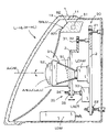
- FIG. 2 is a vertical cross-sectional view of the left headlamp.
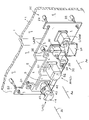
- FIG. 3 is a schematic perspective view of the main configuration of the left headlamp.
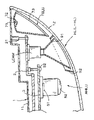
- FIG. 4 is a schematic horizontal sectional view of a part of the left headlamp.
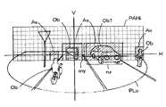
- FIG. 5 is a pattern diagram of a Lo light distribution pattern and an AHi light distribution pattern.
- FIG. 6 is a schematic configuration diagram of the AHi lamp unit.
- FIG. 7A is a schematic diagram of an image captured by the front camera FCAM
- FIG. 7B is a schematic diagram of an image captured by the lamp camera LCAM.
- FIG. 8 (a) is a schematic diagram of a light distribution pattern based on leveling control when a light-shielding region is formed by extinguishing a corresponding pixel element in a unit illumination region in which another vehicle exists.
- Is a schematic diagram of a light distribution pattern based on leveling control when each irradiation optical axis of the Lo lamp unit and the AHi lamp unit is controlled to change downward.
- FIG. 9 is a pattern diagram of the AHi light distribution pattern of the AHi lamp unit of the modified example.
- FIG. 10 is a schematic diagram of a light distribution pattern based on ADB control.
- FIG. 11 is a block configuration diagram of the vehicle ECU.
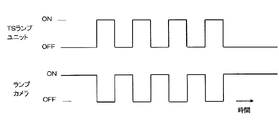
- FIG. 12 is an operation timing diagram of one form of the lamp camera.
- FIG. 13 is an operation timing diagram of another form of the lamp camera.
- FIG. 14 is an operation timing diagram of still another form of the lamp camera.
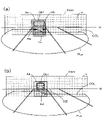
- FIG. 15 (a) is a light distribution pattern diagram illustrating ADB control and a dark zone when a light-shielding region is formed by extinguishing a corresponding pixel element in a unit illumination region in which a preceding vehicle exists.
- (B) is a light distribution pattern diagram illustrating ADB control and a dark zone when the distance between the preceding vehicle and the own vehicle becomes long.
- FIG. 16 is a schematic diagram illustrating a dark zone.
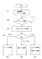
- FIG. 17 is a flow chart of dark zone control.
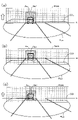
- FIG. 18A is a schematic diagram of a light distribution pattern based on dark zone control when leveling control is performed, and FIG.
- FIG. 18B is a schematic diagram of a light distribution pattern based on dark zone control when light distribution pattern control is performed.
- FIG. 18C is a schematic diagram of a light distribution pattern based on dark zone control when leveling control and light distribution pattern control are performed in a unified manner.
- FIG. 1 is a conceptual configuration diagram of an embodiment of a vehicle lamp and a control device thereof to which the present invention is applied to an automobile headlamp.
- headlamps L-HL and R-HL are installed on the left and right sides of the front part of the vehicle body of the automobile CAR, respectively.
- the left and right headlamps L-HL and R-HL have a symmetrical configuration on the left and right.
- the left and right headlamps may be collectively referred to as a headlamp HL.
- a front camera FCAM is equipped inside the front window FW of the automobile CAR, and it is possible to image a required area in front of the automobile CAR at a required frame rate and a required resolution.
- the front camera FCAM is equipped with an image pickup lens having a predetermined focal length, and the image pickup element has a light receiving sensitivity extending from the visible light region to the infrared light region, so that the object can be captured at high resolution during the daytime or at nighttime. It is possible to take an image with.
- the front camera FCAM is connected to the vehicle ECU (electronic control unit) 100 of the automobile.
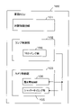
- vehicle ECU 100 is configured as a control means in the present invention, and includes an object detection unit 101, a lamp control unit 102, and a camera control unit 103.
- the object detection unit 101 detects an object by analyzing an image captured by the front camera FCAM. It is also possible to detect an object by performing image analysis on an image captured by a lamp camera LCAM, which will be described later.
- the lamp control unit 102 generates a lamp control signal for controlling the lighting and light distribution of the headlamp HL based on the detected object and outputs the lamp control signal to the headlamp HL.
- the vehicle ECU 100 includes other control units for performing vehicle speed and steering of the automobile CAR and further driving assistance based on the object detected by the object detection unit 101. These control units are of the present invention. Since there is little relation with, the explanation is omitted.
- the camera control unit 103 controls the front camera FCAM and the lamp camera LCAM described later.
- the headlamp HL includes a low beam lamp unit (hereinafter, Lo lamp unit) LoLU and a high beam lamp unit (hereinafter, AHi lamp unit) capable of ADB control. ) AHiLU, a turn signal lamp unit (hereinafter, TS lamp unit) TSLU, and a daytime running lamp unit (hereinafter, DR lamp unit) DRLU that also serves as a clearance lamp, and these lamp units are combined into one lamp housing 1. It is configured as an interior composite headlamp.
- the lamp housing 1 contains a lamp camera LCAM that captures images at a frame rate higher than that of the front camera FCAM, and covers a region in front of the automobile CAM, particularly an region substantially the same as the imaging region of the front camera FCAM. It is possible to take an image. Further, the lamp housing 1 contains a lamp drive module LDM that drives light emission (lighting) of each lamp unit based on the lamp control signal. The lamp camera LCAM and the lamp drive module LDM are connected to the vehicle ECU 100.
- the TS lamp unit TSLU and the DR lamp unit DRLU are fixedly attached to the lamp housing 1.
- the Lo lamp unit LoLU, the AHi lamp unit AHiLU, and the lamp camera LCAM are mounted in the lamp housing 1 in a state in which the directions of the respective optical axes, that is, the irradiation optical axis and the imaging optical axis can be appropriately adjusted.
- FIG. 2 and 3 are views showing a configuration for adjusting each optical axis direction of the Lo lamp unit LoLU, the AHi lamp unit AHiLU, and the lamp camera LCAM
- FIG. 2 is a vertical sectional view of the left headlamp L-HL.
- FIG. 3 is a schematic perspective view.
- the lamp housing 1 is configured to include a container-shaped lamp body 11 having a front opening and a translucent cover 12 attached to the opening of the lamp body 11.
- the TS lamp unit TSLU and the DR lamp unit DRLU are fixedly attached to the lamp body 11 as described above, and are configured to irradiate light through the translucent cover 12 when lit. There is.
- the Lo lamp unit LoLU, the AHi lamp unit AHiLU, and the lamp camera LCAM are mounted on an aiming bracket (first member of the present invention) 2 capable of adjusting the tilt angle.
- the Lo lamp unit LoLU and the A-Hi lamp unit AHiLU are mounted on a leveling bracket (second member of the present invention) 3 configured separately from the aiming bracket 2, and are mounted via the leveling bracket 3. It is supported by the aiming bracket 2.
- the lamp camera LCAM is directly mounted on the aiming bracket 2, and the image pickup optical axis Ac of the lamp camera LCAM is directed at a predetermined angle with respect to the aiming bracket 2.
- the aiming bracket 2 is supported by the lamp body 11 by an aiming mechanism 20 capable of tilting in the vertical direction and the horizontal direction.
- the aiming bracket 2 is supported by the lamp body 11 by the fulcrum portion 21 at one corner portion, and the upper and lower aiming adjustment portions 22 are arranged in a downward part of the fulcrum portion 21, and the fulcrum portion 21.
- the left and right aiming adjustment portions 23 are arranged in a part of the portion 21 in the left direction. Since the fulcrum portion 21 and the upper / lower or left / right aiming adjustment portions 22 and 23 have a known configuration, detailed description thereof will be omitted, but for example, the fulcrum portion 21 and the aiming screw screwed to the aiming screw are configured. ..
- the aiming bracket 2 can adjust the forward tilt angle in the vertical direction and the swing angle in the horizontal direction with the fulcrum portion 21 as a fulcrum.
- the leveling bracket 3 is supported by the aiming bracket 2 by a leveling mechanism 30 capable of tilting in the vertical direction.
- the leveling bracket 3 is supported by the aiming bracket 2 by the fulcrum portions 31 and 32 at the upper edge portion thereof, here, at two positions on the left and right of the upper edge, respectively.
- the leveling actuator LACT supported by the aiming bracket 2 is connected to a part of the lower edge of the leveling bracket 3.
- the leveling actuator LACT is composed of, for example, an electric motor 33 provided with a leveling screw 34, and a leveling nut 35 attached to a part of the lower edge of the leveling bracket 3 is screwed into the leveling actuator LACT.
- the leveling actuator LACT is rotationally driven, the leveling nut 35 screwed to the leveling screw 34 is screwed, and the lower edge portion of the leveling bracket 3 is moved in the front-rear direction accordingly to change the forward tilt angle. Change control.
- the relative forward tilt angle of the leveling bracket 3 with respect to the aiming bracket 2 is set to a predetermined angle, for example, 0 degree.
- the irradiation optical axes Al and Aa of the Lo lamp unit LoLu and the AHi lamp unit AHiLU mounted on the leveling bracket 3 are directed in the same direction as the image pickup optical axis Ac of the lamp camera LCAM, respectively. There is.
- the tilt angle of the aiming bracket 2 by the aiming mechanism 20 by adjusting the tilt angle of the aiming bracket 2 by the aiming mechanism 20, the directions of the optical axes Al, Aa, and Ac of the Lo lamp unit LoLU, the AHi lamp unit AHiLU, and the lamp camera LCAM are collectively adjusted. Can be done. Further, by changing the forward tilt angle of the leveling bracket 3 by the leveling mechanism 30, the optical axis direction of the Lo lamp unit LoLU and the A-Hi lamp unit AHiLU can be changed and controlled at the same time.
- FIG. 4 is a schematic horizontal cross-sectional view of a part of the headlamp HL outside in the vehicle width direction.
- the TS lamp unit TSLU is configured to emit amber-colored light, and is arranged in a region in the lamp housing 1 facing outward in the vehicle width direction, in this case, next to the lamp camera LCAM.
- the TS lamp unit TSLU has an LED (light emitting diode) 71 that emits white light as a light source, a reflector 72 supported by the lamp body 11, and an amber-colored translucency attached to the opening of the reflector 72.
- the inner lens 73 made of resin is provided.
- the inner surface of the reflector 72 is configured as a light reflecting surface by, for example, aluminum coating.
- the TS lamp unit TSLU is controlled by the lamp control unit 102 so that the LED 71 periodically emits light and is lit in a blinking state.
- the TS lamp unit TSLU is turned on and off alternately at a cycle of 1 second. Due to this light emission, the white light from the LED 71 is converted into amber-colored light when passing through the inner lens 73, and is emitted from the headlamp HL.
- the TS lamp unit TSLU may be configured such that the light source is composed of an LED that emits amber-colored light, and the inner lens is composed of a colorless translucent resin to irradiate amber-colored light.
- the DR lamp unit DRLU is composed of a white LED 81 as a light source and a light guide (light guide body) 82 made of a translucent resin, and the light guide 82 is a lamp. It is arranged so as to extend from the upper edge in the housing 1 along the inner edge in the vehicle width direction.
- the white LED 81 is arranged to face the end face of the light guide 82 in the length direction, and the light from the white LED 81 is guided in the length direction of the light guide 82 and directed toward the front of the headlamp HL. It is configured so that the side surface 82a of the light guide 82 is emitted as a light emitting surface.
- the Lo lamp unit LoLU reflects the light of the white LED 41 as a light source by the reflector 42, shields a part of the light by the shade 43, and then directs the light forward by the irradiation lens 44. It is a configuration to irradiate. Since a part of the emitted light is shielded by the shade 43, the light distribution pattern of the light emitted by this Lo lamp unit LoLU has a required cut-off line COL at the upper edge as shown in FIG. It becomes a pattern, a so-called low beam light distribution pattern (hereinafter referred to as Lo light distribution pattern) PLo.
- Lo light distribution pattern a so-called low beam light distribution pattern
- the AHi lamp unit AHiLU includes a multi-division LED array 61 and a projection lens 62 that projects the light emitted by the multi-division LED array 61 toward the front.
- the multi-segment LED array 61 has a configuration in which a large number of micro LED light emitting elements (hereinafter referred to as pixel elements) 61p are arranged in a matrix shape (square shape).
- pixel elements micro LED light emitting elements
- each pixel element 61p is selectively emitted by control by the lamp drive module LDM, and a required emission pattern is formed by the emitted light of the pixel element 61p.
- ADB high beam in which a large number of unit illumination regions u corresponding to each pixel element 61p are synthesized in the upper region of the Lo light distribution pattern PLo.
- a light distribution pattern (hereinafter referred to as AHi light distribution pattern) PAHi is formed.
- the lamp camera LCAM is composed of a camera that captures at least a visible light region and has the same focal length as the front camera FCAM, it is configured to image a front region substantially the same as that of the front camera FCAM. As described above, this lamp camera LCAM can perform imaging at a higher frame rate than the front camera FCAM. On the other hand, in order to reduce the cost of the lamp camera LCAM, its resolution is lower than that of the front camera FCAM. As shown in FIG. 1, the lamp camera LCAM is connected to the vehicle ECU 100 via a LIN (Local Interconnect Network) line 104 deployed in an automobile.
- LIN Local Interconnect Network
- the lamp camera LCAM is a square whose aperture size is gradually increased toward the front, that is, on the side where an image pickup lens (not shown in the figure is arranged) is arranged.
- a light-shielding hood 91 having a weight cylinder shape is arranged.
- the light-shielding hood 91 may have a conical cylinder shape.
- a light-shielding sleeve 92 having a square cylinder shape larger than that of the light-shielding hood 91 is attached so as to project rearward.
- a part of the light-shielding sleeve 92 is arranged so as to overlap the light-shielding hood 91 in the radial direction, and the light-shielding sleeve 91 and the light-shielding hood 92 form a light-shielding labyrinth.
- the lamp drive module LDM has a function of controlling lighting of each of the lamp units TSLU, DRLU, LoLU, and AHiLU by receiving a lamp control signal from the vehicle ECU 100, and a pattern shape of an AHi light distribution pattern performed in the AHi lamp unit AHiLU. It has a function of driving and controlling the multi-segment LED array 61 in order to control the above.
- aiming adjustment is executed when the lamp housing 1 is attached to the vehicle body of the automobile CAR.
- the vertical angle and the horizontal angle of the aiming bracket 2 are adjusted by appropriately operating the vertical aiming adjustment unit 22 and the left / right aiming adjustment unit 23 of the aiming mechanism 20.
- the directions of the irradiation optical axes Al and Aa of the Lo lamp unit LoLU and the AHi lamp unit LAHiLu mounted on the aiming bracket 2 and the directions of the shooting optical axes Ac of the lamp camera LCAM are specific directions with respect to the vehicle body, respectively. Is set to. It is preferable that this specific direction coincides with the image pickup optical axis of the front camera FCAM.
- the relative forward tilt angle of the leveling bracket 3 with respect to the aiming bracket 2 is set to 0 degrees as described above, and the irradiation optical axes Al, Aa of the Lo lamp unit LoLu and the AHi lamp unit AHiLU are set. And, the image pickup optical axis Ac of the lamp camera LCAM is directed in the same direction.
- a lamp control signal is output from the lamp control unit 102 of the vehicle ECU 100 to the lamp drive module LDM.
- the lamp drive module LDM controls lighting of the corresponding lamp unit based on this lamp control signal. For example, when the daytime running switch is turned on, the DR lamp unit DRLU is turned on and controlled. When the turn signal switch is turned on, the TS lamp unit TSLU is turned on and controlled. Further, the Lo lamp unit LoLU on which the low beam switch is turned on is turned on, and the Lo light distribution pattern PLo shown in FIG. 5 is used for illumination.
- the lamp drive module LDM lights the Lo lamp unit LoLU and the AHi lamp unit AHiLU based on the lamp control signal from the vehicle ECU 100.
- the lamp drive module LDM controls the light emission of the multi-divided LED array 61 of the AHi lamp unit AHiLU based on the lamp control signal, forms a light emission pattern by the pixel element 61p that is selectively emitted, and emits light. By projecting the pattern, the light distribution control of the AHi light distribution pattern PAHi shown in FIG. 5 is executed.
- the vehicle ECU 100 detects an object in the object detection unit 101 based on each image captured by the front camera FCAM and the lamp camera LCAM. That is, the front camera FCAM and the lamp camera LCAM image the front region illuminated by the irradiation light of the lit Lo lamp unit LoLU and the AHi lamp unit AHiLU.
- FIG. 7A is a diagram schematically showing an image captured by the front camera FCAM. Since the front camera FCAM has a high resolution, the shape of the imaged object Ob is less likely to collapse, and therefore the object detection unit 101 detects the shape (outer shape), size, etc. of the object Ob from this image with high accuracy. It is possible. When it is difficult to directly detect the object Ob from the image captured by the front camera FCAM, the high-luminance portion (black-painted portion in the figure) Hb in the image is detected.
- the detected high-luminance part Hb is due to the light emitted by the object itself or the light reflected by the object. Then, by detecting the attributes of the detected high-luminance portion Hb, such as color, brightness (brightness), size, etc., and comparing these attributes using a predetermined table, the object of the bright spot is another vehicle ( Detects whether it is a preceding vehicle, an oncoming vehicle, a bicycle, etc.), a pedestrian, a road sign, or any other. For example, a high-luminance portion having a brightness of a predetermined level or higher is based on the self-luminance of the object and can be detected as another vehicle.
- the high-luminance portion In the case of another vehicle, if the high-luminance portion is white, it is detected as an oncoming vehicle, and if it is red, it is detected as a preceding vehicle. Since the high-luminance portion whose brightness is lower than a predetermined level is based on the reflected light, it can be detected as a pedestrian or a road sign.
- the object detection unit 101 also detects the high-luminance unit Hb in the image captured by the lamp camera LCAM.
- FIG. 7B is a diagram schematically showing an image captured by the lamp camera LCAM. Since the resolution of the lamp camera LCAM is lower than that of the front camera FCAM, the image of the captured object Ob may be distorted in shape, and it may be difficult to accurately detect the object Ob. However, since the optical axis of the lamp camera LAM is oriented in the same direction as that of the front camera FCAM, the images captured by each camera can be associated with each other on a one-to-one basis.
- the object detection unit 101 detects the position change of the high-luminance portion Hb of the captured image over time, thereby detecting the object Ob.
- the position change of can be detected at high speed.
- the object detection unit 101 can also detect the position information of the detected object Ob, that is, the relative position (direction, distance) from the own vehicle to the object Ob, and the position change of the object Ob.
- the object detection unit 101 detects the object Ob by detecting the change in the position of the high-brightness portion Hb of the captured image over time.
- the position information of the camera can be detected at high speed.
- the lamp control unit 102 when the object detection unit 101 detects the object, the lamp control unit 102 generates a lamp control signal related to the light distribution control and outputs the lamp control signal to the headlamp HL. In the generation of this lamp control signal, a lamp control signal for controlling the brightness of the illumination light with respect to the object is generated. For example, when the detected object is a road sign, the illumination light generates a lamp control signal that is not dimmed. When the object is a pedestrian, it generates a lamp control signal that dims the illumination light to a predetermined level. When the object is another vehicle (preceding vehicle, oncoming vehicle, bicycle, etc.), a control signal that dims the illumination light to the maximum, and a lamp control signal that normally blocks light is generated.
- the lamp control unit 102 makes the position of the object correspond to the unit illumination area u of the AHi light distribution pattern PAHi, and determines the unit illumination area u including the object Ob. In this determination, depending on the type of the object, the region surrounding the high-luminance portion with a predetermined margin is determined as the region including the object Ob.
- the unit illumination area can be determined based on this detection. For example, as shown in FIG. 7A, in the case of an oncoming vehicle in which two white high-luminance portions Hb are detected at a required interval, the number nx including the two high-luminance portions in the horizontal direction and the vertical portion are vertical.
- the coefficient k is the ratio of the average vehicle width dimension and the vehicle height dimension of the automobile. The same is true for the preceding vehicle in which the two red high-luminance areas are detected at the required intervals. Although not shown, it is almost the same in the case of an oncoming vehicle in which two white high-luminance portions are detected at a required interval.
- the lamp control signal generated by the lamp control unit 102 is output to the lamp drive module LDM of the headlamp HL and the leveling actuator LACT.
- the lamp drive module LDM individually controls each pixel element 61p of the multi-segment LED array 61 (see FIG. 6) of the AHi lamp unit AHiLu based on this lamp control signal. That is, the pixel element 61p of the multi-division LED array 61 corresponding to the unit illumination region u in which the object is determined to exist is determined, and the determined pixel element 61p is attenuated or dimmed, and other The pixel element 61p is controlled to emit light.
- the corresponding pixel element 61p is provided as shown by a thick frame.
- a light-shielding region As that is extinguished and not illuminated is formed.
- the PAHi light distribution pattern PAHi is not illuminated in the light-shielding region As indicated by the diagonal lines, and dazzling to other vehicles is prevented.
- the pixel element 61p may emit light at a low light intensity for pedestrians and the like, and while preventing dazzling for pedestrians, the pedestrian is confirmed by illumination by the illumination light of the own vehicle. can do.
- the pixel element 61p emits light at a predetermined luminosity. Thereby, for example, the road sign can be illuminated brighter by the illumination light of the own vehicle.
- the relative position of the object to be detected changes over time. Therefore, when the object Ob is moved to a region near the lower edge of the AHi light distribution pattern PAHi, the lighting effect of the AHi light distribution pattern PAHi may be reduced.
- the oncoming vehicle Ob1 is moved to the lower edge of the light-shielding region As, the lower portion of the oncoming vehicle Ob1 and the road surface immediately before the light-shielding vehicle Ob1 are shielded from light, and the brightness of the illumination in these regions is reduced. It may be lowered and cause problems in safe driving.
- the target detection unit 101 of the vehicle ECU 100 changes the position of the oncoming vehicle Ob1 from the high-brightness portion of the images of the cameras FCAM and LCAM, and the illumination for the oncoming vehicle Ob1 is reduced. Detect the situation. Further, the lamp control unit 102 changes the lamp control signal related to the light distribution control and outputs it to the headlamp HL in response to the vertical position change and the lighting deterioration state in the image of the oncoming vehicle Ob1.
- the leveling actuator LACT is driven by this lamp control signal to perform leveling control, the forward tilt angle of the leveling bracket 3 is changed and controlled, and the Lo lamp unit LoLU and AHi lamp unit mounted therein are further controlled.
- Each irradiation optical axis of the AHiLU is controlled to change in the vertical direction.
- the forward tilt angle of the leveling bracket 3 is increased, and the irradiation optical axes of the Lo lamp unit LoLU and the AHi lamp unit AHiLU are controlled to change downward.
- the Lo light distribution pattern PLo and the AHI light distribution pattern PAHi are also changed downward.
- the lamp drive module LDM controls the light-shielding region As of the AHi light distribution pattern PAHi of the AHi lamp unit AHiLU based on the lamp control signal.
- the lower portion of the oncoming vehicle Ob1 and the road surface immediately before the lower portion are illuminated, and suitable illumination by the Lo light distribution pattern PLo and the AHi light distribution pattern PAHi is secured.
- the lamp control unit 102 In this leveling control, the lamp control unit 102 generates a lamp control signal related to the leveling control based on the object detected from the image captured by the lamp camera LCAM, and the leveling with high responsiveness to the position change of the object. Control becomes possible. That is, since the lamp camera LCAM can take an image at a higher frame rate than the front camera FCAM, the object detection unit 101 can detect the position change of the object at a high speed, and the lamp control unit 102 responds to the position change. It is possible to generate a highly responsive lamp control signal and perform leveling control.
- the position change of the object can be obtained from the movement amount of the high-luminance part in the captured image, so that the position change can be detected even if the resolution is low. There is no problem.
- this leveling control only the Lo lamp unit LoLU and the AHi lamp unit AHiLU mounted on the leveling bracket 3 are tilted, and the lamp camera LCAM mounted on the aiming bracket 2 is not tilted. That is, the lamp camera LCAM and the front camera FCAM have their optical axis fixed in a direction specified with respect to the automobile CAR. Since this image pickup optical axis is a reference position in the image captured by the lamp camera LCAM as described above, it is affected by the tilt of the leveling bracket 3, that is, the tilt of the Lo lamp unit LoLU and the AHi lamp unit AHiLu. There is no. Therefore, the process for detecting an object is simplified as compared with the case where the image pickup optical axis of the lamp camera LCAM is tilted together with the lamp unit, and higher speed leveling control can be realized.
- the angle of the image pickup optical axis of the lamp camera LCAM is leveled actuator LACT when the position of the object is detected from the captured image. It is detected from the drive position of. Then, it is necessary to perform correction processing such as calculating the difference between the position of the object obtained from the image and the angle of the image pickup optical axis of the detected lamp camera LCAM. In this embodiment, this correction process becomes unnecessary.
- the lamp camera LCAM is arranged at substantially the same height as the Lo lamp unit LoLU and the AHi lamp unit AHiLU, the image is taken when the object is viewed from the lamp camera LCAM as the position of the object changes.
- the angle change of the optical axis is substantially the same as the angle change when the Lo lamp unit LoLU and the AHi lamp unit AHiLU irradiate the object with light. Therefore, the process for detecting the position change amount (movement amount) of the high-luminance portion detected by the lamp camera LCAM is further simplified, and higher-speed leveling control can be realized.
- the above-described embodiment is configured to include the Lo lamp unit LoLU and the AHi lamp unit AHiLU, but may be configured only with the AHi lamp unit.
- a plurality of, for example, two multi-divided LED arrays 61 may be arranged one above the other as shown by the chain line.
- the projection lens may be configured as a composite lens having two focal points in the upper and lower directions so that each AHi light distribution pattern PAHi composed of the multi-segment LED array 61 is projected in contact with the upper and lower sides. preferable.
- a synthetic AHi light distribution pattern PAHic in which two AHi light distribution patterns PAHi arranged one above the other are synthesized is formed.
- the AHi lamp unit AHiLU is mounted on the leveling bracket 3, and the leveling control is performed by the leveling actuator LACT.
- the object detection unit 101 detects the object from the image obtained from the image pickup signal captured by the lamp camera LCAM. At this time, if the light from each lamp unit is leaked to the lamp camera LCAM, the contrast and sharpness of the captured image are lowered, and the detection accuracy of the object is lowered.
- the Lo lamp unit LoLU, the AHi lamp unit AHiLU, and the DR lamp unit DRLU are in front of the lamp camera LCAM. Since they are arranged, the light emitted by these lamp units is unlikely to leak to the lamp camera LCAM. Further, in the embodiment, since the lamp camera LCAM is provided with a light-shielding labyrinth composed of a light-shielding hood 91 and a light-shielding sleeve 92, the light-shielding labyrinth can more effectively prevent light leakage to the lamp camera LCAM. Can be done.
- the TS lamp unit TSLU is adjacent to the lamp camera LCAM, and is arranged behind the lamp camera LCAM, and a part of the light irradiation area is directed to the side of the own vehicle. Therefore, the amber colored light emitted from the TS lamp unit TSLU is reflected in various directions on the inner surface of the lamp housing 1, particularly the inner surface and the outer surface of the translucent cover 12, and a part of the amber colored light is leaked to the lamp camera LCAM. It becomes an obstacle when detecting an object.
- the TS lamp unit TSLU blinks periodically by the lamp control signal from the lamp control unit 102, the contrast and sharpness of the image captured by the lamp camera LCAM are lowered according to the lighting cycle of the TS lamp unit TSLU. This makes signal processing difficult when detecting an object.
- a blinking signal for controlling blinking in the TS lamp unit TSLU is output to the lamp control unit 102 of the vehicle ECU 100.
- the TS timing unit 104 is provided.
- the camera control unit 103 is provided with a shutter timing unit 105 that controls the shutter timing in the lamp camera LCAM based on the timing signal input from the TS timing unit, and an exposure amount control unit 106 that controls the exposure amount. Has been done.
- the camera control unit 103 takes in a blinking signal output from the TS timing unit 104 of the lamp control unit 102, and controls the shutter operation of the lamp camera LCAM based on this blinking signal.
- the imaging timing is controlled.
- FIG. 12 is a timing diagram thereof, in which the lamp camera LCAM is imaged when the blinking signal is OFF, that is, when the TS lamp unit TSLU is extinguished, and when the blinking signal is ON, that is, the TS lamp unit TSLU.
- the imaging operation of the lamp camera LCAM is stopped at the timing when is lit.
- the control of this periodic imaging operation is, for example, a machine that closes the shutter of the lamp camera LCAM when the TS lamp unit TSLU is lit and opens the shutter of the lamp camera LCAM when the TS lamp unit TSLU is off. Control.
- this mode of failure suppression control when the TS lamp unit TSLU is lit, the image pickup signal captured by the lamp camera LCAM is blocked from being output to the object detection unit 101, and the TS lamp unit TSLU is blocked. It may be a software-like control in which the image pickup signal captured by the lamp camera LCAM is output to the object detection unit 101 when is off.
- the lamp camera LCAM is performed at the timing when the TS lamp unit TSLU is turned on. The actual imaging operation is stopped.
- the object detection unit 101 can prevent the object from being detected based on the image of the leaked state, and can prevent the detection accuracy of the object from being lowered due to the light leakage. Therefore, the light distribution control of the Lo lamp unit LoLU and the AHi lamp unit AHiLU performed in the lamp control unit 102, that is, the control of the light distribution pattern and the control of the irradiation optical axis direction can be appropriately performed, which is preferable. Light distribution control can be realized.
- the lamp camera LCAM since the lamp camera LCAM is supported by the aiming bracket 2 and not by the leveling bracket 3, the lamp camera LCAM tilts even if the Lo lamp unit LoLU and the AHi lamp unit AHiLU are leveled and controlled.
- the imaging optical axis is kept almost constant. Therefore, it is possible to improve the effect of suppressing leakage of the light of the TS lamp unit TSLU to the lamp camera LCAM by changing the direction of the image pickup optical axis of the lamp camera LCAM during leveling control.
- the lamp camera LCAM constantly performs imaging regardless of the blinking of the TS lamp unit TSLU.
- the level of the image pickup signal imaged by the lamp camera LCAM may be lowered at the timing when the TS lamp unit TSLU is lit.
- the signal level of the image pickup signal captured by the lamp camera LCAM is lowered, so that the influence of the blinking light by the TS lamp unit TSLU can be suppressed.
- the signal level of the image pickup signal captured when the TS lamp unit TSLU is lit is compared with a predetermined threshold value, and only the image pickup signal below the threshold value is captured. You may.
- This threshold is set to a signal level that has little effect on image quality degradation due to light leakage.
- the front camera FCAM (in the present invention) is used at the timing when the image pickup signal from the lamp camera LCAM is not input.
- the image pickup signal captured by the second camera may be captured.
- the front camera FCAM has a slower imaging speed than the lamp camera LCAM, but since the image is only used at the timing when the lamp camera LCAM does not perform imaging, there are few problems in detecting the object. .. This also applies to the timing at which the image pickup signal of the lamp camera LCAM is suppressed.
- the lamp camera LCAM may be provided with a spectroscopic filter that blocks amber colored light to block the amber colored light of the TS lamp unit TSLU and prevent light leakage to the lamp camera.
- the camera control unit 103 may perform control in which the image pickup signal when the image is taken by the lamp camera LCAM is separated into frequency components and the frequency component of the amber color light is filtered out, that is, soft filter control is performed. In the form of removing the amber color light to prevent light leakage in this way, the amber color light emitted by the object such as the oncoming vehicle or the preceding vehicle captured by the lamp camera LCAM is removed, so that the amber color light of the object is detected. It can be applied when it is not necessary to do so.
- the pixel element 61p may emit light at a low light intensity in the light-shielding region for pedestrians and the like, and while preventing dazzling for pedestrians, it is illuminated by the illumination light of the own vehicle. You can see pedestrians.
- the pixel element 61p emits light at a predetermined luminosity. Thereby, for example, the road sign can be illuminated brighter by the illumination light of the own vehicle.
- the cut-off line COL of the Lo light distribution pattern PLo is the preceding vehicle Ob2 shown by the broken line assumed to be located at a predetermined distance in front of the automobile CAR. It is set to be the required height position on the rear surface of the car body.
- the cut-off line COL is located on the road surface in front of the preceding vehicle Ob2, and becomes the preceding vehicle Ob2.
- a dark zone DZ is generated in a part of the road surface between the vehicle and the vehicle, particularly the area immediately after the preceding vehicle Ob2.
- FIG. 15B when the distance between the preceding vehicle Ob2 and the own vehicle becomes long, the preceding vehicle Ob2 is above the cut-off line COL. Moved to the area. Therefore, a dark zone DZ shown by an oblique line is generated between the light-shielding region As (intersection diagonal line region) of the AHi light distribution pattern PAHi and the cut-off line COL, that is, a part of the non-illuminated region above the Lo light distribution pattern PLo.
- the lamp control unit 102 controls the headlamp HL based on the dark zone DZ and executes the dark zone control.
- FIG. 17 is a schematic flow diagram of this dark zone control.
- the object detection unit 101 detects the object and at the same time detects the dark zone DZ (S1).
- the dark zone DZ is detected from the dark part in the images of each camera FCAM and LCAM.
- S2 the dark zone DZ is detected (S2)
- S3 the attribute of the dark zone DZ is further detected (S3).
- this attribute as shown in FIG. 15B, it is detected as the length of the dark zone DZ, that is, the maximum vertical dimension of the dark zone DZ in the captured image (hereinafter referred to as D length). Will be done.
- the lamp control unit 102 compares this D length with the B length which is the reference length (S4).
- the B length a first reference length B1 and a second reference length B2 are set here (hereinafter, referred to as B1 length and B2 length).
- the B2 length is set longer than the B1 length.
- the lamp control unit 102 outputs a lamp control signal including information comparing the D length with the B1 length and the B2 length (hereinafter referred to as D length information) to the headlamp HL.
- control is performed by the lamp drive module LDM and the leveling actuator LACT based on the lamp control signal.
- the lamp control signal includes D length information
- control is performed by the lamp drive module LDM and the leveling actuator LACT. That is, the light distribution pattern in the AHi lamp unit is controlled by the lamp drive module LDM based on the information of the D length, or the leveling bracket 3 is tilted by the leveling actuator LAC, that is, the irradiation light of the Lo lamp unit LoLU and the AHi lamp unit AHiLU. Control the direction of the axis.
- step S4 of FIG. 17 when the D length is shorter than the B1 length, the leveling control by the leveling actuator LACT is executed (S5).
- This leveling control reduces the forward tilt angle of the leveling bracket 3 to change the irradiation optical axes of the Lo lamp unit LoLU and the AHi lamp unit AHiLU upward. At this time, the control for changing the AHi light distribution pattern in the AHi lamp unit AHiLU is not performed.
- the Lo light distribution pattern PLo and the AHI light distribution pattern PAHi are changed upward, and in particular, the cut-offline COL of the Lo light distribution pattern PLo is changed upward.
- the cut-off line COL is controlled at a position corresponding to the lower part of the vehicle body of the preceding vehicle Ob2, and the region below this, that is, almost the entire area of the road surface between the own vehicle and the preceding vehicle Ob2 is illuminated. Therefore, the dark zone DZ is eliminated, and suitable lighting by the Lo light distribution pattern PLo and the AHi light distribution pattern PAHi is secured.
- the lamp control unit 102 In this leveling control, the lamp control unit 102 generates a lamp control signal related to the leveling control based on the dark zone detected from the image captured by the lamp camera LCAM, so that the leveling control can be performed with high accuracy. That is, since the lamp camera LCAM can take an image at a higher frame rate than the front camera FCAM, the object detection unit 101 can detect the dark zone attribute and its change at high speed, and the lamp control unit 102 responds to this change. On the other hand, it is possible to generate a highly responsive lamp control signal and perform leveling control.
- the resolution of the lamp camera LCAM is lower than that of the front camera FCAM, but the change between the preceding vehicle and the dark zone is obtained from the movement of the high-brightness part or the medium-brightness part in the captured image, so even if the resolution is low. There is no problem in detecting changes in attributes.
- this leveling control only the Lo lamp unit LoLU and the AHi lamp unit AHiLU mounted on the leveling bracket 3 are tilted, and the lamp camera LCAM mounted on the aiming bracket 2 is not tilted. That is, the lamp camera LCAM and the front camera FCAM have their optical axis fixed in a direction specified with respect to the automobile CAR. Since this image pickup optical axis is a reference position in the image captured by the lamp camera LCAM as described above, it is affected by the tilt of the leveling bracket 3, that is, the tilt of the Lo lamp unit LoLU and the AHi lamp unit AHiLu. There is no. Therefore, the processing for detecting the preceding vehicle or the dark zone is simplified as compared with the case where the imaging optical axis of the lamp camera LCAM is tilted together with the lamp unit, and higher speed leveling control can be realized.
- the lamp camera LCAM is arranged at almost the same height as the Lo lamp unit LoLU and the AHi lamp unit AHiLU, the image is taken when the preceding vehicle is viewed from the lamp camera LCAM as the position of the object changes.
- the angle change of the optical axis is substantially the same as the angle change when the Lo lamp unit LoLU and the AHi lamp unit AHiLU irradiate the preceding vehicle with light. Therefore, the process for detecting the position change amount (movement amount) of the high-luminance portion and the medium-luminance portion detected by the lamp camera LCAM is further simplified, and higher-speed leveling control can be realized.
- the speed of controlling the irradiation optical axis of the Lo lamp unit LoLU and the AHi lamp unit AHiLU is slower than the control of changing the pattern shape of the AHi light distribution pattern PAHi, but the D length is shorter than the B1 length. Since the time required for leveling control to control the irradiation optical axis is extremely short, the influence of the low control speed of the irradiation optical axis is small, and the AHi light distribution pattern PAHi is changed and controlled. In some cases, it can be handled at a higher speed than the processing for.
- step S4 of FIG. 17 when the D length is longer than the B1 length and shorter than the B2 length, the leveling control is not performed and the light distribution pattern control for changing the AHi light distribution pattern in the AHi lamp unit PAHi is performed.
- the lamp drive module LDM controls the light-shielding region As of the AHi light distribution pattern PAHi of the AHi lamp unit AHiLU based on the lamp control signal.
- the cut-off line COL remains at the position corresponding to the lower part of the vehicle body of the preceding vehicle Ob2, but the region below the preceding vehicle Ob2, that is, the own vehicle and the preceding vehicle Ob2.
- the area of the road surface between them is illuminated by the AHi light distribution pattern PAHi, the dark zone DZ is eliminated, and suitable illumination by the Lo light distribution pattern PLo and the AHi light distribution pattern PAHi is secured.
- step S4 of FIG. 17 when the D length is longer than the B2 length, the leveling control and the light distribution pattern control are integrally performed. That is, both the leveling control and the light distribution pattern are changed and controlled at the same time (S7).
- the dark zone DZ is conceptually divided into two regions, leveling control is performed for one region, and light distribution pattern control is performed for the other region.
- the cut-off line COL is moved upward to a position close to the lower part of the vehicle body of the preceding vehicle Ob2, and at the same time, the region below the preceding vehicle Ob2 is illuminated by the AHi light distribution pattern PAHi.
- the dark zone DZ is eliminated, and suitable lighting by the Lo light distribution pattern PLo and the AHi light distribution pattern PAHi is secured.
- the change rate of the D length that is, the rate of change of the length with respect to the time of the D length is detected as an attribute of the dark zone DZ, and the leveling control is performed based on this change rate.
- the AHi light distribution pattern control may be selectively or integrally performed. For example, when the change rate of the D length is a relatively low value, only the leveling control is performed, and when the change rate of the D length is a relatively high value, the leveling control and the AHi light distribution pattern control are performed in a unified manner. You may. Further, when the change rate of the D length is an intermediate value, only the AHi light distribution pattern control may be performed.
- the dark zone control for the above preceding vehicle, when the oncoming vehicle is detected by the object detection unit 101, the dark zone control may be stopped and the dark zone control may not be substantially performed. This is because the change in the distance from the own vehicle is relatively gradual in the case of the preceding vehicle, but the change in the distance from the own vehicle is rapid in the case of the oncoming vehicle, so it is darker than the preceding vehicle. This is because there is a high possibility that an oncoming vehicle will enter the lighting area during zone control, which may dazzle the oncoming vehicle.
- the dark zone control may be performed for the dark zone generated for the oncoming vehicle.
- the dark zone control may be performed in the same manner.
- the above-described embodiment is configured to include the Lo lamp unit LoLU and the AHi lamp unit AHiLU, but may be configured only with the AHi lamp unit.
- a plurality of, for example, two multi-divided LED arrays 61 may be arranged one above the other as shown by the chain line.
- the projection lens 62 is configured as a composite lens having two focal points in the vertical direction so that the AHi light distribution pattern PAHi composed of the multi-segment LED array 61 is projected in contact with each other in the vertical direction. Is preferable.
- a synthetic AHi light distribution pattern PAHic in which two AHi light distribution patterns PAHi arranged one above the other are combined is formed.
- the AHi lamp unit AHiLU is mounted on the leveling bracket 3, and the leveling control is performed by the leveling actuator LACT.
- a low beam light distribution pattern having a cut-off line is formed by selectively controlling the light emission of each pixel element. Then, when a dark zone is generated as in the above embodiment, control is performed to eliminate the dark zone. That is, one or both of the control of the light distribution pattern in the synthetic AHi light distribution pattern PAHic and the leveling control of the AHi lamp unit AHiLU is performed in a unified manner. For example, control may be performed with a light distribution pattern that eliminates a part of the dark zone, and the shortage may be supplemented by leveling control. Alternatively, dark zone control may be performed by leveling control, and the shortage may be supplemented by light distribution pattern control.
- the dark zone control that appropriately combines the light distribution pattern control and the leveling control based on the detected dark zone attribute, that is, the D length or the change rate of the D length, is performed as in the above embodiment. You may do it.
- the Lo lamp unit and the AHi lamp unit may be replaced with a lamp unit that selectively reflects the light of the light source by a DMD (Digital Micromirror Device) to control the light distribution. Further, it may be composed of a scan type lamp unit that scans light. Even in the case of these configurations, it is sufficient to mount only these units on the leveling bracket to perform leveling control.
- a DMD Digital Micromirror Device
- two cameras are provided, a front camera having a high speed frame rate and a low resolution that can be configured at a low cost, and a lamp camera having a low frame rate and a high resolution that can be configured at a low cost.
- a high resolution camera with a high frame rate is extremely expensive.
- the lamp camera may be directly connected to the lamp drive module, and in such a case, the lamp camera may be configured by a camera having a frame rate similar to that of the front camera. Even if the frame rate is low, the lamp drive module processes the imaging signal obtained by imaging with the lamp camera to control the lamp light distribution, so that substantially high-speed control becomes possible.
- the aiming adjustment is performed by using the aiming bracket, but even if the entire lamp housing including the lamp unit and the lamp camera is applied to the headlamp having the configuration of aiming adjustment to the vehicle body of the automobile. good.
- the aiming bracket may be omitted, the lamp camera may be supported by the lamp housing, and the lamp unit may be mounted on the leveling bracket that tilts with respect to the lamp housing.
- the vehicle ECU is provided with an object detection unit, a lamp control unit, and a camera control unit, but the lamp ECU is arranged in the headlamp, and the lamp ECU has an object detection unit and a lamp control unit.
- a camera control unit may be provided. Alternatively, some of these may be provided.
- the lamp ECU is connected to the vehicle ECU and each signal is transmitted and received between the vehicle ECUs.
- a vehicle lamp that enables high-speed leveling control or ADB control, and a control device that controls the light distribution thereof.
- a vehicle lamp provided with a lamp camera and a lamp unit, it is possible to suppress the influence of light leakage in the lamp camera and, for example, detect an object performed during light distribution control with high accuracy.
- a control device for a vehicle lamp it is possible to provide a vehicle lamp control method and a control device that enable suitable light distribution control that eliminates the dark zone.
Landscapes
- Engineering & Computer Science (AREA)
- Mechanical Engineering (AREA)
- Multimedia (AREA)
- General Engineering & Computer Science (AREA)
- Signal Processing (AREA)
- Lighting Device Outwards From Vehicle And Optical Signal (AREA)
Abstract
Description
LoLU Loランプユニット(ロービームランプユニット)
AHiLU AHiランプユニット(ADBハイビームランプユニット)
TSLU TSランプユニット(ターンシグナルランプユニット)
DRLU DRランプユニット(デイタイムランニングランプユニット)
FCAM フロントカメラ
LCAM ランプカメラ
LACT レベリングアクチュエータ
LDM ランプ駆動モジュール
Ob 対象物
Ob1 先行車
Ob2 対向車
As 遮光領域
COL カットオフライン
DZ ダークゾーン
PLo Lo配光パターン
PAHi AHi配光パターン
Aa,Al 照射光軸
Ac 撮像光軸
1 ランプハウジング
2 エイミングブラケット(第1の部材)
3 レベリングブラケット(第2の部材)
11 ランプボディ
12 透光カバー
20 エイミング機構
30 レベリング機構
91 遮光フード
92 遮光スリーブ
100 車両ECU(制御手段)
101 対象物検出部
102 ランプ制御部
103 カメラ制御部
104 TSタイミング部
105 シャッタータイミング部
106 露光量制御部
Claims (28)
- 車両に装備されたランプであって、当該ランプのランプハウジングに、車両の外部に存在する対象物を撮像するランプカメラと、このランプカメラで撮像された対象物の位置情報に基づいて照射する光の配光が変化制御されるランプユニットが内装されており、前記ランプカメラは撮像光軸が前記車両を基準にした所定の方向に向けられており、前記ランプユニットは前記対象物の位置情報に基づいて照射光軸が上下方向に変化制御される構成であることを特徴とする車両用ランプ。
- 前記ランプカメラは第1の部材に固定的に支持されており、前記ランプユニットは当該第1の部材に対して車両の前後方向に傾動可能な第2の部材に支持されており、当該第2の部材の傾動に伴って照射光軸が上下方向に変化される請求項1に記載の車両用ランプ。
- 前記第1の部材は前記ランプハウジングに対して傾動位置の調整が可能なエイミングブラケットであり、前記第2の部材は当該エイミングブラケットに対して車両の前後方向の傾動角が制御されるレベリングブラケットであり、前記対象物の位置変化に基づいて当該レベリングブラケットを傾動するレベリングアクチュエータを備える請求項2に記載の車両用ランプ。
- 前記ランプユニットは検出した対象物が存在する領域への光照射を停止し、その他の領域への光照射を行なう配光制御が可能である請求項1から3のいずれか1項に記載の車両用ランプ。
- 前記ランプユニットは多分割LEDアレイを光源として備え、当該多分割LEDアレイの発光パターンを変化して配光を制御する請求項4に記載の車両用ランプ。
- ランプハウジングに、車両の外部に存在する対象物を撮像するランプカメラと、このランプカメラで撮像された対象物の位置情報に基づいて照射する光の配光が変化制御されるランプユニットが内装されて車両に装備される車両用ランプと、前記ランプユニットの配光と照射光軸を制御する制御部とを備えており、前記制御部は前記ランプカメラで撮像した画像から対象物を検出する対象物検出部と、検出した対象物の位置情報に基づいて前記ランプユニットの配光を制御するとともに、当該対象物の位置変化に基づいて前記ランプユニットの照射光軸を上下方向に変化制御するランプ制御部を備えることを特徴とする車両用ランプの制御装置。
- さらに、前記ランプカメラよりも高解像度で車両の外部に存在する対象物を撮像するフロントカメラを備え、前記制御部の前記ランプ制御部はこのフロントカメラと前記ランプカメラのそれぞれで撮像した対象物の位置情報に基づいて前記ランプユニットの制御を行う請求項6に記載の車両用ランプの制御装置。
- 前記ランプカメラは前記フロントカメラよりも高いフレームレートでの撮像が可能であり、前記ランプ制御部はこのランプカメラで撮像した対象物の位置変化に基づいて前記照射光軸の制御を行なう請求項7に記載の車両用ランプの制御装置。
- 前記ランプカメラはエイミングブラケットに固定的に支持されており、前記ランプユニットは当該エイミングブラケットに対して車両の前後方向に傾動可能なレベリングブラケットに支持されており、前記ランプ制御部は、前記対象物の位置変化に基づいて当該レベリングブラケットを傾動するレベリングアクチュエータを制御する請求項6から8のいずれか1項に記載の車両用ランプの制御装置。
- ランプユニットとランプカメラを備える車両用ランプにおいて、前記ランプユニットの点灯を制御するランプ制御部と、前記ランプカメラで撮像した撮像信号に基づいて対象物を検出する対象物検出部と、前記ランプカメラの撮像動作を制御するカメラ制御部を備え、前記カメラ制御部は、前記ランプユニットの光が前記ランプカメラに漏光したことによる前記対象物検出部での対象物検出の障害を抑止するための障害抑止制御を行なうことを特徴とする車両用ランプの制御装置。
- 前記ランプ制御部は前記ランプユニットを周期的に点滅し、前記カメラ制御部は前記ランプユニットが点灯されたタイミングで前記障害抑止制御を行なう請求項10に記載の車両用ランプの制御装置。
- 前記カメラ制御部の障害抑止制御は、前記ランプカメラの撮像を停止する制御である請求項11に記載の車両用ランプの制御装置。
- 前記カメラ制御部の障害抑止制御は、前記ランプカメラで撮像した撮像信号が前記対象物検出部に出力しないように遮断する制御である請求項11に記載の車両用ランプの制御装置。
- 前記カメラ制御部の障害抑止制御は、前記ランプカメラで撮像した撮像信号の信号レベルを低減する制御である請求項11に記載の車両用ランプの制御装置。
- 前記ランプカメラ又は前記ランプユニットから離れた位置に配設された第2のカメラを備え、前記カメラ制御部の障害抑止制御は、前記ランプユニットの点灯時に前記第2のカメラの撮像信号を前記対象物検出部に出力する制御である請求項12又は13に記載の車両用ランプの制御装置。
- 前記カメラ制御部の障害抑止制御は、前記ランプカメラで撮像した撮像信号の周波数成分のうち、前記ランプユニットが出射する色光の周波数成分を除去する制御である請求項10に記載の車両用ランプの制御装置。
- 前記ランプ制御部は前記ランプユニットの点灯を制御するランプ制御信号を出力し、前記カメラ制御部は前記ランプ制御信号に基づいて前記ランプカメラの障害抑止制御を行なう請求項10から16のいずれか1項に記載の車両用ランプの制御装置。
- 前記ランプユニットは標識用のランプユニットであり、この標識用ランプユニットとは別の照明用ランプユニットを備え、前記ランプ制御部は前記対象物検出部で検出された対象物の位置情報に基づいて当該照明用ランプユニットの配光パターンと照射光軸方向の少なくとも一方を制御する請求項17に記載の車両用ランプの制御装置。
- 前記ランプカメラは、前記標識用ランプユニット及び照明用ランプユニットの各光が漏光することを防止するための遮光フードを備える請求項18に記載の車両用ランプの制御装置。
- カメラで撮像した画像から対象物を検出し、検出した対象物の位置情報に基づいて、照射する光の配光パターンとその照射光軸を変化させることが可能な車両用ランプのランプユニットを制御する制御方法において、前記制御方法は、対象物を検出するとともに検出した対象物に対して前記ランプユニットで光照射したときに生じるダークゾーンを検出するダークゾーン検出工程と、検出したダークゾーンを解消するダークゾーン制御工程とを含み、前記ダークゾーン制御工程は、前記ランプユニットの配光パターンを制御する配光パターン制御工程と、前記ランプユニットの照射光軸を制御する照射光軸制御工程を含み、前記配光パターン制御工程と前記照射光軸制御工程が選択的に又は合一的に実行されることを特徴とする車両用ランプの制御方法。
- 前記ダークゾーン検出工程において前記ダークゾーンの属性を検出することが可能であり、前記ダークゾーン制御工程は、検出したダークゾーンの属性に基づいて前記配光パターン制御工程のみが実行され、又は前記照射光軸制御工程のみが実行され、あるいは前記配光パターン制御工程と前記照射光軸制御工程の両工程が実行される請求項20に記載の車両用ランプの制御方法。
- 前記配光パターン制御工程は対象物を含む領域を選択的に遮光するADB配光制御であり、前記照射光軸制御工程は前記照射光軸を上下方向に変化させるレベリング制御である請求項21に記載の車両用ランプの制御方法。
- 前記ダークゾーンの属性は、対象物に対するダークゾーンの所定方向の長さ、又は当該ダークゾーンの長さの変化速度を含む請求項21又は22に記載の車両用ランプの制御方法。
- 照射する光の配光パターンとその照射光軸を変化させることが可能なランプユニットを備える車両用ランプと、カメラで撮像した画像から対象物を検出し、検出した対象物の位置情報に基づいて前記ランプユニットを制御する制御部とを備え、前記制御部は、対象物を検出するとともに検出した対象物に対して前記ランプユニットで光照射したときに生じるダークゾーンを検出する対象物検出部と、検出したダークゾーンに基づいて前記ランプユニットの配光パターンと照射光軸を選択的に又は合一的に制御するランプ制御部を備えることを特徴とする車両用ランプの制御装置。
- 前記車両用ランプは前記ランプユニットの照射光軸を上下方向に変化させるレベリング装置を備え、前記ランプ制御部は当該レベリング装置を制御する請求項24に記載の車両用ランプの制御装置。
- 前記ランプユニットは、所定のカットオフラインよりも下側領域を光照射する第1のランプユニットと、当該カットオフラインよりも上側領域を光照射する第2のランプユニットを備え、前記ランプ制御部は、前記レベリング装置により前記第1と第2のランプユニットの照射光軸を上下方向に制御し、かつ前記第2のランプユニットの配光パターンを制御する請求項25に記載の車両用ランプの制御装置。
- 前記第2のランプユニットは、前記対象物が存在する領域への光照射を停止し、その他の領域への光照射を行なう配光制御が可能である請求項26に記載の車両用ランプの制御装置。
- 前記第1のランプユニットはロービームランプユニットであり、前記第2のランプユニットはマイクロLED発光素子を光源とするADBハイビームランプユニットであり、当該マイクロLED発光素子を選択的に発光して配光パターンを制御する請求項27に記載の車両用ランプの制御装置。
Priority Applications (2)
| Application Number | Priority Date | Filing Date | Title |
|---|---|---|---|
| CN202180070549.6A CN116323311A (zh) | 2020-10-15 | 2021-10-13 | 车辆用灯和其控制装置及控制方法 |
| US18/031,947 US12454211B2 (en) | 2020-10-15 | 2021-10-13 | Vehicle lamp, and control device and control method for same |
Applications Claiming Priority (6)
| Application Number | Priority Date | Filing Date | Title |
|---|---|---|---|
| JP2020173635A JP7502145B2 (ja) | 2020-10-15 | 2020-10-15 | 車両用ランプの制御装置 |
| JP2020-173635 | 2020-10-15 | ||
| JP2020-179293 | 2020-10-27 | ||
| JP2020179293A JP7532205B2 (ja) | 2020-10-27 | 2020-10-27 | 車両用ランプとその制御装置 |
| JP2020179294A JP7407096B2 (ja) | 2020-10-27 | 2020-10-27 | 車両用ランプの制御方法及び制御装置 |
| JP2020-179294 | 2020-10-27 |
Publications (1)
| Publication Number | Publication Date |
|---|---|
| WO2022080425A1 true WO2022080425A1 (ja) | 2022-04-21 |
Family
ID=81209243
Family Applications (1)
| Application Number | Title | Priority Date | Filing Date |
|---|---|---|---|
| PCT/JP2021/037937 Ceased WO2022080425A1 (ja) | 2020-10-15 | 2021-10-13 | 車両用ランプとその制御装置及び制御方法 |
Country Status (3)
| Country | Link |
|---|---|
| US (1) | US12454211B2 (ja) |
| CN (1) | CN116323311A (ja) |
| WO (1) | WO2022080425A1 (ja) |
Cited By (3)
| Publication number | Priority date | Publication date | Assignee | Title |
|---|---|---|---|---|
| WO2024024830A1 (ja) * | 2022-07-28 | 2024-02-01 | 株式会社小糸製作所 | 車両用前照灯 |
| US20240092251A1 (en) * | 2022-09-15 | 2024-03-21 | Stanley Electric Co., Ltd. | Controller for lighting control, vehicle lamp system |
| GB2635662A (en) * | 2023-11-13 | 2025-05-28 | Stephen Houston Hilary | Improvements in machine vision systems |
Families Citing this family (6)
| Publication number | Priority date | Publication date | Assignee | Title |
|---|---|---|---|---|
| JP7753818B2 (ja) * | 2021-11-12 | 2025-10-15 | 市光工業株式会社 | ランプユニット、車両用灯具 |
| KR20230159069A (ko) * | 2022-05-13 | 2023-11-21 | 에스엘 주식회사 | 차량용 램프 및 상기 차량용 램프를 제어하는 방법 |
| US12159464B2 (en) | 2022-07-25 | 2024-12-03 | Lumileds, LLC | Controllable headlamp system |
| US12565138B2 (en) * | 2023-03-10 | 2026-03-03 | GM Global Technology Operations LLC | Adaptive headlight beam |
| JP2025108045A (ja) * | 2024-01-10 | 2025-07-23 | 株式会社小糸製作所 | 車両用前照灯 |
| KR20260000820A (ko) * | 2024-06-26 | 2026-01-05 | 현대자동차주식회사 | 차량의 전자 에이밍 시스템 및 에이밍 방법 |
Citations (9)
| Publication number | Priority date | Publication date | Assignee | Title |
|---|---|---|---|---|
| JP2001001832A (ja) * | 1999-06-15 | 2001-01-09 | Nissan Motor Co Ltd | 車両用照明装置 |
| JP2005178576A (ja) * | 2003-12-19 | 2005-07-07 | Stanley Electric Co Ltd | 車両周辺監視装置 |
| JP2013243000A (ja) * | 2012-05-18 | 2013-12-05 | Koito Mfg Co Ltd | 車両用灯具 |
| CN106218533A (zh) * | 2016-07-28 | 2016-12-14 | 上海小糸车灯有限公司 | 一种用于无人驾驶汽车的前照灯 |
| WO2019131055A1 (ja) * | 2017-12-27 | 2019-07-04 | 株式会社小糸製作所 | 車両用灯具システム、車両用灯具の制御装置及び車両用灯具の制御方法 |
| JP2019167011A (ja) * | 2018-03-23 | 2019-10-03 | スタンレー電気株式会社 | 車両用前照灯装置及び車両用前照灯の制御方法 |
| JP2019194940A (ja) * | 2018-05-01 | 2019-11-07 | 株式会社小糸製作所 | 車両用ランプ |
| JP2020029196A (ja) * | 2018-08-23 | 2020-02-27 | 株式会社小糸製作所 | 車両用灯具システム、車両用灯具 |
| KR20200062534A (ko) * | 2018-11-27 | 2020-06-04 | 현대자동차주식회사 | 암영대의 발생을 억제할 수 있는 차량용 헤드램프 제어시스템 및 제어방법 |
Family Cites Families (4)
| Publication number | Priority date | Publication date | Assignee | Title |
|---|---|---|---|---|
| JP4484856B2 (ja) * | 2006-10-06 | 2010-06-16 | 日立オートモティブシステムズ株式会社 | 自動車用ヘッドライト制御装置 |
| JP6599613B2 (ja) * | 2014-12-25 | 2019-10-30 | 株式会社小糸製作所 | 配光可変車両用灯具 |
| JP6946352B2 (ja) | 2017-01-20 | 2021-10-06 | 株式会社小糸製作所 | 車両用灯具システム、車両用灯具の制御装置及び車両用灯具の制御方法 |
| CN112005048B (zh) | 2018-05-01 | 2022-08-09 | 株式会社小糸制作所 | 车辆用灯具 |
-
2021
- 2021-10-13 US US18/031,947 patent/US12454211B2/en active Active
- 2021-10-13 WO PCT/JP2021/037937 patent/WO2022080425A1/ja not_active Ceased
- 2021-10-13 CN CN202180070549.6A patent/CN116323311A/zh active Pending
Patent Citations (9)
| Publication number | Priority date | Publication date | Assignee | Title |
|---|---|---|---|---|
| JP2001001832A (ja) * | 1999-06-15 | 2001-01-09 | Nissan Motor Co Ltd | 車両用照明装置 |
| JP2005178576A (ja) * | 2003-12-19 | 2005-07-07 | Stanley Electric Co Ltd | 車両周辺監視装置 |
| JP2013243000A (ja) * | 2012-05-18 | 2013-12-05 | Koito Mfg Co Ltd | 車両用灯具 |
| CN106218533A (zh) * | 2016-07-28 | 2016-12-14 | 上海小糸车灯有限公司 | 一种用于无人驾驶汽车的前照灯 |
| WO2019131055A1 (ja) * | 2017-12-27 | 2019-07-04 | 株式会社小糸製作所 | 車両用灯具システム、車両用灯具の制御装置及び車両用灯具の制御方法 |
| JP2019167011A (ja) * | 2018-03-23 | 2019-10-03 | スタンレー電気株式会社 | 車両用前照灯装置及び車両用前照灯の制御方法 |
| JP2019194940A (ja) * | 2018-05-01 | 2019-11-07 | 株式会社小糸製作所 | 車両用ランプ |
| JP2020029196A (ja) * | 2018-08-23 | 2020-02-27 | 株式会社小糸製作所 | 車両用灯具システム、車両用灯具 |
| KR20200062534A (ko) * | 2018-11-27 | 2020-06-04 | 현대자동차주식회사 | 암영대의 발생을 억제할 수 있는 차량용 헤드램프 제어시스템 및 제어방법 |
Cited By (5)
| Publication number | Priority date | Publication date | Assignee | Title |
|---|---|---|---|---|
| WO2024024830A1 (ja) * | 2022-07-28 | 2024-02-01 | 株式会社小糸製作所 | 車両用前照灯 |
| US12570207B2 (en) | 2022-07-28 | 2026-03-10 | Koito Manufacturing Co., Ltd. | Vehicle headlight with control unit configured to receive an object detection signal and decreases and increases an amount of light in regions of a light distribution pattern |
| US20240092251A1 (en) * | 2022-09-15 | 2024-03-21 | Stanley Electric Co., Ltd. | Controller for lighting control, vehicle lamp system |
| US12528402B2 (en) * | 2022-09-15 | 2026-01-20 | Stanley Electric Co., Ltd. | Controller for lighting control, vehicle lamp system |
| GB2635662A (en) * | 2023-11-13 | 2025-05-28 | Stephen Houston Hilary | Improvements in machine vision systems |
Also Published As
| Publication number | Publication date |
|---|---|
| US12454211B2 (en) | 2025-10-28 |
| CN116323311A (zh) | 2023-06-23 |
| US20230382289A1 (en) | 2023-11-30 |
Similar Documents
| Publication | Publication Date | Title |
|---|---|---|
| US12454211B2 (en) | Vehicle lamp, and control device and control method for same | |
| CN111376821B (zh) | 车辆用灯具系统、车辆用灯具的控制装置及车辆用灯具的控制方法 | |
| JP7407096B2 (ja) | 車両用ランプの制御方法及び制御装置 | |
| JP6751307B2 (ja) | 車両用灯具 | |
| US8564204B2 (en) | Vehicle headlamp apparatus and control method thereof | |
| CN110225846B (zh) | 车辆用灯具系统、车辆用灯具的控制装置及车辆用灯具的控制方法 | |
| JP7121051B2 (ja) | 車両用灯具システム、車両用灯具の制御装置及び車両用灯具の制御方法 | |
| CN116176402A (zh) | 车辆用灯具系统、车辆用灯具的控制装置及车辆用灯具的控制方法 | |
| JP2011051441A (ja) | 車両用前照灯システム | |
| CN106458083A (zh) | 车辆前照灯控制装置 | |
| JPWO2019021914A1 (ja) | 灯具ユニットおよび車両用前照灯 | |
| JP2020117155A (ja) | 車両用灯具システム、車両用灯具の制御装置および車両用灯具の制御方法 | |
| JP2020131922A (ja) | 車両用灯具 | |
| CN210153720U (zh) | 车辆用灯具及车辆系统 | |
| JPWO2018225684A1 (ja) | 車両用灯具システム、車両用灯具の制御装置及び車両用灯具の制御方法 | |
| JP5547580B2 (ja) | 撮像カメラ及びこれを用いた車両検出装置とランプ制御装置 | |
| JP7532205B2 (ja) | 車両用ランプとその制御装置 | |
| JP7442528B2 (ja) | 車両用灯具システム、車両用灯具の制御装置および車両用灯具の制御方法 | |
| JP2020044946A (ja) | 車両用灯具 | |
| JP7502145B2 (ja) | 車両用ランプの制御装置 | |
| WO2024142734A1 (ja) | 車両用前照灯 | |
| JP7544702B2 (ja) | 車両用灯具システム、車両用灯具の制御装置および車両用灯具の制御方法 | |
| US20250251107A1 (en) | Vehicle headlamp | |
| WO2026079131A1 (ja) | 車両用前照灯 | |
| US20230031892A1 (en) | Assembly for a Vehicle, Lighting Unit, Vehicle, and Vehicle Comprising an Assembly |
Legal Events
| Date | Code | Title | Description |
|---|---|---|---|
| 121 | Ep: the epo has been informed by wipo that ep was designated in this application |
Ref document number: 21880162 Country of ref document: EP Kind code of ref document: A1 |
|
| WWE | Wipo information: entry into national phase |
Ref document number: 18031947 Country of ref document: US |
|
| NENP | Non-entry into the national phase |
Ref country code: DE |
|
| 122 | Ep: pct application non-entry in european phase |
Ref document number: 21880162 Country of ref document: EP Kind code of ref document: A1 |
|
| WWG | Wipo information: grant in national office |
Ref document number: 18031947 Country of ref document: US |