WO2022080123A1 - 空気清浄機、空気清浄方法、空気清浄システム - Google Patents
空気清浄機、空気清浄方法、空気清浄システム Download PDFInfo
- Publication number
- WO2022080123A1 WO2022080123A1 PCT/JP2021/035298 JP2021035298W WO2022080123A1 WO 2022080123 A1 WO2022080123 A1 WO 2022080123A1 JP 2021035298 W JP2021035298 W JP 2021035298W WO 2022080123 A1 WO2022080123 A1 WO 2022080123A1
- Authority
- WO
- WIPO (PCT)
- Prior art keywords
- air
- housing
- air purifier
- filter
- diffusion member
- Prior art date
Links
- 238000000034 method Methods 0.000 title claims description 7
- 238000004887 air purification Methods 0.000 title abstract description 6
- 238000009792 diffusion process Methods 0.000 claims abstract description 47
- 238000007664 blowing Methods 0.000 claims abstract description 13
- 230000009385 viral infection Effects 0.000 abstract description 2
- 208000036142 Viral infection Diseases 0.000 abstract 1
- 238000007599 discharging Methods 0.000 abstract 1
- 230000002265 prevention Effects 0.000 abstract 1
- 241000700605 Viruses Species 0.000 description 15
- 230000000694 effects Effects 0.000 description 7
- 238000010586 diagram Methods 0.000 description 6
- 238000005192 partition Methods 0.000 description 6
- 230000005540 biological transmission Effects 0.000 description 5
- 239000000428 dust Substances 0.000 description 4
- 230000004907 flux Effects 0.000 description 4
- 238000004140 cleaning Methods 0.000 description 3
- 208000015181 infectious disease Diseases 0.000 description 3
- 208000035473 Communicable disease Diseases 0.000 description 2
- 241000711573 Coronaviridae Species 0.000 description 2
- 230000007423 decrease Effects 0.000 description 2
- 230000000149 penetrating effect Effects 0.000 description 2
- 230000002093 peripheral effect Effects 0.000 description 2
- 239000011148 porous material Substances 0.000 description 2
- 206010035148 Plague Diseases 0.000 description 1
- 241000607479 Yersinia pestis Species 0.000 description 1
- 238000005452 bending Methods 0.000 description 1
- 230000015572 biosynthetic process Effects 0.000 description 1
- 239000003365 glass fiber Substances 0.000 description 1
- 230000005484 gravity Effects 0.000 description 1
- 239000012535 impurity Substances 0.000 description 1
- 150000002500 ions Chemical class 0.000 description 1
- 230000004048 modification Effects 0.000 description 1
- 238000012986 modification Methods 0.000 description 1
- 238000000926 separation method Methods 0.000 description 1
- 206010041232 sneezing Diseases 0.000 description 1
- 230000014599 transmission of virus Effects 0.000 description 1
- 241000712461 unidentified influenza virus Species 0.000 description 1
Images


Classifications
-
- F—MECHANICAL ENGINEERING; LIGHTING; HEATING; WEAPONS; BLASTING
- F24—HEATING; RANGES; VENTILATING
- F24F—AIR-CONDITIONING; AIR-HUMIDIFICATION; VENTILATION; USE OF AIR CURRENTS FOR SCREENING
- F24F8/00—Treatment, e.g. purification, of air supplied to human living or working spaces otherwise than by heating, cooling, humidifying or drying
- F24F8/10—Treatment, e.g. purification, of air supplied to human living or working spaces otherwise than by heating, cooling, humidifying or drying by separation, e.g. by filtering
- F24F8/108—Treatment, e.g. purification, of air supplied to human living or working spaces otherwise than by heating, cooling, humidifying or drying by separation, e.g. by filtering using dry filter elements
-
- A—HUMAN NECESSITIES
- A61—MEDICAL OR VETERINARY SCIENCE; HYGIENE
- A61L—METHODS OR APPARATUS FOR STERILISING MATERIALS OR OBJECTS IN GENERAL; DISINFECTION, STERILISATION OR DEODORISATION OF AIR; CHEMICAL ASPECTS OF BANDAGES, DRESSINGS, ABSORBENT PADS OR SURGICAL ARTICLES; MATERIALS FOR BANDAGES, DRESSINGS, ABSORBENT PADS OR SURGICAL ARTICLES
- A61L9/00—Disinfection, sterilisation or deodorisation of air
-
- F—MECHANICAL ENGINEERING; LIGHTING; HEATING; WEAPONS; BLASTING
- F24—HEATING; RANGES; VENTILATING
- F24F—AIR-CONDITIONING; AIR-HUMIDIFICATION; VENTILATION; USE OF AIR CURRENTS FOR SCREENING
- F24F7/00—Ventilation
- F24F7/003—Ventilation in combination with air cleaning
-
- A—HUMAN NECESSITIES
- A61—MEDICAL OR VETERINARY SCIENCE; HYGIENE
- A61L—METHODS OR APPARATUS FOR STERILISING MATERIALS OR OBJECTS IN GENERAL; DISINFECTION, STERILISATION OR DEODORISATION OF AIR; CHEMICAL ASPECTS OF BANDAGES, DRESSINGS, ABSORBENT PADS OR SURGICAL ARTICLES; MATERIALS FOR BANDAGES, DRESSINGS, ABSORBENT PADS OR SURGICAL ARTICLES
- A61L2209/00—Aspects relating to disinfection, sterilisation or deodorisation of air
- A61L2209/10—Apparatus features
- A61L2209/14—Filtering means
Definitions
- the present invention relates to an air purifier, an air purifying method, and an air purifying system.
- An air purifier is a device that removes dust, pollen, viruses, etc. floating in the air and supplies clean air, and is a type that blows out clean air by passing the sucked air through a filter and to enhance the cleaning effect.
- a type that adds ions to clean air is known.
- Patent Document 1 discloses a structure suitable for sucking a wide range of contaminated air.
- Patent Document 2 discloses a structure capable of delivering clean air over a wide range.
- Non-Patent Document 1 discloses a concept of removing distant dust by creating a flow in which air circulates throughout the room by blowing and sucking air.
- Patent No. 6724220 Japanese Unexamined Patent Publication No. 2017-133829
- the conventional air purifier is generally suitable for cleaning a wide area in the room, and the air cleaned by the air purifier is blown out vigorously and reaches a long distance.
- the air blown out from the air purifier is returned to the air purifier while entraining the air in the room, so that droplets and viruses are removed and the air in the room is cleaned over a wide area.
- an object of the present invention is to provide an air purifier, an air purifying method, and an air purifying system suitable for preventing virus transmission from person to person.
- the present invention A housing provided with a suction port for sucking in external air, A filter for purifying the air, which is housed in the housing, A blower member housed in the housing for sending out air, and A drive unit for rotationally driving the blower member, It has a diffusion member provided in the housing as an outlet for blowing out the air cleaned by the filter to the outside.
- an air purifier characterized in that the suction port and the outlet are adjacent to each other, and the air cleaned by the filter is diffused and blown out by the diffusion member.
- the present invention Provided is an air purifying method characterized by arranging the air purifier between people. Further, the present invention Provided is an air purifying system characterized in that a plurality of the above air purifiers are distributed and arranged. Further, the present invention Provided is an air purifying system characterized in that a plurality of air purifiers that locally purify the surrounding air are arranged in a distributed manner.
- an air purifier it is possible to provide an air purifier, an air purifying method, and an air purifying system suitable for preventing virus transmission from person to person.
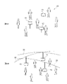
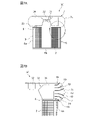
- FIG. 1 is a cross-sectional view showing the configuration of an air purifier according to the first embodiment of the present invention.
- FIG. 2 shows the configuration of the diffusion member of the air purifier according to the first embodiment
- FIG. 2A is an enlarged cross-sectional view of a hole in the diffusion member
- FIG. 2B is a partially enlarged view of the inner surface of the diffusion member.
- FIG. 3A is a cross-sectional view showing the configuration of the air purifier according to the second embodiment of the present invention
- FIG. 3B is a partially enlarged view of FIG. 3A.
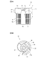
- FIG. 4A is a view of the inside of the housing of the air purifier according to the second embodiment as viewed from above, and FIG.
- FIG. 4B is a view showing a modified example of the support plate supporting the diffuser guide in the second embodiment.
- FIG. 5 is a cross-sectional view showing a modified example of the housing in the second embodiment.
- FIG. 6A is a diagram showing an air purifying system according to a third embodiment of the present invention, and FIG. 6B is a diagram showing a modified example of the air purifying system according to the third embodiment.
- FIG. 7A is a cross-sectional view showing the configuration of the air purifier according to the fourth embodiment of the present invention, and FIG. 7B is a partially enlarged view of FIG. 7A.
- FIG. 8 is a view of the inside of the diffusion member of the air purifier according to the fourth embodiment as viewed from above.
- FIG. 8 is a view of the inside of the diffusion member of the air purifier according to the fourth embodiment as viewed from above.
- FIG. 9A is a cross-sectional view showing the configuration of the air purifier according to the fifth embodiment of the present invention
- FIG. 9B is a view of the inside of the diffusion member of the air purifier according to the fifth embodiment as viewed from above
- FIG. 10A is a cross-sectional view showing the configuration of the air purifier according to the sixth embodiment of the present invention
- FIG. 10B is a view of the inside of the housing of the air purifier according to the sixth embodiment as viewed from above.
- the object of the present invention is mainly achieved by an air purifier having a function of purifying air close to the air purifier. This function is obtained by diffusing and blowing air from the air purifier outlet in a wide angle, and by bringing the air suction port closer to the outlet.
- An air purifier is a device that sucks in air, cleans the sucked air with a filter, and then blows it out.
- the amount of impurities removed by the filter is very small, and substantially the same amount of air as the sucked air is ejected from the air purifier.
- Simplifying the air blow and suction in the air purifier at one point each, the air flow outside the air purifier is modeled as a potential flow from the blow point to the suction point.
- the velocity at the radius position is inversely proportional to the cube of the radius. Decrease.
- the radius becomes smaller and becomes less than the distance between the blowing point and the suction point, it becomes a close field where a large speed is generated due to the influence of the positions of the blowing point and the suction point.
- the first design requirement is to reduce the area of the proximity field by making the suction port and the outlet as close as possible.
- the second design requirement is to prevent a jet from occurring at the blowout portion. When air blows out into a large space, it often becomes a jet that goes straight in a specific direction and reaches farther than the previous potential current. Air is blown out by spreading the flow at a wide angle to prevent the formation of a jet.
- FIG. 1 is a cross-sectional view showing the configuration of an air purifier according to the first embodiment of the present invention.
- the air purifier 1 shown in FIG. 1 includes a filter 2, a fan 3, a drive unit 4, a partition member 5, a housing 6 for accommodating these, and a diffusion member 7.
- the housing 6 has a cylindrical shape with one end closed, and is composed of a side wall 6a and a bottom wall 6b.
- a large number of microholes 8 penetrating the side wall 6a are formed on the side wall 6a over the entire surface of the side wall 6a, so that air outside the housing 6 can be sucked.
- the filter 2 has a cylindrical shape having a smaller diameter than the housing 6, and is arranged concentrically with the side wall 6a in the housing 6.
- the filter 2 is made of a porous material made by bundling glass fibers and the like, and purifies the air, that is, removes dust, pollen, viruses and the like in the air.
- the type and configuration of the filter 2 are not limited to this.
- the fan 3 sends out the air in the housing 6 upward, and is arranged near the upper end of the filter 2.
- the drive unit 4 includes a motor 10 that drives the fan 3 via the rotating shaft 9, and a power supply 11 that supplies electric power to the motor 10.
- the drive unit 4 is arranged inside the filter 2 in the housing 6, and the rotation shaft 9, the filter 2, and the side wall 6a of the fan 3 are concentric.
- the power supply 11 may be an outlet type or a battery type.
- the partition member 5 is an annular plate member that extends horizontally from the upper end of the filter 2 to the side wall 6a of the housing 6 and closes the space formed between the filter 2 and the side wall 6a from above.
- the partition member 5 can prevent the air that has passed through the filter 2 and the air that has not passed through the filter 2 from being mixed in the housing 6.
- the diffusion member 7 is made of a hollow hemispherical porous material.
- a large number of holes 12 are formed in the diffusion member 7 over the entire surface of the diffusion member 7.
- the hole 12 is a hexagonal through hole extending from the outer surface 7a of the diffusion member 7 toward the inner surface 7b, and is formed in the diffusion member 7. It is provided in a honeycomb shape.
- a porous resistor may be further provided on the inner side surface 7b of the diffusion member 7.
- the configuration of the diffusion member 7 is an example, and is not limited to this.
- the air around the air purifier 1 is sucked from the side wall 6a of the housing 6 by rotating the fan 3 by the drive unit 4.
- the filter 2 dust, pollen, viruses and the like are removed from this air, that is, it is purified.
- the purified air is sent upward by the fan 3, diffused through the diffusion member 7, and blown out to the outside of the air purifier 1.
- the air purifier 1 according to the present embodiment can purify the surrounding air.
- the side wall 6a of the housing 6 constitutes an air suction port
- the diffusion member 7 constitutes a clean air outlet
- the suction port and the blowout port are formed. Adjacent to the mouth. That is, the air purifier 1 satisfies the first design requirement that the suction port and the outlet are as close as possible to each other. Further, in the air purifier 1 according to the present embodiment, the purified air is blown out by the diffusion member 7 in a flux uniformed in the vertical direction of the curved surface of the diffusion member 7. Therefore, the second design requirement of preventing a jet flowing straight in a specific direction from being generated in the blowout portion is satisfied.
- the air purifier 1 according to the present embodiment causes a flow in which air circulates from the outlet to the suction port around the air purifier 1, that is, the air purifier.
- the air close to 1 can be purified.
- droplets and viruses generated from the infected person do not reach the person located on the leeward side of the infected person and infect the person. It is possible to effectively prevent the transmission of the virus to humans.
- the air purifier 1 when the air purifier 1 is arranged between two people, the air between the two people can be locally purified by the air purifier 1, that is, the two people sandwich the air purifier 1. Because it is separated by clean air, it can effectively prevent virus infection.
- FIG. 3A is a cross-sectional view showing the configuration of the air purifier according to the second embodiment of the present invention.
- the air purifier 15 shown in FIG. 3A the same components as those in the first embodiment are designated by the same reference numerals, the description thereof will be omitted, and different configurations will be described.
- the air purifier 15 according to the present embodiment has a filter 2, a support rod 13 of the filter 2, a housing 14 for accommodating the filter 2 and the support rod 13, a rotary shaft 9, a drive unit 4, and a housing. It consists of legs 16 that support 14.
- the housing 14 has a hollow flat spherical shape, and in detail, has a rounded rectangular shape having two sides (upper side and lower side) having the same length and two semicircles having a cross section along the central axis. ..
- a large number of micropores 8 penetrating the upper wall 14a and the lower wall 14b are formed in the central portion of the upper wall 14a and the lower wall 14b (upper surface and lower surface of the flat sphere) of the housing 14, and the outer surface of the housing 14 is formed. It is possible to inhale the air.
- a circular opening 17 for passing the rotating shaft 9 is also provided in the center of the lower wall 14b.
- the semi-circular portion 14c (side surface of the flat sphere) of the housing 14 has the same configuration as the diffusion member 7 of the first embodiment, and a large number of hexagonal holes 12 have a honeycomb shape over the entire surface of the semi-circular portion 14c. Is formed in.
- a cylindrical filter 2 is rotatably housed in such a housing 14.
- Ring-shaped plate-shaped members 18 and 18 having the same diameter as the filter 2 are attached to the upper and lower ends of the filter 2.
- the plate-shaped member 18 on the upper end side of the filter 2 is fixed to the rotating shaft 9 via four support rods 13, and the plate-shaped member 18 on the lower end side of the filter 2 is also fixed to this. Is similar to.
- the rotation shaft 9 is rotated by the drive unit 4, so that the filter 2 can be rotated integrally with the rotation shaft 9. Then, the centrifugal force generated by the rotation of the filter 2 can send the air in the housing 14 outward in the radial direction.
- the leg 16 is composed of four rod-shaped members extending downward from the lower wall 14b of the housing 14.
- the drive unit 4 is located at the center of these four rod-shaped members. Since the housing 14 is supported by the legs 16, the legs 16 do not hinder the air outside the housing 14 when it is sucked through the micropores 8 of the lower wall 14b of the housing 14.
- a diffuser guide 19 for adjusting the air flow in the housing 14 is provided in the housing 14 between the filter 2 and the semicircular portion 14c of the housing 14. .
- the diffuser guide 19 is composed of a plurality of plate-shaped annular members having different horizontal widths arranged at equal intervals in the vertical direction. Each plate-shaped annular member extends horizontally from the filter 2 toward the semicircular portion 14c of the housing 14, and its outer edge portion is inclined so as to be substantially perpendicular to the semicircular portion 14c.
- the diffuser guide 19 having such a configuration can uniformly guide the air cleaned by the filter 2 to the entire inner surface of the diffusion member 7.
- each plate-shaped annular member constituting the diffuser guide 19 is supported by four support plates 21 erected from the upper wall 14a to the lower wall 14b of the housing 14.
- the four support plates 21 are arranged at a predetermined angle from a direction perpendicular to the outer peripheral surface of the filter 2 when viewed from above. In other words, the four support plates 21 are diagonally arranged along the direction in which air is blown out from the filter 2.
- the air purifier 15 when the filter 2 is rotated by the drive unit 4, the air in the filter 2 rotates together with the filter 2 to generate centrifugal force, and the filter 2 has a centrifugal force. A radial outer air flow is generated from the inner surface to the outer surface. As a result, the air around the air purifier 15 is sucked from the upper wall 14a and the lower wall 14b of the housing 14. This air is purified by passing through the filter 2. Then, the purified air is guided by the diffuser guide 19 and reaches the semicircular portion 14c of the housing 14.
- the flow of the clean air blown out from the rotating filter 2 has a swirling component, but the flow rate of the air is adjusted by the diffuser guide 19 to evenly guide it to the semicircular portion 14c of the housing 14. Can be done. Then, the purified air that has reached the semicircular portion 14c is diffused through the semicircular portion 14c and blown out to the outside of the air purifier 15. In this way, the air purifier 15 according to the present embodiment can purify the surrounding air.
- the upper wall 14a and the lower wall 14b of the housing 14 form an air suction port, and the semicircular portion 14c constitutes a clean air outlet.
- the suction port and the outlet are adjacent to each other, satisfying the first design requirement.
- the purified air is blown out by the semicircular portion 14c in a flux uniformed in the vertical direction of the curved surface of the semicircular portion 14c, so that a second design requirement is also required. Is pleased.
- the air purifier 15 according to the present embodiment satisfies the first and second design requirements, and can exhibit the same effect as the air purifier 1 according to the first embodiment.
- the air purifier 15 according to the present embodiment has a configuration in which the filter 2 plays the role of a blower mechanism
- the air purifier 15 has a housing as compared with the air purifier 1 according to the first embodiment, which is provided with a fan 3 as a blower mechanism.
- the volume occupied by the air blowing mechanism in the body 14 can be reduced.
- ordinary air purifiers are designed so that the speed at which air passes through the filter is low in order to reduce pressure loss.
- the speed of the air can be kept low by directly guiding the purified air emitted from the side surface of the filter 2 to the semicircular portion 14c of the housing 14. Therefore, the first and second design requirements can be satisfactorily satisfied.
- the configuration of the support plate 21 that supports the diffuser guide 19 in the housing 14 is not limited to the above.
- the airfoil-shaped support plate 22 shown in FIG. 4B can be used instead of the support plate 21, the airfoil-shaped support plate 22 shown in FIG. 4B can be used.
- FIG. 4B is a diagram showing a modified example of the support plate 21 that supports the diffuser guide 19 in the housing 14 in the air purifier 15 according to the second embodiment.
- the support plate 22 shown in FIG. 4B is arranged so as to be inclined by a predetermined angle from a direction perpendicular to the outer peripheral surface of the filter 2 when viewed from above so as to be along the air blowing direction from the filter 2. ..
- the outer portion 22a of the support plate 22 when viewed from the rotation shaft 9 is bent outward in the radial direction and becomes thinner toward the outer tip. With such a shape, the support plate 22 can guide the air blown out from the rotating filter 2 and remove the swirling component contained in the air.
- the inner portion 22b of the support plate 22 when viewed from the rotating shaft 9 has a blunt head shape.
- the air volume of the air blown out from the filter 2 increases or decreases, and the blowing direction of the air from the filter 2 also changes. Even if the direction of air blown out from the filter 2 changes, the blunt head shape of the inner portion 22b of the support plate 22 causes air separation at the inner portion 22b and obstructs the air flow. Can be effectively prevented.
- the configuration of the housing 14 is not limited to the above.
- the housing 23 shown in FIG. 5 can be used instead of the housing 14.
- FIG. 5 is a diagram showing a modified example of the housing 14 in the air purifier 15 according to the second embodiment.
- the housing 23 shown in FIG. 5 is the above-mentioned housing 14 in which the radius of the circular lower wall 14b is larger than the radius of the circular upper wall 14a, which is concentric with the upper wall 14a.
- the shape is composed of an upper side and a lower side having parallel cross sections along the central axis of the housing 23 and two substantially semicircles connecting them, and the lower side is longer than the upper side.
- the lower wall 14b is not formed with the fine holes 8, and it is possible to suck the air outside the housing 23 only through the large number of fine holes 8 on the upper wall 14a.
- a diffuser guide 19 (not shown) is also provided in the housing 6.
- the clean air blown out from the upper part of the semicircular portion 14c circulates in a small circle and is blown out from the lower part of the semicircular portion 14c. Since the cleaned air can be circulated in a large circle, the air around the air purifier 15, particularly above, can be effectively cleaned.
- FIG. 6A is a diagram showing an air purifying system according to a third embodiment of the present invention.
- the air purifying system 25 comprises a plurality of air purifiers 15 according to the second embodiment, which can locally purify the air around the air purifier, placed on the floor.
- the air between the people can be locally purified, so that the person and the person can clean the air purifier 15 It is separated by clean air.
- the conventional air purifier that cleans a wide area of the room often cleans the ceiling and the corners of the room where there are no people
- the air purifying system 25 of this embodiment focuses on the space where people gather.
- the flow path of the blowout is expanded to increase the cross-sectional area of the flow path, and a large volume to be cleaned can be secured in the space where people gather, so that it is possible to efficiently reduce the transmission of virus from person to person. can.
- the air purifier 1 according to the first embodiment and the air purifier 30 according to the fourth to sixth embodiments described later are used.
- FIG. 6B is a diagram showing a modified example of the air purifying system 25 according to the third embodiment.
- a holding member 26 for suspending and holding the air purifier 15 is provided above the space where people gather, and a plurality of air purifiers 15 are suspended and arranged on the holding member 26. Also, this can produce the same effect as the above-mentioned floor-standing arrangement.
- FIG. 7A is a cross-sectional view showing the configuration of the air purifier according to the fourth embodiment of the present invention.
- the air purifier 30 shown in FIG. 7A the same components as those of the first and second embodiments are designated by the same reference numerals, the description thereof will be omitted, and different configurations will be described.
- the air purifier 30 includes a filter 2, a centrifugal fan 31 arranged above the filter 2, a drive unit 32 for driving the centrifugal fan 31, a partition member 5, a housing 6 for accommodating these, and a housing 6. It is composed of a diffusion member 7.
- the air purifier 1 according to the first embodiment uses an axial fan 3.
- a centrifugal type centrifugal fan 31 which is advantageous for increasing the flow rate of air and reducing noise is adopted.
- the centrifugal fan 31 generates centrifugal force by rotating the air between the blades 31a by rotating an annular rotating body having a plurality of blades 31a (see FIG. 8) arranged along the rotation direction. It induces the flow of air from the inside to the outside of the rotating body.
- a gap 33 is provided between the centrifugal fan 31 and the partition member 5 so that the rotating centrifugal fan 31 does not come into contact with the partition member 5.
- the drive unit 32 includes a motor for driving the centrifugal fan 31 and a power source for supplying electric power to the motor.
- the drive unit 32 is arranged above the centrifugal fan 31, and the center of rotation of the centrifugal fan 31, the filter 2, and the side wall 6a are concentric.
- the diffusion member 7 has a hollow flat spherical shape like the housing 14 in the second embodiment. Unlike the second embodiment, the upper surface of the diffusion member 7 is closed by an upper wall 34 that does not allow air to pass through, and a drive unit 32 is fixed to the inner surface of the upper wall 34. The lower surface of the diffusion member 7 is open and attached to the upper end of the housing 6.
- a diffuser guide 19 similar to that of the second embodiment is provided between the centrifugal fan 31 and the semicircular portion 7c of the diffusion member 7 in the diffusion member 7. As shown in FIG. 8, the diffuser guide 19 is supported by the airfoil-shaped support plate 22 shown in FIG. 4B described above as a modification of the second embodiment.
- the air around the air purifier 30 is sucked from the side wall 6a of the housing 6 by rotating the centrifugal fan 31 by the drive unit 32.
- This air is purified by passing through the filter 2.
- the purified air hereinafter, also referred to as “clean air”
- This clean air is guided upward by the centrifugal fan 31 and sent out from the inside to the outside of the centrifugal fan 31, that is, outward in the radial direction.
- This clean air is guided by the diffuser guide 19 and reaches the semicircular portion 7c of the diffusion member 7.
- the diffuser guide 19 uniformly decelerates the air flow while effectively removing the swirling component by the support plate 22. It can be guided to the semi-circular portion 7c of the diffusion member 7. Then, the clean air that has reached the semicircular portion 7c is diffused through the semicircular portion 7c and blown out to the outside of the air purifier 30. In this way, the air purifier 30 according to the present embodiment can purify the surrounding air.
- the side wall 6a of the housing 6 constitutes an air suction port
- the semicircular portion 7c of the diffusion member 7 constitutes a clean air outlet.
- the suction port and the outlet are adjacent to each other, satisfying the first design requirement.
- the purified air is blown out by the semicircular portion 7c in a flux uniformed in the vertical direction of the curved surface of the semicircular portion 7c, so that the second design requirement is also satisfied. Is pleased.
- the air purifier 30 according to the present embodiment satisfies the first and second design requirements, and can exhibit the same effect as the air purifier 1 according to the first embodiment.
- the air purifier 30 according to the present embodiment employs a centrifugal fan 31 as a blowing mechanism, so that the air purifier 30 has an air flow type fan 3 as compared with the air purifier 1 according to the first embodiment. It is possible to increase the flow rate, that is, improve the cleaning capacity and reduce the noise.
- FIG. 9A is a cross-sectional view showing the configuration of the air purifier according to the fifth embodiment of the present invention.
- the air purifier 35 shown in FIG. 9A the same components as those in the fourth embodiment are designated by the same reference numerals, the description thereof will be omitted, and different configurations will be described.
- the air purifier 35 includes a diffuser guide 36 and a shell (guide member) 37 in place of the diffuser guide 19 in the air purifier 30 according to the fourth embodiment.
- the diffuser guide 36 views each plate-shaped annular member constituting the diffuser guide 19 at the same position when viewed from above, specifically, the second and third support plates 22 from the vicinity of the rear side of any support plate 22. In more detail, it consists of a C-shaped cutout of about 135 degrees from the center.
- the shell 37 is formed by bending a U-shaped plate-shaped member having a gentle cross section into a shell shape.
- the shell 37 is arranged in a notched portion of each plate-shaped annular member constituting the diffuser guide 36 so as to cover the portion.
- one end of the shell 37 is arranged near the inner end of any of the above-mentioned support plates 22, and the other end of the shell 37 is arranged near the outer end of each plate-shaped annular member. Has been done.
- the air purifier 35 according to the present embodiment can exert the same effect as the air purifier 30 according to the fourth embodiment.
- the clean air traveling toward the shell 37 is guided by the shell 37 in the rotational direction of the centrifugal fan 31 to guide the diffuser. 36, more specifically, guided to the notched end of each plate-shaped annular member.
- the clean air is guided by each plate-shaped annular member, diffused through the semicircular portion 7c of the diffusion member 7, and blown out to the outside of the air purifier 35.
- the air purifier 35 can guide the clean air traveling toward the shell 37 to the diffuser guide 19 and blow it out to the outside of the air purifier 35 without loss.
- the air purifier 35 when used by arranging it near a wall or the backrest of a chair, for example, by arranging the wall or the backrest of the chair to be located on the back side of the shell 37, the clean air can be made into a wall. It is possible to effectively prevent the virus from spreading in an unintended direction due to collision with the backrest of a chair or a chair.
- FIG. 10A is a cross-sectional view showing the configuration of the air purifier according to the sixth embodiment of the present invention.
- the same components as those in the second and fifth embodiments are designated by the same reference numerals, the description thereof will be omitted, and different configurations will be described.
- the diffuser guide 36, the shell 37, and the support plate 22 described in the fifth embodiment are applied to the air purifier according to the modified example of the second embodiment shown in FIG. Is.
- the air purifier 40 according to the present embodiment can exert the same effect as the air purifier 15 according to the second embodiment.
- the air purifier 40 according to the present embodiment when the air purifier 40 according to the present embodiment is arranged and used near, for example, a wall or the backrest of a chair, clean air is generated on the wall or the like. It is possible to effectively prevent the virus from spreading as a result of an air flow occurring in an unintended direction due to a collision with the backrest of a chair or the like.
- Air purifier 2 Filter 3 Fan 4, 32 Drive unit 6, 14, 23 Housing 7 Diffuser 8 Microhole 9 Rotating shaft 10 Motor 11 Power supply 12 Hole 13 Support rod 16 Leg 18 Plate Shape member 19, 36 Diffuser guide 21, 22 Support plate 25 Air purification system 31 Centrifugal fan 31a Centrifugal fan blade 37 Shell
Abstract
空気清浄機は、外部の空気を吸い込むための吸い込み口が設けられた筐体(6)と、筐体(6)に収納されており、空気を清浄するためのフィルター(2)と、筐体(6)に収納されており、空気を送り出すための送風部材(3)と、送風部材(3)を回転駆動するための駆動部(4)と、フィルター(2)によって清浄された空気を外部へ吹き出すための吹き出し口として筐体(6)に備えられた拡散部材(7)とを有し、前記吸い込み口と前記吹き出し口とが隣り合っており、フィルター(2)で清浄された空気が拡散部材(7)によって拡散して吹き出される。これにより、人から人へのウイルスの感染防止に好適な空気清浄機等を提供することができる。
Description
本発明は、空気清浄機、空気清浄方法、空気清浄システムに関する。
空気清浄機は、空気中に漂う埃、花粉、ウイルス等を除去して清浄な空気を供給する装置であり、吸い込んだ空気をフィルターに通して清浄な空気を吹き出すタイプや、清浄効果を高めるために清浄された空気にイオンを添加するタイプが知られている。
一般に空気清浄機の技術課題は、空気清浄機1台で広範囲な空間を清浄することとされている。特許文献1には、広範囲の汚染空気を吸い込むことに適した構造が開示されている。特許文献2には、清浄された空気を広範囲に送出できる構造が開示されている。非特許文献1には、空気の吹き出しと吸い込みによって室内全体を空気が循環する流れを作り、遠方の埃を除去する概念が示されている。
SHARP空気清浄機パンフレット(KC-J50/FU-J50/FU-J30)
2020年、新型コロナウイルスの感染拡大が世界的な社会問題となった。感染症の流行は100年前のペストを代表に何度も発生しており、世界がグローバル化し人と物が行き交う現代において感染症の流行のリスクは年々高まっている。新型コロナウイルスはインフルエンザウイルスと同様に人のくしゃみ等で生じた飛沫を媒介に感染するとされている。微細な飛沫は空気の流れに乗って移流するため、空気を清浄に保つことが感染防止に有効となる。このため、空気中に漂う飛沫やウイルスを効果的に除去する空気清浄機が求められる。
上述のように従来の空気清浄機は、総じて室内の広範囲を清浄することに適しており、空気清浄機で清浄された空気は勢いよく吹き出されて遠方まで達する。空気清浄機から吹き出された空気は室内の空気を巻き込みながら再び空気清浄機に戻ることにより、飛沫やウイルスが除去されて室内の空気は広範囲にわたって清浄される。
しかしながら、室内の広範囲を清浄する従来の空気清浄機においては、室内に複数の人が集まる場合に感染者から発生した飛沫やウイルスが感染者の風下に位置する人に達して感染させてしまうおそれがある。即ち、従来の空気清浄機は人から人へのウイルスの感染を防止することに適していないという問題があった。
そこで本発明は上記問題点に鑑みてなされたものであり、人から人へのウイルスの感染防止に好適な空気清浄機、空気清浄方法、空気清浄システムを提供することを目的とする。
上記課題を解決するために本発明は、
外部の空気を吸い込むための吸い込み口が設けられた筐体と、
前記筐体に収納されており、空気を清浄するためのフィルターと、
前記筐体に収納されており、空気を送り出すための送風部材と、
前記送風部材を回転駆動するための駆動部と、
前記フィルターによって清浄された空気を外部へ吹き出すための吹き出し口として前記筐体に備えられた拡散部材とを有し、
前記吸い込み口と前記吹き出し口とが隣り合っており、前記フィルターで清浄された空気が前記拡散部材によって拡散して吹き出されることを特徴とする空気清浄機を提供する。
外部の空気を吸い込むための吸い込み口が設けられた筐体と、
前記筐体に収納されており、空気を清浄するためのフィルターと、
前記筐体に収納されており、空気を送り出すための送風部材と、
前記送風部材を回転駆動するための駆動部と、
前記フィルターによって清浄された空気を外部へ吹き出すための吹き出し口として前記筐体に備えられた拡散部材とを有し、
前記吸い込み口と前記吹き出し口とが隣り合っており、前記フィルターで清浄された空気が前記拡散部材によって拡散して吹き出されることを特徴とする空気清浄機を提供する。
また本発明は、
上記空気清浄機を人と人の間に配置することを特徴とする空気清浄方法を提供する。
また本発明は、
上記空気清浄機を複数台分散配置したことを特徴とする空気清浄システムを提供する。
また本発明は、
周辺の空気を局所的に清浄する空気清浄機を複数台分散配置したことを特徴とする空気清浄システムを提供する。
上記空気清浄機を人と人の間に配置することを特徴とする空気清浄方法を提供する。
また本発明は、
上記空気清浄機を複数台分散配置したことを特徴とする空気清浄システムを提供する。
また本発明は、
周辺の空気を局所的に清浄する空気清浄機を複数台分散配置したことを特徴とする空気清浄システムを提供する。
本発明によれば、人から人へのウイルスの感染防止に好適な空気清浄機、空気清浄方法、空気清浄システムを提供することができる。
本発明の目的は、主として空気清浄機に近接する空気を清浄する機能を有する空気清浄機によって達成される。この機能は空気清浄機の吹き出し口から空気を広角に拡散させて吹き出すこと、及び空気の吸い込み口を吹き出し口に近づけることで得られる。
斯かる機能を有する空気清浄機の概念的な設計要件を詳しく説明する。空気清浄機は空気を吸い込み、吸い込んだ空気をフィルターで清浄後、吹き出す装置である。フィルターによって除去される不純物は微量であり、吸い込まれる空気と実質的に等量の空気が空気清浄機から噴出される。空気清浄機における空気の吹き出し及び吸い込みをそれぞれ1つの点で単純化すると、空気清浄機の外部の空気の流れは吹き出し点から吸い込み点に向かうポテンシャル流でモデル化される。このポテンシャル流では吹き出し点と吸い込み点の間の距離に比べて動径(2点の重心点からの距離)が十分大きくなると、動径位置での速度は動径の3乗に逆比例して減少する。動径が小さくなり概ね吹き出し点と吸い込み点の間の距離以下となると吹き出し点、吸い込み点それぞれの位置の影響を受け大きな速度が生じる近接場となる。ある有限の部屋を想定したとき、吸い込み口と吹き出し口を極力近づけて近接場の領域を減らすことが第1の設計要件となる。第2の設計要件は吹き出し部で噴流が生じることを防止することである。空気が広い空間に吹き出すとき、往々にして特定の方向に直進する噴流となって先のポテンシャル流よりも遠方に到達する。噴流が生じることを防止するために流れを広角に拡散させて空気を吹き出す。
本発明の各実施形態に係る空気清浄機を添付図面に基づいて説明する。
(第1実施形態)
図1は本発明の第1実施形態に係る空気清浄機の構成を示す断面図である。
図1に示す空気清浄機1は、フィルター2、ファン3、駆動部4、仕切り部材5、これらを収納する筐体6、及び拡散部材7からなる。
(第1実施形態)
図1は本発明の第1実施形態に係る空気清浄機の構成を示す断面図である。
図1に示す空気清浄機1は、フィルター2、ファン3、駆動部4、仕切り部材5、これらを収納する筐体6、及び拡散部材7からなる。
筐体6は、一端が閉塞された円筒形状をしており、側壁6aと底壁6bとからなる。側壁6aには、側壁6aを貫通する多数の微孔8が側壁6aの全面にわたって形成されており、筐体6外部の空気を吸い込むことが可能になっている。
フィルター2は、筐体6よりも小径の円筒形状をしており、筐体6内に側壁6aと同心円状に配置されている。フィルター2は、ガラス繊維等を束ねてなる多孔質材からなり、空気を清浄する、即ち空気中の埃、花粉、ウイルス等を除去するものである。なお、フィルター2の種類や構成はこれに限られるものではない。
ファン3は、筐体6内の空気を上方へ送り出すものであり、フィルター2の上端付近に配置されている。
駆動部4は、ファン3を回転軸9を介して駆動するモーター10、モーター10に電力を供給する電源11からなる。駆動部4は筐体6内のフィルター2の内側に配置されており、ファン3の回転軸9、フィルター2、側壁6aが同心となっている。なお、電源11はコンセント式でもバッテリー式でもよい。
仕切り部材5は、フィルター2の上端から筐体6の側壁6aへ水平に延在してフィルター2と側壁6aの間に形成された空間を上方から閉塞するための円環状の板部材からなる。仕切り部材5により、フィルター2を通過した空気とフィルター2を通過していない空気とが筐体6内で混ざり合ってしまうことを防ぐことができる。
拡散部材7は、中空の半球形状をした多孔質材からなる。拡散部材7には、多数の孔12が拡散部材7の全面にわたって形成されている。孔12は、図2(a)及び図2(b)に示すように拡散部材7の外側面7aから内側面7bへ向かって先細りするように延びる六角形状の貫通孔であり、拡散部材7に蜂の巣状に設けられている。斯かる構成の拡散部材7により、ファン3で送り出された筐体6内の空気を拡散部材7の曲面の垂直方向へ均一化した流束で吹き出すことができる。なお、この効果をより高めるために拡散部材7の内側面7bに多孔質の抵抗体をさらに設けてもよい。また、斯かる拡散部材7の構成は一例を示したものであり、これに限られるものではない。
以上の構成の下、本実施形態に係る空気清浄機1は、駆動部4によってファン3が回転することにより、空気清浄機1周辺の空気が筐体6の側壁6aから吸い込まれる。この空気はフィルター2を通過することで埃、花粉、ウイルス等が除去、即ち清浄される。そして清浄された空気はファン3によって上方へ送り出され、拡散部材7を介して拡散されて空気清浄機1の外部へ吹き出される。このようにして本実施形態に係る空気清浄機1は周囲の空気を清浄することができる。
ここで、本実施形態に係る空気清浄機1では、筐体6の側壁6aが空気の吸い込み口を構成し、拡散部材7が清浄された空気の吹き出し口を構成しており、吸い込み口と吹き出し口とが隣接している。即ち、空気清浄機1は先に述べた吸い込み口と吹き出し口を極力近づけるという第1の設計要件を満足している。
また、本実施形態に係る空気清浄機1では、清浄された空気は拡散部材7によって拡散部材7の曲面の垂直方向へ均一化した流束で吹き出される。したがって、吹き出し部で特定方向に直進する噴流が生じることを防止するという第2の設計要件を満足している。
また、本実施形態に係る空気清浄機1では、清浄された空気は拡散部材7によって拡散部材7の曲面の垂直方向へ均一化した流束で吹き出される。したがって、吹き出し部で特定方向に直進する噴流が生じることを防止するという第2の設計要件を満足している。
本実施形態に係る空気清浄機1は、第1及び第2の設計要件を満足することにより、空気清浄機1の周辺において空気が吹き出し口から吸い込み口へ循環する流れが生じ、即ち空気清浄機1に近接する空気を清浄することができる。これにより本実施形態に係る空気清浄機1は、従来の空気清浄機のように感染者から発生した飛沫やウイルスが感染者の風下に位置する人に達して感染させてしまうことがなく、人から人へのウイルスの感染を効果的に防止することができる。具体的には、例えば2人の人の間に空気清浄機1を配置した場合、2人の間の空気を空気清浄機1で局所的に清浄でき、即ち2人は空気清浄機1を挟んで清浄された空気で隔てられるため、ウイルスの感染を効果的に防止することができる。
(第2実施形態)
図3Aは本発明の第2実施形態に係る空気清浄機の構成を示す断面図である。
図3Aに示す空気清浄機15について、上記第1実施形態と同様の構成については同じ符号を付して説明を省略し、異なる構成について説明する。
図3Aに示すように本実施形態に係る空気清浄機15は、フィルター2、フィルター2の支持棒13、フィルター2と支持棒13を収納する筐体14、回転軸9、駆動部4、筐体14を支持する脚16からなる。
図3Aは本発明の第2実施形態に係る空気清浄機の構成を示す断面図である。
図3Aに示す空気清浄機15について、上記第1実施形態と同様の構成については同じ符号を付して説明を省略し、異なる構成について説明する。
図3Aに示すように本実施形態に係る空気清浄機15は、フィルター2、フィルター2の支持棒13、フィルター2と支持棒13を収納する筐体14、回転軸9、駆動部4、筐体14を支持する脚16からなる。
筐体14は、中空の扁平球状をしており、詳細には中心軸に沿った断面が長さの等しい2辺(上辺及び下辺)と2つの半円形からなる角丸長方形状をしている。
筐体14の上壁14a及び下壁14b(扁平球の上面及び下面)の中央部分には、上壁14a及び下壁14bを貫通する多数の微孔8が形成されており、筐体14外部の空気を吸い込むことが可能になっている。なお、下壁14bの中心部には、回転軸9を通すための円形開口17も設けられている。
筐体14の半円形部分14c(扁平球の側面)は上記第1実施形態の拡散部材7と同様の構成になっており、六角形状の多数の孔12が半円形部分14cの全面にわたって蜂の巣状に形成されている。
斯かる筐体14には円筒状のフィルター2が回転可能に収納されている。
筐体14の上壁14a及び下壁14b(扁平球の上面及び下面)の中央部分には、上壁14a及び下壁14bを貫通する多数の微孔8が形成されており、筐体14外部の空気を吸い込むことが可能になっている。なお、下壁14bの中心部には、回転軸9を通すための円形開口17も設けられている。
筐体14の半円形部分14c(扁平球の側面)は上記第1実施形態の拡散部材7と同様の構成になっており、六角形状の多数の孔12が半円形部分14cの全面にわたって蜂の巣状に形成されている。
斯かる筐体14には円筒状のフィルター2が回転可能に収納されている。
フィルター2の上端及び下端には、フィルター2と同径なリング状の板状部材18、18が取り付けられている。図3A及び図4Aに示すようにフィルター2の上端側の板状部材18は4本の支持棒13を介して回転軸9に固定されており、フィルター2の下端側の板状部材18もこれと同様である。この構成により、駆動部4によって回転軸9が回転することにより、回転軸9と一体的にフィルター2を回転させることができる。そしてフィルター2の回転によって生じる遠心力により、筐体14内の空気を径方向外側へ向かって送り出すことができる。
脚16は、筐体14の下壁14bから下方へ向かって延びた4本の棒状部材からなる。駆動部4はこの4本の棒状部材の中心に位置している。脚16で筐体14を支持する構成としたことにより、筐体14外部の空気が筐体14の下壁14bの微孔8から吸い込まれる際にこれを脚16が妨げることがない。
図3Bに示すように筐体14内には、フィルター2と筐体14の半円形部分14cとの間に、筐体14内の空気の流れを調節するためのディフューザーガイド19が備えられている。ディフューザーガイド19は、上下方向において等間隔に配置された水平方向幅の異なる複数の板状円環部材からなる。各板状円環部材は、フィルター2から筐体14の半円形部分14cへ向かって水平に延び、半円形部分14cと略垂直をなすように外側縁部が傾斜している。斯かる構成のディフューザーガイド19により、フィルター2で清浄された空気を拡散部材7の内側面全体へ均一に導くことができる。
図4Aに示すようにディフューザーガイド19を構成する各板状円環部材は、筐体14の上壁14aから下壁14bへ架設された4枚の支持板21によって支持されている。4枚の支持板21は、上方から見てフィルター2の外周面に垂直な方向から所定角度傾けて配置されている。言い換えれば、4枚の支持板21はフィルター2からの空気の吹き出し方向に沿うように斜めに配置されている。
以上の構成の下、本実施形態に係る空気清浄機15では、駆動部4によってフィルター2を回転させると、フィルター2内の空気がフィルター2とともに回転することで遠心力が発生し、フィルター2の内側面から外側面に向かう径方向外側の空気の流れが生じる。これにより、空気清浄機15周辺の空気は筐体14の上壁14a及び下壁14bから吸い込まれる。この空気はフィルター2を通過することで清浄される。そして清浄された空気は、ディフューザーガイド19で案内されて筐体14の半円形部分14cへ達する。このとき、回転するフィルター2から吹き出された清浄された空気の流れは旋回成分を持っているが、ディフューザーガイド19によって空気の流量を調節して筐体14の半円形部分14cへ均等に導くことができる。そして、半円形部分14cへ達した清浄された空気は、半円形部分14cを介して拡散されて空気清浄機15の外部へ吹き出される。このようにして本実施形態に係る空気清浄機15は周囲の空気を清浄することができる。
ここで、本実施形態に係る空気清浄機15では、筐体14の上壁14a及び下壁14bが空気の吸い込み口を構成し、半円形部分14cが清浄された空気の吹き出し口を構成しており、吸い込み口と吹き出し口とが隣接しており、第1の設計要件を満足している。
また、本実施形態に係る空気清浄機15では、清浄された空気は半円形部分14cによって半円形部分14cの曲面の垂直方向へ均一化した流束で吹き出されるため、第2の設計要件も満足している。
また、本実施形態に係る空気清浄機15では、清浄された空気は半円形部分14cによって半円形部分14cの曲面の垂直方向へ均一化した流束で吹き出されるため、第2の設計要件も満足している。
本実施形態に係る空気清浄機15は、第1及び第2の設計要件を満足しており、上記第1実施形態に係る空気清浄機1と同様の効果を奏することができる。
特に、本実施形態に係る空気清浄機15は、フィルター2が送風機構の役割を果たす構成であるため、送風機構としてファン3を備える上記第1実施形態に係る空気清浄機1に比して筐体14内で送風機構が占める体積を減らすことができる。さらに、通常の空気清浄機では、圧力損失を低減するために空気がフィルターを通過する速度が小さいように設計される。本実施形態に係る空気清浄機15では、フィルター2の側面から出た清浄された空気を筐体14の半円形部分14cへ直接的に導くことにより、空気の速度が小さく維持することができる。したがって、第1及び第2の設計要件を良好に満足することができる。
特に、本実施形態に係る空気清浄機15は、フィルター2が送風機構の役割を果たす構成であるため、送風機構としてファン3を備える上記第1実施形態に係る空気清浄機1に比して筐体14内で送風機構が占める体積を減らすことができる。さらに、通常の空気清浄機では、圧力損失を低減するために空気がフィルターを通過する速度が小さいように設計される。本実施形態に係る空気清浄機15では、フィルター2の側面から出た清浄された空気を筐体14の半円形部分14cへ直接的に導くことにより、空気の速度が小さく維持することができる。したがって、第1及び第2の設計要件を良好に満足することができる。
なお、本実施形態に係る空気清浄機15において、筐体14内でディフューザーガイド19を支持する支持板21の構成は上述のものに限られない。例えば支持板21の代わりに図4Bに示す翼型の支持板22を用いることもできる。図4Bは第2実施形態に係る空気清浄機15において筐体14内でディフューザーガイド19を支持する支持板21の変形例を示す図である。
図4Bに示す支持板22は、支持板21と同様、フィルター2からの空気の吹き出し方向に沿うように、上方から見てフィルター2の外周面に垂直な方向から所定角度傾けて配置されている。そして回転軸9から見て支持板22の外側部分22aは、径方向外側へ向かって屈曲しているとともに外側先端へ向かって厚みが薄くなっている。斯かる形状により支持板22は、回転するフィルター2から吹き出された空気を案内して当該空気に含まれている旋回成分を除去することができる。
また、回転軸9から見て支持板22の内側部分22bは鈍頭形状をしている。本実施形態に係る空気清浄機15においてフィルター2の回転数を変えることにより、フィルター2から吹き出される空気の風量が増減し、またフィルター2からの空気の吹き出し方向も変化する。フィルター2からの空気の吹き出し方向が変化した場合でも、支持板22の内側部分22bを鈍頭形状としたことにより、当該内側部分22bにおいて空気の剥離が生じて空気の流れを阻害してしまうことを効果的に防止することができる。
なお、本実施形態に係る空気清浄機15において、筐体14の構成は上述のものに限られない。例えば筐体14の代わりに図5に示す筐体23を用いることもできる。図5は第2実施形態に係る空気清浄機15における筐体14の変形例を示す図である。
図5に示す筐体23は、上述の筐体14において円形の上壁14aの半径よりも上壁14aと同心で円形の下壁14bの半径を大きくしたものである。詳しくは、筐体23の中心軸に沿った断面が平行な上辺及び下辺とこれらを接続する2つの略半円形とからなる形状であり、かつ上辺よりも下辺が長くなっている。また、下壁14bには微孔8が形成されておらず、上壁14aの多数の微孔8のみから筐体23外部の空気を吸い込むことが可能である。なお、筐体6内には不図示のディフューザーガイド19も備えられている。
斯かる構成の筐体23を用いることにより、図5に示すように半円形部分14cの上部から吹き出された清浄された空気は小さな円を描いて循環し、半円形部分14cの下部から吹き出された清浄された空気は大きな円を描いて循環することができるため、空気清浄機15の周囲、特に上方の空気を効果的に清浄することができる。
(第3実施形態)
図6Aは本発明の第3実施形態に係る空気清浄システムを示す図である。
図6Aに示すように空気清浄システム25は、空気清浄機周辺の空気を局所的に清浄可能な上記第2実施形態に係る空気清浄機15を複数台床置き配置してなる。人が集まる空間において複数台の空気清浄機15を複数の人の間に分散して配置することにより、人と人の間の空気を局所的に清浄できるため、人と人は空気清浄機15を挟んで清浄された空気で隔てられる。これにより、室内全体へ及ぶ空気の循環流の発生を避けることができるため、感染者の下流に位置する人へのウイルスの感染が生じにくい。言い換えれば、室内の広い範囲を清浄する従来の空気清浄機は往々にして人のいない天井や部屋の隅まで清浄するのに対し、本実施形態の空気清浄システム25は人が集まる空間に絞って清浄することができる。空気清浄機15は吹き出しの流路が拡大されて流路断面積が増え、人が集まる空間で清浄される体積を大きく確保できるため、人から人へのウイルスの感染を効率良く低減することができる。
なお、本実施形態に係る空気清浄システム25では、複数台の空気清浄機15に代えて上記第1実施形態に係る空気清浄機1、後述する第4~6実施形態に係る空気清浄機30、35、40を複数台用いることも勿論可能である。
また、本実施形態に係る空気清浄システム25において、複数台の空気清浄機15の配置は床置きに限られない。図6Bは第3実施形態に係る空気清浄システム25の変形例を示す図である。図6Bに示すように、人が集まる空間の上方に空気清浄機15を吊り下げ保持するための保持部材26を設け、この保持部材26に複数台の空気清浄機15を吊り下げ配置する構成としてもよく、これにより上述の床置き配置と同様の効果を奏することができる。
(第4実施形態)
図7Aは本発明の第4実施形態に係る空気清浄機の構成を示す断面図である。
図7Aに示す空気清浄機30について、上記第1、第2実施形態と同様の構成については同じ符号を付して説明を省略し、異なる構成について説明する。
図7Aに示すように空気清浄機30は、フィルター2、フィルター2の上方に配置された遠心ファン31、遠心ファン31を駆動する駆動部32、仕切り部材5、これらを収納する筐体6、及び拡散部材7からなる。
図7Aは本発明の第4実施形態に係る空気清浄機の構成を示す断面図である。
図7Aに示す空気清浄機30について、上記第1、第2実施形態と同様の構成については同じ符号を付して説明を省略し、異なる構成について説明する。
図7Aに示すように空気清浄機30は、フィルター2、フィルター2の上方に配置された遠心ファン31、遠心ファン31を駆動する駆動部32、仕切り部材5、これらを収納する筐体6、及び拡散部材7からなる。
上記第1実施形態に係る空気清浄機1では軸流型のファン3を採用している。これに対して本実施形態に係る空気清浄機30では、空気の大流量化と低騒音化に有利な遠心型の遠心ファン31を採用している。遠心ファン31は、回転方向に沿って配置された複数枚の羽根31a(図8を参照)を備えた環状の回転体が回転することにより、羽根31a間の空気を連れ回して遠心力を発生させ、回転体の内側から外側へ向かう空気の流れを誘起するものである。なお、遠心ファン31と仕切り部材5の間には、回転する遠心ファン31が仕切り部材5に接触しないように間隙33が設けられている。
駆動部32は、上記第1実施形態における駆動部4と同様、遠心ファン31を駆動するモーター、該モーターに電力を供給する電源からなる。駆動部32は遠心ファン31の上部に配置されており、遠心ファン31の回転中心、フィルター2、側壁6aが同心となっている。
拡散部材7は、上記第2実施形態における筐体14と同様、中空の扁平球形状をしている。拡散部材7の上面は、第2実施形態と異なり空気を通さない上壁34によって閉塞され、上壁34の内側面には駆動部32が固定されている。なお、拡散部材7の下面は開放されており、筐体6の上端に取り付けられている。
図7Bに示すように拡散部材7内には、遠心ファン31と拡散部材7の半円形部分7cとの間に、第2実施形態と同様のディフューザーガイド19が備えられている。図8に示すようにディフューザーガイド19は、第2実施形態の変形例として上述した図4Bに示す翼型の支持板22によって支持されている。
以上の構成の下、本実施形態に係る空気清浄機30は、駆動部32によって遠心ファン31が回転することにより、空気清浄機30周辺の空気が筐体6の側壁6aから吸い込まれる。この空気はフィルター2を通過することで清浄される。そして清浄された空気(以下「清浄空気」ともいう)は遠心ファン31によって上方へ導かれ、遠心ファン31の内側から外側、即ち径方向外側へ送り出される。この清浄空気は、ディフューザーガイド19で案内され、拡散部材7の半円形部分7cへ達する。なお、回転する遠心ファン31から送り出された清浄空気の流れは旋回成分を持っているが、支持板22により効果的に旋回成分を除去しつつ、ディフューザーガイド19によって空気の流れを均一に減速し拡散部材7の半円形部分7cへ導くことができる。そして、半円形部分7cへ達した清浄空気は、半円形部分7cを介して拡散されて空気清浄機30の外部へ吹き出される。このようにして本実施形態に係る空気清浄機30は周囲の空気を清浄することができる。
ここで、本実施形態に係る空気清浄機30では、筐体6の側壁6aが空気の吸い込み口を構成し、拡散部材7の半円形部分7cが清浄された空気の吹き出し口を構成しており、吸い込み口と吹き出し口とが隣接しており、第1の設計要件を満足している。
また、本実施形態に係る空気清浄機30では、清浄された空気は半円形部分7cによって半円形部分7cの曲面の垂直方向へ均一化した流束で吹き出されるため、第2の設計要件も満足している。
また、本実施形態に係る空気清浄機30では、清浄された空気は半円形部分7cによって半円形部分7cの曲面の垂直方向へ均一化した流束で吹き出されるため、第2の設計要件も満足している。
本実施形態に係る空気清浄機30は、第1及び第2の設計要件を満足しており、上記第1実施形態に係る空気清浄機1と同様の効果を奏することができる。
特に、本実施形態に係る空気清浄機30は、送風機構として遠心ファン31を採用したことにより、軸流型のファン3を備える上記第1実施形態に係る空気清浄機1に比して、空気の大流量化即ち清浄能力の向上と低騒音化とを実現することができる。
特に、本実施形態に係る空気清浄機30は、送風機構として遠心ファン31を採用したことにより、軸流型のファン3を備える上記第1実施形態に係る空気清浄機1に比して、空気の大流量化即ち清浄能力の向上と低騒音化とを実現することができる。
(第5実施形態)
図9Aは本発明の第5実施形態に係る空気清浄機の構成を示す断面図である。
図9Aに示す空気清浄機35について、上記第4実施形態と同様の構成については同じ符号を付して説明を省略し、異なる構成について説明する。
図9Bに示すように空気清浄機35は、第4実施形態に係る空気清浄機30においてディフューザーガイド19の代わりに、ディフューザーガイド36とシェル(案内部材)37を備えてなる。
図9Aは本発明の第5実施形態に係る空気清浄機の構成を示す断面図である。
図9Aに示す空気清浄機35について、上記第4実施形態と同様の構成については同じ符号を付して説明を省略し、異なる構成について説明する。
図9Bに示すように空気清浄機35は、第4実施形態に係る空気清浄機30においてディフューザーガイド19の代わりに、ディフューザーガイド36とシェル(案内部材)37を備えてなる。
ディフューザーガイド36は、ディフューザーガイド19を構成する各板状円環部材を、上方から見て同じ箇所、詳細には任意の支持板22の後ろ側近傍から2枚目と3枚目の支持板22の間まで、より詳細には中心から見て約135度分を切り欠いてC字形状にしたものからなる。
シェル37は、断面が緩やかなU字形の板状部材を貝状に湾曲させてなるものである。シェル37はディフューザーガイド36を構成する各板状円環部材の切り欠かれた部分に、当該部分を覆うように配置されている。詳細には、図9Bに示すようにシェル37の一端は上述した任意の支持板22の内側端部近傍に配置され、シェル37の他端は各板状円環部材の外側端部近傍に配置されている。
以上の構成の下、本実施形態に係る空気清浄機35は、上記第4実施形態に係る空気清浄機30と同様の効果を奏することができる。
特に、本実施形態に係る空気清浄機35において、遠心ファン31により送り出された清浄空気のうちシェル37へ向かって進行する清浄空気は、シェル37により遠心ファン31の回転方向へ案内されてディフューザーガイド36、詳しくは各板状円環部材の切り欠かれた端部へ導かれる。これにより清浄空気は、各板状円環部材で案内され、拡散部材7の半円形部分7cを介して拡散されて空気清浄機35の外部へ吹き出される。このように空気清浄機35は、シェル37へ向かって進行する清浄空気をロスすることなくディフューザーガイド19へ導き空気清浄機35の外部へ吹き出すことができる。そして、遠心ファン31の回転中心から見てシェル37の背面側に空気の流れが生じることを防ぐことができる。したがって、空気清浄機35を例えば壁や椅子の背もたれ等の近くに配置して使用する際に、シェル37の背面側に壁や椅子の背もたれ等が位置するようにすることで、清浄空気が壁や椅子の背もたれ等に衝突して意図しない方向へ空気の流れが生じて結果としてウイルスを拡散してしまうことを効果的に防止することができる。
(第6実施形態)
図10Aは本発明の第6実施形態に係る空気清浄機の構成を示す断面図である。
図10Aに示す空気清浄機40について、上記第2、5実施形態と同様の構成については同じ符号を付して説明を省略し、異なる構成について説明する。
図10Aに示す空気清浄機40は、図5に示す第2実施形態の変形例に係る空気清浄機に対して第5実施形態で述べたディフューザーガイド36、シェル37及び支持板22を適用したものである。
図10Aは本発明の第6実施形態に係る空気清浄機の構成を示す断面図である。
図10Aに示す空気清浄機40について、上記第2、5実施形態と同様の構成については同じ符号を付して説明を省略し、異なる構成について説明する。
図10Aに示す空気清浄機40は、図5に示す第2実施形態の変形例に係る空気清浄機に対して第5実施形態で述べたディフューザーガイド36、シェル37及び支持板22を適用したものである。
以上の構成の下、本実施形態に係る空気清浄機40は、上記第2実施形態に係る空気清浄機15と同様の効果を奏することができる。
また、上記第5実施形態に係る空気清浄機35と同様に、本実施形態に係る空気清浄機40を例えば壁や椅子の背もたれ等の近くに配置して使用する際に、清浄空気が壁や椅子の背もたれ等に衝突して意図しない方向へ空気の流れが生じて結果としてウイルスを拡散してしまうことを効果的に防止することができる。
以上、上記各実施形態によれば、人から人へのウイルスの感染防止に好適な空気清浄機、空気清浄方法、空気清浄システムを実現することができる。
1、15、30、35、40 空気清浄機
2 フィルター
3 ファン
4、32 駆動部
6、14、23 筐体
7 拡散部材
8 微孔
9 回転軸
10 モーター
11 電源
12 孔
13 支持棒
16 脚
18 板状部材
19、36 ディフューザーガイド
21、22 支持板
25 空気清浄システム
31 遠心ファン
31a 遠心ファンの羽根
37 シェル
2 フィルター
3 ファン
4、32 駆動部
6、14、23 筐体
7 拡散部材
8 微孔
9 回転軸
10 モーター
11 電源
12 孔
13 支持棒
16 脚
18 板状部材
19、36 ディフューザーガイド
21、22 支持板
25 空気清浄システム
31 遠心ファン
31a 遠心ファンの羽根
37 シェル
Claims (14)
- 外部の空気を吸い込むための吸い込み口が設けられた筐体と、
前記筐体に収納されており、空気を清浄するためのフィルターと、
前記筐体に収納されており、空気を送り出すための送風部材と、
前記送風部材を回転駆動するための駆動部と、
前記フィルターによって清浄された空気を外部へ吹き出すための吹き出し口として前記筐体に備えられた拡散部材とを有し、
前記吸い込み口と前記吹き出し口とが隣り合っており、前記フィルターで清浄された空気が前記拡散部材によって拡散して吹き出されることを特徴とする空気清浄機。 - 拡散部材には、拡散部材の外側面から内側面へ向かって先細りするように延びる六角形状の貫通孔が蜂の巣状に形成されていることを特徴とする請求項1に記載の空気清浄機。
- 前記筐体は円筒形状であり、
前記吸い込み口は円筒形状の前記筐体の側面に設けられており、
前記フィルターは前記筐体と同心かつ前記筐体より小径な円筒形状であり、
前記送風部材は前記フィルター内に配置されたファンからなり、
前記拡散部材は円筒形状の前記筐体の一端に配置されており中空の半球形状であることを特徴とする請求項1又は請求項2に記載の空気清浄機。 - 前記筐体は円筒形状であり、
前記吸い込み口は円筒形状の前記筐体の側面に設けられており、
前記フィルターは前記筐体と同心かつ前記筐体より小径な円筒形状であり、
前記送風部材は前記フィルターの上方に配置された遠心ファンからなり、
前記拡散部材は円筒形状の前記筐体の上端に配置されており、前記遠心ファンを収納する中空の扁平球状であり、
前記拡散部材の上面は空気を通さないように閉塞されていることを特徴とする請求項1又は請求項2に記載の空気清浄機。 - 前記筐体は中空の扁平球状であり、
前記吸い込み口は前記筐体の上面と下面のうちの少なくとも上面に設けられており、
前記フィルターは前記筐体と同心かつ前記筐体より小径な円筒形状であり、
前記送風部材は前記フィルターからなり、前記フィルターを前記駆動部で回転させることにより空気を径方向外側へ向かって送り出し、
前記筐体の側面に前記拡散部材が配置されていることを特徴とする請求項1又は請求項2に記載の空気清浄機。 - 前記筐体の中心軸に沿った断面が同じ長さの平行な上辺及び下辺とこれらを接続する2つの半円形とからなる形状であり、
前記吸い込み口は前記筐体の上面及び下面に設けられていることを特徴とする請求項5に記載の空気清浄機。 - 前記筐体の中心軸に沿った断面が平行な上辺及び下辺とこれらを接続する2つの略半円形とからなる形状で、かつ前記上辺よりも前記下辺が長く、
前記吸い込み口は前記筐体の上面のみに設けられていることを特徴とする請求項5に記載の空気清浄機。 - 前記フィルターと前記拡散部材との間又は前記遠心ファンと前記拡散部材との間に、前記フィルターで清浄された空気を前記拡散部材の内側面全体へ導くためのディフューザーガイドが備えられていることを特徴とする請求項4から請求項7のいずれか一項に記載の空気清浄機。
- 前記ディフューザーガイドは、上下方向に間隔をあけて配置された複数の板状円環部材からなり、複数の前記板状円環部材は、水平に延びて前記拡散部材と垂直をなすように外側縁部が傾斜していることを特徴とする請求項8に記載の空気清浄機。
- 複数の前記板状円環部材は上方から見て同じ箇所が切り欠かれたC字形状をしており、
複数の前記板状円環部材の切り欠かれた部分には、径方向外側へ送り出された清浄された空気を前記送風部材の回転方向へ案内して複数の前記板状円環部材へ導く案内部材が備えられていることを特徴とする請求項9に記載の空気清浄機。 - 前記ディフューザーガイドは、清浄された空気の旋回成分を除去する板状部材に支持されていることを特徴とする請求項8から10のいずれか一項に記載の空気清浄機。
- 請求項1から請求項11のいずれか一項に記載の空気清浄機を人と人の間に配置することを特徴とする空気清浄方法。
- 請求項1から請求項11のいずれか一項に記載の空気清浄機を複数台分散配置したことを特徴とする空気清浄システム。
- 周辺の空気を局所的に清浄する空気清浄機を複数台分散配置したことを特徴とする空気清浄システム。
Priority Applications (3)
| Application Number | Priority Date | Filing Date | Title |
|---|---|---|---|
| JP2022557333A JPWO2022080123A1 (ja) | 2020-10-16 | 2021-09-27 | |
| EP21879864.3A EP4230230A1 (en) | 2020-10-16 | 2021-09-27 | Air purification device, air purification method, and air purification system |
| CN202180070214.4A CN116367869A (zh) | 2020-10-16 | 2021-09-27 | 空气净化器、空气净化方法、空气净化系统 |
Applications Claiming Priority (2)
| Application Number | Priority Date | Filing Date | Title |
|---|---|---|---|
| JP2020174713 | 2020-10-16 | ||
| JP2020-174713 | 2020-10-16 |
Publications (1)
| Publication Number | Publication Date |
|---|---|
| WO2022080123A1 true WO2022080123A1 (ja) | 2022-04-21 |
Family
ID=81207969
Family Applications (1)
| Application Number | Title | Priority Date | Filing Date |
|---|---|---|---|
| PCT/JP2021/035298 WO2022080123A1 (ja) | 2020-10-16 | 2021-09-27 | 空気清浄機、空気清浄方法、空気清浄システム |
Country Status (4)
| Country | Link |
|---|---|
| EP (1) | EP4230230A1 (ja) |
| JP (1) | JPWO2022080123A1 (ja) |
| CN (1) | CN116367869A (ja) |
| WO (1) | WO2022080123A1 (ja) |
Citations (9)
| Publication number | Priority date | Publication date | Assignee | Title |
|---|---|---|---|---|
| JPS6172947A (ja) * | 1984-09-18 | 1986-04-15 | Takasago Thermal Eng Co Ltd | クリ−ンル−ムの形成法およびこの方法に使用する空気調和設備ユニツト |
| JPH0424220B2 (ja) | 1983-08-24 | 1992-04-24 | Showa Denko Kk | |
| JPH07208779A (ja) * | 1993-08-23 | 1995-08-11 | Duracraft Corp | 運搬可能な空気清浄器 |
| JPH10103299A (ja) * | 1996-10-01 | 1998-04-21 | Tadao Totsuka | フィルタ付送風機 |
| JP2009202067A (ja) * | 2008-02-27 | 2009-09-10 | Shin Nippon Air Technol Co Ltd | 局所空間の空気清浄化装置 |
| JP2010203634A (ja) * | 2009-02-27 | 2010-09-16 | Daikin Ind Ltd | 空気清浄機 |
| WO2016004399A1 (en) * | 2014-07-02 | 2016-01-07 | Free Air, Inc. | Room air cleaner systems and methods related thereto |
| JP2017133829A (ja) | 2014-01-23 | 2017-08-03 | シャープ株式会社 | 空気調和機 |
| JP2019504278A (ja) * | 2016-02-26 | 2019-02-14 | エルジー エレクトロニクス インコーポレイティド | 空気清浄機及びその制御方法 |
-
2021
- 2021-09-27 EP EP21879864.3A patent/EP4230230A1/en active Pending
- 2021-09-27 JP JP2022557333A patent/JPWO2022080123A1/ja active Pending
- 2021-09-27 CN CN202180070214.4A patent/CN116367869A/zh active Pending
- 2021-09-27 WO PCT/JP2021/035298 patent/WO2022080123A1/ja unknown
Patent Citations (9)
| Publication number | Priority date | Publication date | Assignee | Title |
|---|---|---|---|---|
| JPH0424220B2 (ja) | 1983-08-24 | 1992-04-24 | Showa Denko Kk | |
| JPS6172947A (ja) * | 1984-09-18 | 1986-04-15 | Takasago Thermal Eng Co Ltd | クリ−ンル−ムの形成法およびこの方法に使用する空気調和設備ユニツト |
| JPH07208779A (ja) * | 1993-08-23 | 1995-08-11 | Duracraft Corp | 運搬可能な空気清浄器 |
| JPH10103299A (ja) * | 1996-10-01 | 1998-04-21 | Tadao Totsuka | フィルタ付送風機 |
| JP2009202067A (ja) * | 2008-02-27 | 2009-09-10 | Shin Nippon Air Technol Co Ltd | 局所空間の空気清浄化装置 |
| JP2010203634A (ja) * | 2009-02-27 | 2010-09-16 | Daikin Ind Ltd | 空気清浄機 |
| JP2017133829A (ja) | 2014-01-23 | 2017-08-03 | シャープ株式会社 | 空気調和機 |
| WO2016004399A1 (en) * | 2014-07-02 | 2016-01-07 | Free Air, Inc. | Room air cleaner systems and methods related thereto |
| JP2019504278A (ja) * | 2016-02-26 | 2019-02-14 | エルジー エレクトロニクス インコーポレイティド | 空気清浄機及びその制御方法 |
Also Published As
| Publication number | Publication date |
|---|---|
| CN116367869A (zh) | 2023-06-30 |
| JPWO2022080123A1 (ja) | 2022-04-21 |
| EP4230230A1 (en) | 2023-08-23 |
Similar Documents
| Publication | Publication Date | Title |
|---|---|---|
| JP7240117B2 (ja) | 個人化された空気浄化装置 | |
| US7585344B2 (en) | Air cleaner airflow shaper | |
| KR20160015084A (ko) | 공기 청정기 | |
| US20070180996A1 (en) | Tower air cleaner with improved airflow | |
| KR20190081608A (ko) | 공기청정기 | |
| KR102527926B1 (ko) | 광촉매 메디아모듈 및 이를 이용한 공기청정기 | |
| JP6225329B2 (ja) | 集塵装置およびこれを用いた空気浄化装置 | |
| JP4406673B1 (ja) | イオン発生装置及び空気清浄装置 | |
| JP6908313B1 (ja) | 空気清浄機 | |
| JP2016211845A (ja) | 送風機構 | |
| WO2022080123A1 (ja) | 空気清浄機、空気清浄方法、空気清浄システム | |
| US20230270897A1 (en) | Toxic subject decreasing/eliminating device | |
| JP6074593B2 (ja) | 加湿装置および加湿機能付空気清浄装置 | |
| JP2614503B2 (ja) | 人工竜巻式フード | |
| KR20220013879A (ko) | 휴대용 공기정화기 | |
| JP5799995B2 (ja) | 空気清浄機 | |
| KR102521268B1 (ko) | 살균 기능 구비의 복합 공기 청정 장치 | |
| KR102527622B1 (ko) | 무덕트형 고풍속 공기살균기 | |
| JP6755725B2 (ja) | 送風装置および送風機能付空気清浄装置 | |
| JP2023171414A (ja) | 毒性対象減消装置 | |
| JP2003214667A (ja) | 吸煙装置 | |
| JP2022007897A (ja) | 毒性対象減消装置 | |
| JP2022082422A (ja) | イオン発生装置 | |
| JP2023012981A (ja) | 送風装置 | |
| JP2022117409A (ja) | 気流環境システム |
Legal Events
| Date | Code | Title | Description |
|---|---|---|---|
| 121 | Ep: the epo has been informed by wipo that ep was designated in this application |
Ref document number: 21879864 Country of ref document: EP Kind code of ref document: A1 |
|
| ENP | Entry into the national phase |
Ref document number: 2022557333 Country of ref document: JP Kind code of ref document: A |
|
| NENP | Non-entry into the national phase |
Ref country code: DE |
|
| ENP | Entry into the national phase |
Ref document number: 2021879864 Country of ref document: EP Effective date: 20230516 |