WO2022075454A1 - 撮像装置 - Google Patents
撮像装置 Download PDFInfo
- Publication number
- WO2022075454A1 WO2022075454A1 PCT/JP2021/037364 JP2021037364W WO2022075454A1 WO 2022075454 A1 WO2022075454 A1 WO 2022075454A1 JP 2021037364 W JP2021037364 W JP 2021037364W WO 2022075454 A1 WO2022075454 A1 WO 2022075454A1
- Authority
- WO
- WIPO (PCT)
- Prior art keywords
- image pickup
- flexible substrate
- flexible printed
- substrate
- flexible
- Prior art date
- Legal status (The legal status is an assumption and is not a legal conclusion. Google has not performed a legal analysis and makes no representation as to the accuracy of the status listed.)
- Ceased
Links
Images


Classifications
-
- H—ELECTRICITY
- H04—ELECTRIC COMMUNICATION TECHNIQUE
- H04N—PICTORIAL COMMUNICATION, e.g. TELEVISION
- H04N23/00—Cameras or camera modules comprising electronic image sensors; Control thereof
- H04N23/60—Control of cameras or camera modules
- H04N23/68—Control of cameras or camera modules for stable pick-up of the scene, e.g. compensating for camera body vibrations
- H04N23/682—Vibration or motion blur correction
- H04N23/683—Vibration or motion blur correction performed by a processor, e.g. controlling the readout of an image memory
-
- G—PHYSICS
- G03—PHOTOGRAPHY; CINEMATOGRAPHY; ANALOGOUS TECHNIQUES USING WAVES OTHER THAN OPTICAL WAVES; ELECTROGRAPHY; HOLOGRAPHY
- G03B—APPARATUS OR ARRANGEMENTS FOR TAKING PHOTOGRAPHS OR FOR PROJECTING OR VIEWING THEM; APPARATUS OR ARRANGEMENTS EMPLOYING ANALOGOUS TECHNIQUES USING WAVES OTHER THAN OPTICAL WAVES; ACCESSORIES THEREFOR
- G03B17/00—Details of cameras or camera bodies; Accessories therefor
- G03B17/02—Bodies
- G03B17/12—Bodies with means for supporting objectives, supplementary lenses, filters, masks, or turrets
-
- G—PHYSICS
- G03—PHOTOGRAPHY; CINEMATOGRAPHY; ANALOGOUS TECHNIQUES USING WAVES OTHER THAN OPTICAL WAVES; ELECTROGRAPHY; HOLOGRAPHY
- G03B—APPARATUS OR ARRANGEMENTS FOR TAKING PHOTOGRAPHS OR FOR PROJECTING OR VIEWING THEM; APPARATUS OR ARRANGEMENTS EMPLOYING ANALOGOUS TECHNIQUES USING WAVES OTHER THAN OPTICAL WAVES; ACCESSORIES THEREFOR
- G03B17/00—Details of cameras or camera bodies; Accessories therefor
- G03B17/26—Holders for containing light sensitive material and adapted to be inserted within the camera
-
- G—PHYSICS
- G03—PHOTOGRAPHY; CINEMATOGRAPHY; ANALOGOUS TECHNIQUES USING WAVES OTHER THAN OPTICAL WAVES; ELECTROGRAPHY; HOLOGRAPHY
- G03B—APPARATUS OR ARRANGEMENTS FOR TAKING PHOTOGRAPHS OR FOR PROJECTING OR VIEWING THEM; APPARATUS OR ARRANGEMENTS EMPLOYING ANALOGOUS TECHNIQUES USING WAVES OTHER THAN OPTICAL WAVES; ACCESSORIES THEREFOR
- G03B17/00—Details of cameras or camera bodies; Accessories therefor
- G03B17/56—Accessories
- G03B17/561—Support related camera accessories
-
- G—PHYSICS
- G03—PHOTOGRAPHY; CINEMATOGRAPHY; ANALOGOUS TECHNIQUES USING WAVES OTHER THAN OPTICAL WAVES; ELECTROGRAPHY; HOLOGRAPHY
- G03B—APPARATUS OR ARRANGEMENTS FOR TAKING PHOTOGRAPHS OR FOR PROJECTING OR VIEWING THEM; APPARATUS OR ARRANGEMENTS EMPLOYING ANALOGOUS TECHNIQUES USING WAVES OTHER THAN OPTICAL WAVES; ACCESSORIES THEREFOR
- G03B5/00—Adjustment of optical system relative to image or object surface other than for focusing
-
- H—ELECTRICITY
- H04—ELECTRIC COMMUNICATION TECHNIQUE
- H04N—PICTORIAL COMMUNICATION, e.g. TELEVISION
- H04N23/00—Cameras or camera modules comprising electronic image sensors; Control thereof
- H04N23/50—Constructional details
-
- H—ELECTRICITY
- H04—ELECTRIC COMMUNICATION TECHNIQUE
- H04N—PICTORIAL COMMUNICATION, e.g. TELEVISION
- H04N23/00—Cameras or camera modules comprising electronic image sensors; Control thereof
- H04N23/50—Constructional details
- H04N23/54—Mounting of pick-up tubes, electronic image sensors, deviation or focusing coils
-
- H—ELECTRICITY
- H04—ELECTRIC COMMUNICATION TECHNIQUE
- H04N—PICTORIAL COMMUNICATION, e.g. TELEVISION
- H04N23/00—Cameras or camera modules comprising electronic image sensors; Control thereof
- H04N23/50—Constructional details
- H04N23/55—Optical parts specially adapted for electronic image sensors; Mounting thereof
-
- H—ELECTRICITY
- H04—ELECTRIC COMMUNICATION TECHNIQUE
- H04N—PICTORIAL COMMUNICATION, e.g. TELEVISION
- H04N23/00—Cameras or camera modules comprising electronic image sensors; Control thereof
- H04N23/57—Mechanical or electrical details of cameras or camera modules specially adapted for being embedded in other devices
-
- H—ELECTRICITY
- H04—ELECTRIC COMMUNICATION TECHNIQUE
- H04N—PICTORIAL COMMUNICATION, e.g. TELEVISION
- H04N23/00—Cameras or camera modules comprising electronic image sensors; Control thereof
- H04N23/60—Control of cameras or camera modules
- H04N23/68—Control of cameras or camera modules for stable pick-up of the scene, e.g. compensating for camera body vibrations
- H04N23/682—Vibration or motion blur correction
- H04N23/685—Vibration or motion blur correction performed by mechanical compensation
- H04N23/687—Vibration or motion blur correction performed by mechanical compensation by shifting the lens or sensor position
-
- H—ELECTRICITY
- H05—ELECTRIC TECHNIQUES NOT OTHERWISE PROVIDED FOR
- H05K—PRINTED CIRCUITS; CASINGS OR CONSTRUCTIONAL DETAILS OF ELECTRIC APPARATUS; MANUFACTURE OF ASSEMBLAGES OF ELECTRICAL COMPONENTS
- H05K1/00—Printed circuits
- H05K1/02—Details
- H05K1/0277—Bendability or stretchability details
- H05K1/028—Bending or folding regions of flexible printed circuits
-
- H—ELECTRICITY
- H05—ELECTRIC TECHNIQUES NOT OTHERWISE PROVIDED FOR
- H05K—PRINTED CIRCUITS; CASINGS OR CONSTRUCTIONAL DETAILS OF ELECTRIC APPARATUS; MANUFACTURE OF ASSEMBLAGES OF ELECTRICAL COMPONENTS
- H05K1/00—Printed circuits
- H05K1/02—Details
- H05K1/0286—Programmable, customizable or modifiable circuits
-
- H—ELECTRICITY
- H05—ELECTRIC TECHNIQUES NOT OTHERWISE PROVIDED FOR
- H05K—PRINTED CIRCUITS; CASINGS OR CONSTRUCTIONAL DETAILS OF ELECTRIC APPARATUS; MANUFACTURE OF ASSEMBLAGES OF ELECTRICAL COMPONENTS
- H05K1/00—Printed circuits
- H05K1/02—Details
- H05K1/14—Structural association of two or more printed circuits
- H05K1/147—Structural association of two or more printed circuits at least one of the printed circuits being bent or folded, e.g. by using a flexible printed circuit
Definitions
- the present invention relates to an image pickup device.
- Some image pickup devices are equipped with a vibration isolator that displaces the image pickup element to optically correct blurring.
- An image pickup device provided with such a vibration isolator is provided with a drive unit that displaces the holding unit that holds the image pickup element, and the drive unit drives the holding unit in a plane orthogonal to the optical axis to perform blur correction. ing.
- On the housing side of the image pickup device a support portion that supports the holding portion and a control board that controls the image pickup element and the drive portion are fixed.
- the image sensor, the drive unit, and the control board are electrically connected by a flexible printed board. Utilizing the flexibility of this flexible printed circuit board, the image pickup device and the drive unit are electrically connected to the control board, and the image pickup device is movable.
- a flexible printed circuit board connected to an image pickup element and a drive unit extends in the vertical direction, and the vertically extending portion of the flexible printed circuit board is curved and faces the image pickup element. It is connected to the control board on the surface opposite to the surface to be used.
- One embodiment according to the technique of the present disclosure provides an image pickup apparatus capable of downsizing the housing and reducing the drive load of the flexible printed substrate.
- the image pickup apparatus of the present invention includes an image pickup element, a holding portion, a support portion, a drive portion, a flexible substrate, a control substrate, and a through hole.
- the image pickup device has an image pickup surface for taking an image of the subject.
- the holding unit holds the image sensor.
- the support portion movably supports the holding portion in a plane orthogonal to the optical axis.
- the driving unit drives the holding unit in a plane orthogonal to the optical axis.
- the flexible substrate is electrically connected to the image sensor or the driving unit.
- the control board is electrically connected to the image pickup device or the drive unit via the flexible board. Through holes are formed in the control substrate and penetrate the flexible substrate.
- Another image pickup device of the present invention includes an image pickup element, a holding portion, a support portion, a drive portion, a flexible substrate, a control substrate, a notch, and a first plate.
- the image pickup device has an image pickup surface for taking an image of the subject.
- the holding unit holds the image sensor.
- the support portion movably supports the holding portion in a plane orthogonal to the optical axis.
- the driving unit drives the holding unit in a plane orthogonal to the optical axis.
- the flexible substrate is electrically connected to the image sensor or the driving unit.
- the control board is electrically connected to the image pickup device or the drive unit via the flexible board.
- the notch is a notch formed in the control board and cut out from one side of the control board, and passes through the flexible board.
- the first plate is provided on a surface opposite to the surface facing the image sensor with respect to the control substrate, and abuts on the flexible substrate.
- the flexible substrate extends toward the center of the image pickup element on a surface parallel to the image pickup surface.
- the holding portion is provided with a first flexible substrate fixing portion for fixing one end of the flexible substrate, a plurality of flexible substrates are provided, and at least one of the flexible substrates is a first flexible substrate.
- a portion extending from the flexible substrate fixing portion is arranged along a first direction parallel to the imaging surface, and another one of the flexible substrates extends from the first flexible substrate fixing portion. It is preferable that the portions are arranged along a second direction parallel to the imaging surface and orthogonal to the first direction.
- control substrate is provided with a first plate provided on the surface opposite to the surface facing the image sensor and in contact with the plastic substrate.
- a second flexible substrate fixing portion provided on the control substrate that fixes the other end of the flexible substrate, and is arranged on a second surface opposite to the first surface facing the image pickup device.
- the flexible substrate fixing portion is provided, the distance between the first and second flexible substrate fixing portions in the longitudinal direction of the flexible substrate is L1, the diameter of the bent portion of the flexible substrate is d, and the longitudinal direction.
- L2 the relationship is L2> L1 + ⁇ d / 2.
- the first plate is preferably formed of a material having a heat dissipation effect. It is preferable to provide a second plate provided on the image sensor side with respect to the control substrate. The second plate is preferably provided on the holding portion. The first and second plates preferably have a friction reducing portion.
- FIG. 4 is a cross-sectional view of a main part of a vibration isolator, a control board, and a first guide plate cut along the XV-XV line of FIG. It is a rear view of the 2nd connector part and the other end part of a flexible printed circuit board. It is sectional drawing of the main part of the 2nd connector part and the other end of a flexible printed circuit board. It is a rear view of the vibration isolator and the control board in 2nd Embodiment. It is sectional drawing of the main part of the vibration isolator, the control board and the 1st guide plate in 2nd Embodiment.
- the digital camera 10 includes a camera body 11 and an interchangeable image pickup lens 12. As shown in FIG. 2, a lens mount 13 is provided on the front surface of the camera body 11. The lens mount 13 has a circular imaging aperture 14. The image pickup lens 12 is detachably attached to the lens mount 13.
- the digital camera 10 is an example of the image pickup apparatus according to the present invention.
- the camera body 11 has a built-in vibration isolator 15.
- the vibration isolator 15 is a device for correcting the blurring of the subject light due to the vibration applied to the camera body 11.
- the vibration applied to the camera body 11 includes camera shake of a user who takes a picture of a subject by holding the camera body 11.
- the image sensor 16 is mounted on the vibration isolator 15.
- the image pickup element 16 is, for example, a CMOS (Complementary Metal Oxide Semiconductor) image sensor, a CCD (Charge Coupled Device) image sensor, an organic thin film image pickup element, or the like.
- the image pickup device 16 has a rectangular image pickup surface 17 for photographing a subject.
- the imaging surface 17 receives subject light indicating the subject.
- pixels that photoelectrically convert the received subject light and output an electric signal are arranged two-dimensionally.
- the entire image pickup surface 17 is exposed to the outside through the image pickup opening 14.
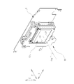
- a control board 18 is connected to the vibration isolator 15.
- Flexible printed circuit boards 90 to 92 which will be described later, are used for connecting the vibration isolator 15 and the control board 18.
- the control board 18 is provided with a CPU 93 (Central Processing Unit; see FIG. 9).
- the CPU 93 is a general-purpose processor that executes software (program) and functions as various processing units.
- the CPU 93 controls the operation of each part of the digital camera 10 including the vibration isolator 15 and the image pickup element 16.
- the vibration isolator 15 moves the image sensor 16 under the control of the CPU 93 provided on the control board 18. More specifically, the vibration isolator 15 has an X-axis direction parallel to the side 19 of the image pickup surface 17 of the image pickup element 16 and orthogonal to the side 19, that is, the side 19 in the direction of canceling the blur.
- the image pickup element 16 is moved in the Y-axis direction parallel to the side 20 intersecting at an angle of 90 °, and the image pickup element 16 is rotated in the Z-axis direction orthogonal to the X-axis direction and the Y-axis direction.
- the word “orthogonal” includes not only the meaning of perfect orthogonality but also the meaning of substantially orthogonality including errors allowed in design and manufacturing. Further, in the present specification, the word “parallel” includes not only the meaning of perfect parallelism but also the meaning of substantially parallelism including errors allowed in design and manufacturing.
- the optical axis OA is parallel to the Z axis.
- the "optical axis OA" refers to the optical axis of the subject light incident on the image pickup surface 17 through the image pickup lens 12. It should be noted that the blur correction includes not only the meaning of eliminating the blur but also the meaning of reducing the blur.
- the side of the side 19 is expressed as “down”, and the side opposite to the side 19 in the Y-axis direction is expressed as “up”. Further, the side of the side 20 is expressed as “left”, and the side opposite to the side 20 in the X-axis direction is expressed as "right”. Further, the side where the subject light is incident on the image pickup surface 17 in the Z-axis direction (that is, the side where the image pickup lens 12 is located) is referred to as "front”, and the side opposite to the side where the subject light is incident is referred to as "rear”.
- the vibration isolator 15 includes a holding portion 30 and a supporting portion 31.
- the support portion 31 includes a fixing member 32 and a yoke 33.
- the holding portion 30 includes a circuit board 16A (see FIG. 15) on which the image pickup element 16 is mounted, and is integrally provided with components such as coils 60 to 62 and magnetic bodies 65 to 67 and 75, which will be described later.
- the holding portion 30 is arranged between the fixing member 32 and the yoke 33 via a ball 35, a ball 36, and a ball 37 of the same size.
- the holding portion 30 can be moved in the X-axis direction and the Y-axis direction with respect to the fixing member 32 and the yoke 33 by the balls 35 to 37, and can be rotated in the Z-axis direction.
- the fixing member 32 holds a magnet 40, a magnet 41, a magnet 42, and a magnet 43.
- the magnets 40 to 43 are attached to the front surface of the fixing member 32 facing the holding portion 30.
- Each of the magnets 40 to 43 is a set of a plate-shaped magnet having an N pole directed toward the holding portion 30 side and a strip-shaped magnet having an S pole directed toward the holding portion 30 side.
- the magnet 40 is arranged in the center of the upper part of the fixing member 32 so that its long side is along the X-axis direction.
- the magnet 41 and the magnet 42 are arranged along the Y-axis direction.
- the magnet 41 is arranged in the upper left corner of the fixing member 32 so that its long side is along the Y-axis direction.
- the magnet 42 is arranged in the lower left corner of the fixing member 32 so that its long side is along the Y-axis direction.
- the magnet 43 is arranged in the lower right corner of the fixing member 32 so that its long side is along the X-axi
- a plate 45, a plate 46, and a plate 47 are attached to the front surface of the fixing member 32.
- the plate 45 is arranged between the magnet 42 and the magnet 43 in the lower center of the fixing member 32.
- the plate 46 is the upper left corner of the fixing member 32 and is located below the magnet 41.
- the plate 47 is located in the upper right corner of the fixing member 32 and is arranged to the right of the magnet 40.
- the plate 45 supports the rolling of the ball 35, the plate 46 supports the rolling of the ball 36, and the plate 47 supports the rolling of the ball 37.
- a magnet 48 is attached between the magnet 43 and the plate 45.
- the magnet 48 is arranged adjacent to the plate 45.
- the term "adjacent" as used herein means that the distance in the XY plane is, for example, within 1 cm.
- the fixing member 32 is formed with a square-shaped regulation opening 51 that regulates the movement range of the holding portion 30 in the XY plane.
- the regulation opening 51 is formed between the magnet 42 and the plate 46 in the lower left corner of the fixing member 32.
- the fixing member 32 is provided with female screws 52 to 54 via a spacer.
- the female screw 52 is provided in the lower center of the fixing member 32
- the female screw 53 is provided in the upper right corner of the fixing member 32
- the female screw 54 is provided in the upper left corner of the fixing member 32.
- a through hole 55 for passing the flexible printed substrates 90 to 92, which will be described later, is provided in the center of the fixing member 32.
- the holding unit 30 holds the image pickup device 16 and holds the coils 60 to 62.
- the image pickup device 16 is arranged in the central portion of the holding portion 30.
- the coil 60 is located at the center of the upper part of the holding portion 30 and at a position facing the magnet 40 in the Z-axis direction.
- the coil 61 is located in the upper left corner of the holding portion 30 at a position facing the magnet 41 in the Z-axis direction.
- the coil 62 is located in the lower left corner of the holding portion 30 at a position facing the magnet 42 in the Z-axis direction.
- the coil 60 is arranged so that its long side is along the X-axis direction.
- the coil 61 and the coil 62 are arranged along the Y-axis direction.
- the coil 61 and the coil 62 are arranged so that their long sides are along the Y-axis direction, respectively.
- Magnetic materials 65 to 67 are attached to the front surface of the holding portion 30 facing the yoke 33.
- the magnetic bodies 65 to 67 are, for example, thin plate pieces made of iron.
- the magnetic body 65 Since the coil 60 is arranged at a position facing the magnet 40 in the Z-axis direction as described above, the magnetic body 65 is also arranged at a position facing the magnet 40 in the Z-axis direction. Therefore, the magnetic material 65 is attracted to the magnet 40. That is, the magnet 40 and the magnetic body 65 act as magnetic springs.
- the magnetic body 66 is also arranged at a position facing the magnet 41 in the Z-axis direction. Therefore, the magnetic material 66 is attracted to the magnet 41. That is, the magnet 41 and the magnetic body 66 also act as magnetic springs.
- the magnetic body 67 is also arranged at a position facing the magnet 42 in the Z-axis direction. Therefore, the magnetic body 67 is attracted to the magnet 42. That is, the magnet 42 and the magnetic body 67 also act as magnetic springs.
- Recesses 70 to 72 are formed on the rear surface of the holding portion 30 facing the fixing member 32.
- the recess 70 is located in the lower center of the holding portion 30 at a position facing the plate 45 in the Z-axis direction.
- the recess 71 is the upper left corner of the holding portion 30 and is arranged at a position facing the plate 46 in the Z-axis direction.
- the recess 72 is located in the upper right corner of the holding portion 30 at a position facing the plate 47 in the Z-axis direction.
- the recess 70 rotatably accommodates the ball 35
- the recess 71 rotatably accommodates the ball 36
- the recess 72 rotatably accommodates the ball 37.
- the size of the recesses 70 to 72 when viewed in a plan view from the Z-axis direction is larger than the diameter of the balls 35 to 37. Further, the depth of the recesses 70 to 72 in the Z-axis direction is smaller than the diameter of the balls 35 to 37.
- a magnetic body 75 is attached to a portion of the holding portion 30 facing the magnet 48 in the Z-axis direction.
- the magnetic body 75 and the magnet 48 are arranged at positions facing the magnetic bodies 65 to 67 with the image pickup element 16 interposed therebetween when viewed in a plan view from the Z-axis direction.
- the magnet 48 is arranged in the central portion of the diagonal region sandwiching the image pickup element 16 with respect to the substantially L-shaped arrangement region of the magnetic bodies 65 to 67 along the X-axis direction and the Y-axis direction. Has been done.
- the magnetic body 75 is arranged at a position facing the magnet 48 in the Z-axis direction as described above. Therefore, the magnetic material 75 is attracted to the magnet 48. That is, the magnet 48 and the magnetic body 75 also act as magnetic springs.
- a columnar protrusion 76 protruding toward the fixing member 32 is provided at a position facing the regulation opening 51 in the Z-axis direction.
- the protrusion 76 is inserted through the regulation opening 51. Therefore, the protrusion 76 acts as a regulating pin that regulates the movement of the holding portion 30 in the XY plane.
- the yoke 33 is a magnetic material such as a thin plate made of iron, and has a substantially L-shape following the arrangement of the magnets 40 to 42 and the coils 60 to 62.
- the yoke 33 constitutes a magnetic circuit with the magnets 40 to 42, and increases the magnetic flux received by the coils 60 to 62.
- Male screws 80 to 82 are attached to the yoke 33.
- the male screws 80 to 82 are fastened and fixed to the female screws 52 to 54 of the fixing member 32.
- the holding portion 30 is arranged between the fixing member 32 and the yoke 33, and the fixing member 32 and the yoke 33 are fixed to each other.
- the vibration isolator 15 includes sliding mechanisms 83 to 85.
- the sliding mechanism 83 has a ball 35, a plate 45, and a recess 70.
- the sliding mechanism 84 has a ball 36, a plate 46, and a recess 71.
- the sliding mechanism 85 has a ball 37, a plate 47, and a recess 72.
- the sliding mechanisms 83 to 85 allow the holding portion 30 to move with respect to the fixing member 32.
- the anti-vibration device 15 has sliding mechanisms 83 to 85 arranged at three locations so that the holding portion 30 can be stably moved with respect to the fixing member 32 and the yoke 33.
- the holding unit 30 holds the image pickup device 16. Therefore, the image sensor 16 also moves with the movement of the holding unit 30. Under the control of the CPU 93 provided on the control board 18, the holding unit 30 is moved in the direction of canceling the blur by the amount of canceling the blur.
- the vibration isolator 15 includes a pair of voice coil motors (VCM; Voice Coil Motor).
- VCM voice coil motors
- the pair of VCMs according to the present embodiment is a pair of a first VCM86 and a second VCM87, and corresponds to a driving unit within the scope of claims.
- the first VCM86 includes a pair of a magnet 40 and a coil 60, and a yoke 33, and generates power for moving the holding portion 30 in the Y-axis direction.
- the second VCM 87 includes a pair of a magnet 41 and a coil 61, a pair of a magnet 42 and a coil 62, and a yoke 33, and generates power for moving the holding portion 30 in the X-axis direction.
- the first VCM86 and the second VCM87 drive the holding portion 30 in an XY plane orthogonal to the optical axis OA. More specifically, the first VCM86 generates a power to move the holding portion 30 in the Y-axis direction by the magnetic force of the magnet 40 and the current flowing through the coil 60. Further, the second VCM 87 generates a power to move the holding portion 30 in the X-axis direction by the magnetic force of the magnet 41 and the current flowing through the coil 61, and the magnetic force of the magnet 42 and the current flowing through the coil 62.
- the holding unit 30 has three position detection sensors for detecting the position and the rotational posture. Specifically, a Hall element (not shown) is arranged at a position facing the magnets 41 to 43 in the Z-axis direction, and the position is detected by the magnetic field generated by the magnets 41 to 43. The Hall element is mounted on the flexible printed circuit board 91 and the circuit board 16A.
- the vibration isolator 15 is provided with a magnetic force applying mechanism 88.
- the magnetic force applying mechanism 88 includes magnets 40 to 42, magnets 48, magnetic bodies 65 to 67, and magnetic body 75.
- the magnetic force applying mechanism 88 applies a magnetic force that attracts the holding portion 30 to the fixing member 32 in the Z-axis direction. By this magnetic force, the holding portion 30 is urged toward the fixing member 32, and the rattling of the fixing member 32 in the Z-axis direction is eliminated.
- the position of the holding portion 30 arranged between the fixing member 32 and the yoke 33 and attached to the supporting portion 31 in the Z-axis direction is restricted by the magnetic force applying mechanism 88, and the positions in the Z-axis direction are regulated by the three sliding mechanisms 83 to 85. It is said to be movable. That is, the support portion 31 movably supports the holding portion 30 in a plane orthogonal to the optical axis OA.
- the holding portion 30 is provided with an image pickup element 16 and coils 60 to 62.
- the image pickup device 16 or the coils 60 to 62 are electrically connected to the control board 18 via a plurality of flexible printed circuit boards 90 to 92.
- Flexible printed circuit boards 90 to 92 correspond to flexible substrates within the scope of the claims.
- the control board 18 is provided with a CPU 93. In this embodiment, three flexible printed boards 90 to 92 are provided, but the present invention is not limited to this, and one or two may be provided, and four or more flexible printed boards may be provided.
- the first connector portions 95 and 97 and the fixed cushion portion 96 are provided on the rear surface of the holding portion 30.
- the first connector portions 95 and 97 and the fixed cushion portion 96 correspond to the first flexible substrate fixing portion within the scope of the claims.
- the first connector portion 95 is provided near the lower end of the holding portion 30, the fixed cushion portion 96 is provided near the left end of the holding portion 30, and the first connector portion 97 is provided near the right end of the holding portion 30.
- the first connector portions 95 and 97 are provided with a slot that fits into one end of the flexible printed circuit boards 90 and 92, and a terminal that is provided inside the slot and electrically connected to the wiring pattern of the flexible printed circuit boards 90 and 92.
- the fixed cushion portion 96 is, for example, a cushion made of a urethane material to which double-sided tape is attached to two sides, and fixes an intermediate portion between the circuit board 16A and the flexible printed circuit board 91.
- a second guide plate 98 is provided on the rear surface of the holding portion 30.
- the second guide plate 98 is a sheet of flat plate-shaped members arranged in parallel with the image pickup surface 17.
- the second guide plate 98 is attached to, for example, a mounting component 99 (see FIG. 15) of the circuit board 16A of the image pickup element 16 via double-sided tape or the like, and a PET (polyethylene terephthalate) resin sheet is used.
- a PET polyethylene terephthalate
- FIG. 8 some mounting parts and the like of the circuit board 16A are omitted in order to prevent the drawings from becoming complicated.
- the second guide plate 98 comes into contact with the flexible printed substrates 90 to 92, as will be described later.
- control board 18 is located behind the vibration isolator 15. Further, a first guide plate 110 (see also FIG. 5), which will be described later, is provided on the rear side of the control board 18. The control board 18 and the first guide plate 110 are fixed to the camera body 11.
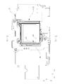
- the control board 18 is provided with a through hole 100 through which the flexible printed circuit boards 90 to 92 pass through, and second connector portions 101 to 103.
- the second connector portions 101 to 103 correspond to the second flexible substrate fixing portion in the claims.
- the second connector portions 101 to 103 are arranged on the rear surface 18B on the opposite side of the front surface 18A of the control board 18 facing the holding unit 30 (the surface facing the image pickup element 16; see FIGS. 5 and 13).
- the second connector portions 101 to 103 are arranged around the through hole 100.
- the flexible printed circuit boards 90 and 92 are connected to the first connector portions 95 and 97. .. Specifically, one end of the flexible printed circuit board 90 is connected to the first connector portion 95, and one end of the flexible printed circuit board 92 is connected to the first connector portion 97.
- the flexible printed circuit board 90 is electrically connected to the image pickup element 16 by being connected to the first connector portion 95, and the flexible printed circuit board 92 is connected to the image pickup element 16 by being connected to the first connector portion 97. It is electrically connected to a circuit board 16A or the like to supply electric power.
- the flexible printed substrate 91 is electrically connected to the coils 60 to 62 and a Hall element (not shown) via a solder portion.
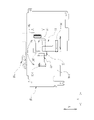
- the flexible printed substrates 90 to 92 fixed by the first connector portions 95 and 97 and the fixed cushion portion 96 extend in the center direction (direction toward the center CL) of the image pickup element 16 in the XY plane parallel to the image pickup surface 17. ing. Specifically, in the flexible printed circuit board 90 connected to the first connector portion 95, a portion extending from the first connector portion 95 is arranged along the Y-axis direction, and the flexible printed circuit board is fixed by the fixed cushion portion 96. In the substrate 91, a portion extending from the fixed cushion portion 96 is arranged along the X-axis direction, and in the flexible printed circuit board 92 connected to the first connector portion 97, a portion extending from the first connector portion 97 is X. Arranged along the axial direction.
- the central CL of the image pickup device 16 here means the center of the image pickup surface 17.
- the other ends of the flexible printed circuit boards 90 to 92 are connected to the second connector portions 101 to 103, respectively.
- the flexible printed circuit boards 90 to 92 one ends of which are connected to the first connector portions 95 and 97 and the fixed cushion portion 96, respectively, penetrate through the through holes 55 of the fixing member 32 and the through holes 100 of the control board 18. Then, it projects toward the rear surface 18B of the control board 18. Further, the flexible printed substrates 90 to 92 penetrating the through hole 100 project to the rear surface 18B side in a state of being bent by 180 °.
- the other end of the flexible printed circuit board 90 is connected to the second connector portion 101, and the other end of the flexible printed circuit board 91 is connected to the second connector portion 102 through the through hole 100 of the control board 18.
- the other end of the flexible printed circuit board 92 is connected to the second connector portion 103.
- the image sensor 16 or the coils 60 to 62 and the control board 18 are electrically connected via the flexible printed circuit boards 90 to 92.
- the through hole 100 has a shape in which at least two substantially rectangles are overlapped, and in the present embodiment, it has a shape in which three substantially rectangles are overlapped. That is, the through hole 100 has a shape in which a substantially rectangular region 100A to which the flexible printed substrate 90 moves, a substantially rectangular region 100B to which the flexible printed substrate 91 moves, and a substantially rectangular region 100C to which the flexible printed substrate 92 moves are overlapped. Is. As a result, the space where the flexible printed boards 90 to 92 move is concentrated in one place, and a part of the areas 100A to 100C where the flexible printed boards 90 to 92 move overlaps, so that the space can be saved. Can be done.
- the first guide plate 110 is provided on the rear surface 18B side with respect to the control board 18, and comes into contact with the flexible printed circuit boards 90 to 92. As described above, the flexible printed substrates 90 to 92 also come into contact with the second guide plate 98 located on the image pickup device 16 side.
- the first guide plate 110 corresponds to the first plate in the claims
- the second guide plate 98 corresponds to the second plate in the claims.
- the first guide plate 110 is provided with fluorine tapes 111 to 113 as friction reducing portions and a heat conductive sheet 114.
- the fluorine tapes 111 to 113 are attached at positions where they come into contact with the flexible printed substrates 90 to 92.
- the friction reducing portion is not limited to the fluorine tape, and may be any material having a low coefficient of friction with respect to the flexible printed substrates 90 to 92.
- the second guide plate 98 may be provided with a friction reducing portion at a position where it comes into contact with the flexible printed substrates 90 to 92.
- the heat conductive sheet 114 is formed of, for example, silicon rubber, and is provided at a position in contact with the control substrate 18, specifically, a position in contact with a mounting component such as a CPU 93.
- the heat conductive sheet 114 conducts heat from the control substrate 18 to the first guide plate 110.
- the first guide plate 110 is made of at least a part of a material having a heat dissipation effect, for example, a copper plate. As a result, the heat conducted from the control substrate 18 conducted through the heat conductive sheet 114 is easily dissipated.
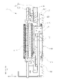
- FIG. 15 shows a cross-sectional view of a main part cut at a position where the flexible printed substrate 90 comes into contact with the first guide plate 110 and the second guide plate 98.
- the flexible printed board 90 is sandwiched between the first guide plate 110 and the second guide plate 98, and is connected to the first connector portion 95 and the second connector portion 101 in a state of being bent by 180 °. That is, the flexible printed substrate 90 has a semicircular bent portion 90A.
- the distance between the first connector portion 95 and the second connector portion 101 in the longitudinal direction of the flexible printed circuit board 90, that is, the Y-axis direction is L1
- the diameter of the bent portion 90A is d
- the length of the flexible printed circuit board 90 in the Y-axis direction is L2
- the relationship is L2> L1 + ⁇ d / 2.
- the length L2 excludes the portion where the flexible printed circuit board 90 is connected to the first connector portion 95 and the second connector portion 101 (the portion inserted into the first connector portion 95 and the second connector portion 101).
- the length is L2> L1 + ⁇ d / 2 in all the displacement regions, and the drive load is always reduced.
- FIG. 15 shows the dimensional relationship between the flexible printed circuit board 90 and the first connector portion 95 and the second connector portion 101, the flexible printed circuit board 91, the fixed cushion portion 96, and the second connector portion 102 are shown.
- the dimensional relationship between the flexible printed circuit board 92 and the first connector portion 97 and the second connector portion 103 is also expressed by the same equation.
- the first guide plate 110 has different heights in the Z-axis direction for each of the flexible printed substrates 90 to 92. That is, the first guide plate 110 has a stepped shape having different heights in the Z-axis direction with respect to the positions of contact with the flexible printed substrates 90 to 92.
- the fluorine tape 111 that comes into contact with the flexible printed substrate 90 is located inside the recess 110A that is one step recessed with respect to the periphery.
- the fluorine tape 112 that comes into contact with the flexible printed substrate 91 is located outside the recess 110A. That is, the first guide plate 110 has different heights in the Z-axis direction with respect to the position of contact with the flexible printed substrate 90 and the position of contact with the flexible printed substrate 91, and has a stepped shape between the two. As a result, the drive load can be adjusted by changing the bending radius for each of the flexible printed substrates 90 to 92.
- connection between the other end of the flexible printed circuit board 90 and the second connector portion 101 will be described with reference to FIGS. 16 and 17.
- the connection between the flexible printed circuit boards 91 and 92 and the second connector portions 102 and 103 has the same structure.
- connection between the flexible printed circuit boards 90 to 92 and the first connector portions 95 and 97 and the fixed cushion portion 96 may have the same structure.
- the other end of the flexible printed substrate 90 is provided with a fitting portion 90B and a pair of convex portions 90C.
- the fitting portion 90B has a large thickness dimension and fits into the slot 101A of the second connector portion 101.
- the slot 101A is formed in a groove shape in accordance with the fitting portion 90B, and a terminal (not shown) is provided inside.
- the convex portion 90C protrudes from both sides in the width direction of the fitting portion 90B, and when the fitting portion 90B is fitted with the slot 101A, the convex portion 90C is locked to a concave portion (not shown) formed inside the slot 101A. .. This prevents the flexible printed circuit board 90 from being easily detached from the second connector portion 101.
- the flexible printed substrate 90 is arranged so as to extend in the X-axis direction as described above.
- Reference numeral 90D indicates a linear portion extending in the X-axis direction.
- the straight line portion 90D and the second connector portion 101 are arranged so as to be displaced with respect to the Y-axis direction. Therefore, a crank-shaped position absorbing portion 90E is provided in a part of the fitting portion 90B or in the vicinity of the fitting portion 90B. As shown in FIG. 16B, by providing the position absorbing portion 90E, the linear portion 90D absorbs the portion shifted in the Y-axis direction, and the second connector portion 101 and the flexible printed circuit board 90 are also provided. Make sure that it can be connected to the end. This improves the degree of freedom in design for arranging the flexible printed circuit board 90.
- the second connector portion 101 is provided in a direction diagonally intersecting the XY plane. That is, the direction in which the slot 101A of the second connector portion 101 is arranged has an inclination of an angle ⁇ with respect to the XY plane.
- 17 (A) and 17 (B) are cross sections orthogonal to the Y-axis direction and along the X-axis direction.
- the fitting portion 90B is fitted into the slot 101A and the flexible printed circuit board 90 is connected to the second connector portion 101
- the other end of the flexible printed circuit board 90 is with respect to the XY plane.
- the flexible printed circuit board 90 can avoid contact with the control board 18 and can surely come into contact with the fluorine tape 111 attached to the first guide plate 110, and the drive load can be stabilized.
- the CPU 93 determines the difference between the position of the holding unit 30 detected by a Hall element (not shown) and the target position of the holding unit 30 for correcting the camera shake. Therefore, feedback control is performed to drive the first VCM86 and the second VCM87 so as to eliminate the difference.
- the holding unit 30 moves together with the image sensor 16 and is connected to the holding unit 30. It receives a drive load from the flexible printed boards 90 to 92.
- the through hole 100 is formed in the control board 18, and the image sensor 16 or the coils 60 to 62 and the control board 18 are electrically connected by the flexible printed circuit boards 90 to 92 through which the through hole 100 is penetrated. Therefore, the bending radius of the flexible printed circuit boards 90 to 92 can be made large, and the drive load when the first VCM86 and the second VCM87 are driven can be reduced.
- a flexible printed circuit board is passed outside the control board as in a conventional image pickup device without passing through a through hole, it is difficult to obtain a large bending radius because there is little space around the control board, or the bending radius is not passed. If you increase the size of the camera body, the size of the camera body will increase.
- the present invention has a large bending radius of the flexible printed circuit board due to the above configuration, and does not require a space around the control board. Therefore, the size of the camera body can be reduced. Further, since the drive load can be reduced, the drive unit can be miniaturized, and from this point as well, the camera body can be miniaturized.
- the straight portion of the flexible printed substrate 90 to 92 can be arranged long.
- the straight portion of the flexible printed circuit board is likely to be twisted and the drive load is large. Since the straight portion can be arranged long, the drive load when the first VCM86 and the second VCM87 are driven can be reduced.
- the bending radius of the flexible printed boards 90 to 92 can be kept constant and can be smoothly moved. Therefore, the drive load can be reduced. If there is no guide for the flexible printed circuit board as in the conventional image pickup device, the bending radius changes depending on the position where the holding portion moves, and the drive load becomes unstable. However, in the present invention, the bending radius is kept constant. Therefore, the drive load can be kept below a certain level. Further, since the first guide plate 110 is provided with the fluorine tapes 111 to 113 as the friction reducing portion, the drive load can be further reduced.
- a plurality of flexible printed circuit boards 90 to 92 are provided, and in one flexible printed circuit board 90, a portion extending from the first connector portion 95 is arranged along the Y-axis direction, and another flexible printed circuit board 90 is provided.
- the substrate 91 is arranged along the X-axis direction.
- the drive load in the direction orthogonal to the extending direction becomes large, but since the extending direction is dispersed in this way, the driving load in one direction can be reduced.
- the through hole 100 is formed in the control board 18 as a relief portion through which the flexible printed circuit boards 90 to 92 are penetrated, but the present invention is not limited to this, and as shown in FIGS. 18 and 19.
- a notch is formed in the control board 18 and the flexible printed circuit boards 90 to 92 are passed through the control board 18.
- the configuration is the same as that of the first embodiment except that the control board 18 is formed with a notch instead of the through hole, and the description thereof will be omitted.
- the notch 120 has a shape in which at least two substantially rectangles are overlapped, and in the present embodiment, it has a shape in which three substantially rectangles are overlapped. That is, it is a shape in which substantially rectangular areas in which the flexible printed substrates 90 to 92 move are overlapped. In the notch 120, the substantially rectangular area where the flexible printed substrates 90 to 92 move is the same as the position with respect to the through hole 100 in the first embodiment.
- the notch 120 extends along the Y-axis direction from the substantially rectangular area where the flexible printed substrate 91 moves, and is connected to one side 18C.
- the flexible printed substrate 90 is sandwiched between the first guide plate 110 and the second guide plate 98 and has a semicircular bent portion 90A, as in the first embodiment.
- One end of the flexible printed circuit board 90 is electrically connected to the first connector portion 95.
- the flexible printed circuit board 90 passes through the notch 120 and projects toward the rear surface 18B of the control board 18.
- the other end of the flexible printed circuit board 90 is electrically connected to the second connector portion 101.
- the flexible printed circuit board 92 one end is electrically connected to the first connector portion 97 and the other end is electrically connected to the second connector portion 102.
- the flexible printed circuit board 91 is also electrically connected to the second connector portion 102.
- the distance between the first connector portion 95 and the second connector portion 101 in the longitudinal direction of the flexible printed circuit board 90, that is, the Y-axis direction is L1
- the diameter of the bent portion 90A is d.
- FIG. 19 shows the dimensional relationship between the flexible printed circuit board 90 and the first connector portion 95 and the second connector portion 101, the flexible printed circuit board 91, the fixed cushion portion 96, and the second connector portion 102 are shown.
- the dimensional relationship between the flexible printed circuit board 92 and the first connector portion 97 and the second connector portion 103 is also expressed by the same equation.
- the flexible printed circuit boards 90 to 92 are arranged in the same arrangement as in the first embodiment, and the flexible printed circuit boards are made to pass through the notch 120. Since the image pickup device 16 or the coils 60 to 62 and the control board 18 are electrically connected by the printed circuit boards 90 to 92, the effect of reducing the drive load and the like can be obtained as in the first embodiment. ..
- the CPU 93 is exemplified as a processor that controls the operation of the vibration isolator 15, but a processor as a hardware structure of a processing unit that executes various processes such as the CPU 93 is a processor.
- Programmable Logic Device is a processor whose circuit configuration can be changed after the manufacture of GPU (Graphical Processing Unit), FPGA (Field Programmable Gate Array), etc., in place of or in addition to the CPU. PLD), a dedicated electric circuit, which is a processor having a circuit configuration specially designed for performing various processes, and the like.
- One processing unit may be composed of one of these various processors, or a combination of two or more processors of the same type or different types (for example, a plurality of FPGAs, a combination of a CPU and an FPGA, or a CPU). And GPU in combination, etc.). Further, a plurality of processing units may be configured by one processor. As an example of configuring a plurality of processing units with one processor, first, as represented by a computer such as a client or a server, one processor is configured by a combination of one or more CPUs and software. There is a form in which this processor functions as a plurality of processing units.
- SoC System On Chip
- the various processing units are configured by using one or more of the above-mentioned various processors as a hardware-like structure.
- the hardware-like structure of these various processors is, more specifically, an electric circuit (circuitry) in which circuit elements such as semiconductor elements are combined.
- the present invention can be applied to image pickup devices such as smartphones and video cameras in addition to digital cameras.
Landscapes
- Engineering & Computer Science (AREA)
- Physics & Mathematics (AREA)
- General Physics & Mathematics (AREA)
- Multimedia (AREA)
- Signal Processing (AREA)
- Microelectronics & Electronic Packaging (AREA)
- Adjustment Of Camera Lenses (AREA)
- Studio Devices (AREA)
- Camera Bodies And Camera Details Or Accessories (AREA)
Priority Applications (2)
| Application Number | Priority Date | Filing Date | Title |
|---|---|---|---|
| JP2022555592A JP7792344B2 (ja) | 2020-10-09 | 2021-10-08 | 撮像装置 |
| US18/296,968 US12348867B2 (en) | 2020-10-09 | 2023-04-06 | Imaging device |
Applications Claiming Priority (2)
| Application Number | Priority Date | Filing Date | Title |
|---|---|---|---|
| JP2020171138 | 2020-10-09 | ||
| JP2020-171138 | 2020-10-09 |
Related Child Applications (1)
| Application Number | Title | Priority Date | Filing Date |
|---|---|---|---|
| US18/296,968 Continuation US12348867B2 (en) | 2020-10-09 | 2023-04-06 | Imaging device |
Publications (1)
| Publication Number | Publication Date |
|---|---|
| WO2022075454A1 true WO2022075454A1 (ja) | 2022-04-14 |
Family
ID=81126131
Family Applications (1)
| Application Number | Title | Priority Date | Filing Date |
|---|---|---|---|
| PCT/JP2021/037364 Ceased WO2022075454A1 (ja) | 2020-10-09 | 2021-10-08 | 撮像装置 |
Country Status (3)
| Country | Link |
|---|---|
| US (1) | US12348867B2 (https=) |
| JP (1) | JP7792344B2 (https=) |
| WO (1) | WO2022075454A1 (https=) |
Families Citing this family (1)
| Publication number | Priority date | Publication date | Assignee | Title |
|---|---|---|---|---|
| JP2023077992A (ja) * | 2021-11-25 | 2023-06-06 | キヤノン株式会社 | 撮像装置 |
Citations (2)
| Publication number | Priority date | Publication date | Assignee | Title |
|---|---|---|---|---|
| JP2020064281A (ja) * | 2018-10-16 | 2020-04-23 | キヤノン株式会社 | 撮像装置、電子機器 |
| WO2020202811A1 (ja) * | 2019-03-29 | 2020-10-08 | ソニー株式会社 | 像ぶれ補正装置及び撮像装置 |
Family Cites Families (10)
| Publication number | Priority date | Publication date | Assignee | Title |
|---|---|---|---|---|
| JP4571902B2 (ja) * | 2005-10-20 | 2010-10-27 | Hoya株式会社 | 撮像装置のフレキシブル基板配設構造 |
| JP2012156581A (ja) * | 2011-01-21 | 2012-08-16 | Sanyo Electric Co Ltd | 発熱素子体の放熱構造 |
| JP5830639B2 (ja) * | 2011-02-02 | 2015-12-09 | パナソニックIpマネジメント株式会社 | 撮像装置 |
| JP2012195456A (ja) * | 2011-03-16 | 2012-10-11 | Toshiba Corp | フレキシブル配線モジュール及びフレキシブル配線装置 |
| US9596387B2 (en) * | 2011-08-02 | 2017-03-14 | Magna Electronics Inc. | Vehicular camera system |
| JP6348683B2 (ja) * | 2013-03-28 | 2018-06-27 | オリンパス株式会社 | 撮像装置 |
| JP6942517B2 (ja) * | 2017-04-27 | 2021-09-29 | キヤノン株式会社 | 撮像装置およびその製造方法 |
| JP7098413B2 (ja) | 2018-05-17 | 2022-07-11 | キヤノン株式会社 | 撮像装置 |
| US11122190B2 (en) * | 2018-10-16 | 2021-09-14 | Canon Kabushiki Kaisha | Image pickup apparatus with movable unit and control unit connected together by flexible boards |
| JP2021173943A (ja) * | 2020-04-28 | 2021-11-01 | キヤノン株式会社 | 像ブレ補正装置および撮像装置 |
-
2021
- 2021-10-08 WO PCT/JP2021/037364 patent/WO2022075454A1/ja not_active Ceased
- 2021-10-08 JP JP2022555592A patent/JP7792344B2/ja active Active
-
2023
- 2023-04-06 US US18/296,968 patent/US12348867B2/en active Active
Patent Citations (2)
| Publication number | Priority date | Publication date | Assignee | Title |
|---|---|---|---|---|
| JP2020064281A (ja) * | 2018-10-16 | 2020-04-23 | キヤノン株式会社 | 撮像装置、電子機器 |
| WO2020202811A1 (ja) * | 2019-03-29 | 2020-10-08 | ソニー株式会社 | 像ぶれ補正装置及び撮像装置 |
Also Published As
| Publication number | Publication date |
|---|---|
| US12348867B2 (en) | 2025-07-01 |
| US20230247294A1 (en) | 2023-08-03 |
| JPWO2022075454A1 (https=) | 2022-04-14 |
| JP7792344B2 (ja) | 2025-12-25 |
Similar Documents
| Publication | Publication Date | Title |
|---|---|---|
| US11754851B2 (en) | Lens driving apparatus having three ball members and opening in frame | |
| US8792166B2 (en) | Image blur correction apparatus and image pickup unit having image blur correction apparatus | |
| US9904072B2 (en) | Lens driving device | |
| JP5117359B2 (ja) | 像振れ補正装置、撮像レンズユニット、及びカメラユニット | |
| KR102687901B1 (ko) | 렌즈 구동 장치, 카메라 모듈, 및 카메라 탑재 장치 | |
| US12126885B2 (en) | Camera module with sensor shifting module | |
| WO2022122008A1 (zh) | 驱动装置和摄像模组 | |
| CN116482916A (zh) | 相机模块 | |
| US12407927B2 (en) | Sensor shifting module and camera module having the same | |
| US20240168362A1 (en) | Lens driving apparatus and camera module including the same | |
| CN109586610B (zh) | 图像稳定设备、使用图像稳定设备的光学设备和驱动设备 | |
| JP5295836B2 (ja) | 像振れ補正装置、撮像レンズユニット、及びカメラユニット | |
| WO2022180976A1 (ja) | 撮像素子ユニット、および撮像装置 | |
| US12348867B2 (en) | Imaging device | |
| US20230403452A1 (en) | Camera module with optical image stabilization actuator | |
| JP5912825B2 (ja) | レンズ駆動装置 | |
| CN117917091A (zh) | 相机致动器和包括该相机致动器的相机装置 | |
| JP2025114732A (ja) | 撮像素子ユニット、および撮像装置 | |
| CN117413525A (zh) | 相机致动器和包括该相机致动器的相机设备 | |
| JP7075029B2 (ja) | レンズ駆動装置、カメラモジュール、及びカメラ搭載装置 | |
| JP7549271B2 (ja) | 超音波駆動装置、カメラモジュール、及びカメラ搭載装置 | |
| US20250080848A1 (en) | Shake correction device and imaging apparatus | |
| US12108133B2 (en) | Lens driving device and camera module including lens driving device | |
| JP7093050B2 (ja) | レンズ駆動装置、カメラモジュール、及びカメラ搭載装置 | |
| JP7727180B2 (ja) | 光学素子駆動装置、カメラモジュール及びカメラ搭載装置 |
Legal Events
| Date | Code | Title | Description |
|---|---|---|---|
| 121 | Ep: the epo has been informed by wipo that ep was designated in this application |
Ref document number: 21877753 Country of ref document: EP Kind code of ref document: A1 |
|
| ENP | Entry into the national phase |
Ref document number: 2022555592 Country of ref document: JP Kind code of ref document: A |
|
| NENP | Non-entry into the national phase |
Ref country code: DE |
|
| 122 | Ep: pct application non-entry in european phase |
Ref document number: 21877753 Country of ref document: EP Kind code of ref document: A1 |