WO2022075086A1 - バルブ装置 - Google Patents
バルブ装置 Download PDFInfo
- Publication number
- WO2022075086A1 WO2022075086A1 PCT/JP2021/035042 JP2021035042W WO2022075086A1 WO 2022075086 A1 WO2022075086 A1 WO 2022075086A1 JP 2021035042 W JP2021035042 W JP 2021035042W WO 2022075086 A1 WO2022075086 A1 WO 2022075086A1
- Authority
- WO
- WIPO (PCT)
- Prior art keywords
- flow path
- valve
- axis
- opening
- axial direction
- Prior art date
- Legal status (The legal status is an assumption and is not a legal conclusion. Google has not performed a legal analysis and makes no representation as to the accuracy of the status listed.)
- Ceased
Links
Images


Classifications
-
- F—MECHANICAL ENGINEERING; LIGHTING; HEATING; WEAPONS; BLASTING
- F16—ENGINEERING ELEMENTS AND UNITS; GENERAL MEASURES FOR PRODUCING AND MAINTAINING EFFECTIVE FUNCTIONING OF MACHINES OR INSTALLATIONS; THERMAL INSULATION IN GENERAL
- F16K—VALVES; TAPS; COCKS; ACTUATING-FLOATS; DEVICES FOR VENTING OR AERATING
- F16K31/00—Actuating devices; Operating means; Releasing devices
- F16K31/02—Actuating devices; Operating means; Releasing devices electric; magnetic
- F16K31/04—Actuating devices; Operating means; Releasing devices electric; magnetic using a motor
- F16K31/041—Actuating devices; Operating means; Releasing devices electric; magnetic using a motor for rotating valves
-
- F—MECHANICAL ENGINEERING; LIGHTING; HEATING; WEAPONS; BLASTING
- F16—ENGINEERING ELEMENTS AND UNITS; GENERAL MEASURES FOR PRODUCING AND MAINTAINING EFFECTIVE FUNCTIONING OF MACHINES OR INSTALLATIONS; THERMAL INSULATION IN GENERAL
- F16K—VALVES; TAPS; COCKS; ACTUATING-FLOATS; DEVICES FOR VENTING OR AERATING
- F16K11/00—Multiple-way valves, e.g. mixing valves; Pipe fittings incorporating such valves
- F16K11/02—Multiple-way valves, e.g. mixing valves; Pipe fittings incorporating such valves with all movable sealing faces moving as one unit
- F16K11/06—Multiple-way valves, e.g. mixing valves; Pipe fittings incorporating such valves with all movable sealing faces moving as one unit comprising only sliding valves, i.e. sliding closure elements
- F16K11/072—Multiple-way valves, e.g. mixing valves; Pipe fittings incorporating such valves with all movable sealing faces moving as one unit comprising only sliding valves, i.e. sliding closure elements with pivoted closure members
- F16K11/074—Multiple-way valves, e.g. mixing valves; Pipe fittings incorporating such valves with all movable sealing faces moving as one unit comprising only sliding valves, i.e. sliding closure elements with pivoted closure members with flat sealing faces
-
- F—MECHANICAL ENGINEERING; LIGHTING; HEATING; WEAPONS; BLASTING
- F16—ENGINEERING ELEMENTS AND UNITS; GENERAL MEASURES FOR PRODUCING AND MAINTAINING EFFECTIVE FUNCTIONING OF MACHINES OR INSTALLATIONS; THERMAL INSULATION IN GENERAL
- F16K—VALVES; TAPS; COCKS; ACTUATING-FLOATS; DEVICES FOR VENTING OR AERATING
- F16K3/00—Gate valves or sliding valves, i.e. cut-off apparatus with closing members having a sliding movement along the seat for opening and closing
- F16K3/02—Gate valves or sliding valves, i.e. cut-off apparatus with closing members having a sliding movement along the seat for opening and closing with flat sealing faces; Packings therefor
- F16K3/04—Gate valves or sliding valves, i.e. cut-off apparatus with closing members having a sliding movement along the seat for opening and closing with flat sealing faces; Packings therefor with pivoted closure members
- F16K3/06—Gate valves or sliding valves, i.e. cut-off apparatus with closing members having a sliding movement along the seat for opening and closing with flat sealing faces; Packings therefor with pivoted closure members in the form of closure plates arranged between supply and discharge passages
- F16K3/08—Gate valves or sliding valves, i.e. cut-off apparatus with closing members having a sliding movement along the seat for opening and closing with flat sealing faces; Packings therefor with pivoted closure members in the form of closure plates arranged between supply and discharge passages with circular plates rotatable around their centres
-
- F—MECHANICAL ENGINEERING; LIGHTING; HEATING; WEAPONS; BLASTING
- F16—ENGINEERING ELEMENTS AND UNITS; GENERAL MEASURES FOR PRODUCING AND MAINTAINING EFFECTIVE FUNCTIONING OF MACHINES OR INSTALLATIONS; THERMAL INSULATION IN GENERAL
- F16K—VALVES; TAPS; COCKS; ACTUATING-FLOATS; DEVICES FOR VENTING OR AERATING
- F16K31/00—Actuating devices; Operating means; Releasing devices
- F16K31/02—Actuating devices; Operating means; Releasing devices electric; magnetic
- F16K31/04—Actuating devices; Operating means; Releasing devices electric; magnetic using a motor
- F16K31/041—Actuating devices; Operating means; Releasing devices electric; magnetic using a motor for rotating valves
- F16K31/043—Actuating devices; Operating means; Releasing devices electric; magnetic using a motor for rotating valves characterised by mechanical means between the motor and the valve, e.g. lost motion means reducing backlash, clutches, brakes or return means
-
- F—MECHANICAL ENGINEERING; LIGHTING; HEATING; WEAPONS; BLASTING
- F16—ENGINEERING ELEMENTS AND UNITS; GENERAL MEASURES FOR PRODUCING AND MAINTAINING EFFECTIVE FUNCTIONING OF MACHINES OR INSTALLATIONS; THERMAL INSULATION IN GENERAL
- F16K—VALVES; TAPS; COCKS; ACTUATING-FLOATS; DEVICES FOR VENTING OR AERATING
- F16K31/00—Actuating devices; Operating means; Releasing devices
- F16K31/44—Mechanical actuating means
- F16K31/53—Mechanical actuating means with toothed gearing
- F16K31/535—Mechanical actuating means with toothed gearing for rotating valves
Definitions
- This disclosure relates to a valve device.
- valve device in which a first valve plate and a second valve plate are arranged in a fluid flow path of a housing has been proposed (see, for example, Patent Document 1).
- the first valve plate forms a first through hole and a second through hole.
- the second valve plate forms a third through hole.
- the second valve plate is arranged on one side in the axial direction with respect to the first valve plate.
- the second valve plate rotates around the axis so that the third through hole communicates with at least one of the first through hole and the second through hole. For example, when the third through hole communicates with the first through hole, the fluid is discharged from the first outlet port through the third through hole and the first through hole. When the third through hole communicates with the second through hole, the fluid is discharged from the second outlet port through the third through hole and the second through hole.
- the outlet port for discharging the fluid can be switched from one outlet port of the first outlet port and the second outlet port to the other outlet port.
- the present inventors have focused on the reduction of the frictional force between the first valve plate and the second valve plate in the above-mentioned valve device, and examined as follows.
- the fourth through hole constitutes a sealed area surrounded by a hole forming portion forming the fourth through hole, the second valve plate, and the bottom of the housing in the first valve plate.
- the air When air is sealed in the sealed area, the air expands and displaces the second valve plate to one side in the axial direction at high temperatures. Therefore, a gap is formed between the second valve plate and the first valve plate. On the other hand, at low temperatures, the air shrinks and attracts the second valve plate to the other side in the axial direction. This increases the frictional force between the first valve plate (ie, the fixed valve) and the second valve plate (ie, the drive valve).
- a valve device in a valve device, A housing that forms a fluid flow path through which fluid flows, A fixed valve that has an axis and forms a through chamber that is arranged in the fluid flow path and passes through the axis direction with the first flow path that is arranged in the fluid flow path when the direction in which the axis extends is the axis direction.
- a drive valve configured to allow the second flow path to communicate with the first flow path.
- the housing has a bottom that is formed to cover the through chamber from the other side in the axial direction.
- the upstream side flow path arranged on the upstream side in the fluid flow direction with respect to the drive valve and the fixed valve and the through chamber are communicated with each other by a communication passage.
- the sliding area between the fixed valve and the drive valve can be reduced by providing the through chamber.
- the upstream side passage and the penetrating room are communicated by a communication passage.
- a housing that forms a fluid flow path through which fluid flows
- a fixed valve that has an axis and forms a through chamber that is arranged in the fluid flow path and passes through the axis direction with the first flow path that is arranged in the fluid flow path when the direction in which the axis extends is the axis direction.
- a drive valve configured to allow the second flow path to communicate with the first flow path.
- the housing has a bottom that is formed to cover the through chamber from the other side in the axial direction.
- the downstream side flow path arranged on the downstream side in the fluid flow direction with respect to the drive valve and the fixed valve and the through chamber are communicated with each other by a communication passage.
- the sliding area between the fixed valve and the drive valve can be reduced by providing the through chamber.
- the downstream flow path and the penetrating room are communicated by a communication passage.
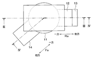
- FIG. 1 is a top view of the valve device according to the first embodiment of FIG. 1 from one side in the axial direction.
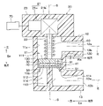
- FIG. 2 is a cross-sectional view taken along the line III-III in FIG.
- FIG. 2 is a sectional view taken along line IV-IV in FIG.
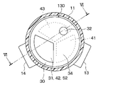
- FIG. 3 is a view of a drive valve and a fixed valve inside the valve device according to the first embodiment of FIG. 3 as viewed from one side in the axial direction, and the drive shaft and the spring are not shown.
- FIG. 5 is a sectional view taken along line VI-VI in FIG. FIG.
- FIG. 3 is a view of a drive valve and a fixed valve inside the valve device according to the first embodiment of FIG. 3 as viewed from one side in the axial direction, and the drive shaft and the spring are not shown.
- FIG. 7 is a cross-sectional view taken along the line VIII-VIII in FIG.
- FIG. 3 is a front view of the drive valve unit of FIG. 3 as viewed from one side in the axial direction.
- 9 is a side view of the drive valve unit of FIG. 9 as viewed from the outside in the radial direction with the axis as the center.
- FIG. 3 is a front view of the fixed valve unit of FIG. 3 as viewed from one side in the axial direction.
- FIG. 11 is a side view of the fixed valve unit of FIG.
- FIG. 3 is a front view of the gasket unit of FIG. 3 as viewed from one side in the axial direction. It is a side view which looked at the gasket alone of FIG. 13 from the outside in the radial direction about the axis line. It is a perspective view which shows the arrangement relation of the drive valve and a spring of FIG. 3, and is the figure which assists the explanation of the elastic force which a spring gives to a drive valve. It is the figure which looked at the drive valve and the fixed valve arranged in the housing of the valve device in inverse proportion from one side in the axial direction, and is the figure which the illustration of a drive shaft and a spring is omitted.
- FIG. 16 is a cross-sectional view taken along the line XVII-XVII in FIG. 16 in inverse proportion. It is a front view which saw the drive valve single body of FIG. 17 in inverse proportion from one side in the axial direction.
- FIG. 6 is a side view of the drive valve unit of FIG. 17 in inverse proportion as viewed from the outside in the radial direction with the axis as the center.
- FIG. 3 is a diagram for assisting the explanation of the elastic force applied to the drive valve by the spring of FIG. 3, and is a diagram showing a state in which the axis of the spring is tilted with respect to the axis of the drive shaft.
- FIG. 26 is a side view of the drive valve unit of FIG. 26 as viewed from the outside in the radial direction with the axis as the center. It is sectional drawing to assist the explanation of the drive valve and the fixed valve inside the housing of the valve device in 6th Embodiment, and is the figure which omits the illustration of a drive shaft and a spring.
- FIG. 26 is a side view of the drive valve unit of FIG. 26 as viewed from the outside in the radial direction with the axis as the center.
- FIG. 28 is a cross-sectional view taken along the line XXIX-XXIX in FIG. 28. It is a front view which saw the drive valve single body in 7th Embodiment from one side in the axial direction.
- FIG. 30 is a cross-sectional view taken along the line XXXI-XXXI in FIG. It is sectional drawing to assist the explanation of the drive valve and the fixed valve inside the housing of the valve apparatus in 7th Embodiment, and is the figure corresponding to FIG. 6 of 1st Embodiment. It is a front view which saw the drive valve single body in 8th Embodiment from one side in the axial direction.
- the valve device of the first embodiment will be described with reference to FIGS. 1, 2, 3, 4, 4, 5, 6, and the like.
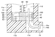
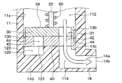
- the valve device of the present embodiment is provided in a cooling water circuit that circulates cooling water that is a fluid, and as shown in FIGS. 1, 2, 3, and 4, the housing 10, the actuator 20, and the drive are provided. It includes a valve 30, a fixed valve 40, a gasket 50, and a spring 60.
- the housing 10 includes a housing main body 11, an inlet pipe 12, and outlet pipes 13 and 14.
- the housing main body 11 has an axis S and is formed in a cylindrical shape centered on the axis S.
- the housing main body 11 forms a cooling water flow path 111 that constitutes a fluid flow path through which cooling water flows.
- the cooling water flow path 111 is formed by the inner wall 11a of the housing main body 11. Specifically, the cooling water flow path 111 includes an upstream side flow path 112 and downstream side flow paths 113 and 114.
- the upstream side flow path 112 is formed on one side of the axial direction Sa with respect to the bottom portion 110.
- the upstream side flow path 112 is arranged on the upstream side of the cooling water flow path 111 in the cooling water flow direction with respect to the drive valve 30 and the fixed valve 40.
- the upstream side flow path 112 is a flow path for circulating the cooling water flowing from the pipe flow path 12a of the inlet pipe 12 to the other side in the axial direction Sa.
- the axis direction Sa is the direction in which the axis S of the housing body 11 extends.
- the pipe flow path 12a of the inlet pipe 12 is connected to the upstream side flow path 112.
- the downstream flow path 114 is formed at the bottom 110 as shown in FIGS. 5 and 6.
- the downstream side flow path 114 is connected to the pipe flow path 14a of the outlet pipe 14.
- the downstream flow path 113 is formed at the bottom 110 as shown in FIGS. 7 and 8.
- the downstream side flow path 113 is connected to the pipe flow path 13a of the outlet pipe 13.
- the bottom portion 110 is arranged on the other side of the axial direction Sa with respect to the upstream side flow path 112, the drive valve 30, the fixed valve 40, and the gasket 50 in the housing main body 11.
- the bottom 110 supports the fixed valve 40 from the other side in the axial direction Sa via the gasket 50.
- the bottom 110 is formed so as to cover the opening 43 of the fixed valve 40.
- One side of the axial direction Ra of the inlet pipe 12 is connected to one side of the axial direction Sa of the housing main body 11 as shown in FIG. 3 or FIG.
- the inlet pipe 12 is formed in a cylindrical shape centered on the axis R.
- the inlet pipe 12 forms a pipe flow path 12a through which cooling water flows from the other side to one side in the axial direction Ra.
- the axis direction Ra is the direction in which the axis R extends.
- the pipe flow path 12a communicates with the upstream side flow path 112.
- an inlet port 12b is formed on the other side of the inlet pipe 12 in the axial direction Ra.
- the inlet port 12b is an inlet through which cooling water flows into the pipe flow path 12a.
- the axial direction Ra is a direction orthogonal to the axial direction Sa.
- outlet pipe 13 in the axial direction Ea is connected to the other side of the housing main body 11 in the axial direction Sa.
- the outlet pipe 13 is formed in a cylindrical shape centered on the axis E.
- the outlet pipe 13 forms a pipe flow path 13a for flowing cooling water from one side to the other side in the axial direction Ea.
- the axis direction Ea is the direction in which the axis E extends.
- the pipe flow path 13a communicates with the downstream side flow path 113.
- an outlet port 13b is formed on the other side of the outlet pipe 13 in the axial direction Ea.
- the outlet port 13b is an outlet from which the cooling water that has passed through the pipe flow path 13a is discharged.
- the axial direction Ea is a direction parallel to the axial direction Ra.
- one side of the axial direction Fa of the outlet pipe 14 is connected to the other side of the housing main body 11 in the axial direction Sa.
- the outlet pipe 14 is formed in a cylindrical shape centered on the axis F.
- the outlet pipe 14 forms a pipe flow path 14a for flowing cooling water from one side to the other side in the axial direction Fa.
- the axis direction Fa is the direction in which the axis F extends.
- the pipe flow path 14a communicates with the downstream flow path 114.
- An outlet port 14b is formed on the other side of the outlet pipe 14 in the axial direction Fa.
- the outlet port 14b is an outlet from which the cooling water that has passed through the pipe flow path 14a is discharged.
- the axial direction Fa is a direction that intersects the axial direction Ra.
- the housing main body 11 of the present embodiment is provided with an outer peripheral support portion 11b that supports a part of the annular portion 45 of the fixed valve 40 from the other side in the axial direction Sa via the gasket 50.
- the outer peripheral support portion 11b is formed so as to protrude inward in the radial direction about the axis S from the inner wall 11a of the housing main body 11.
- the actuator 20 includes an actuator device 21 and a housing 23.
- the actuator device 21 includes an electric motor 21a and a gear mechanism 21b.
- the electric motor 21a is controlled by the electronic control device 70 and outputs a rotational force to the gear mechanism 21b.
- a DC motor, a stepping motor, and an AC motor are used as the electric motor 21a of the present embodiment.
- the gear mechanism 21b includes a plurality of gears including the drive shaft 22, and transmits the rotational force output from the electric motor 21a by the mutual meshing of the plurality of gears to the drive valve 30.
- the drive shaft 22 is arranged in the upstream flow path 112 of the housing main body 11.
- the drive shaft 22 is arranged so that its axis coincides with the axis S.
- the drive shaft 22 is configured to be rotatable about the axis S.
- the other side of the drive shaft 22 in the axial direction is connected to the drive valve 30.
- the other side of the drive valve 30 in the axial direction is fixed to the drive valve 30 by press fitting.
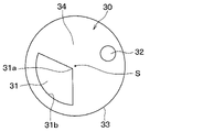
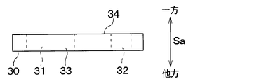
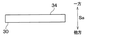
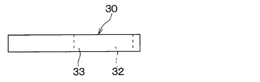
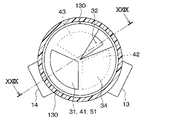
- the drive valve 30 is formed in a plate shape whose thickness direction coincides with the axial direction Sa. Specifically, the drive valve 30 is a disc valve formed in a disk shape centered on the axis S. The drive valve 30 is arranged so as to cover the openings 41, 42, 43 of the fixed valve 40 from one side in the axial direction Sa.
- a sliding surface that slides with respect to the fixed valve 40 is formed on the other side of the drive valve 30 in the axial direction Sa. Therefore, the drive valve 30 rotates about the axis S while sliding with respect to the fixed valve 40.
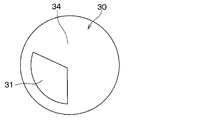
- the drive valve 30 forms a flow path opening 31 and a communication opening 32.
- the flow path opening 31 is formed so as to penetrate in the axial direction Sa (that is, the thickness direction).
- the flow path opening 31 has a fan shape in which the apex 31a is arranged radially inside the axis S and the circumferential portion 31b is arranged radially outside the axis S in the drive valve 30. It is open.
- the flow path opening 31 constitutes a second flow path through which cooling water flows, as will be described later.
- the communication opening 32 is opened in a circular shape in the drive valve 30.
- the communication opening 32 is arranged on the side opposite to the flow path opening 31 with respect to the axis S in the radial direction centered on the axis S.
- the communication opening 32 is arranged so as to be offset in the circumferential direction about the axis S with respect to the communication opening 32.
- the communication opening 32 is formed so as to penetrate in the axial direction Sa (that is, in the thickness direction).
- the communication opening 32 serves to communicate the opening 43 of the fixed valve 40 with the upstream flow path 112.
- An outer peripheral surface 33 is continuously formed on the outer side of the drive valve 30 in the radial direction centered on the axis S over the circumferential direction centered on the axis S.
- the outer peripheral surface 33 is an outer peripheral portion formed toward the outer side in the radial direction about the axis S.
- the outer peripheral surface 33 is formed so as to continuously cover the flow path opening 31 and the communication opening 32 from the radial outside centered on the axis S.
- a lid 34 covering the fixed valve 40 is formed from one side of the axial direction Sa in a region of the drive valve 30 other than the flow path opening 31 and the communication opening 32.
- the drive valve 30 of the present embodiment is made of a sintered body (that is, ceramic) made of a metal material such as iron.
- the fixed valve 40 is arranged on the other side of the axial direction Sa with respect to the drive valve 30.
- the fixed valve 40 is arranged on one side of the axial direction Sa with respect to the bottom 110 of the housing main body 11.
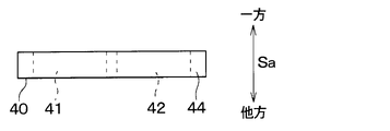
- the fixed valve 40 is supported from the other side in the axial direction Sa by the bottom portion 110 and the outer peripheral support portion 11b of the housing 10. As shown in FIGS. 11 and 12, the fixed valve 40 is formed in a plate shape whose thickness direction coincides with the axial direction Sa.
- the fixed valve 40 is a disc valve formed in a disk shape centered on the axis S.
- a sliding surface that slides with respect to the drive valve 30 is formed on one side of the fixed valve 40 in the axial direction Sa.
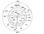
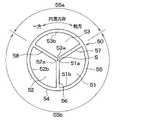
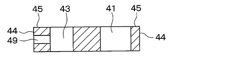
- the fixed valve 40 forms openings 41, 42, 43.
- the openings 41, 42, and 43 are each formed so as to penetrate in the axial direction Sa (that is, the thickness direction).
- the openings 41, 42, and 43 are arranged in the circumferential direction about the axis S, respectively.
- the opening 41 is arranged on the other side of the opening 43 in the circumferential direction about the axis S.
- the opening 42 is arranged on the other side of the opening 41 in the circumferential direction about the axis S.
- the opening 43 is arranged on the other side of the opening 42 in the circumferential direction about the axis S.
- the opening 41 is opened in a fan shape in the fixed valve 40, in which the apex 41a is arranged radially inside with the axis S as the center and the circumferential portion 41b is arranged radially outside with the axis S as the center. ing.
- the opening 42 is opened in a fan shape in the fixed valve 40, in which the apex 42a is arranged radially inside with the axis S as the center and the circumferential portion 42b is arranged radially outside with the axis S as the center. ing.
- the opening 43 is opened in a fan shape in the fixed valve 40, in which the apex 43a is arranged radially inside with the axis S as the center and the circumferential portion 43b is arranged radially outside with the axis S as the center. ing.
- the openings 41, 42, and 43 are formed independently of each other.
- the opening 41 communicates with the outlet port 13b through the downstream flow path 113 and the pipe flow path 13a of the outlet pipe 13, and constitutes a first fixed flow path through which cooling water flows.
- the opening 42 communicates with the outlet port 14b through the downstream flow path 114 and the pipe flow path 14a of the outlet pipe 14, and constitutes a second fixed flow path through which the cooling water flows.
- the opening 43 constitutes a through chamber, and is covered by the bottom 110 from the other side in the axial direction Sa.
- the opening 43 is covered from one side of the axial direction Sa by the lid 34 of the drive valve 30.
- the opening 43 communicates with the upstream flow path 112 of the cooling water flow path 111 through the communication opening 32.
- An outer peripheral surface 44 is continuously formed on the outer side of the fixed valve 40 in the radial direction centered on the axis S over the circumferential direction centered on the axis S.
- the outer peripheral surface 44 is formed so as to continuously cover the openings 41, 42, and 43 from the radial outside centered on the axis S.
- the fixed valve 40 includes an annular portion 45 and beam portions 46, 47, 48.
- the annular portion 45 is formed in an annular shape centered on the axis S so as to surround the openings 41, 42, and 43 from the radial outside centered on the axis S.
- the beam portions 46, 47, and 48 are each formed so as to extend in the radial direction about the axis S.
- the beam portions 46, 47, and 48 are arranged so as to be offset in the circumferential direction about the axis S, respectively.
- the beam portion 46 is arranged between the openings 41 and 42.
- the beam portion 47 is arranged between the openings 41 and 43.
- the beam portion 48 is arranged between the openings 43 and 42.
- the radial outside of the beam portion 46 centered on the axis S is connected to the annular portion 45.
- the radial outer side of the beam portion 47 centered on the axis S is connected to the annular portion 45.
- the radial outer side of the beam portion 48 centered on the axis S is connected to the annular portion 45.
- the radial inside of each of the beam portions 46, 47, and 48 about the axis S is connected.
- a fan shape is arranged on one side of the fixed valve 40 in the circumferential direction with respect to the opening 41 and on the other side in the circumferential direction with respect to the opening 42.
- the region 45a and the beam portion 46 are supported by the bottom portion 110 from the other side in the axial direction.
- the fan-shaped region 45a is a region of the annular portion 45 arranged on one side in the circumferential direction with respect to the opening 41 and on the other side in the circumferential direction with respect to the opening 42, and the beam portion 47. 48 and are included.
- the fan-shaped region 45b is supported by the outer peripheral support portion 11b.
- the bottom portion 110 is arranged on the other side of the axial direction Sa with respect to the upstream side flow path 112 in the housing main body 11.
- the bottom portion 110 is arranged so as to cover the upstream side flow path 112 from the other side in the axial direction Sa.
- the outer peripheral support portion 11b is formed so as to project radially inward about the axis S from the inner wall 11a of the housing main body 11.
- the gasket 50 is arranged on the other side of the axial direction Sa with respect to the fixed valve 40.
- the gasket 50 is arranged on one side of the axial direction Sa with respect to the bottom portion 110 and the outer peripheral support portion 11b of the housing main body 11.
- the gasket 50 is supported from the other side in the axial direction Sa by the bottom portion 110 and the outer peripheral support portion 11b of the housing 10. As shown in FIGS. 13 and 14, the gasket 50 is formed in a plate shape whose axis coincides with the axis S. Specifically, the gasket 50 is formed in a disk shape centered on the axis S.
- the gasket 50 forms openings 51, 52, 53.
- the openings 51, 52, and 53 are each formed so as to penetrate in the axial direction Sa.
- the openings 51, 52, and 53 are arranged in the circumferential direction about the axis S.
- the opening 51 is arranged on the other side of the opening 53 in the circumferential direction about the axis S.
- the opening 52 is arranged on the other side of the opening 51 in the circumferential direction about the axis S.
- the opening 53 is arranged on the other side of the opening 52 in the circumferential direction about the axis S.
- the opening 51 is arranged so as to overlap the opening 41 of the fixed valve 40 in the axial direction Sa.
- the opening 51 communicates with the opening 41 of the fixed valve 40.
- the opening 51 communicates with the outlet port 13b through the downstream flow path 113 and the pipe flow path 13a of the outlet pipe 13.
- the opening 51 is opened in the gasket 50 in a fan shape in which the apex 51a is arranged radially inside with the axis S as the center and the circumferential portion 51b is arranged radially outside with the axis S as the center. There is.
- the opening 52 is arranged so as to overlap the opening 42 of the fixed valve 40 in the axial direction Sa.
- the opening 52 communicates with the opening 42 of the fixed valve 40.
- the opening 52 communicates with the outlet port 14b through the downstream flow path 114 and the pipe flow path 14a of the outlet pipe 14.
- the opening 52 is opened in the gasket 50 in a fan shape in which the apex 52a is arranged radially inside with the axis S as the center and the circumferential portion 52b is arranged radially outside with the axis S as the center. There is.
- the opening 53 is arranged so as to overlap the opening 43 of the fixed valve 40 in the axial direction Sa.
- the opening 53 communicates with the opening 43 of the fixed valve 40.
- the opening 53 is covered by the bottom 110 from the other side in the axial direction Sa.
- the opening 53 is opened in the gasket 50 in a fan shape in which the apex 53a is arranged radially inside the axis S and the circumferential portion 53b is arranged radially outside the axis S. There is.
- An outer peripheral surface 54 is continuously formed on the outer side of the gasket 50 in the radial direction centered on the axis S over the circumferential direction centered on the axis S.
- the outer peripheral surface 54 is formed so as to continuously cover the openings 51, 52, and 53 from the radial outside centered on the axis S.
- the gasket 50 includes an annular portion 55 and beam portions 56, 57, 58.
- the annular portion 55 is formed in an annular shape centered on the axis S so as to surround the openings 51, 52, and 53 from the radial outside centered on the axis S.
- the beam portions 56, 57, and 58 are arranged in the circumferential direction about the axis S, respectively.
- the beam portions 56, 57, and 58 are each formed so as to extend in the radial direction about the axis S.
- the beam portion 56 is arranged between the openings 51 and 52.
- the beam portion 57 is arranged between the openings 51 and 53.
- the beam portion 58 is arranged between the openings 53 and 52.
- the radial outside of the beam portion 56 centered on the axis S is connected to the annular portion 55.
- the radial outer side of the beam portion 57 about the axis S is connected to the annular portion 55.
- the radial outer side of the beam portion 58 centered on the axis S is connected to the annular portion 55.
- the radial inside of each of the beam portions 56, 57, and 58 about the axis S is connected.
- the fan-shaped region 55a and the beam portion 56 arranged on one side in the circumferential direction with respect to the opening 51 and on the other side in the circumferential direction with respect to the opening 52 are axially oriented by the bottom portion 110. It is supported from the other side.
- the fan-shaped region 55a is a region of the ring portion 55 arranged on one side in the circumferential direction with respect to the opening 51 and on the other side in the circumferential direction with respect to the opening 52, and the beam portions 57, 58. And include.
- the fan-shaped region 55a is arranged so as to overlap the fan-shaped region 45a of the fixed valve 40 in the axial direction Sa.
- the beam portion 56 is arranged so as to overlap the beam portion 46 of the fixed valve 40 in the axial direction Sa.
- the fan-shaped region 55b is supported by the outer peripheral support portion 11b.
- the fan-shaped region 55b is arranged so as to overlap the fan-shaped region 45b of the fixed valve 40 in the axial direction Sa.
- the gasket 50 is pushed by the elastic force of the spring 60 and is compressed by elastic deformation between the outer peripheral support portion 11b and the bottom portion 110 of the housing 10 and the fixed valve 40.
- the gasket 50 seals between the bottom portion 110 and the outer peripheral support portion 11b and the fixed valve 40 as a sealing member.
- the gasket 50 seals between the opening forming portion 41c forming the opening 41 of the fixed valve 40, the bottom portion 110 of the housing 10, and the outer peripheral support portion 11b.
- the gasket 50 seals between the opening forming portion 42c forming the opening 42 of the fixed valve 40, the bottom portion 110 of the housing 10, and the outer peripheral support portion 11b.
- the gasket 50 seals between the bottom 110 and the outer peripheral support portion 11b of the housing 10 and the opening forming portion 43c of the fixed valve 40 that forms the opening 43.
- the gasket 50 is made of an elastic material such as rubber or resin that can be elastically deformed.
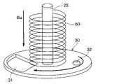
- the spring 60 is arranged in the upstream flow path 112 and is supported by the housing 23 of the actuator device 21. As a pressing member, the spring 60 generates an elastic force that presses the drive valve 30 against the other side in the axial direction Sa as shown by the arrow Ba in FIG.
- the spring 60 is composed of, for example, a compression spring, that is, a compression coil spring.
- 5 and 7 are views of the drive valve 30 in the housing 10 of the valve device according to the present embodiment as viewed from one side in the axial direction Sa.
- the drive shaft 22 and the spring 60 are not shown.
- the lid 34 of the drive valve 30 covers the opening 42 of the fixed valve 40, and the flow path opening 31 of the drive valve 30 communicates with the opening 41 of the fixed valve 40. Become a state.
- the cooling water flows into the pipe flow path 12a through the inlet port 12b of the inlet pipe 12. Along with this, the cooling water that has passed through the pipe flow path 12a flows into the upstream side flow path 112.
- the cooling water in the upstream side flow path 112 is downstream through the flow path opening 31 of the drive valve 30, the opening 41 of the fixed valve 40, and the opening 51 of the gasket 50, as shown by the arrow W1 in FIG. It flows into the side flow path 113.
- the cooling water has flowed into the inside of the opening 43 from the upstream flow path 112 through the communication opening 32.
- the electric motor 21a is controlled by the electronic control device 70 and outputs a rotational force to the drive valve 30 via the gear mechanism 21b. Then, the gear mechanism 21b rotates the drive valve 30 to the other side in the circumferential direction about the axis S.
- the lid 34 of the drive valve 30 covers the opening 41 of the fixed valve 40, and the flow path opening 31 of the drive valve 30 communicates with the opening 42 of the fixed valve 40. become.
- the cooling water flowing to the upstream flow path 112 through the inlet port 12b and the pipe flow path 12a of the inlet pipe 12 is the flow path opening 31, the opening 42, and the opening of the drive valve 30 as shown by the arrow W2 in FIG. It flows through the portion 52 to the downstream flow path 114.
- the cooling water in the downstream flow path 114 is discharged from the outlet port 14b through the pipe flow path 14a of the outlet pipe 14.
- the actuator device 21 rotates the drive valve 30 around the axis S through the drive shaft 22 so that the flow path opening 31 of the drive valve 30 communicates with each of the openings 41 and 42 of the fixed valve 40. Become.
- the cooling water in the upstream side flow path 112 flows to the downstream side flow path 113 through the flow path opening 31 of the drive valve 30, the opening 41 of the fixed valve 40, and the opening 51 of the gasket 50. Then, the cooling water in the downstream flow path 113 is discharged from the outlet port 13b through the pipe flow path 13a of the outlet pipe 13.
- the cooling water in the upstream side flow path 112 flows to the downstream side flow path 114 through the flow path opening 31 of the drive valve 30, the opening 42 of the fixed valve 40, and the opening 52 of the gasket 50. Then, the cooling water in the downstream flow path 114 is discharged from the outlet port 14b through the pipe flow path 14a of the outlet pipe 14.
- the cooling water in the upstream flow path 112 is discharged from the outlet port 13b of the outlet pipe 13 and the outlet port 14b of the outlet pipe 14.
- the actuator device 21 rotates the drive valve 30 through the drive shaft 22 to the other side in the circumferential direction about the axis S. Along with this, the area communicating between the flow path opening 31 and the opening 41 is reduced, while the area communicating between the flow path opening 31 and the opening 42 is increased.
- the actuator device 21 rotates the drive valve 30 through the drive shaft 22 to one side in the circumferential direction about the axis S. Along with this, the area of communication between the flow path opening 31 and the opening 41 is increased, while the area of communication between the flow path opening 31 and the opening 42 is decreased.
- the valve device includes a housing 10, a drive valve 30, a fixed valve 40, and a gasket 50.
- the housing 10 forms an inlet port 12b into which cooling water enters, a cooling water flow path 111 through which cooling water flowing in from the inlet port 12b flows, and outlet ports 13b and 14b for discharging fluid passing through the cooling water flow path 111, respectively. do.
- the fixed valve 40 forms openings 41, 42, 43 arranged in the circumferential direction about the axis S.
- the opening 41 constitutes a first flow path through which cooling water flows, and is an opening that communicates with the outlet port 13b.
- the opening 42 is an opening that communicates with the exit port 14b.
- the opening 43 constitutes a penetration chamber penetrating in the axial direction Sa.
- the drive valve 30 is formed so as to cover the openings 41, 42, and 43 of the fixed valve 40 in the cooling water flow path 111 from one side in the axial direction Sa.
- the drive valve 30 is configured to be freely rotatable about the axis S.
- the drive valve 30 forms a lid portion 34 that covers the flow path opening 31, the communication opening 32, and the openings 41, 42 forming the second flow path penetrating the axial direction Sa from one side of the axial direction Sa. ..
- the drive valve 30 is configured so that the flow path opening 31 communicates with at least one of the openings 41 and 42 by its rotation.
- the housing 10 is formed so as to cover the opening 43 of the fixed valve 40 from the other side of the axial direction Sa, and includes a bottom portion 110 that supports the fixed valve 40 from the other side of the axial direction Sa.
- the inlet port 12b and the outlet port 13b communicate with each other through the flow path opening 31 and the opening 41.
- the inlet port 12b and the outlet port 14b communicate with each other through the flow path opening 31 and the opening 42.
- the drive valve 30 forms a communication opening 32 that communicates the opening 43 of the fixed valve 40 and the upstream flow path 112.
- the communication opening 32 is formed so as to penetrate the drive valve 30 from the inside of the opening 41 in the axial direction Sa.
- the upstream side flow path 112 is arranged on the upstream side of the cooling water flow with respect to the drive valve 30 and the fixed valve 40 in the cooling water flow path 111.
- the opening 43 is a closed region sealed by the lid 34 of the fixed valve 40, the bottom 110 of the housing body 11, and the opening forming portion 43c of the fixed valve 40 forming the opening 43.
- the drive valve 30 forms a communication opening 32 for communicating the opening 43 of the fixed valve 40 and the upstream flow path 112 as described above.
- the drive valve 30 includes an outer peripheral surface 33 formed so as to cover the flow path opening 31 and the communication opening 32 from the radial outside centered on the axis S, and the outer peripheral surface 33 is centered on the axis S. It is continuously configured in the circumferential direction.
- the drive valve 30 is a ceramic disc valve manufactured by a firing step of firing a slurry.
- the slurry is a fluid containing a resin and a metal material, and is a raw material for ceramics.
- the drive valve 30 of the present embodiment is less likely to be distorted during the firing process as compared with the drive valve having the flow path opening 31 formed in a notch hole that opens radially outward around the axis S. Become.
- the drive valve 30 of the present embodiment is less likely to have variations in the position of the flow path opening 31 during the firing process of the slurry. Therefore, it is possible to control the flow rate of the fluid flowing through the openings 41 and 42 with high accuracy.
- the fixed valve 40 is a ceramic disc valve manufactured by a firing step of firing a slurry.
- the fixed valve 40 of the present embodiment is less likely to be distorted during the firing process as compared with the fixed valve having the openings 41 to 43 formed in the notch holes that open radially outward around the axis S. Become.
- the fixed valve 40 of the present embodiment is less likely to have variations in the positions of the openings 41, 42, and 43 during the firing process of the slurry. Therefore, it is possible to control the flow rate of the fluid flowing through the openings 41 and 42 with high accuracy.
- the spring 60 is arranged in the upstream side flow path 112, is supported by the housing 23 of the actuator device 21, and generates an elastic force that presses the drive valve 30 against the other side in the axial direction Sa by the elastic force.
- the elastic force of the spring 60 can apply a force from the drive valve 30 to the gasket 50 via the fixed valve 40. Therefore, the gasket 50 is compressed by elastic deformation between the bottom portion 110 and the outer peripheral support portion 11b of the housing body 11 and the fixed valve 40.
- the gasket 50 can improve the sealing property for sealing the bottom portion 110 and the outer peripheral support portion 11b of the housing body 11 and the fixed valve 40.
- the elastic force of the spring 60 makes it possible to appropriately bring the sliding surface of the drive valve 30 and the sliding surface of the fixed valve 40 into contact with each other.
- the spring 60 is a compression spring that is arranged on one side of the axial direction Sa with respect to the drive valve 30 and generates an elastic force that presses the drive valve 30 against the fixed valve 40.
- the gasket 50 seals between the fixed valve 40 and the bottom 110 of the housing body 11. Specifically, the gasket 50 seals between the opening forming portion 41c forming the opening 41 and the bottom 110 of the housing body 11 in the fixed valve 40.
- the gasket 50 seals between the opening forming portion 42c forming the opening 42 and the bottom 110 of the housing main body 11 in the fixed valve 40.
- the gasket 50 seals between the opening forming portion 43c forming the opening 43 and the bottom 110 of the housing body 11 in the fixed valve 40.
- a disc valve formed in a plate shape and formed so that the thickness direction coincides with the axial direction Sa is used. Therefore, the dimension of the axial direction Sa of the valve device can be reduced.
- a disc valve formed in a plate shape so that the thickness direction coincides with the axial direction Sa is used. Therefore, the dimension of the axial direction Sa of the valve device can be reduced.
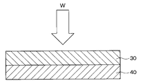
- the water pressure of the cooling water in the upstream side flow path 112 applies the drive valve 30 to the other side in the axial direction Sa as shown by the arrow W in FIG. Therefore, the gasket 50 is in a state of being compressed by elastic deformation between the outer peripheral support portion 11b and the bottom portion 110 of the housing 10 and the fixed valve 40 due to the water pressure applied from the drive valve 30 via the fixed valve 40. Therefore, the gasket 50 seals between the bottom portion 110 and the outer peripheral support portion 11b and the fixed valve 40.
- the spring 60A of the present embodiment includes a drive valve 30, a fixed valve 40, a spring body 61 penetrating the gasket 50, and a head portion 62 provided on one side of the axial direction Sa.
- the spring body 61 is configured in an elongated shape extending from the head 62 to the other side in the axial direction Sa.
- the head portion 62 is larger than the through hole through which the spring body 61 of the drive valve 30 penetrates.
- the other side of the spring body 61 in the axial direction Sa is fixed to the bottom 110 of the housing body 11.
- the spring 60A generates an elastic force by which the head portion 62 presses the drive valve 30 against the other side in the axial direction Sa as shown by the arrow Ga in FIG. 22 by the elastic force.
- elastic force is applied to the gasket 50 from the drive valve 30 via the fixed valve 40.
- the gasket 50 is compressed by elastic deformation between the bottom portion 110 and the outer peripheral support portion 11b of the housing body 11 and the fixed valve 40. Therefore, the gasket 50 can seal between the bottom portion 110 and the outer peripheral support portion 11b of the housing body 11 and the fixed valve 40.
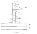
- the valve device to which the coil spring 80 is added in the valve device of the first embodiment will be described with reference to FIGS. 23 and 24.
- FIG. 23 shows a spring 60, a coil spring 80, and a drive shaft 22 arranged on one side of the axial direction Sa with respect to the drive valve 30 in the housing 10 of the valve device of the present embodiment.
- the coil spring 80 of the present embodiment is wound in a coil shape centered on the drive shaft 22 (that is, the axis S).
- the coil spring 80 is arranged radially outside the axis S with respect to the spring 60.
- One end 82 of the axial direction Sa of the coil spring 80 is fixed by the housing 23 of the actuator 20.
- the other end of the coil spring 80 in the axial direction Sa is fixed to the drive valve 30 by the fixing portion 81.
- the coil spring 80 is used in a state where the coil spring 80 undergoes elastic deformation (that is, torsional elastic deformation) twisted in the circumferential direction about the axis S.
- the coil spring 80 generates an urging force Ka that urges the drive valve 30 to one side in the circumferential direction due to the torsional elastic deformation of the coil spring 80.
- the coil spring 80 is an elastic member in which the urging force Ka is generated by the torsional elastic deformation of the coil spring 80. In this way, the coil spring 80 functions as a torsion spring.
- the urging force Ka of the coil spring 80 is transmitted as a rotational force in the order of the drive valve 30, the drive shaft 22, the gear mechanism 21b, and the electric motor 21a. Therefore, during the operation of the valve device, the electric motor 21a generates a reaction force against the urging force Fc of the coil spring 18 even when the electric motor 21a is not rotating.
- the electric motor 21a generates a reaction force against the urging force Ka of the coil spring 80 even when the electric motor 21a is not rotating.
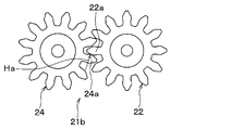
- the coil spring 80 has a pair of tooth portions that come into contact with each other at all the meshing points of the gears of the gear mechanism 21b by urging the drive valve 30 to one side in the circumferential direction as an urging member. Press one of the teeth against the other.
- the gear 24 is a gear that transmits the rotational force of the electric motor 21a to the drive shaft 22 by meshing with the drive shaft 22.
- the fixed valve 40 is configured to be in direct contact with the bottom portion 110 and the outer peripheral support portion 11b of the housing main body 11.
- the communication opening 32 of the drive valve 30 is formed so as to be covered by the outer peripheral surface 33 from the radial outside centered on the axis S.
- FIG. 26, FIG. 26, FIG. 27, FIG. 28, and FIG. 29 will be referred to and described.
- the communication opening 32 of the drive valve 30 of the present embodiment constitutes a notch hole that penetrates the axial direction Sa and is opened radially outward with the axis S as the center.
- the drive valve 30 forms a flow path opening 31 communicating with at least one of the openings 41 and 42 of the fixed valve 40, and a communication opening 32.
- the communication opening 32 communicates the opening 43 with the upstream flow path 112.
- the communication opening 32 of the drive valve 30 constitutes a notch hole that penetrates the axial direction Sa and is opened radially outward with the axis S as the center.
- the area of the sliding surface of the drive valve 30 is reduced as compared with the first embodiment in which the drive valve 30 is configured to cover the communication opening 32 from the radial outside centered on the axis S. Can be done. This makes it possible to reduce the frictional force between the drive valve 30 and the fixed valve 40.
- the communication opening 32 of the drive valve 30 constitutes a notch hole opened radially outward about the axis S. Therefore, as compared with the first embodiment, the material constituting the drive valve 30 can be reduced, so that the cost can be reduced.
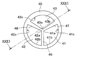
- 7th Embodiment In the first embodiment, an example in which the opening 43 of the fixed valve 40 and the upstream flow path 112 are communicated with each other by the communication opening 32 of the drive valve 30 has been described.
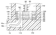
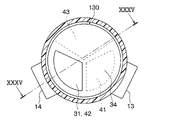
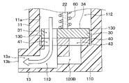
- FIGS. 30, 31, and FIGS. 30, show the seventh embodiment in which the opening 43 of the fixed valve 40 and the upstream flow path 112 are communicated with each other through the communication hole 49 of the fixed valve 40 and the gap 130. It will be described with reference to 32.
- the communication hole 49 is a penetrating communication portion in the annular portion 45 of the fixed valve 40 that penetrates radially outward from the opening 43 of the fixed valve 40 centered on the axis S.
- the ring portion 45 of the fixed valve 40 is formed so as to cover the communication hole 49 from one side and the other side in the axial direction Sa.
- the gap 130 is a gap communication portion formed in the circumferential direction about the axis S between the fixed valve 40 and the drive valve 30 and the inner wall 11a of the housing main body 11.
- the gap 130 communicates the communication hole 49 and the upstream flow path 112.
- the gap 130 together with the communication hole 49, constitutes a communication passage that communicates the opening 43 and the upstream flow path 112.
- the opening 43 of the fixed valve 40 and the upstream flow path 112 are communicated with each other through the communication hole 49 and the gap 130 of the fixed valve 40.
- the communication hole 49 penetrates the annular portion 45 of the fixed valve 40 from the opening 43 of the fixed valve 40 to the outside in the radial direction centered on the axis S.
- the ring portion 45 of the fixed valve 40 is formed so as to cover the communication hole 49 from one side and the other side in the axial direction Sa.
- the fixed valve 40 of the present embodiment is compared with a fixed valve constituting a notched hole in which the communication hole 49 penetrates in the axial direction Sa and is opened outward in the radial direction about the axis S. , Distortion during the firing process of the slurry is less likely to occur.
- the positions of the openings 41, 42, and 43 are less likely to vary. Therefore, it is possible to control the flow rate of the fluid flowing through the openings 41 and 42 with high accuracy.
- the opening 43 of the fixed valve 40 is formed so as to be covered by the outer peripheral surface 44 from the radial outside centered on the axis S.
- FIG. 34, and FIG. 35 will be referred to and described.
- the opening 43 of the fixed valve 40 of the present embodiment constitutes a through chamber and communicates with the upstream flow path 112 via the gap 130.
- the gap 130 is formed between the fixed valve 40 and the drive valve 30 and the inner wall 11a of the housing main body 11 in the circumferential direction about the axis S.
- the gap 130 communicates with the opening 43 and the upstream flow path 112.
- the opening 43 of the fixed valve 40 penetrates in the axial direction Sa, and constitutes a notch hole opened radially outward with the axis S as the center.
- the area of the sliding surface of the fixed valve 40 can be reduced as compared with the first embodiment using the fixed valve 40 configured to cover the opening 43 from the radial outside centered on the axis S. can. This makes it possible to reduce the frictional force between the drive valve 30 and the fixed valve 40.
- the opening 43 constitutes a notch hole opened radially outward about the axis S. Therefore, as compared with the first embodiment, the material constituting the fixed valve 40 can be reduced, so that the cost can be reduced.
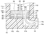
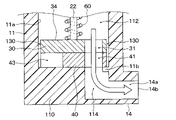
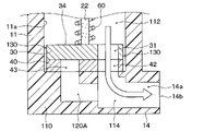
- the communication hole 120 of the housing 10 of the present embodiment is a through communication portion formed in the bottom portion 110 in the radial direction about the axis S.
- the communication hole 120 has an opening 121 that opens on one side of the axial direction Sa in the opening 43, and an opening 122 that opens on one side of the axial direction Sa in the gap 130.
- the communication hole 120 can communicate the inside of the opening 43 with the gap 130.
- the gap 130 is formed between the fixed valve 40 and the drive valve 30 and the inner wall 11a of the housing main body 11 in the circumferential direction with the axis S as the center.
- the gap 130 is an interval communication portion that allows the communication hole 120 and the upstream flow path 112 to communicate with each other.
- the bottom portion 110 is formed with a ceiling portion 120a that covers the communication hole 120 of the housing 10 from the other side in the axial direction Sa.
- the opening 121 is formed on the inner side in the radial direction about the axis S with respect to the ceiling portion 120a.
- the opening 122 is formed on the outer side in the radial direction about the axis S with respect to the ceiling portion 120a. Since the valve device of the present embodiment is provided with the communication hole 120 and the gap 130 instead of the communication opening 32 in the valve device of the first embodiment, the configuration other than the communication hole 120 and the gap 130 is provided. The explanation is omitted.
- the opening 43 of the fixed valve 40 and the upstream flow path 112 are communicated with each other through the communication hole 120 and the gap 130 of the housing 10.
- a valve device in which the closed region is eliminated between the bottom portion 110 of the housing 10 and the drive valve 30, as in the first embodiment.
- a ceiling portion 120a is formed so as to cover the communication hole 120 of the housing 10 that communicates the opening 43 of the fixed valve 40 and the upstream flow path 112 from the other side in the axial direction Sa. bottom.
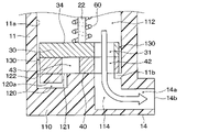
- the communication hole 120 of the housing 10 has a gap 130 and an opening 121 that opens on one side of the axial direction Sa in the opening 43 at the bottom 110.
- the ceiling portion 120a that covers the communication hole 120 from the other side in the axial direction Sa is not formed. Therefore, the communication hole 120 is opened on one side of the axial direction Sa at the bottom 110 of the housing 10. That is, the communication hole 120 constitutes a notch hole opened on one side of the axial direction Sa at the bottom 110 of the housing 10.
- the gap 130 is formed between the fixed valve 40 and the drive valve 30 and the inner wall 11a of the housing main body 11 in the circumferential direction with the axis S as the center.
- the gap 130 is an interval communication portion that allows the communication hole 120 and the upstream flow path 112 to communicate with each other.
- the opening 43 of the fixed valve 40 and the upstream flow path 112 are communicated with each other through the communication hole 120 and the gap 130 of the housing 10.
- the inside of the opening 43 of the fixed valve 40 and the upstream flow path 112 are the communication hole 120 and the gap 130 of the housing 10. It is communicated through.
- the communication hole 120A is provided at the bottom 110 of the housing 10 in place of the communication hole 120.
- the communication hole 120A communicates only one of the downstream flow paths 113 and 114 with the downstream flow path 114 and the opening 43.
- the downstream side flow path 114 is the first downstream side flow path of the cooling water flow path 111, which is arranged on the downstream side of the cooling water flow with respect to the drive valve 30 and the fixed valve 40.
- the downstream flow paths 113 and 114 are independently provided at the bottom 110 of the housing 10.
- valve device of the present embodiment and the valve device of the ninth embodiment have the same configurations other than the communication holes 120A and 120, the description of the other configurations will be omitted. As described above, it is possible to provide a valve device in which the closed region is eliminated between the bottom portion 110 of the housing 10 and the drive valve 30, as in the first embodiment.
- the communication hole 120B is provided in place of the communication hole 120A of the eleventh embodiment.
- the communication hole 120B communicates only one of the downstream flow paths 113 and 114 with the downstream flow path 113 and the opening 43.
- the downstream side flow path 113 is a second downstream side flow path arranged on the downstream side of the cooling water flow with respect to the drive valve 30 and the fixed valve 40 in the cooling water flow path 111.
- valve device of the present embodiment and the valve device of the eleventh embodiment have the same configurations other than the communication holes 120A and 120B, the description of the other configurations will be omitted. As described above, it is possible to provide a valve device in which the closed region is eliminated between the bottom portion 110 of the housing 10 and the drive valve 30, as in the eleventh embodiment.
- cooling water used as the fluid to be circulated in the valve device
- the fluid to be circulated in the valve device is other than the cooling water.
- Other fluids may be used.
- a liquid other than cooling water or a gas may be used as the other fluid.
- Other elastic members include various springs such as tension springs, torsion coil springs, thin leaf springs, conical springs, spiral springs, balance springs, and bond wire springs.
- the drive valve 30 and the fixed valve 40 are each made of ceramic, but instead, the drive valve 30 and the fixed valve 40 are made of resin materials, respectively. It may be composed of.
- the housing 10 is made of a resin material, but instead, the housing 10 may be made of a metal material or ceramic. ..
- the coil spring 80 that generates the urging force Ka that urges the drive valve 30 to one side in the circumferential direction by the torsional elastic deformation and the spring that presses the drive valve 30 to the other side in the axial direction Sa.
- An example in which 60 is provided has been described.
- one coil spring is an elastic member that presses the drive valve 30 against the other side in the axial direction Sa while generating an urging force Ka that urges the drive valve 30 to one side in the circumferential direction by torsional elastic deformation. It may be configured by.
- each of the above embodiments is not unrelated to each other, and can be appropriately combined unless the combination is clearly impossible.
- the second embodiment and the first, third to twelfth embodiments can be combined, and the third embodiment and the first, second, fourth to twelfth embodiments can be combined. It is possible to combine.
- the fourth embodiment and the first to third and fifth to twelfth embodiments can be combined, and the fifth embodiment and the first to fourth and sixth to twelfth embodiments can be combined. Can be combined.
- the sixth embodiment and the first to fifth and seventh to twelfth embodiments can be combined, and the seventh embodiment and the first to sixth and eighth to twelfth embodiments can be combined. Can be combined.
- the eighth embodiment and the first to seventh and ninth to twelfth embodiments can be combined, and the ninth embodiment and the first to eighth and tenth to twelfth embodiments can be combined. Can be combined.
- the tenth embodiment and the first to ninth, eleventh, and twelfth embodiments can be combined, and the eleventh embodiment and the first to tenth embodiments can be combined. be. It is possible to combine the twelfth embodiment and the first to tenth embodiments.
- the sensor when it is described that the external environment information of the vehicle (for example, the humidity outside the vehicle) is acquired from the sensor, the sensor is abolished and the external environment information is obtained from the server or cloud outside the vehicle. It is also possible to receive. Alternatively, it is also possible to abolish the sensor, acquire related information related to the external environmental information from a server or cloud outside the vehicle, and estimate the external environmental information from the acquired related information.
- the external environment information of the vehicle for example, the humidity outside the vehicle
- the sensor is abolished and the external environment information is obtained from the server or cloud outside the vehicle. It is also possible to receive.
- it is also possible to abolish the sensor acquire related information related to the external environmental information from a server or cloud outside the vehicle, and estimate the external environmental information from the acquired related information.
Landscapes
- Engineering & Computer Science (AREA)
- General Engineering & Computer Science (AREA)
- Mechanical Engineering (AREA)
- Multiple-Way Valves (AREA)
- Sliding Valves (AREA)
- Details Of Valves (AREA)
Priority Applications (3)
| Application Number | Priority Date | Filing Date | Title |
|---|---|---|---|
| CN202180068145.3A CN116324241A (zh) | 2020-10-06 | 2021-09-24 | 阀装置 |
| DE112021005297.7T DE112021005297T5 (de) | 2020-10-06 | 2021-09-24 | Ventilvorrichtung |
| US18/295,401 US12209671B2 (en) | 2020-10-06 | 2023-04-04 | Valve device |
Applications Claiming Priority (2)
| Application Number | Priority Date | Filing Date | Title |
|---|---|---|---|
| JP2020-169239 | 2020-10-06 | ||
| JP2020169239A JP7380505B2 (ja) | 2020-10-06 | 2020-10-06 | バルブ装置 |
Related Child Applications (1)
| Application Number | Title | Priority Date | Filing Date |
|---|---|---|---|
| US18/295,401 Continuation US12209671B2 (en) | 2020-10-06 | 2023-04-04 | Valve device |
Publications (1)
| Publication Number | Publication Date |
|---|---|
| WO2022075086A1 true WO2022075086A1 (ja) | 2022-04-14 |
Family
ID=81126748
Family Applications (1)
| Application Number | Title | Priority Date | Filing Date |
|---|---|---|---|
| PCT/JP2021/035042 Ceased WO2022075086A1 (ja) | 2020-10-06 | 2021-09-24 | バルブ装置 |
Country Status (5)
| Country | Link |
|---|---|
| US (1) | US12209671B2 (enExample) |
| JP (1) | JP7380505B2 (enExample) |
| CN (1) | CN116324241A (enExample) |
| DE (1) | DE112021005297T5 (enExample) |
| WO (1) | WO2022075086A1 (enExample) |
Families Citing this family (1)
| Publication number | Priority date | Publication date | Assignee | Title |
|---|---|---|---|---|
| WO2025205355A1 (ja) * | 2024-03-26 | 2025-10-02 | 株式会社デンソー | バルブ装置 |
Citations (2)
| Publication number | Priority date | Publication date | Assignee | Title |
|---|---|---|---|---|
| JP2018040384A (ja) * | 2016-09-05 | 2018-03-15 | 日本電産サンキョー株式会社 | バルブ装置 |
| US20190301619A1 (en) * | 2016-06-08 | 2019-10-03 | Hangzhou Sanhua Research Institute Co., Ltd. | Flow control device and method for manufacturing the same |
Family Cites Families (6)
| Publication number | Priority date | Publication date | Assignee | Title |
|---|---|---|---|---|
| DE3934976A1 (de) * | 1989-10-20 | 1991-04-25 | Grohe Armaturen Friedrich | Absperr- und regulierventil |
| US5127438A (en) * | 1990-04-19 | 1992-07-07 | Williams Richard T | Long lasting faucet having minimum wear |
| KR100670931B1 (ko) * | 2004-12-29 | 2007-01-19 | 김종구 | 수도 밸브 |
| JP5475861B2 (ja) * | 2009-03-17 | 2014-04-16 | ダンフォス アクチ−セルスカブ | 蒸気圧縮システム用の弁 |
| JP7255299B2 (ja) | 2019-04-01 | 2023-04-11 | 横浜ゴム株式会社 | ゴム組成物およびそれを用いたスタッドレスタイヤ |
| US12214326B2 (en) * | 2019-08-19 | 2025-02-04 | Delaware Capital Formation, Inc. | Chemical dispenser having a motorized rotary diverter valve and method of using same |
-
2020
- 2020-10-06 JP JP2020169239A patent/JP7380505B2/ja active Active
-
2021
- 2021-09-24 DE DE112021005297.7T patent/DE112021005297T5/de active Pending
- 2021-09-24 WO PCT/JP2021/035042 patent/WO2022075086A1/ja not_active Ceased
- 2021-09-24 CN CN202180068145.3A patent/CN116324241A/zh active Pending
-
2023
- 2023-04-04 US US18/295,401 patent/US12209671B2/en active Active
Patent Citations (2)
| Publication number | Priority date | Publication date | Assignee | Title |
|---|---|---|---|---|
| US20190301619A1 (en) * | 2016-06-08 | 2019-10-03 | Hangzhou Sanhua Research Institute Co., Ltd. | Flow control device and method for manufacturing the same |
| JP2018040384A (ja) * | 2016-09-05 | 2018-03-15 | 日本電産サンキョー株式会社 | バルブ装置 |
Also Published As
| Publication number | Publication date |
|---|---|
| DE112021005297T5 (de) | 2023-08-31 |
| CN116324241A (zh) | 2023-06-23 |
| JP7380505B2 (ja) | 2023-11-15 |
| US12209671B2 (en) | 2025-01-28 |
| US20230243432A1 (en) | 2023-08-03 |
| JP2022061314A (ja) | 2022-04-18 |
Similar Documents
| Publication | Publication Date | Title |
|---|---|---|
| WO2022075086A1 (ja) | バルブ装置 | |
| JP6531641B2 (ja) | 弁開閉時期制御装置 | |
| KR102658775B1 (ko) | 토크 컨버터 클러치 어셈블리 | |
| CN109312871B (zh) | 流路切换阀 | |
| CN107379007A (zh) | 关节结构 | |
| CN110886873A (zh) | 流体无交叉切换阀 | |
| WO2014069361A1 (ja) | バルブ装置 | |
| JP6787806B2 (ja) | 操作器 | |
| JP5762170B2 (ja) | 回転ダンパ | |
| JP2017180639A (ja) | シール構造及び電動弁 | |
| JP2010261564A (ja) | ロータリー弁及びその生産方法 | |
| JP5329881B2 (ja) | 軸方向スラスト除荷装置 | |
| JP2008261433A (ja) | 弁体開閉装置 | |
| JP2008261432A (ja) | 弁体開閉装置 | |
| JP5611662B2 (ja) | 多方切換弁 | |
| JP4982449B2 (ja) | ロータリーダンパ | |
| JP5029100B2 (ja) | 自動変速機 | |
| JP7271349B2 (ja) | 回転抵抗装置および電子装置 | |
| JP2018011448A (ja) | アクチュエータ | |
| JP2017210977A (ja) | 二重偏心弁及びその製造方法 | |
| CN114096772A (zh) | 流路切换阀 | |
| JP2000345979A (ja) | スクロール型流体機械 | |
| WO2020075370A1 (ja) | 可変容量機構、及び、過給機 | |
| JP2008223959A (ja) | 流体圧アクチュエータ | |
| JP4904824B2 (ja) | 自動変速機の回転数検出装置 |
Legal Events
| Date | Code | Title | Description |
|---|---|---|---|
| 121 | Ep: the epo has been informed by wipo that ep was designated in this application |
Ref document number: 21877387 Country of ref document: EP Kind code of ref document: A1 |
|
| 122 | Ep: pct application non-entry in european phase |
Ref document number: 21877387 Country of ref document: EP Kind code of ref document: A1 |