WO2022075038A1 - 多孔質金属体の製造方法及び、多孔質金属体 - Google Patents
多孔質金属体の製造方法及び、多孔質金属体 Download PDFInfo
- Publication number
- WO2022075038A1 WO2022075038A1 PCT/JP2021/034169 JP2021034169W WO2022075038A1 WO 2022075038 A1 WO2022075038 A1 WO 2022075038A1 JP 2021034169 W JP2021034169 W JP 2021034169W WO 2022075038 A1 WO2022075038 A1 WO 2022075038A1
- Authority
- WO
- WIPO (PCT)
- Prior art keywords
- titanium
- porous metal
- metal body
- powder
- containing powder
- Prior art date
- Legal status (The legal status is an assumption and is not a legal conclusion. Google has not performed a legal analysis and makes no representation as to the accuracy of the status listed.)
- Ceased
Links
Images





Classifications
-
- B—PERFORMING OPERATIONS; TRANSPORTING
- B22—CASTING; POWDER METALLURGY
- B22F—WORKING METALLIC POWDER; MANUFACTURE OF ARTICLES FROM METALLIC POWDER; MAKING METALLIC POWDER; APPARATUS OR DEVICES SPECIALLY ADAPTED FOR METALLIC POWDER
- B22F3/00—Manufacture of workpieces or articles from metallic powder characterised by the manner of compacting or sintering; Apparatus specially adapted therefor ; Presses and furnaces
- B22F3/10—Sintering only
- B22F3/11—Making porous workpieces or articles
-
- C—CHEMISTRY; METALLURGY
- C22—METALLURGY; FERROUS OR NON-FERROUS ALLOYS; TREATMENT OF ALLOYS OR NON-FERROUS METALS
- C22C—ALLOYS
- C22C1/00—Making non-ferrous alloys
- C22C1/04—Making non-ferrous alloys by powder metallurgy
- C22C1/045—Alloys based on refractory metals
- C22C1/0458—Alloys based on titanium, zirconium or hafnium
-
- B—PERFORMING OPERATIONS; TRANSPORTING
- B22—CASTING; POWDER METALLURGY
- B22F—WORKING METALLIC POWDER; MANUFACTURE OF ARTICLES FROM METALLIC POWDER; MAKING METALLIC POWDER; APPARATUS OR DEVICES SPECIALLY ADAPTED FOR METALLIC POWDER
- B22F3/00—Manufacture of workpieces or articles from metallic powder characterised by the manner of compacting or sintering; Apparatus specially adapted therefor ; Presses and furnaces
- B22F3/004—Filling molds with powder
-
- B—PERFORMING OPERATIONS; TRANSPORTING
- B22—CASTING; POWDER METALLURGY
- B22F—WORKING METALLIC POWDER; MANUFACTURE OF ARTICLES FROM METALLIC POWDER; MAKING METALLIC POWDER; APPARATUS OR DEVICES SPECIALLY ADAPTED FOR METALLIC POWDER
- B22F3/00—Manufacture of workpieces or articles from metallic powder characterised by the manner of compacting or sintering; Apparatus specially adapted therefor ; Presses and furnaces
- B22F3/10—Sintering only
-
- B—PERFORMING OPERATIONS; TRANSPORTING
- B22—CASTING; POWDER METALLURGY
- B22F—WORKING METALLIC POWDER; MANUFACTURE OF ARTICLES FROM METALLIC POWDER; MAKING METALLIC POWDER; APPARATUS OR DEVICES SPECIALLY ADAPTED FOR METALLIC POWDER
- B22F5/00—Manufacture of workpieces or articles from metallic powder characterised by the special shape of the product
- B22F5/006—Manufacture of workpieces or articles from metallic powder characterised by the special shape of the product of flat products, e.g. sheets
-
- C—CHEMISTRY; METALLURGY
- C22—METALLURGY; FERROUS OR NON-FERROUS ALLOYS; TREATMENT OF ALLOYS OR NON-FERROUS METALS
- C22C—ALLOYS
- C22C1/00—Making non-ferrous alloys
- C22C1/08—Alloys with open or closed pores
-
- C—CHEMISTRY; METALLURGY
- C22—METALLURGY; FERROUS OR NON-FERROUS ALLOYS; TREATMENT OF ALLOYS OR NON-FERROUS METALS
- C22C—ALLOYS
- C22C14/00—Alloys based on titanium
-
- B—PERFORMING OPERATIONS; TRANSPORTING
- B22—CASTING; POWDER METALLURGY
- B22F—WORKING METALLIC POWDER; MANUFACTURE OF ARTICLES FROM METALLIC POWDER; MAKING METALLIC POWDER; APPARATUS OR DEVICES SPECIALLY ADAPTED FOR METALLIC POWDER
- B22F2998/00—Supplementary information concerning processes or compositions relating to powder metallurgy
- B22F2998/10—Processes characterised by the sequence of their steps
-
- B—PERFORMING OPERATIONS; TRANSPORTING
- B22—CASTING; POWDER METALLURGY
- B22F—WORKING METALLIC POWDER; MANUFACTURE OF ARTICLES FROM METALLIC POWDER; MAKING METALLIC POWDER; APPARATUS OR DEVICES SPECIALLY ADAPTED FOR METALLIC POWDER
- B22F3/00—Manufacture of workpieces or articles from metallic powder characterised by the manner of compacting or sintering; Apparatus specially adapted therefor ; Presses and furnaces
- B22F3/10—Sintering only
- B22F3/11—Making porous workpieces or articles
- B22F3/1121—Making porous workpieces or articles by using decomposable, meltable or sublimatable fillers
- B22F3/1125—Making porous workpieces or articles by using decomposable, meltable or sublimatable fillers involving a foaming process
-
- Y—GENERAL TAGGING OF NEW TECHNOLOGICAL DEVELOPMENTS; GENERAL TAGGING OF CROSS-SECTIONAL TECHNOLOGIES SPANNING OVER SEVERAL SECTIONS OF THE IPC; TECHNICAL SUBJECTS COVERED BY FORMER USPC CROSS-REFERENCE ART COLLECTIONS [XRACs] AND DIGESTS
- Y02—TECHNOLOGIES OR APPLICATIONS FOR MITIGATION OR ADAPTATION AGAINST CLIMATE CHANGE
- Y02E—REDUCTION OF GREENHOUSE GAS [GHG] EMISSIONS, RELATED TO ENERGY GENERATION, TRANSMISSION OR DISTRIBUTION
- Y02E10/00—Energy generation through renewable energy sources
- Y02E10/50—Photovoltaic [PV] energy
- Y02E10/542—Dye sensitized solar cells
-
- Y—GENERAL TAGGING OF NEW TECHNOLOGICAL DEVELOPMENTS; GENERAL TAGGING OF CROSS-SECTIONAL TECHNOLOGIES SPANNING OVER SEVERAL SECTIONS OF THE IPC; TECHNICAL SUBJECTS COVERED BY FORMER USPC CROSS-REFERENCE ART COLLECTIONS [XRACs] AND DIGESTS
- Y02—TECHNOLOGIES OR APPLICATIONS FOR MITIGATION OR ADAPTATION AGAINST CLIMATE CHANGE
- Y02P—CLIMATE CHANGE MITIGATION TECHNOLOGIES IN THE PRODUCTION OR PROCESSING OF GOODS
- Y02P70/00—Climate change mitigation technologies in the production process for final industrial or consumer products
- Y02P70/50—Manufacturing or production processes characterised by the final manufactured product
Definitions
- the present invention relates to a method for producing a sheet-shaped porous metal body containing titanium and a porous metal body.
- Titanium and titanium alloys are known to be materials with excellent corrosion resistance due to the formation of a passivation film on the surface. Taking advantage of such high corrosion resistance, it is expected that titanium or a titanium alloy will be used, for example, as a porous conductive material that is used in an environment where it can be corroded and requires required air permeability or liquid permeability. ..
- Patent Document 1 states that "it is used as a feeder in a solid polymer type water electrolytic cell or a current collector in a solid polymer fuel cell, and is used as a firing of spherical gas atomized titanium powder.
- Patent Document 1 states that "First, as shown in FIG. 1, spherical gas atomized titanium powder 1 having a predetermined particle size is not placed in a sintered container 2 made of high-density alumina. The inner shape of the sintered container 2 is a thin plate shape corresponding to the shape of the porous conductive plate to be manufactured. Next, the spherical gas atomized titanium powder 1 filled in the sintered container 2 is absent. Vacuum sintering by pressurization. "
- Patent Document 2 "a thickness of 5 ⁇ m to 60 ⁇ m, a porosity of 1% to 80%, a large number of isotropically communicated through holes, and a gradual change in the diameter of the mandrel in a cylindrical mandrel test".
- a dye-sensitized solar cell current collector made of a porous sintered metal thin film that does not crack on the outer surface of the bent portion up to a diameter of 6 mm when bent instead of a smaller one, "(a) below.
- a method for producing a current collector material for a dye-sensitized solar cell which comprises the steps (b), (c) and (d).
- a titanium-containing powder is spread dry on the molding surface of a molding die and deposited to a predetermined thickness, and the titanium-containing powder is heated. May be sintered. Thereby, a porous metal body can be obtained as a sintered body of the titanium-containing powder.
- the strength of the porous metal body which is a sintered body
- the sintered body firmly adheres to the molding die.
- the sintered body is liable to crack when the sintered body is peeled from the molding die. This cracking problem is more likely to occur as the sintered body becomes thinner.
- a mold release layer that facilitates peeling of the porous metal body from the molding die after sintering is formed in advance over the entire molding surface of the molding die. It was found that waviness can occur in the sheet-like porous metal body obtained after sintering. This problem of swell is also more likely to become apparent as the sintered body is thinner to some extent.
- the release layer is not formed in the region located on the outer edge side of the molding surface so that the titanium-containing powder in the process of sintering is fixed on the outer edge side of the molding surface, so that the powder is in contact with the release layer. It is presumed that the random shrinkage of the titanium-containing powder is suppressed, and as a result, the sintered body is maintained in a flatter shape.
- the present invention is not limited to such a theory.
- the method for producing a porous metal body of the present invention is a method for producing a sheet-shaped porous metal body containing titanium by heating and sintering a titanium-containing powder on the molding surface of a molding die.
- an adhesive region where the titanium-containing powder adheres at the time of sintering, which is located on the outer edge side of the molding surface and the release layer does not exist, and an easily peelable region where the release layer is formed are set.
- the powder deposition step of dry-depositing the titanium-containing powder on the molding surface after the region setting step, and the powder deposition step the titanium-containing powder is deposited on the molding surface at 950 ° C. It includes a powder sintering step of sintering the titanium-containing powder on the molding surface while heating to the above temperature and adhering the titanium-containing powder located on the bonding region to the bonding region.
- the average circularity of the titanium-containing powder is preferably 0.93 or less.
- the mold release layer can be formed with a mold release agent containing boron nitride and / or titanium borohydride.
- the 90% particle size D90 of the titanium-containing powder is 15 ⁇ m to 50 ⁇ m.
- the titanium content of the titanium-containing powder may be 75% by mass or more.
- the porous metal body of the present invention contains titanium, has a sheet shape having a thickness of 0.2 mm to 1.0 mm, has a porosity of 20% to 65%, and has a bending strength of 190 MPa or more. Is.
- the porous metal body of the present invention may have a titanium content of 75% by mass or more.
- the maximum height is 3 times or less of the thickness, or when the thickness of the porous metal body is less than 0.5 mm, the above.
- the maximum height is preferably 1.5 mm or less.
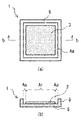
- FIG. 1 (a) is a plan view showing an example of a molding mold that can be used in the method for producing a porous metal body according to an embodiment of the present invention
- FIG. 1 (b) is a plan view showing FIG. 1 (a).
- 2 (a) is a plan view showing the mold of FIG. 1 in a state where a release layer is formed on the easily peelable region of the molded surface
- FIG. 2 (b) is a plan view of FIG. 2 (a).
- It is sectional drawing which follows the bb line. 3 (a) is a plan view showing the molding die and the mold release layer of FIG. 2 together with the titanium-containing powder deposited on the molding surface
- FIG. 3 (a) is a plan view showing the molding die and the mold release layer of FIG. 2 together with the titanium-containing powder deposited on the molding surface
- FIG. 3 (a) is a plan view showing the molding die and the mold release layer of FIG.
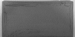
- FIG. 3 (b) is a plan view showing b- of FIG. 3 (a). It is sectional drawing which follows the b line. 4 (a) is a cross-sectional view showing a porous metal body manufactured according to FIGS. 1 to 3, and FIG. 4 (b) is a cross-sectional view taken along line bb of FIG. 4 (a). It is a side view of the porous metal body arranged on a plane which shows the evaluation method of the waviness of a porous metal body. It is a photograph which shows the porous metal body of the comparative example 1. FIG. It is a photograph which shows the porous metal body of the comparative example 2. It is a photograph which shows the porous metal body of the comparative example 3. It is a photograph which shows the porous metal body of the comparative example 5.
- the titanium-containing powder 4 is heated and sintered on the molding surface 2 of a molding die 1 such as a setter as illustrated in FIGS. 1 to 3. , A sheet-shaped porous metal body 4a containing titanium as shown in FIG. 4 is manufactured.
- the bonding region where the titanium-containing powder 4 adheres at the time of sintering without the release layer 3 located on the outer edge side of the molding surface 2 on the molding surface 2 of the molding mold 1 is present.
- a region setting step for setting Aa and an easily peelable region Ar on which the release layer 3 is formed a powder deposition step for dryly depositing the titanium-containing powder 4 on the molding surface 2 after the region setting step, and a powder.
- the titanium-containing powder 4 is heated to a temperature of 950 ° C. or higher on the molding surface 2, and the titanium-containing powder 4 located on the bonding region Aa is adhered to the bonding region Aa while being adhered to the bonding region Aa.
- the reference numerals may be omitted when they are not important.
- the titanium-containing powder can be various powders as long as it contains titanium.
- pure titanium powder and / or titanium alloy powder can be used as the titanium-containing powder. That is, as the titanium-containing powder, only pure titanium powder can be used, one or more types of titanium alloy powder can be used, or these pure titanium powder and titanium alloy powder can be combined. May be used.
- alloy element powders such as aluminum, vanadium and iron can also be used.
- Pure titanium powder has a titanium content of 95% by mass or more. That is, pure titanium powder means a powder consisting substantially only of titanium.
- pure titanium powder hydrogenated dehydrogenated titanium powder (so-called HDH titanium powder) obtained by hydrogenating and crushing sponge titanium or the like and then dehydrogenating, or dehydrogenation was not performed after the above crushing. Examples include titanium hydride powder.
- the hydrogenated titanium powder which is a pure titanium powder, allows a hydrogen content of up to 5% by mass.
- the titanium alloy powder described above is a powder containing titanium and alloying elements.
- the titanium alloy of the titanium alloy powder is, for example, an alloy of titanium and a metal (alloy element) such as Fe, Sn, Cr, Al, V, Mn, Zr, and Mo, and a specific example is Ti-6-.
- Ti-6Al-4V Ti-5Al-1Fe, Ti-5Al-2.5Sn, Ti-8-1-1 (Ti-8Al-1Mo-1V), Ti-6-2-4-2 ( Ti-6Al-2Sn-4Zr-2Mo-0.1Si), Ti-6-6-2 (Ti-6Al-6V-2Sn-0.7Fe-0.7Cu), Ti-6-2-4-6 (Ti-6-2-4-6) Ti-6Al-2Sn-4Zr-6Mo), SP700 (Ti-4.5Al-3V-2Fe-2Mo), Ti-17 (Ti-5Al-2Sn-2Zr-4Mo-4Cr), ⁇ -CEZ (Ti-5Al) -2Sn-4Zr-4Mo-2Cr-1Fe), TIMETAL555, Ti-553 (Ti-5Al-5Mo-5V-3Cr-0.5Fe), TIMETAL21S (Ti-15Mo-2.7Nb-3Al-0.2Si), TIMETAL LCB (Ti-4.5Fe-6.8Mo-1.5
- the alloying elements of the titanium alloy may contain Pd, Pt, Au, Ta, Nb, Ni, Ru and the like.
- the number added before each metal element represents the content (mass%) of the metal element.
- Ti-6Al-4V means a titanium alloy containing 6% by mass of Al and 4% by mass of V as alloying elements.
- the average circularity of the titanium-containing powder is not particularly limited, but is preferably 0.93 or less. Since the titanium-containing powder having an average circularity of 0.93 or less is available at a relatively low price, it is advantageous from the viewpoint of reducing the manufacturing cost.
- the average circularity of the titanium-containing powder is preferably 0.91 or less, more preferably 0.89 or less.
- the average circularity of the titanium-containing powder may be, for example, 0.50 or more, and further may be 0.60 or more. Since the above-mentioned HDH titanium powder and hydrogenated titanium powder are obtained by pulverization, the average circularity tends to be relatively small. On the other hand, the atomized powder produced by gas atomizing or the like often has an average circularity closer to 1.00 than the HDH titanium powder or the like.
- the average circularity of the titanium-containing powder is calculated as follows. Using an electron microscope, the circumference (A) of the projected area of the particles of the titanium-containing powder is measured, and the ratio to the circumference (B) of the circle having the same area as the projected area is defined as the circularity (B / A). do.
- the average circularity is the above-mentioned circularity (B / A) for each particle from 1000 to 1500 individual particle images by flowing particles together with the carrier liquid in the cell and taking an image of a large amount of particles with a CCD camera. Is calculated and calculated as the average value of the circularity of each particle.
- the value of the circularity becomes larger as the shape of the particle is closer to the true sphere, and the circularity of the particle having the shape of a perfect sphere is 1.00. Conversely, the circularity value decreases as the shape of the particle moves away from the true sphere.
- the titanium-containing powder can be only pure titanium powder.
- the titanium-containing powder can be a titanium alloy powder containing titanium and an alloying element.
- One or more of these powders are appropriately selected according to the composition of the porous metal body to be produced and the like.
- the titanium content of the titanium-containing powder is preferably 75% by mass or more.
- the titanium content can also be 95% by mass or more.
- the 90% particle size D90 of the titanium-containing powder is, for example, 15 ⁇ m to 90 ⁇ m, preferably 15 ⁇ m to 50 ⁇ m.
- the 90% particle size D90 means the particle size D90 of the particle size distribution (volume basis) obtained by the laser diffraction / scattering method.
- the mold release layer 3 is formed in a predetermined region of the molding surface 2 of the molding die 1 prior to depositing the titanium-containing powder 4 on the molding surface 2 of the molding die 1 in the powder deposition step described later. ..
- the release layer 3 By forming the release layer 3, the adhesion between the titanium-containing powder 4 and the molding die 1 at the time of sintering is well suppressed, and even if the thinly deposited titanium-containing powder 4 is sintered at a relatively high temperature, it can be sintered. After sintering, the porous metal body 4a can be easily taken out from the molding surface 2 of the molding die 1.
- the sheet-like porous metal body which is a sintered body of the titanium-containing powder, has an undulating shape, a wavy shape, or the like, and has undulations.
- the molding surface 2 is formed in a surface region located on the outer edge side of the molding surface 2.
- the adhesive region Aa where the release layer 3 is not formed so that the titanium-containing powder 4 adheres at the time of sintering and the easily peelable region Ar where the release layer 3 is formed in the surface region other than the adhesive region Aa. Divide and set each area. That is, here, the mold release layer does not exist in the adhesive region Aa on the outer edge side of the molded surface 2, and the mold release layer exists in the easily peelable region Ar inside the adhesive region Aa.
- the release layer 3 is formed only in the region to be the easily peelable region Ar.
- the adhesive region Aa in which the release layer 3 does not exist reacts with the titanium-containing powder 4 deposited on the adhesive region Aa due to heating. And glue. It is considered that the titanium-containing powder 4 being sintered is fixed in the adhesive region Aa on the outer edge side in this way, so that the random heat shrinkage of the titanium-containing powder 4 on the release layer 3 is suppressed. .. As a result, it is considered that the occurrence of waviness and cracking in the porous metal body 4a can be satisfactorily suppressed.
- the easily peelable region Ar is a region where the porous metal body 4a is easily peeled off after sintering as compared with the adhesive region Aa in which the release layer 3 does not exist due to the presence of the release layer 3 on the surface thereof. Means.
- the outer edge of the molded surface 2 is an adhesive region Aa in which the release layer 3 does not exist over the entire circumference thereof, as shown in the illustrated example.
- the adhesive region Aa it is not always necessary to set the entire circumference of the outer edge of the molded surface 2 as the adhesive region Aa. If at least a part of the outer edge of the molded surface 2 in the circumferential direction, for example, a plurality of places is set as the adhesive region Aa, the titanium-containing powder 4 is fixed by the adhesion with the adhesive region Aa as described above, and eventually to the porous metal body 4a. It is possible to suppress the occurrence of swells and cracks.
- a rectangular molded surface 2 such as a square as shown in the figure, for example, it is conceivable that the four corners of the molded surface 2 are adhesive regions Aa in which the release layer 3 does not exist, whereby the undulation of the porous metal body 4a can be considered. It is possible to suppress cracks and cracks.
- the release layer 3 is formed only in the region of the adhesive region Aa and the easily peelable region Ar of the molding surface 2 as the easily peelable region Ar, but in the powder deposition step described later, as shown in FIG.
- the titanium-containing powder 4 is deposited not only on the easily peelable region Ar but also on the adhesive region Aa on the molding surface 2.
- the mold release layer 3 on the molding surface 2 is a titanium-containing powder 4 deposited in the adhesive region Aa around the mold release layer 3 and the mold release layer 3 as can be seen from FIG. 3 (b). The whole is surrounded by the titanium-containing powder 4 deposited on the release layer 3.
- the surface area of the molded surface 2 on which the titanium-containing powder 4 is deposited in the powder deposition step (the sum of the surface area of the adhesive region Aa and the surface area of the easily peelable region Ar in the illustrated example) is larger than the surface area of the easily peelable region Ar. ..
- the ratio (Ss / Sr) of the surface area Ss for depositing the titanium-containing powder 4 on the molding surface 2 in the powder deposition step to the surface area Sr of the easily peelable region Ar is preferably 1.05 to 1.50, more preferably 1.05 to 1.50. 1.10 to 1.35.
- the surface area Ss on which the titanium-containing powder 4 is deposited By increasing the surface area Ss on which the titanium-containing powder 4 is deposited to some extent with respect to the surface area Sr of the easily peelable region Ar, the effect of suppressing the generation of waviness of the porous metal body 4a as described above can be sufficiently obtained.
- the surface area Ss for depositing the titanium-containing powder 4 on the molding surface 2 in the powder deposition step may be 64 cm 2 or more, further 100 cm 2 or more, and further 180 cm 2 or more.
- the mold release layer 3 is formed by, for example, applying a mold release agent containing boron nitride (BN) and / or titanium diboride (TiB 2 ) to the region of the molded surface 2 to be the easily peelable region Ar. can do.
- the region on which the release layer 3 is formed may be the easily peelable region Ar. That is, the mold release layer 3 may be formed in the region on the molded surface 2 after determining the region to be the easily peelable region Ar in advance, but the present invention is not limited to this, and the release layer 3 may be formed on the molded surface 2. It is also possible to form the release layer 3 in a predetermined region and subsequently regard that region as the easily peelable region Ar.
- the mold release agent one that does not bond with the titanium-containing powder by sintering can be appropriately used, and for example, the above-mentioned boron nitride, titanium borohydride, or the like can be used.
- the mold release layer 3 By laying such a mold release agent on the easily peelable region Ar of the molding surface 2, the mold release layer 3 can be formed.
- a mold release layer 3 may be formed by applying a liquid such as a slurry in which fine particle-shaped boron nitride and / or titanium borohydride is dispersed in a solvent to a mold release agent as a mold release agent. In this case, it is preferable to dry the release layer 3 before depositing the titanium-containing powder.
- the material of the mold 1 may be a material that can be bonded to the titanium-containing powder with an appropriate strength by sintering, and the mold 1 may be, for example, carbon, quartz, graphite, magnesia (MgO), calcia (CaO), or zirconia (zirconia). It preferably contains at least one selected from the group consisting of ZrO 2 ) and Itria (Y 2 O 3 ). That is, the molded surface 2 is preferably made of such a material.
- the molding die 1 is made of, for example, carbon, quartz, graphite, magnesia, calcia, zirconia, yttrium, or the like.
- the titanium-containing powder 4 is fixed to the molding surface 2 by the adhesion of the titanium-containing powder 4 in the bonding region Aa at the time of sintering, so that the swell of the porous metal body 4a is generated. It is well suppressed.
- the molding die 1 has a rectangular shape such as a square in a plan view as a whole, and is erected on a bottom wall 5 having a molding surface 2 and an outer edge portion of the bottom wall 5 for molding. It is provided with a side wall 6 that surrounds the surface 2 over the entire circumference. A space for depositing the titanium-containing powder 4 is partitioned on the molding surface 2 inside the side wall 6.
- the shape or structure of the molded surface 2 may be appropriately changed depending on various conditions and the like of the porous metal body 4a to be manufactured, and is not limited to the one shown in the figure.
- the molded surface 2 may have, for example, an appropriate polygonal shape, an elliptical shape, or a circular shape in a plan view. Further, the molding die 1 may have a shape that does not include the side wall 6.
- the titanium-containing powder 4 is deposited by a dry method.
- dry type means that a liquid such as a solvent or a binder is not used.
- the titanium-containing powder is not settled in a slurry in which the titanium-containing powder is dispersed in a liquid, but is deposited by dropping the titanium-containing powder in a gas such as air or in a vacuum, for example.
- the titanium-containing powder 4 is deposited on the release layer 3.
- the titanium-containing powder 4 comes into contact with the adhesive region Aa and the titanium-containing powder 4 is directly deposited on the adhesive region Aa.
- the powder deposition step in order to obtain a porous metal body 4a having a predetermined air permeability or liquid permeability, it is preferable to deposit the titanium-containing powder 4 at least in the deposition direction without applying pressure. This is because when the pressure is intentionally applied in the deposition direction, a dense porous metal body 4a is formed after sintering, and the air permeability or liquid permeability is lowered.
- the titanium-containing powder 4 is shaken off and spread on the inside of the side wall 6 on the molding surface 2 of the molding die 1 from the upper side thereof.
- a flat plate-shaped spatula or the like is moved along the upper surface of the side wall 6 to raise the titanium-containing powder 4 above the upper surface of the side wall 6.
- a part is removed to the outside of the side wall 6.
- the titanium-containing powder 4 can be deposited inside the side wall 6 of the molding die 1 by the height of the side wall 6.
- the titanium-containing powder 4 is put into a furnace together with the molding die 1 and heated to form a porous sheet-like shape corresponding to the space on the molding surface 2 of the container-shaped molding die 1.
- a fetal metal body 4a is obtained.
- the thickness of the sheet-shaped porous metal body 4a can be adjusted by changing the height of the side wall 6 of the molding die 1 or the like.
- the thickness of the titanium-containing powder 4 deposited on the molding surface 2 can be appropriately set according to the thickness of the porous metal body 4a to be manufactured.
- the deposited thickness Tf of the titanium-containing powder 4 deposited on the easily peelable region Ar can be appropriately set in consideration of the thickness Tp of the porous metal body 4a described later.
- the thickness of the deposited titanium-containing powder 4 is 0.1 mm or more thicker than the deposited thickness Tf.
- the titanium-containing powder 4 is sintered as a whole, and the titanium-containing powder 4 in contact with the adhesive region Aa without passing through the release layer 3 is adhered. Sticks to area Aa.
- the titanium-containing powder 4 is attached to and fixed to the adhesive region Aa on the outer edge side of the molding surface 2, random shrinkage of the titanium-containing powder 4 on the release layer 3 of the easily peelable region Ar is suppressed. Conceivable. As a result, it is considered that the occurrence of waviness and cracking in the porous metal body 4a formed by sintering the titanium-containing powder 4 is suppressed.
- the titanium-containing powder 4 can be heat-sintered under a reduced pressure atmosphere such as vacuum or in an inert atmosphere. This makes it possible to prevent the titanium-containing powder 4 from being excessively oxynitrided during sintering.
- the titanium-containing powder 4 can be sintered, for example, in a vacuum furnace with a degree of vacuum reaching 10 -4 Pa to 10 -2 Pa in a reduced pressure atmosphere.
- the titanium-containing powder 4 can be sintered in an inert atmosphere with the atmosphere being an argon gas.
- nitrogen gas is not considered to be an inert gas.
- the sintering temperature at the time of sintering is set to 950 ° C. or higher. If this is lower than 950 ° C., the porous metal body to be produced may not have the desired strength.
- the sintering temperature is preferably 1000 ° C. or higher.
- the sintering temperature can be preferably 1200 ° C. or lower, more preferably 1100 ° C. or lower.
- the powder sintering step it is preferable to maintain the above sintering temperature for 30 minutes to 480 minutes, more preferably 60 minutes to 360 minutes. That is, it is preferable to keep the time at 950 ° C. or higher for 30 minutes to 480 minutes, more preferably 60 minutes to 360 minutes as described above.
- the titanium-containing powders 4 can be sufficiently firmly bonded to each other, and the strength of the porous metal body 4a can be further increased.
- the porous metal body 4a exhibits the required air permeability or liquid permeability satisfactorily. Will be able to.
- a preheat treatment for dehydrogenation before performing the sintering. After the preheat treatment, the material may be cooled once and then sintered, or after the preheat treatment, the temperature may be further increased and the sintering may be performed. This preheating treatment can be performed, for example, in a vacuum furnace in a vacuum furnace with a degree of vacuum reaching 10 -4 Pa to 10 -2 Pa in a reduced pressure atmosphere.
- the temperature and time of the preheat treatment can be appropriately determined in consideration of the content of the titanium hydride powder.
- the temperature of the preheat treatment can be 450 ° C to 700 ° C.
- the time of the preliminary heat treatment can be, for example, 30 minutes to 360 minutes.
- the sheet-shaped porous metal body 4a obtained as the sintered body of the titanium-containing powder 4 is peeled off from the molding surface 2 of the molding die 1 and taken out from the molding die 1.
- the porous metal body 4a since the release layer 3 does not exist in the adhesive region Aa of the molded surface 2, the porous metal body 4a may be attached to the molded surface 2 in the adhesive region Aa, but the predetermined shape of the molded surface 2 Since the release layer 3 is present in the easily peelable region Ar, the porous metal body 4a can be peeled off from the molded surface 2 as a whole relatively easily.
- At least the portion of the porous metal body 4a located on the easily peelable region Ar can be taken out from the molding surface 2 so that the porous metal body 4a is not damaged due to peeling.
- the release agent powder may slightly enter the surface of the porous metal body 4a in contact with the release layer 3.
- the mold release agent powder can be removed by an appropriate method such as blowing air or washing with water.
- the porous metal body 4a taken out from the molding surface 2 has, for example, the adhesive region Aa and the easily peelable region in order to remove the outer edge portion located on the adhesive region Aa. It may be cut at the cutting point Ct substantially corresponding to the boundary position with Ar. As a result, the inner portion having good properties, which is located on the release layer 3 of the easily peelable region Ar in the molding die 1 and is not substantially adhered to the molding surface 2, is taken out as the porous metal body 4a. be able to. Further, the thickness of the porous metal body 4a taken out by the above cutting becomes more uniform.
- the porous metal body 4a may be cracked if it is forcibly peeled off. In such a case, the porous metal body 4a may be taken out from the molding die 1 after cutting at the cutting portion Ct.
- the sheet-shaped porous metal body 4a manufactured as described above is one in which the occurrence of waviness and cracking is suppressed.
- the waviness of the porous metal body can be evaluated by the following test.
- the porous metal body 4a is placed on a flat surface such as a surface plate, and visually from the side of the porous metal body 4a, a 50 mm 2 square plane shape including a portion having the highest height from the plane is formed. Cut out the test piece and collect it. If the porous metal body 4a has a size that does not allow the 50 mm 2 test piece to be cut out, this cutting operation is unnecessary, and the porous metal body 4a is used as the test piece as it is. Then, as shown in FIG.
- the test piece 4b is placed on the above-mentioned plane FS, and the maximum height Hmax from the position of the plane FS to the highest position on the surface of the test piece 4b in the thickness direction is measured. From the magnitude of the maximum height Hmax, the degree of the waviness Wa at the portion where the waviness Wa generated in the porous metal body 4a is the largest can be evaluated.
- the thickness Tp of the porous metal body 4a is 0.5 mm or more, and if the maximum height Hmax is 3 times or less of the thickness Tp, it can be considered that undulation has not occurred.
- the thickness Tp of the porous metal body 4a is less than 0.5 mm and the maximum height Hmax is 1.5 mm or less, it is recognized that no waviness has occurred.
- the porous metal body 4a contains titanium, and is, for example, made of pure titanium or a titanium alloy.
- the titanium content of the porous metal body 4a made of a titanium alloy may be 75% by mass or more. Further, the titanium content of the porous metal body 4a made of pure titanium may be 98% by mass or more.
- the outer shape of the porous metal body 4a is sheet-like as a whole.
- the thickness Tp of the sheet-shaped porous metal body 4a may be, for example, 0.2 mm to 1.0 mm, 0.3 mm to 0.8 mm, or 0.5 mm to 0.8 mm. Further, the thickness Tp of the sheet-shaped porous metal body 4a can be, for example, 0.2 mm to 0.5 mm. Even if the porous metal body 4a has such a thin thickness Tp, it has relatively high strength while ensuring the required air permeability or liquid permeability.
- the thickness Tp of the porous metal body 4a can be measured with a thickness gauge, and can be measured using, for example, an ABS digital thickness gauge 547-321 manufactured by Mitutoyo. When the porous metal body 4a is cut at the cutting portion Ct or the like as described above, the thickness Tp of the porous metal body means the thickness after the cutting.
- the porosity of the porous metal body 4a is preferably 20% to 65%, more preferably 30% to 50%, still more preferably 30% to 45%. By setting the porosity within the range as described above, air permeability or liquid permeability can be realized depending on the application.
- the bending strength of the porous metal body 4a is preferably 190 MPa or more, typically 210 MPa or more.
- the upper limit of the bending strength of the porous metal body 4a is not particularly limited, but may be 500 MPa or less.
- the bending strength of the porous metal body 4a is measured by a three-point bending test.
- the specimen of the porous metal body 4a to be subjected to the three-point bending test has a width of 15 mm and a length of 60 mm, an indenter diameter of 5 mm, a fulcrum diameter of 5 mm, and a distance between fulcrums of 25 mm.
- a universal testing machine manufactured by Shimadzu Corporation can be used for the three-point bending test.
- Ti of the raw material powder type means titanium powder
- TiH means hydrogenated titanium powder. Both the titanium powder and the hydrogenated titanium powder were produced through hydrogenation and pulverization of pure titanium.
- the titanium powder is a so-called HDH titanium powder that has been further dehydrogenated after being pulverized.
- the hydrogen content of the titanium hydride powder was in the range of 1% by mass to 5% by mass.
- titanium hydride powder was mixed in an amount of 30% by mass.
- a mold release agent is applied to the molding surface of a predetermined size of the molding mold in advance except for the outer edge side of the molding surface so as to have the area ratio shown in Table 1.
- the area ratio here means the ratio of the surface area of the easily peelable region where the release layer is formed to the surface area where the raw material powder is deposited on the molding surface.
- the surface area on which the raw material powder is deposited on the molding surface is shown in Table 1 as the "size" of the "molding mold".
- the raw material powder was preheated (600 ° C., 1 hour) for dehydrogenation before sintering.
- Comparative Examples 1 and 2 the release layer was not formed on the molded surface.
- Comparative Examples 3 and 5 the ratio of the surface area of the easily peeled region to the surface area on which the raw material powder was deposited was 1: 1 (same area).
- Comparative Example 5 increased the sintering time to 6 hours.
- the heating temperature (sintering temperature) at the time of sintering was set to 900 ° C., and the holding time thereof was set to 1 hour.
- a molding die made of boron nitride was used.
- Comparative Examples 1 to 5 other conditions were substantially the same as those in Example 1.
- the thickness, the porosity, the three-point bending strength, and the waviness were measured according to the above-mentioned measuring method.
- the porosity and the three-point bending strength were not measured because waviness and cracking occurred due to sintering.
- the swell is evaluated for the test piece collected from the porous metal body, and when the thickness of the porous metal body is 0.5 mm or more, the maximum height Hmax is 3 times or less of the thickness. If so, it was said that no swell had occurred.
- FIGS. 6 to 9 The photographs of the porous metal bodies of Comparative Examples 1 to 3 and 5 are shown in FIGS. 6 to 9, respectively. It can be seen that cracks occurred in the porous metal body of Comparative Example 1 of FIG. 6 and the porous metal body of Comparative Example 2 of FIG. 7. Further, waviness occurred in the porous metal body of Comparative Example 3 in FIG. 8 and the porous metal body of Comparative Example 5 in FIG.
- Molding mold 2 Molding surface 3
- Detachment layer 4 Titanium-containing powder 4a Porous metal body 4b Test piece collected from the porous metal body 5
- Bottom wall 6 Side wall Ar Easy peeling area A
- Adhesion area Tf Titanium-containing powder deposit thickness Tp porous Thickness of metal body Ct Cut point FS plane Hmax Maximum height Wa Waviness
Landscapes
- Chemical & Material Sciences (AREA)
- Engineering & Computer Science (AREA)
- Mechanical Engineering (AREA)
- Materials Engineering (AREA)
- Metallurgy (AREA)
- Organic Chemistry (AREA)
- Manufacturing & Machinery (AREA)
- Powder Metallurgy (AREA)
Priority Applications (4)
| Application Number | Priority Date | Filing Date | Title |
|---|---|---|---|
| US18/029,943 US20230374627A1 (en) | 2020-10-05 | 2021-09-16 | Method for Manufacturing Porous Metal Body, and Porous Metal Body |
| EP21877339.8A EP4227428A4 (en) | 2020-10-05 | 2021-09-16 | Production method for porous metal body, and porous metal body |
| JP2022500754A JP7092960B1 (ja) | 2020-10-05 | 2021-09-16 | 多孔質金属体の製造方法及び、多孔質金属体 |
| JP2022097556A JP2022123066A (ja) | 2020-10-05 | 2022-06-16 | 多孔質金属体 |
Applications Claiming Priority (2)
| Application Number | Priority Date | Filing Date | Title |
|---|---|---|---|
| JP2020-168768 | 2020-10-05 | ||
| JP2020168768 | 2020-10-05 |
Publications (1)
| Publication Number | Publication Date |
|---|---|
| WO2022075038A1 true WO2022075038A1 (ja) | 2022-04-14 |
Family
ID=81126834
Family Applications (1)
| Application Number | Title | Priority Date | Filing Date |
|---|---|---|---|
| PCT/JP2021/034169 Ceased WO2022075038A1 (ja) | 2020-10-05 | 2021-09-16 | 多孔質金属体の製造方法及び、多孔質金属体 |
Country Status (4)
| Country | Link |
|---|---|
| US (1) | US20230374627A1 (https=) |
| EP (1) | EP4227428A4 (https=) |
| JP (2) | JP7092960B1 (https=) |
| WO (1) | WO2022075038A1 (https=) |
Cited By (2)
| Publication number | Priority date | Publication date | Assignee | Title |
|---|---|---|---|---|
| JP7267391B1 (ja) | 2021-12-27 | 2023-05-01 | 東邦チタニウム株式会社 | チタン多孔質体及び、チタン多孔質体の製造方法 |
| JP2024013999A (ja) * | 2022-07-21 | 2024-02-01 | 武生特殊鋼材株式会社 | チタン焼結材の製造方法 |
Citations (6)
| Publication number | Priority date | Publication date | Assignee | Title |
|---|---|---|---|---|
| JP2000309806A (ja) * | 1999-04-23 | 2000-11-07 | Mitsubishi Materials Corp | 細帯補強層を内蔵する高強度スポンジ状多孔質金属複合板の製造方法 |
| JP2002275676A (ja) | 2001-01-15 | 2002-09-25 | Sumitomo Titanium Corp | 多孔質導電板 |
| JP2011041640A (ja) * | 2009-08-20 | 2011-03-03 | Inoac Corp | 骨再生医療材料 |
| JP2013078556A (ja) * | 2011-09-20 | 2013-05-02 | Shinshu Univ | 圧縮繊維構造材及びその製造方法 |
| JP2014239023A (ja) | 2012-09-07 | 2014-12-18 | 新日鉄住金化学株式会社 | 色素増感太陽電池用集電体およびその材料の製造方法ならびに色素増感太陽電池 |
| WO2019180797A1 (ja) * | 2018-03-19 | 2019-09-26 | 東邦チタニウム株式会社 | チタン系多孔体及びその製造方法 |
Family Cites Families (3)
| Publication number | Priority date | Publication date | Assignee | Title |
|---|---|---|---|---|
| JP2013072135A (ja) * | 2011-09-29 | 2013-04-22 | Toho Titanium Co Ltd | シート状多孔体の製造方法 |
| CN109897984A (zh) * | 2018-05-25 | 2019-06-18 | 佛山市高明区爪和新材料科技有限公司 | 一种钛基金属多孔材料的制备方法 |
| JP7383524B2 (ja) * | 2020-02-27 | 2023-11-20 | 東邦チタニウム株式会社 | 多孔質金属体の製造方法及び、多孔質金属体 |
-
2021
- 2021-09-16 US US18/029,943 patent/US20230374627A1/en active Pending
- 2021-09-16 EP EP21877339.8A patent/EP4227428A4/en active Pending
- 2021-09-16 WO PCT/JP2021/034169 patent/WO2022075038A1/ja not_active Ceased
- 2021-09-16 JP JP2022500754A patent/JP7092960B1/ja active Active
-
2022
- 2022-06-16 JP JP2022097556A patent/JP2022123066A/ja active Pending
Patent Citations (6)
| Publication number | Priority date | Publication date | Assignee | Title |
|---|---|---|---|---|
| JP2000309806A (ja) * | 1999-04-23 | 2000-11-07 | Mitsubishi Materials Corp | 細帯補強層を内蔵する高強度スポンジ状多孔質金属複合板の製造方法 |
| JP2002275676A (ja) | 2001-01-15 | 2002-09-25 | Sumitomo Titanium Corp | 多孔質導電板 |
| JP2011041640A (ja) * | 2009-08-20 | 2011-03-03 | Inoac Corp | 骨再生医療材料 |
| JP2013078556A (ja) * | 2011-09-20 | 2013-05-02 | Shinshu Univ | 圧縮繊維構造材及びその製造方法 |
| JP2014239023A (ja) | 2012-09-07 | 2014-12-18 | 新日鉄住金化学株式会社 | 色素増感太陽電池用集電体およびその材料の製造方法ならびに色素増感太陽電池 |
| WO2019180797A1 (ja) * | 2018-03-19 | 2019-09-26 | 東邦チタニウム株式会社 | チタン系多孔体及びその製造方法 |
Non-Patent Citations (1)
| Title |
|---|
| See also references of EP4227428A4 |
Cited By (5)
| Publication number | Priority date | Publication date | Assignee | Title |
|---|---|---|---|---|
| JP7267391B1 (ja) | 2021-12-27 | 2023-05-01 | 東邦チタニウム株式会社 | チタン多孔質体及び、チタン多孔質体の製造方法 |
| WO2023127361A1 (ja) * | 2021-12-27 | 2023-07-06 | 東邦チタニウム株式会社 | チタン多孔質体及び、チタン多孔質体の製造方法 |
| JP2023097133A (ja) * | 2021-12-27 | 2023-07-07 | 東邦チタニウム株式会社 | チタン多孔質体及び、チタン多孔質体の製造方法 |
| JP2024013999A (ja) * | 2022-07-21 | 2024-02-01 | 武生特殊鋼材株式会社 | チタン焼結材の製造方法 |
| JP7690206B2 (ja) | 2022-07-21 | 2025-06-10 | 武生特殊鋼材株式会社 | チタン焼結材の製造方法 |
Also Published As
| Publication number | Publication date |
|---|---|
| JP7092960B1 (ja) | 2022-06-28 |
| US20230374627A1 (en) | 2023-11-23 |
| EP4227428A4 (en) | 2024-04-24 |
| EP4227428A1 (en) | 2023-08-16 |
| JPWO2022075038A1 (https=) | 2022-04-14 |
| JP2022123066A (ja) | 2022-08-23 |
Similar Documents
| Publication | Publication Date | Title |
|---|---|---|
| JP7061735B1 (ja) | チタン系多孔質体及び、チタン系多孔質体の製造方法 | |
| JP7092960B1 (ja) | 多孔質金属体の製造方法及び、多孔質金属体 | |
| US20250073778A1 (en) | Titanium Porous Body and Method for Producing Titanium Porous Body | |
| US12090549B2 (en) | Method for manufacturing porous metal body, and porous metal body | |
| JP6485967B2 (ja) | チタン系多孔体及びその製造方法 | |
| CN111867756A (zh) | 多孔钛系烧结体、其制造方法和电极 | |
| JP7300023B1 (ja) | チタン多孔質体及び、チタン多孔質体の製造方法 | |
| JP6559925B1 (ja) | 多孔質チタン系焼結体、その製造方法及び電極 | |
| WO2025028271A1 (ja) | チタン積層体及び、チタン積層体の製造方法 | |
| JP4098169B2 (ja) | チタン多孔質体の製造方法 | |
| JP7839748B2 (ja) | 多孔質金属体の製造方法 | |
| JP2000129430A (ja) | 高比重比の金属元素からなる合金及びその製造方法 | |
| JPH02103861A (ja) | 溶融炭酸塩型燃料電池用電極の製造法 |
Legal Events
| Date | Code | Title | Description |
|---|---|---|---|
| ENP | Entry into the national phase |
Ref document number: 2022500754 Country of ref document: JP Kind code of ref document: A |
|
| 121 | Ep: the epo has been informed by wipo that ep was designated in this application |
Ref document number: 21877339 Country of ref document: EP Kind code of ref document: A1 |
|
| WWE | Wipo information: entry into national phase |
Ref document number: 202327029269 Country of ref document: IN |
|
| NENP | Non-entry into the national phase |
Ref country code: DE |
|
| ENP | Entry into the national phase |
Ref document number: 2021877339 Country of ref document: EP Effective date: 20230508 |