WO2022074750A1 - 訓練データ生成プログラム、訓練データ生成方法及び訓練データ生成装置 - Google Patents
訓練データ生成プログラム、訓練データ生成方法及び訓練データ生成装置 Download PDFInfo
- Publication number
- WO2022074750A1 WO2022074750A1 PCT/JP2020/037924 JP2020037924W WO2022074750A1 WO 2022074750 A1 WO2022074750 A1 WO 2022074750A1 JP 2020037924 W JP2020037924 W JP 2020037924W WO 2022074750 A1 WO2022074750 A1 WO 2022074750A1
- Authority
- WO
- WIPO (PCT)
- Prior art keywords
- training data
- lines
- circuit
- current distribution
- distribution information
- Prior art date
- Legal status (The legal status is an assumption and is not a legal conclusion. Google has not performed a legal analysis and makes no representation as to the accuracy of the status listed.)
- Ceased
Links
Images


Classifications
-
- G—PHYSICS
- G06—COMPUTING OR CALCULATING; COUNTING
- G06F—ELECTRIC DIGITAL DATA PROCESSING
- G06F30/00—Computer-aided design [CAD]
- G06F30/30—Circuit design
- G06F30/39—Circuit design at the physical level
- G06F30/398—Design verification or optimisation, e.g. using design rule check [DRC], layout versus schematics [LVS] or finite element methods [FEM]
-
- G—PHYSICS
- G06—COMPUTING OR CALCULATING; COUNTING
- G06F—ELECTRIC DIGITAL DATA PROCESSING
- G06F30/00—Computer-aided design [CAD]
- G06F30/20—Design optimisation, verification or simulation
- G06F30/27—Design optimisation, verification or simulation using machine learning, e.g. artificial intelligence, neural networks, support vector machines [SVM] or training a model
-
- G—PHYSICS
- G06—COMPUTING OR CALCULATING; COUNTING
- G06F—ELECTRIC DIGITAL DATA PROCESSING
- G06F30/00—Computer-aided design [CAD]
- G06F30/30—Circuit design
- G06F30/36—Circuit design at the analogue level
- G06F30/367—Design verification, e.g. using simulation, simulation program with integrated circuit emphasis [SPICE], direct methods or relaxation methods
-
- G—PHYSICS
- G06—COMPUTING OR CALCULATING; COUNTING
- G06N—COMPUTING ARRANGEMENTS BASED ON SPECIFIC COMPUTATIONAL MODELS
- G06N20/00—Machine learning
Definitions
- the present invention relates to a training data generation technique.
- EMI Electromagnetic Interference
- EMI refers to the electromagnetic wave radiation state radiated from an electronic circuit.
- EMI is also referred to as a distant field from the aspect of the electromagnetic wave radiation situation, which refers to the distant electromagnetic field situation.
- the EMI intensity in the circuit to be predicted is predicted using a trained machine learning model generated from the training data in which the circuit information and the simulation result of the electromagnetic wave analysis for the circuit information are associated with each other.
- the training data generation program acquires circuit information, and whether or not the relationship between the distance between the two lines included in the circuit information and the distance between the two lines and the GND layer satisfies the condition. If the relationship satisfies the above conditions, the first current distribution information corresponding to the two lines is generated by simulation, and the training data for machine learning is generated based on the first current distribution information. When the relationship does not satisfy the above conditions, the current distribution information corresponding to each of the two lines is combined to generate the second current distribution information corresponding to the two lines, and the second current is generated. Generates training data for machine learning based on distribution information, and causes a computer to perform processing.
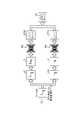
- FIG. 1 is a block diagram showing an example of a functional configuration of the server device according to the first embodiment.
- FIG. 2 is a diagram showing an example of a simple circuit and a complicated circuit.
- FIG. 3 is a diagram showing an example of a machine learning method of an EMI prediction model.
- FIG. 4 is a diagram showing an example of EMI prediction of a complex circuit.
- FIG. 5 is a diagram showing an example of EMI prediction of a circuit with elements.
- FIG. 6 is a diagram showing an example of variations in substrate characteristics.
- FIG. 7 is a diagram schematically showing the geometric shape of the circuit.
- FIG. 8 is a diagram showing an application example of simulation and data expansion.
- FIG. 9 is a diagram showing an example of data expansion.
- FIG. 10 is a diagram showing an example of crosstalk determination.
- FIG. 1 is a block diagram showing an example of a functional configuration of the server device according to the first embodiment.
- FIG. 2 is a diagram showing an example of a simple circuit and
- FIG. 11 is a diagram showing an example of a method of dividing into partial lines.
- FIG. 12 is a flowchart (1) showing a procedure of training data generation processing according to the first embodiment.
- FIG. 13 is a flowchart (2) showing the procedure of the training data generation process according to the first embodiment.
- FIG. 14 is a diagram showing an example of hardware configuration of a computer.
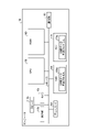
- FIG. 1 is a block diagram showing an example of the functional configuration of the server device 10 according to the first embodiment.
- the server device 10 shown in FIG. 1 is an example of a computer that provides a training data generation function for generating training data used for training a machine learning model that predicts EMI intensity in an electronic circuit.
- a machine learning model for predicting EMI intensity in an electronic circuit may be referred to as an “EMI prediction model”.
- Such a training data generation function can be packaged as a function of a machine learning service that executes machine learning of an EMI prediction model using the above training data.
- the above-mentioned training data generation function or the above-mentioned machine learning service is a model providing service that provides a trained EMI prediction model, or an EMI prediction that predicts the EMI intensity of a circuit using a trained EMI prediction model. It can be packaged as a function of the service.
- the above-mentioned model providing service or the above-mentioned EMI prediction service can be packaged as a function of a simulation service for executing a simulation of electromagnetic wave analysis.
- the server device 10 can be implemented by installing a training data generation program that realizes the above training data generation function on an arbitrary computer.
- the server device 10 can be implemented as a server that provides the above training data generation function on-premises.
- the server device 10 can be implemented as a SaaS (Software as a Service) type application to provide the above training data generation function as a cloud service.
- SaaS Software as a Service
- the server device 10 can be communicably connected to the client terminal 30 via the network NW.
- the network NW may be any kind of communication network such as the Internet or LAN (Local Area Network) regardless of whether it is wired or wireless.
- the client terminal 30 is an example of a computer that receives the above training data generation function.
- the client terminal 30 may be supported by a desktop computer such as a personal computer.
- a desktop computer such as a personal computer.
- the client terminal 30 may be any computer such as a laptop computer, a mobile terminal device, or a wearable terminal.
- FIG. 1 shows an example in which the above training data generation function is provided by the client-server system, but the present invention is not limited to this example, and the above training data generation function may be provided standalone.
- EMI prediction has one aspect that is useful for the design of electronic circuit boards, so-called circuit design. That is, in circuit design, there is a great deal of interest in keeping the radiated electromagnetic waves observed in the circuit within the specified values set for each frequency from the viewpoint of standards and regulations. For this reason, in circuit design, EMI prediction is performed by simulation of electromagnetic field analysis. However, factors such as circuit modeling costs and simulator calculation costs are hurdles for implementing simulations.
- neural networks such as machine learning technologies such as CNN (Convolutional Neural Network) are used.
- CNN Convolutional Neural Network
- an analysis target is used using a trained EMI prediction model generated from training data in which circuit information and simulation results of electromagnetic field analysis for the circuit information are associated with each other. The EMI intensity in the circuit is predicted.
- the training data from which the characteristics of the circuit that affect the EMI are extracted is the EMI prediction model.
- the condition is that it is used for training.
- advanced technology 1 and advanced technology 2 as technologies for reducing the number of training data.
- the advanced technology 1 and the advanced technology 2 mentioned here are distinguished from the prior art described in known patent documents, non-patent documents, and the like.
- the circuit is classified into “simple circuit” and "complex circuit” according to the presence or absence of branching of the line wired to the circuit. For example, a circuit without a branch is classified as a "simple circuit", while a circuit with a branch is classified as a "complex circuit”. Under such a classification, in the advanced technology 1, the point of view that a complicated circuit can be expressed by a combination of simple circuits is utilized for solving the problem of reducing the number of training data.
- FIG. 2 is a diagram showing an example of a simple circuit and a complicated circuit.
- a complex circuit C1 is shown as an example, and a simple circuit c1 and a simple circuit c2 are shown as an example of a combination of simple circuits corresponding to the complicated circuit C1.
- the complex circuit C1 can be divided into the simple circuit c11 and the simple circuit c12 with the branch point b1 as a boundary.
- the combination of each of the partial line including the excitation source ES1 and the partial line not including the excitation source ES1 among the three partial lines branching from the branch point b1 is complicated as the line of the simple circuit c11 and the simple circuit c12.
- the circuit C1 is divided.
- the complex circuit C1 can be obtained by synthesizing the simple circuit c11 and the simple circuit c12, and the complex circuit C1 can be obtained by synthesizing the EMI strength 200A of the simple circuit c11 and the EMI strength 200B of the simple circuit c12. EMI strength 20 is obtained.
- FIG. 3 is a diagram showing an example of a machine learning method of an EMI prediction model.
- the training data set DS1 is used for machine learning of the EMI prediction model M1.
- the training data set DS1 is a set of training data in which the circuit information of the simple circuits c11 to cN and the EMI intensities 400A to 400N observed in each of the simple circuits c11 to cN are associated with each other.
- the "circuit information” referred to here may include information on the network of elements included in the electronic circuit, for example, a netlist.
- the "EMI intensity” referred to here may be, as an example, a distribution of EMI intensity in a specific frequency domain, a so-called EMI spectrum.
- the EMI intensity 300A is output from the EMI prediction model m1.
- the parameters of the EMI prediction model m1 are updated based on the loss between the EMI strengths of 300B to 300N, which is the output of the EMI prediction model m1, and the EMI strengths of 400A to 400N of the correct label.
- FIG. 4 is a diagram showing an example of EMI prediction of a complicated circuit.
- FIG. 4 shows, as an example, an example of predicting the EMI intensity of the complex circuit C1 using the trained EMI prediction model M1 shown in FIG.
- the complex circuit C1 is divided into the simple circuit c11 and the simple circuit c12 with the branch point b1 as a boundary.
- the EMI prediction of the simple circuit c11 and the EMI prediction of the simple circuit c12 are performed in parallel. That is, by inputting the circuit information of the simple circuit c11 into the EMI prediction model M1, the estimated value 200A of the EMI intensity can be obtained as the output of the EMI prediction model M1.
- the estimated value 200B of the EMI intensity can be obtained as the output of the EMI prediction model M1.
- the estimated value 20 of the EMI intensity of the complex circuit C1 is obtained.
- EMI prediction of a complicated circuit can be realized by synthesizing the result of EMI prediction of a simple circuit by the EMI prediction model M1 for a simple circuit. Therefore, according to the advanced technology 1, the training data of the complicated circuit can be reduced. Further, in the advanced technology 1, the effect of reducing the number of training data increases as the domain of the EMI prediction model has more branch patterns of the circuit line.
- the circuit having an element having an LCR element such as an inductor (L), a capacitor (C), and a resistor (R) has a pattern in which the current is reflected by the element and a pattern in which the current is not reflected by the element.
- L inductor
- C capacitor
- R resistor
- One of the points of interest is the point that can be expressed by the combination of the above two points.
- the current component reflected by the element may be described as “reflection component”
- the current component not reflected by the element may be described as “non-reflection component”. ..
- the circuit with elements is divided into a circuit equivalent to reflection and a circuit equivalent to non-reflection.
- the "circuit equivalent to reflection” here is an element under the condition that the ratio of the reflection component and the non-reflection component is 1: 0, in other words, the non-reflection component is not observed and only the reflection component is observed. It refers to a circuit whose wiring is the line of the part where the current is observed in the wiring of the circuit.
- the “circuit equivalent to non-reflection” is an element under the condition that the ratio of the reflection component and the non-reflection component is 0: 1, that is, the condition that the reflection component is not observed and only the non-reflection component is observed. Yes Refers to a circuit in which the wiring of the circuit where the current is observed is the wiring.
- the explanatory variable of the EMI prediction model m2 can be a current distribution calculated from the circuit information of the circuit corresponding to reflection or the circuit information of the circuit corresponding to non-reflection.
- the "circuit information" referred to here may include information on the circuit network of the elements included in the electronic circuit, for example, a netlist, as well as physical property values of each element, such as resistance value, inductance, and capacitance.
- all the current distributions calculated for each frequency component included in the frequency domain can be used for machine learning of the EMI prediction model m2, but the details will be described later, but the resonance frequency is represented as the current distribution representing the frequency domain.
- a current distribution can be used.
- the parameters of the EMI prediction model m2 are updated based on. This gives the EMI prediction model M2 in which only the reflection-equivalent circuit and the non-reflection-equivalent circuit are trained.
- the following reference is made as the reference data referred to at the time of EMI prediction of the circuit with elements. Data is generated.
- a look-up table or a function in which the correspondence between the physical property value of the element arranged in the circuit with the element and the ratio of the reflective component and the non-reflective component can be used can be used.
- reflection occurs in a region where the value of the inductor (L) is extremely large, a region where the value of the capacitor (C) is extremely small, and a region where the value of the resistor (R) is extremely large.
- the reflection becomes sufficiently small.
- the physical characteristic value of the element in which the ratio of the reflective component and the non-reflective component is 1: 0 and the physical characteristic value of the element in which the ratio of the reflective component and the non-reflective component is 0: 1 are searched for.
- the capacitance of the capacitor (C) is 1 nF, no reflective component is observed, and only a non-reflective component is observed.
- the capacitance "1nF" of the capacitor (C) is associated with the reflective component "0" and the non-reflective component "1".
- the capacitance of the capacitor (C) is 1 pF
- the reflective component and the non-reflective component are observed at the same ratio.
- the capacitance "1pF” of the capacitor (C) is associated with the reflective component "0.5” and the non-reflective component "0.5".
- the capacitance of the capacitor (C) is 100 fF
- the non-reflective component is not observed and only the reflected component is observed.
- the capacitance "1fF” of the capacitor (C) is associated with the reflective component "1" and the non-reflective component "0".
- the ratio of the reflective component and the non-reflective component corresponding to 1 pF in the capacitance range of the capacitor (C) from 100 fF to 1 nF is given as an example, but any number of corresponding relationships can be used. May be defined.
- FIG. 5 is a diagram showing an example of EMI prediction of a circuit with elements.
- FIG. 5 shows, as an example, an example of predicting the EMI intensity of the circuit C2 with elements using the trained EMI prediction model M2.
- the component ratio "0.5: 0.5" is referenced from the reference data.
- the circuit C2 with an element is divided into a circuit c21 corresponding to reflection and a circuit c22 corresponding to non-reflection.
- the EMI prediction of the circuit c21 corresponding to the reflection and the EMI prediction of the circuit c22 corresponding to the non-reflection are performed in parallel. That is, the current distribution I1 of the circuit c21 corresponding to the reflection is calculated by inputting the circuit information of the circuit c21 corresponding to the reflection into the circuit simulator. By inputting the current distribution I1 of the circuit c21 corresponding to the reflection calculated in this way to the EMI prediction model M2, the estimated value 210A of the EMI intensity can be obtained as the output of the EMI prediction model M2. Further, the current distribution I2 of the circuit c22 corresponding to non-reflection is calculated by inputting the circuit information of the circuit c22 corresponding to non-reflection into the circuit simulator.
- the estimated value 210B of the EMI intensity can be obtained as the output of the EMI prediction model M2.
- the estimated EMI intensity 210A and the estimated EMI intensity 210B are combined according to the ratio of the reflective component and the non-reflective component referred to from the reference data "0.5: 0.5", whereby the circuit C2 with an element is used.
- the estimated value 21 of the EMI intensity of is obtained.
- the EMI prediction of the circuit with elements can be realized by synthesizing the EMI prediction results of the circuit equivalent to reflection and the circuit equivalent to non-reflection. Therefore, according to the advanced technology 2, it is possible to reduce the training data of the circuit other than the circuit corresponding to the reflection and the circuit corresponding to the non-reflection per the circuit with one element. Further, the advanced technology 2 has a higher effect of reducing the number of training data in the domain of the EMI prediction model having more patterns of elements arranged in the circuit and their physical property values.
- the division and composition exemplified in the advanced technology 1 and the advanced technology 2 only support a single-line branch circuit or a circuit with elements, and are therefore difficult to apply to a multi-line circuit.
- crosstalk refers to an electromagnetic coupling caused by either a capacitive coupling or an inductive coupling.
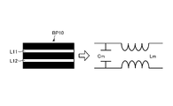
- FIG. 6 is a diagram showing an example of crosstalk occurrence.
- FIG. 6 shows a top view of the substrate BP10.
- the substrate BP10 includes two lines L11 and a line L12. These lines L11 and L12 are not connected as wiring of a circuit.
- a virtual capacitor called mutual capacitance Cm is formed.
- inductive coupling occurs, a virtual coil called mutual inductance Lm is formed.
- the mutual capacitance Cm and the mutual inductance Lm are electromagnetically coupled. In this case, the characteristic impedances of the line L11 and the line L12 change.
- the EMI also changes. Therefore, since the line L11 and the line L12 where crosstalk occurs are not equivalent to the synthesis of a single line, the division and synthesis exemplified in the advanced technology 1 and the advanced technology 2 cannot be applied.
- the prediction accuracy may decrease. For example, if only one of the circuits of a plurality of lines is supported, the current generated in the other lines is ignored, so that the accuracy of EMI prediction is lowered. From this, when trying to include a circuit of a plurality of lines in the domain to which the task of the above EMI prediction model is applied, the variation of the circuit to be predicted increases.
- a training data set containing a wide range of potential prediction targets is created, and the training of the machine learning model is executed using the training data set.
- the variation of the circuit to be predicted increases.
- 1000 training data are basically sampled as an example.
- the training data of 1000 cases of each line is sampled, if the combination of 1 line to 3 lines is included, 10 Estimated 3.003 million cases will be required.
- the modeling cost of the circuit information input to the circuit simulator and the calculation cost of the circuit simulator also increase.
- the training data generation function either generates the current distribution of the two lines by simulation according to the ratio of the distance between the two lines and the distance between the two lines and the GND layer, or generates the current distribution of each line. Training data is generated by switching whether to synthesize the current distribution.
- FIG. 7 is a diagram schematically showing the geometric shape of the circuit.
- FIG. 7 shows a side view of the substrate BP20 in which two lines L21 and lines L22 are arranged in parallel on the GND layer.
- the values of mutual capacitance (Cm) and mutual inductance (Lm) formed between the line L21 and the line L22 when crosstalk occurs are the distance s between the line L21 and the line L22 and the GND layer from the line L21 and the line L22. It is determined by the distance h to.
- the formula for calculating the mutual inductance (Lm) is as shown in the following formula (1). “ ⁇ ” in the following equation (1) indicates a magnetic constant.
- the formula for calculating the mutual capacitance (Cm) is as shown in the following formula (2). “ ⁇ ” in the following equation (2) refers to the permittivity. Further, “F” in the following formula (2) is expressed by the following formula (3). Further, “Fm” in the following formula (1) and the following formula (2) is expressed by the following formula (4).
- one of the points of focus in this embodiment is that the tracks where crosstalk does not occur can be regarded as the sum of the tracks. Only with such a point of view is a data extension that synthesizes the current distribution that has been calculated individually from each line before the simulation, instead of the simulation that calculates the current distribution of two lines that are not connected by crosstalk. Motivation to do.
- FIG. 8 is a diagram showing an application example of simulation and data expansion.
- FIG. 8 shows an example in which training data is generated from variations in the shape of each of the 1st to 3rd lines as an example. Further, FIG. 8 shows excerpts of circuits C11 to C13 as variations of the shape of one line. Further, FIG. 8 shows excerpts of the circuit C21 and the circuit C22 as variations of the shape of the two lines, and excerpts of the circuits C31 and C32 as variations of the shape of the three lines. Note that FIG. 8 shows a combination of lines that are not connected to each other via crosstalk among circuits of a plurality of lines by hatching.
- the circuit C11 is a single-line circuit
- a simulation for calculating the current distribution of the circuit C11 is performed by inputting the circuit information of the circuit C11 into the circuit simulator. Then, training data is generated from the current distribution of the circuit C11 calculated by the simulation.
- the circuit C12 is also a single-line circuit like the circuit C11
- training data is generated from the current distribution of the circuit C12 calculated by the simulation in the same manner as the circuit C11.
- the circuit C13 is also a single-line circuit like the circuit C11, training data is generated from the current distribution of the circuit C13 calculated by the simulation in the same manner as the circuit C11.
- circuit C21 crosstalk occurs between the two lines.
- a simulation for calculating the current distribution of the circuit C21 is performed by inputting the circuit information of the circuit C21 to the circuit simulator. Then, training data is generated from the current distribution of the circuit C21 calculated by the simulation.
- the circuit C22 since crosstalk does not occur between the two lines L221 and the line L222, there is room for data expansion.
- the circuit C22 can be regarded as the sum of the lines of the circuit C12 and the lines of the circuit C13. Therefore, training data is generated from the current distribution of the circuit C22 obtained by data expansion obtained by adding the calculated current distribution of the circuit C12 and the calculated circuit C13.
- the circuit C31 there is a line L311 and a line L312 that are not connected to each other via crosstalk, so there is room for data expansion.
- the circuit C31 can be regarded as the sum of the lines of the circuit C21 and the lines of the circuit C14 (not shown). Therefore, training data is generated from the current distribution of the circuit C31 obtained by data expansion obtained by adding the calculated current distribution of the circuit C21 and the calculated current distribution of the circuit C14.
- the circuit C32 since the three lines are connected to each other via crosstalk, there is no room for data expansion. In this case, a simulation for calculating the current distribution of the circuit C32 is performed by inputting the circuit information of the circuit C32 into the circuit simulator. Then, training data is generated from the current distribution of the circuit C32 calculated by the simulation.
- FIG. 9 is a diagram showing an example of data expansion.
- FIG. 9 illustrates, as an example, a data extension for generating training data from the circuit C22 shown in FIG. As shown in FIG. 9, the circuit C22 is divided into the circuit C221 and the circuit C222 with a portion where there is no crosstalk as a boundary.
- a circuit having a geometric shape similar to the geometric shape of the circuit C221 is searched from the circuit whose current distribution has been calculated by simulation. Since the circuit C12 is hit by such a search, the calculated current distribution I12 and EMI intensity P12 of the circuit C12 can be obtained.
- a circuit having a geometric shape similar to the geometric shape of the circuit C222 is searched from the circuit whose current distribution has been calculated by simulation. Since the circuit C13 is hit by such a search, the calculated current distribution I13 and EMI intensity P13 of the circuit C13 can be obtained.
- the current distribution I22 of the circuit C22 is generated by synthesizing the current distribution I12 of the circuit C12 and the current distribution I13 of the circuit C13.
- the EMI intensity P22 of the circuit C22 is generated by synthesizing the EMI intensity P12 of the circuit C12 and the EMI intensity P13 of the circuit C13.
- the training data generation function As described above, does the training data generation function according to this embodiment generate the current distribution of the two lines by simulation according to the ratio between the distance between the two lines and the distance between the two lines and the GND layer? , The training data is generated by switching whether to synthesize the current distribution of each line. For example, in the example shown in FIG. 8, two training data of the circuit C22 and the circuit C31 out of the seven circuits can be generated through data expansion. Therefore, it is possible to reduce the modeling cost of the circuit C22 and the circuit C31 input to the circuit simulator, and the cost of calculating the current distribution and the EMI intensity of the circuit C22 and the circuit C31 by the circuit simulator. Therefore, according to the training data generation function according to the present embodiment, it is possible to reduce the amount of calculation at the time of training data generation. For example, it is possible to reduce the number of simulation executions when generating training data for a circuit of a plurality of lines.
- FIG. 1 schematically shows a block corresponding to a function of the server device 10.
- the server device 10 has a communication interface unit 11, a storage unit 13, and a control unit 15.
- FIG. 1 only shows an excerpt of the functional part related to the above data generation function, and the functional part other than the figure, for example, the functional part that the existing computer is equipped with by default or as an option is a server. It may be provided in the device 10.
- the communication interface unit 11 corresponds to an example of a communication control unit that controls communication with another device, for example, a client terminal 30.
- the communication interface unit 11 can be realized by a network interface card such as a LAN card.
- the communication interface unit 11 receives a request for training data generation and various user settings related to the training data generation function from the client terminal 30. Further, the communication interface unit 11 outputs a set of training data generated by the training data generation function, a trained EMI prediction model, and the like to the client terminal 30.
- the storage unit 13 is a functional unit that stores various types of data.
- the storage unit 13 is realized by storage, for example, internal, external or auxiliary storage.
- the storage unit 13 stores the circuit information group 13A, the training data set 13B, and the model data 13M.
- the storage unit 13 can store various data such as account information of the user who receives the training data generation function.
- the explanation of the training data set 13B and the model data 13M will be described later together with the explanation of the generation unit 18 or the training unit 19.
- the circuit information group 13A is a set of n circuit information. For example, when an EMI prediction model of a circuit having a maximum of k lines is generated, n pieces are followed by procedures such as 1-line shape variation, 2-line shape variation, ..., K-line shape variation. The circuits of training data candidates are listed. The n circuit information corresponding to each of the n training data candidate circuits enumerated in this way is stored in the storage unit 13.
- the circuit information may include circuit geometry information, circuit connection information, and the like.
- the geometric shape information may include geometric shapes such as shapes and arrangements of lines, GND layers, and the like.
- the geometric shape may include coordinates such as a start point, an end point, a bending point, a relay point, and a branch point forming a line, as well as coordinates such as a vertex, a center of gravity point, and a center point forming a surface of the GND layer.
- coordinates may be two-dimensional coordinates corresponding to the surface of the substrate, but may be three-dimensional coordinates including axes in the layer direction, for example, in the vertical direction.
- the connection information includes a netlist used in a circuit simulator such as SPICE (Simulation Program with Integrated Circuit Emphasis).
- SPICE Simulation Program with Integrated Circuit Emphasis
- connection information can be acquired by importing from a design support program such as a CAD (Computer-Aided Design) system.
- the control unit 15 is a processing unit that controls the entire server device 10.
- the control unit 15 is realized by a hardware processor.
- the control unit 15 includes an acquisition unit 16, a determination unit 17, a generation unit 18, and a training unit 19.
- the acquisition unit 16 is a processing unit that acquires circuit information.
- the acquisition unit 16 can start the process when the request for training data generation is received from the client terminal 30.
- the acquisition unit 16 can also perform initial setting of various parameters related to the training data generation function as an example. For example, a crosstalk determination criterion to be compared with the ratio of the distance s between the two lines to the distance h from the line to the GND layer, for example, the threshold value d is set.
- the user setting received via the client terminal 30 may be applied to the threshold value d, or the system setting determined by the designer or the like of the training data generation function may be applied.
- the acquisition unit 16 acquires the circuit information of the circuits of n training data candidates by referring to the circuit information group 13A stored in the storage unit 13.
- the determination unit 17 is a processing unit that determines whether or not the relationship between the distance between the two lines included in the circuit information and the distance between the two lines and the GND layer satisfies the condition. As an example, the determination unit 17 pairs two independent lines among the lines included in the circuit of the training data candidate for each circuit of the training data candidate acquired by the acquisition unit 16. For example, assuming that the circuit of the training data candidate includes m lines, two n C pairs corresponding to the combination obtained by extracting two lines from the m lines are obtained. Then, the determination unit 17 calculates the shortest distance s of the two lines corresponding to the pair for each pair of nC . Then, the determination unit 17 determines whether or not the shortest distance s of the two lines is equal to or greater than the threshold value d, which is an example of the crosstalk determination criterion.
- 5 * h can be set as the threshold value d of the crosstalk determination criterion.
- the threshold value d of the crosstalk determination criterion can be determined to be 5 * h. In this case, if the shortest distance s is 5 * h or more, it is determined that crosstalk does not occur, while if it is not 5 * h or more, it is determined that crosstalk occurs.
- the threshold value d of the crosstalk determination criterion may be an arbitrary value set by the user regardless of the system setting.
- FIG. 10 is a diagram showing an example of crosstalk determination.
- FIG. 10 shows, as an example, an example of determining the crosstalk of the circuit C31.
- the circuit C31 includes three lines L311, a line L312 and a line L313.
- the presence or absence of crosstalk is determined for each pair of 3C 2 corresponding to the combination obtained by extracting two lines from the three lines L311, L312 and L313.
- the pair of the line L311 and the line L313 is extracted as the circuit C311
- the pair of the line L311 and the line L312 is extracted as the circuit C312, and the pair of the line L312 and the line L313 is used.
- circuit C313 An excerpt is shown as circuit C313. As shown in circuit C311 the pair of line L311 and line L313 is determined to have crosstalk. On the other hand, as shown in the circuit C312 and the circuit C313, the pair of the line L311 and the line L312 is determined to have no crosstalk, and the pair of the line L312 and the line L313 is also determined to have no crosstalk.
- the determination unit 17 determines whether or not there are lines that cannot reach each other via crosstalk in the circuit of the training data candidate being selected. Then, when there are lines that cannot be reached from each other via crosstalk, it is found that the circuit of the training data candidate has room for applying data extension. In this case, the selected training data candidate circuit is added to the list of data expansion candidates among the list of data expansion candidates and the list of simulation candidates stored in a storage area such as a memory or storage (not shown). On the other hand, if there are no lines that are inaccessible to each other via crosstalk, it turns out that there is no room for data extension in the training data candidate circuit. In this case, the selected training data candidate circuit is added to the list of simulation candidates.
- the line L311 and the line L313 are connected via crosstalk.
- crosstalk does not occur between the pair of the line L311 and the line L312 and the pair of the line L312 and the line L313. Therefore, it is impossible to reach the line L312 via either the line L311 or the line L313. Therefore, the line L311 and the line L313 and the line L312 are identified as unreachable.
- the determination unit 17 has a circuit having a geometric shape that matches the geometric shape of the partial line for each partial line that cannot be reached via crosstalk in the list of simulation candidates. Further determine whether or not.
- the determination unit 17 divides the circuit of the training data candidate into a partial line for each circuit of the training data candidate included in the list of data expansion candidates.
- FIG. 11 is a diagram showing an example of a method of dividing into partial lines.
- FIG. 11 shows an example in which the circuit C31 shown in FIG. 10 is divided into partial lines.
- the pair determined to have crosstalk is the line L311 and the line L313, and the other pair is determined to have no crosstalk.
- the virtual line V1 is set for the pair of the line L311 and the line L313 determined to have crosstalk.
- the virtual line V1 is set at a position connecting the shortest distance s of the line L311 and the line L313.
- the circuit C31 is divided into a place where there is no connection, for example, a pair determined to have no crosstalk as a boundary.
- it is divided into a partial line C311 including the line L311 and the line L313, and a C312 including the line L312. Then, the virtual line V1 set before the division is deleted.
- the division into partial lines is realized by searching for lines that are inaccessible to each other via crosstalk.
- crosstalk occurs between line A and line B, crosstalk does not occur between line A and line C, and , It is assumed that cross talk does not occur between the line B and the line C.
- the connection relationship including the electromagnetic connection is (AB, C). Therefore, the circuit is divided into a partial line AB and a partial line C.
- crosstalk occurs between line A and line B, and crosstalk also occurs between line B and line C. Further, it is assumed that cross talk does not occur between the line A and the line C.
- the connection relationship including the electromagnetic connection is (ABC)
- the circuit cannot be divided into partial lines.
- the determination unit 17 searches the list of simulation candidates for a circuit having a geometric shape that matches the geometric shape of the partial line for each partial line.
- Such geometrical matching is a feature point that forms a line between the line and the partial line of the training data candidate circuit stored in the list of simulation candidates, such as start and end points, bend points, relay points, and branches. This can be achieved by matching coordinates such as points.
- the matching of geometric shapes is taken as an example here, it is not always necessary to make an exact match, provided that the similarity is equal to or higher than the threshold value, or the distance or dissimilarity is within the threshold value. You can also perform matching.
- the determination unit 17 shifts the circuit of the training data candidate that is the division source from the list of data expansion candidates to the list of simulation candidates. That is, the circuit entry of the training data candidate is deleted from the list of data extension candidates, and the entry is added to the list of simulation candidates.
- the circuit of the training data candidate that is the division source is insufficient for synthesis during data expansion. Turns out not. In this case, the transition from the list of data extension candidates to the list of simulation candidates is not performed.
- the generation unit 18 is a processing unit that generates training data corresponding to the circuit of the training data candidate. As shown in FIG. 1, the generation unit 18 has a simulation unit 18A and a data expansion unit 18B.
- the simulation unit 18A is a processing unit that generates training data by simulation.
- the simulation unit 18A executes the following processing for each training data candidate circuit stored in the simulation candidate list. That is, the simulation unit 18A executes a simulation for calculating the current distribution and the EMI intensity of the circuit by inputting the circuit information of the training data candidate circuit into the circuit simulator.
- the circuit simulator is executed on the server device 10, but the circuit simulator may be executed by an arbitrary execution subject. For example, an API (Application Programming Interface) published by an external device, service, or software that executes a circuit simulator can be used to request calculation of current distribution and EMI intensity. After that, the simulation unit 18A generates training data associated with the current distribution and the EMI intensity obtained by the simulation.
- API Application Programming Interface
- the circuit simulator calculates the current distribution for each frequency component included in a specific frequency domain based on the input circuit information.
- a current distribution image of the circuit calculated by the circuit simulator for example, a current distribution image in which the intensity of the current flowing on the substrate surface is mapped on a two-dimensional map can be obtained for each frequency component.
- the simulation unit 18A identifies one or a plurality of resonance frequencies at which the maximum value of the current distribution calculated for each frequency component has a maximum.
- the simulation unit 18A processes the pixel values of the pixels included in the current distribution image corresponding to the resonance frequency based on the distance from the line of each pixel from the aspect of approximating the near field of the electronic circuit. To execute. For example, as the current flowing on the line increases, the shading value approaches the upper limit value, for example, 255 corresponding to white, while as the current decreases, the shading value approaches the lower limit value, for example, 0 corresponding to black.
- the current distribution image generated by this is taken as an example. In this case, as the distance from the line of the pixel included in the current distribution image becomes smaller, the shift amount for shifting the shading value of the pixel to the upper limit value side is set larger.
- the shift amount for shifting the shading value of the pixel to the lower limit value side is set smaller.
- the simulation unit 18A generates training data in which the resonance frequency and current distribution image and the EMI intensity are associated with each other.
- the resonance frequency which is a scalar value
- the resonance frequency is converted into a matrix that can be input to a standard neural network as an example of the EMI prediction model.
- a matrix corresponding to the two-dimensional array of the current distribution image is generated from the aspect of unifying the matrix of each channel to the same type.
- the value of the resonance frequency is embedded in each element of the matrix. Training data in which the matrix and the current distribution image (matrix) in which the resonance frequency generated in this way is embedded and the EMI intensity which is the correct label are associated with each other is generated.
- the data expansion unit 18B is a processing unit that generates training data by data expansion.
- the data expansion unit 18B executes the following processing for each training data candidate circuit stored in the data expansion list in the order in which the data expansion is registered in the list. That is, the data expansion unit 18B divides the training data candidate circuit into partial lines. Then, the data expansion unit 18B selects a circuit having a geometric shape similar to the geometric shape of the partial line from the circuits in which the training data is generated by the simulation unit 18A for each partial line obtained by the division. search for. After that, the data expansion unit 18B acquires the calculation results of the current distribution and the EMI intensity for each partial line as the simulation results corresponding to the circuits hit by the search.
- the data expansion unit 18B generates the current distribution of the circuit of the training data candidate by synthesizing the current distribution acquired for each sub-line between each sub-line. Further, the data expansion unit 18B generates the EMI intensity of the circuit of the training data candidate by synthesizing the EMI intensity acquired for each partial line between the partial lines. Then, the data expansion unit 18B generates training data for the circuit of the training data candidate by associating the current distribution after synthesis with the EMI intensity of the synthetic word.
- the generation unit 18 registers the set of the training data generated for each circuit information in the storage unit 13 as the training data set 13B. do.
- the training unit 19 is a processing unit that trains an EMI prediction model using training data for machine learning.
- the training unit 19 may use the training unit 19. Perform the following processing. That is, the training unit 19 trains the EMI prediction model with the current distribution of the training data included in the training data set 13B as the feature quantity and the EMI intensity as the objective variable.
- the training unit 19 inputs the resonance frequency corresponding to the input data of channel 1 and the current distribution image corresponding to the input data of channel 2 into the EMI prediction model. As a result, an estimated value of EMI intensity is obtained as the output of the EMI prediction model.
- the training unit 19 updates the parameters of the EMI prediction model based on the loss between the estimated value of the EMI intensity output by the EMI prediction model and the EMI intensity of the correct label. This gives a trained EMI prediction model.
- model data 13M The data related to the trained EMI prediction model obtained in this way is stored in the storage unit 13 as model data 13M.
- the model data 13M includes the layer structure of the machine learning model such as neurons and synapses of each layer of the input layer, the hidden layer, and the output layer, and the weights and biases of each layer.
- Machine learning model parameters may be included.
- model providing service may be performed by providing the model data of the trained EMI prediction model to the client terminal 30, or the EMI prediction for predicting the EMI intensity of the circuit using the trained EMI prediction model. Services may be provided.
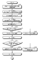
- 12 and 13 are flowcharts showing the procedure of the training data generation process according to the first embodiment. As one aspect, this process can be started when a request for training data generation is received from the client terminal 30.
- the acquisition unit 16 acquires circuit information of n training data candidate circuits by referring to the circuit information group 13A stored in the storage unit 13 (step S101).
- the determination unit 17 starts the loop process 1 that repeats the processes from step S102 to step S109 for the number of times corresponding to the number of circuits of n training data candidates acquired in step S101.
- the processing from step S102 to step S106 may be executed in parallel.
- the determination unit 17 pairs two independent lines among the lines included in the circuit of the training data candidate during the loop processing (step S102). For example, assuming that the circuit of the training data candidate includes m lines, two n C pairs corresponding to the combination obtained by extracting two lines from the m lines are obtained.
- the determination unit 17 starts the loop process 2 that repeats the processes from step S103 to step S106 for the number of times corresponding to the pair of two nCs obtained by the pairing in step S102.
- the processing from step S103 to step S106 may be executed in parallel.
- the determination unit 17 calculates the shortest distance s of the two lines corresponding to the pair during the loop processing (step S103). Then, the determination unit 17 determines whether or not the shortest distance s between the two lines is equal to or greater than the crosstalk determination criterion d (step S104).
- step S104Yes when the shortest distance s is equal to or greater than the crosstalk determination criterion d (step S104Yes), it is identified that crosstalk does not occur (step S105).
- step S104No when the shortest distance s is not equal to or greater than the crosstalk determination criterion d (step S104No), it is identified that crosstalk occurs (step S106).
- the determination unit 17 determines whether or not there are lines that cannot reach each other via crosstalk in the circuit of the training data candidate during the loop processing (step S107). Then, when there are lines that cannot be reached from each other via crosstalk (step S107Yes), it is found that there is room for applying data expansion to the circuit of the training data candidate. In this case, the circuit of the training data candidate during the loop processing is added to the list of data expansion candidates (step S108).
- step S107No when there are no lines that cannot be reached from each other via crosstalk (step S107No), it is found that there is no room for applying data expansion to the circuit of the training data candidate. In this case, the circuit of the training data candidate during the loop processing is added to the list of simulation candidates (step S109).
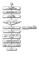
- the determination unit 17 starts the loop process 3 that repeats the processes from step S110 to step S112 shown in FIG. 13 for the number of times corresponding to the number of circuits of the training data candidates included in the list of data expansion candidates.
- the processing from step S110 to step S112 may be executed in parallel.
- the determination unit 17 divides the circuit of the training data candidate during the loop processing into partial lines (step S110). After that, the loop process 4 that repeats the processes of steps S111 and S112 is started for the number of times corresponding to the number of partial lines obtained by the division of step S110. Although an example in which the loop processing is performed is given here, the processing of step S111 and step S112 may be executed in parallel.
- the determination unit 17 searches the list of simulation candidates for a circuit having a geometric shape that matches the geometric shape during loop processing. At this time, if there is even one partial line that does not hit the search for a circuit having a geometric shape that matches the geometric shape of the partial line (step S111No), the training data candidate circuit that is the division source is combined during data expansion. It turns out that there is a shortage of circuits to use. In this case, the determination unit 17 shifts the circuit of the training data candidate that is the division source from the list of data expansion candidates to the list of simulation candidates (step S112).
- step S111No when there is no partial line that does not hit the search for a circuit having a geometric shape that matches the geometric shape of the partial line (step S111No), the circuit of the training data candidate that is the division source is used for synthesis at the time of data expansion. It turns out that there is no shortage. In this case, the transition from the list of data extension candidates to the list of simulation candidates is not performed.
- step S111 When the loop process 4 of step S111 is completed, it is identified whether or not it is necessary to shift from the list of data expansion candidates of the circuit of the training data candidate to be the division source to the list of simulation candidates. Then, when the loop process 3 from step S110 to step S112 is completed, the confirmation of migration regarding the circuits of all the training data candidates included in the list of data expansion candidates is completed.
- the simulation unit 18A generates training data of the circuit of the training data candidate stored in the list of simulation candidates by simulation (step S113).
- the data expansion unit 18B generates training data of the circuit of the training data candidate stored in the list of data expansion candidates by data expansion (step S114).
- the training unit 19 trains the EMI prediction model (step S115) with the current distribution of the training data generated in step S113 or step S114 as the feature quantity and the EMI intensity as the objective variable, and ends the process. ..
- the training data generation function generates a current distribution of two lines by simulation according to the ratio of the distance between the two lines and the distance between the two lines and the GND layer.
- Training data is generated by switching between synthesizing the current distribution of each line.
- the patterns in which training data can be generated by simulation are as follows. That is, the lines A only, the line B only, the line C only, the lines A and B (coupling), the lines A and C (coupling), the lines B and C (coupling), and the lines A and B and C (coupling).
- the patterns to which data expansion can be applied are, at the maximum, lines A and B (uncoupled), lines A and C (uncoupled), lines B and C (uncoupled), and lines A and B and C. (Only A and B are connected), lines A and B and C (only A and C are connected), and lines A and B and C (only B and C are connected). Therefore, according to the training data generation function according to the present embodiment, it is possible to reduce the amount of calculation at the time of training data generation. For example, it is possible to reduce the number of simulation executions when generating training data for a circuit of a plurality of lines.
- each component of each of the illustrated devices does not necessarily have to be physically configured as shown in the figure. That is, the specific form of distribution / integration of each device is not limited to the one shown in the figure, and all or part of them may be functionally or physically distributed / physically distributed in any unit according to various loads and usage conditions. Can be integrated and configured.
- the acquisition unit 16, the determination unit 17, the generation unit 18, or the training unit 19 may be connected via a network as an external device of the server device 10. Further, even if another device has the acquisition unit 16, the determination unit 17, the generation unit 18, or the training unit 19, and is connected to a network and cooperates with each other, the function of the server device 10 may be realized. good.
- FIG. 14 is a diagram showing an example of computer hardware configuration.
- the computer 100 has an operation unit 110a, a speaker 110b, a camera 110c, a display 120, and a communication unit 130. Further, the computer 100 has a CPU 150, a ROM 160, an HDD 170, and a RAM 180. Each of these 110 to 180 parts is connected via the bus 140.
- a CPU is taken as an example of a hardware processor, but the present invention is not limited to this. That is, it is not limited to a general-purpose processor such as a CPU or MPU, but may be a DLU (Deep Learning Unit), a GPGPU (General-Purpose computing on Graphics Processing Units), a GPU cluster, or the like.
- a general-purpose processor such as a CPU or MPU, but may be a DLU (Deep Learning Unit), a GPGPU (General-Purpose computing on Graphics Processing Units), a GPU cluster, or the like.
- the HDD 170 stores a training data generation program 170a that has the same functions as the acquisition unit 16, the determination unit 17, the generation unit 18, and the training unit 19 shown in the first embodiment. ..
- the training data generation program 170a may be integrated or separated as in the components of the acquisition unit 16, the determination unit 17, the generation unit 18, and the training unit 19 shown in FIG. That is, not all the data shown in FIG. 1 may be stored in the HDD 170, and the data used for processing may be stored in the HDD 170.
- the CPU 150 reads the training data generation program 170a from the HDD 170 and then deploys it to the RAM 180.
- the training data generation program 170a functions as the training data generation process 180a as shown in FIG.
- the training data generation process 180a expands various data read from the HDD 170 into the area allocated to the training data generation process 180a in the storage area of the RAM 180, and executes various processes using the expanded various data. ..
- the process shown in FIGS. 12 and 13 is included.
- the CPU 150 not all the processing units shown in the first embodiment need to operate, and it is sufficient that the processing units corresponding to the processes to be executed are virtually realized.
- the above training data generation program 170a does not necessarily have to be stored in the HDD 170 or ROM 160 from the beginning.
- each program is stored in a "portable physical medium" such as a flexible disk inserted into the computer 100, a so-called FD, a CD-ROM, a DVD disk, a magneto-optical disk, or an IC card. Then, the computer 100 may acquire and execute each program from these portable physical media. Further, each program is stored in another computer or server device connected to the computer 100 via a public line, the Internet, a LAN, a WAN, or the like, and the computer 100 acquires and executes each program from these. You may do it.
Landscapes
- Engineering & Computer Science (AREA)
- Theoretical Computer Science (AREA)
- Physics & Mathematics (AREA)
- Computer Hardware Design (AREA)
- Evolutionary Computation (AREA)
- Software Systems (AREA)
- General Engineering & Computer Science (AREA)
- General Physics & Mathematics (AREA)
- Computer Vision & Pattern Recognition (AREA)
- Medical Informatics (AREA)
- Artificial Intelligence (AREA)
- Geometry (AREA)
- Computing Systems (AREA)
- Mathematical Physics (AREA)
- Data Mining & Analysis (AREA)
- Microelectronics & Electronic Packaging (AREA)
- Design And Manufacture Of Integrated Circuits (AREA)
- Management, Administration, Business Operations System, And Electronic Commerce (AREA)
Priority Applications (4)
| Application Number | Priority Date | Filing Date | Title |
|---|---|---|---|
| EP20956698.3A EP4227848A4 (en) | 2020-10-06 | 2020-10-06 | TRAINING DATA GENERATION PROGRAM, TRAINING DATA GENERATION METHOD AND TRAINING DATA GENERATION APPARATUS |
| PCT/JP2020/037924 WO2022074750A1 (ja) | 2020-10-06 | 2020-10-06 | 訓練データ生成プログラム、訓練データ生成方法及び訓練データ生成装置 |
| JP2022555016A JP7416279B2 (ja) | 2020-10-06 | 2020-10-06 | 訓練データ生成プログラム、訓練データ生成方法及び訓練データ生成装置 |
| US18/193,724 US20230252356A1 (en) | 2020-10-06 | 2023-03-31 | Non-transitory computer-readable recording medium storing training data generation program, training data generation method, and training data generation device |
Applications Claiming Priority (1)
| Application Number | Priority Date | Filing Date | Title |
|---|---|---|---|
| PCT/JP2020/037924 WO2022074750A1 (ja) | 2020-10-06 | 2020-10-06 | 訓練データ生成プログラム、訓練データ生成方法及び訓練データ生成装置 |
Related Child Applications (1)
| Application Number | Title | Priority Date | Filing Date |
|---|---|---|---|
| US18/193,724 Continuation US20230252356A1 (en) | 2020-10-06 | 2023-03-31 | Non-transitory computer-readable recording medium storing training data generation program, training data generation method, and training data generation device |
Publications (1)
| Publication Number | Publication Date |
|---|---|
| WO2022074750A1 true WO2022074750A1 (ja) | 2022-04-14 |
Family
ID=81125746
Family Applications (1)
| Application Number | Title | Priority Date | Filing Date |
|---|---|---|---|
| PCT/JP2020/037924 Ceased WO2022074750A1 (ja) | 2020-10-06 | 2020-10-06 | 訓練データ生成プログラム、訓練データ生成方法及び訓練データ生成装置 |
Country Status (4)
| Country | Link |
|---|---|
| US (1) | US20230252356A1 (https=) |
| EP (1) | EP4227848A4 (https=) |
| JP (1) | JP7416279B2 (https=) |
| WO (1) | WO2022074750A1 (https=) |
Cited By (1)
| Publication number | Priority date | Publication date | Assignee | Title |
|---|---|---|---|---|
| WO2025134410A1 (ja) * | 2023-12-19 | 2025-06-26 | 株式会社デンソー | 分析装置、分析プログラム、方法、半導体装置及び半導体ウエハ |
Families Citing this family (1)
| Publication number | Priority date | Publication date | Assignee | Title |
|---|---|---|---|---|
| DE102021206323A1 (de) * | 2021-06-21 | 2022-12-22 | Robert Bosch Gesellschaft mit beschränkter Haftung | Verfahren zur Analyse einer elektrischen Schaltung |
Citations (5)
| Publication number | Priority date | Publication date | Assignee | Title |
|---|---|---|---|---|
| JPH09115101A (ja) | 1995-10-19 | 1997-05-02 | Matsushita Electric Ind Co Ltd | クロストーク現象解析装置及びこれを用いて最適化した回転トランス |
| JP2020032190A (ja) | 2018-08-30 | 2020-03-05 | 株式会社トプコン | 多変量及び多解像度網膜画像異常検出システム |
| JP2020060877A (ja) * | 2018-10-05 | 2020-04-16 | 富士通株式会社 | 推定プログラム、推定装置および推定方法 |
| WO2020095362A1 (ja) * | 2018-11-06 | 2020-05-14 | 三菱電機株式会社 | 設計支援装置、設計支援方法および機械学習装置 |
| WO2020129617A1 (ja) | 2018-12-19 | 2020-06-25 | パナソニックIpマネジメント株式会社 | 外観検査装置及びそれを用いた溶接箇所の形状不良の有無及び種類の判定精度の向上方法、溶接システム及びそれを用いたワークの溶接方法 |
Family Cites Families (2)
| Publication number | Priority date | Publication date | Assignee | Title |
|---|---|---|---|---|
| CN103728535B (zh) * | 2013-10-28 | 2016-09-14 | 昆明理工大学 | 一种基于小波变换暂态能量谱的特高压直流输电线路故障测距方法 |
| US10706197B2 (en) * | 2018-05-24 | 2020-07-07 | Hitachi, Ltd. | Automated electromagnetic interference filter design |
-
2020
- 2020-10-06 JP JP2022555016A patent/JP7416279B2/ja active Active
- 2020-10-06 WO PCT/JP2020/037924 patent/WO2022074750A1/ja not_active Ceased
- 2020-10-06 EP EP20956698.3A patent/EP4227848A4/en active Pending
-
2023
- 2023-03-31 US US18/193,724 patent/US20230252356A1/en active Pending
Patent Citations (5)
| Publication number | Priority date | Publication date | Assignee | Title |
|---|---|---|---|---|
| JPH09115101A (ja) | 1995-10-19 | 1997-05-02 | Matsushita Electric Ind Co Ltd | クロストーク現象解析装置及びこれを用いて最適化した回転トランス |
| JP2020032190A (ja) | 2018-08-30 | 2020-03-05 | 株式会社トプコン | 多変量及び多解像度網膜画像異常検出システム |
| JP2020060877A (ja) * | 2018-10-05 | 2020-04-16 | 富士通株式会社 | 推定プログラム、推定装置および推定方法 |
| WO2020095362A1 (ja) * | 2018-11-06 | 2020-05-14 | 三菱電機株式会社 | 設計支援装置、設計支援方法および機械学習装置 |
| WO2020129617A1 (ja) | 2018-12-19 | 2020-06-25 | パナソニックIpマネジメント株式会社 | 外観検査装置及びそれを用いた溶接箇所の形状不良の有無及び種類の判定精度の向上方法、溶接システム及びそれを用いたワークの溶接方法 |
Non-Patent Citations (1)
| Title |
|---|
| See also references of EP4227848A4 |
Cited By (1)
| Publication number | Priority date | Publication date | Assignee | Title |
|---|---|---|---|---|
| WO2025134410A1 (ja) * | 2023-12-19 | 2025-06-26 | 株式会社デンソー | 分析装置、分析プログラム、方法、半導体装置及び半導体ウエハ |
Also Published As
| Publication number | Publication date |
|---|---|
| EP4227848A1 (en) | 2023-08-16 |
| JPWO2022074750A1 (https=) | 2022-04-14 |
| JP7416279B2 (ja) | 2024-01-17 |
| EP4227848A4 (en) | 2023-11-22 |
| US20230252356A1 (en) | 2023-08-10 |
Similar Documents
| Publication | Publication Date | Title |
|---|---|---|
| CN111724478B (zh) | 一种基于深度学习的点云上采样方法 | |
| US20230252356A1 (en) | Non-transitory computer-readable recording medium storing training data generation program, training data generation method, and training data generation device | |
| CN111710035A (zh) | 人脸重建方法、装置、计算机设备及存储介质 | |
| CN108257178A (zh) | 用于定位目标人体的位置的方法和装置 | |
| US11829698B2 (en) | Guided power grid augmentation system and method | |
| JP6323333B2 (ja) | 基板設計方法及び設計装置 | |
| CN119440313B (zh) | 一种电容触摸屏触控调整方法、装置及电子设备 | |
| US6941528B2 (en) | Use of a layout-optimization tool to increase the yield and reliability of VLSI designs | |
| KR102464963B1 (ko) | 데이터 기반의 물체 위치 최적화를 위한 강화학습 장치 | |
| CN112233161A (zh) | 手部图像深度确定方法、装置、电子设备及存储介质 | |
| CN109325996A (zh) | 用于生成信息的方法和装置 | |
| US10740532B1 (en) | Route driven placement of fan-out clock drivers | |
| JP6044538B2 (ja) | プリント基板設計システム、及びプリント基板設計方法 | |
| JP7416278B2 (ja) | 訓練データ生成プログラム、訓練データ生成方法及び訓練データ生成装置 | |
| JP7658152B2 (ja) | Emi算出プログラム、emi算出方法およびemi算出装置 | |
| Lenarduzzi et al. | Kernel-based adaptive approximation of functions with discontinuities | |
| CN111291611A (zh) | 一种基于贝叶斯查询扩展的行人重识别方法及装置 | |
| CN109034085B (zh) | 用于生成信息的方法和装置 | |
| Patil et al. | Crow search algorithm with discrete wavelet transform to aid Mumford Shah inpainting model | |
| CN117274615B (zh) | 人体动作预测方法及相关产品 | |
| JP7409220B2 (ja) | 推定プログラム、モデル生成プログラム、推定方法、モデル生成方法、推定装置およびモデル生成装置 | |
| CN108229748B (zh) | 用于合乘服务的匹配方法、装置及电子设备 | |
| CN119150789B (zh) | 硅中介层走线方式确定方法、装置、电子设备和存储介质 | |
| US20050050501A1 (en) | The use of a layout-optimization tool to increase the yield and reliability of vlsi designs | |
| CN120975030A (zh) | 一种实时考虑模拟集成电路版图寄生的布线方法 |
Legal Events
| Date | Code | Title | Description |
|---|---|---|---|
| 121 | Ep: the epo has been informed by wipo that ep was designated in this application |
Ref document number: 20956698 Country of ref document: EP Kind code of ref document: A1 |
|
| ENP | Entry into the national phase |
Ref document number: 2022555016 Country of ref document: JP Kind code of ref document: A |
|
| NENP | Non-entry into the national phase |
Ref country code: DE |
|
| ENP | Entry into the national phase |
Ref document number: 2020956698 Country of ref document: EP Effective date: 20230508 |