WO2022074750A1 - Training data generation program, training data generation method, and training data generation device - Google Patents
Training data generation program, training data generation method, and training data generation device Download PDFInfo
- Publication number
- WO2022074750A1 WO2022074750A1 PCT/JP2020/037924 JP2020037924W WO2022074750A1 WO 2022074750 A1 WO2022074750 A1 WO 2022074750A1 JP 2020037924 W JP2020037924 W JP 2020037924W WO 2022074750 A1 WO2022074750 A1 WO 2022074750A1
- Authority
- WO
- WIPO (PCT)
- Prior art keywords
- training data
- lines
- circuit
- current distribution
- distribution information
- Prior art date
Links
- 238000012549 training Methods 0.000 title claims abstract description 228
- 238000000034 method Methods 0.000 title claims abstract description 66
- 238000009826 distribution Methods 0.000 claims abstract description 121
- 238000004088 simulation Methods 0.000 claims abstract description 72
- 230000008569 process Effects 0.000 claims abstract description 51
- 238000010801 machine learning Methods 0.000 claims abstract description 33
- 238000012545 processing Methods 0.000 claims description 39
- 230000002194 synthesizing effect Effects 0.000 claims description 13
- 230000005855 radiation Effects 0.000 claims description 8
- 230000006870 function Effects 0.000 description 29
- 238000005516 engineering process Methods 0.000 description 26
- 238000010586 diagram Methods 0.000 description 24
- 239000003990 capacitor Substances 0.000 description 12
- 230000008878 coupling Effects 0.000 description 11
- 238000010168 coupling process Methods 0.000 description 11
- 238000005859 coupling reaction Methods 0.000 description 11
- 238000004891 communication Methods 0.000 description 10
- 238000004364 calculation method Methods 0.000 description 9
- 230000015572 biosynthetic process Effects 0.000 description 7
- 238000003786 synthesis reaction Methods 0.000 description 7
- 239000011159 matrix material Substances 0.000 description 6
- 239000000758 substrate Substances 0.000 description 6
- 238000004458 analytical method Methods 0.000 description 5
- 238000013461 design Methods 0.000 description 5
- 238000013528 artificial neural network Methods 0.000 description 3
- 230000000694 effects Effects 0.000 description 3
- 230000005672 electromagnetic field Effects 0.000 description 3
- 230000001939 inductive effect Effects 0.000 description 3
- 230000000704 physical effect Effects 0.000 description 3
- 101100272680 Paracentrotus lividus BP10 gene Proteins 0.000 description 2
- 238000013459 approach Methods 0.000 description 2
- FFBHFFJDDLITSX-UHFFFAOYSA-N benzyl N-[2-hydroxy-4-(3-oxomorpholin-4-yl)phenyl]carbamate Chemical compound OC1=C(NC(=O)OCC2=CC=CC=C2)C=CC(=C1)N1CCOCC1=O FFBHFFJDDLITSX-UHFFFAOYSA-N 0.000 description 2
- 230000008859 change Effects 0.000 description 2
- 238000011960 computer-aided design Methods 0.000 description 2
- 238000013527 convolutional neural network Methods 0.000 description 2
- 230000007423 decrease Effects 0.000 description 2
- 230000005284 excitation Effects 0.000 description 2
- 230000007704 transition Effects 0.000 description 2
- 238000005452 bending Methods 0.000 description 1
- 230000033228 biological regulation Effects 0.000 description 1
- 238000012790 confirmation Methods 0.000 description 1
- 238000013135 deep learning Methods 0.000 description 1
- 230000005484 gravity Effects 0.000 description 1
- 230000012447 hatching Effects 0.000 description 1
- 230000010354 integration Effects 0.000 description 1
- 238000013508 migration Methods 0.000 description 1
- 230000005012 migration Effects 0.000 description 1
- 230000008450 motivation Effects 0.000 description 1
- 210000002569 neuron Anatomy 0.000 description 1
- 230000009467 reduction Effects 0.000 description 1
- 238000001228 spectrum Methods 0.000 description 1
- 210000000225 synapse Anatomy 0.000 description 1
Images


Classifications
-
- G—PHYSICS
- G06—COMPUTING; CALCULATING OR COUNTING
- G06F—ELECTRIC DIGITAL DATA PROCESSING
- G06F30/00—Computer-aided design [CAD]
- G06F30/30—Circuit design
- G06F30/39—Circuit design at the physical level
- G06F30/398—Design verification or optimisation, e.g. using design rule check [DRC], layout versus schematics [LVS] or finite element methods [FEM]
-
- G—PHYSICS
- G06—COMPUTING; CALCULATING OR COUNTING
- G06F—ELECTRIC DIGITAL DATA PROCESSING
- G06F30/00—Computer-aided design [CAD]
- G06F30/20—Design optimisation, verification or simulation
- G06F30/27—Design optimisation, verification or simulation using machine learning, e.g. artificial intelligence, neural networks, support vector machines [SVM] or training a model
-
- G—PHYSICS
- G06—COMPUTING; CALCULATING OR COUNTING
- G06F—ELECTRIC DIGITAL DATA PROCESSING
- G06F30/00—Computer-aided design [CAD]
- G06F30/30—Circuit design
- G06F30/36—Circuit design at the analogue level
- G06F30/367—Design verification, e.g. using simulation, simulation program with integrated circuit emphasis [SPICE], direct methods or relaxation methods
-
- G—PHYSICS
- G06—COMPUTING; CALCULATING OR COUNTING
- G06N—COMPUTING ARRANGEMENTS BASED ON SPECIFIC COMPUTATIONAL MODELS
- G06N20/00—Machine learning
Definitions
- the present invention relates to a training data generation technique.
- EMI Electromagnetic Interference
- EMI refers to the electromagnetic wave radiation state radiated from an electronic circuit.
- EMI is also referred to as a distant field from the aspect of the electromagnetic wave radiation situation, which refers to the distant electromagnetic field situation.
- the EMI intensity in the circuit to be predicted is predicted using a trained machine learning model generated from the training data in which the circuit information and the simulation result of the electromagnetic wave analysis for the circuit information are associated with each other.
- the training data generation program acquires circuit information, and whether or not the relationship between the distance between the two lines included in the circuit information and the distance between the two lines and the GND layer satisfies the condition. If the relationship satisfies the above conditions, the first current distribution information corresponding to the two lines is generated by simulation, and the training data for machine learning is generated based on the first current distribution information. When the relationship does not satisfy the above conditions, the current distribution information corresponding to each of the two lines is combined to generate the second current distribution information corresponding to the two lines, and the second current is generated. Generates training data for machine learning based on distribution information, and causes a computer to perform processing.
- FIG. 1 is a block diagram showing an example of a functional configuration of the server device according to the first embodiment.
- FIG. 2 is a diagram showing an example of a simple circuit and a complicated circuit.
- FIG. 3 is a diagram showing an example of a machine learning method of an EMI prediction model.
- FIG. 4 is a diagram showing an example of EMI prediction of a complex circuit.
- FIG. 5 is a diagram showing an example of EMI prediction of a circuit with elements.
- FIG. 6 is a diagram showing an example of variations in substrate characteristics.
- FIG. 7 is a diagram schematically showing the geometric shape of the circuit.
- FIG. 8 is a diagram showing an application example of simulation and data expansion.
- FIG. 9 is a diagram showing an example of data expansion.
- FIG. 10 is a diagram showing an example of crosstalk determination.
- FIG. 1 is a block diagram showing an example of a functional configuration of the server device according to the first embodiment.
- FIG. 2 is a diagram showing an example of a simple circuit and
- FIG. 11 is a diagram showing an example of a method of dividing into partial lines.
- FIG. 12 is a flowchart (1) showing a procedure of training data generation processing according to the first embodiment.
- FIG. 13 is a flowchart (2) showing the procedure of the training data generation process according to the first embodiment.
- FIG. 14 is a diagram showing an example of hardware configuration of a computer.
- FIG. 1 is a block diagram showing an example of the functional configuration of the server device 10 according to the first embodiment.
- the server device 10 shown in FIG. 1 is an example of a computer that provides a training data generation function for generating training data used for training a machine learning model that predicts EMI intensity in an electronic circuit.
- a machine learning model for predicting EMI intensity in an electronic circuit may be referred to as an “EMI prediction model”.
- Such a training data generation function can be packaged as a function of a machine learning service that executes machine learning of an EMI prediction model using the above training data.
- the above-mentioned training data generation function or the above-mentioned machine learning service is a model providing service that provides a trained EMI prediction model, or an EMI prediction that predicts the EMI intensity of a circuit using a trained EMI prediction model. It can be packaged as a function of the service.
- the above-mentioned model providing service or the above-mentioned EMI prediction service can be packaged as a function of a simulation service for executing a simulation of electromagnetic wave analysis.
- the server device 10 can be implemented by installing a training data generation program that realizes the above training data generation function on an arbitrary computer.
- the server device 10 can be implemented as a server that provides the above training data generation function on-premises.
- the server device 10 can be implemented as a SaaS (Software as a Service) type application to provide the above training data generation function as a cloud service.
- SaaS Software as a Service
- the server device 10 can be communicably connected to the client terminal 30 via the network NW.
- the network NW may be any kind of communication network such as the Internet or LAN (Local Area Network) regardless of whether it is wired or wireless.
- the client terminal 30 is an example of a computer that receives the above training data generation function.
- the client terminal 30 may be supported by a desktop computer such as a personal computer.
- a desktop computer such as a personal computer.
- the client terminal 30 may be any computer such as a laptop computer, a mobile terminal device, or a wearable terminal.
- FIG. 1 shows an example in which the above training data generation function is provided by the client-server system, but the present invention is not limited to this example, and the above training data generation function may be provided standalone.
- EMI prediction has one aspect that is useful for the design of electronic circuit boards, so-called circuit design. That is, in circuit design, there is a great deal of interest in keeping the radiated electromagnetic waves observed in the circuit within the specified values set for each frequency from the viewpoint of standards and regulations. For this reason, in circuit design, EMI prediction is performed by simulation of electromagnetic field analysis. However, factors such as circuit modeling costs and simulator calculation costs are hurdles for implementing simulations.
- neural networks such as machine learning technologies such as CNN (Convolutional Neural Network) are used.
- CNN Convolutional Neural Network
- an analysis target is used using a trained EMI prediction model generated from training data in which circuit information and simulation results of electromagnetic field analysis for the circuit information are associated with each other. The EMI intensity in the circuit is predicted.
- the training data from which the characteristics of the circuit that affect the EMI are extracted is the EMI prediction model.
- the condition is that it is used for training.
- advanced technology 1 and advanced technology 2 as technologies for reducing the number of training data.
- the advanced technology 1 and the advanced technology 2 mentioned here are distinguished from the prior art described in known patent documents, non-patent documents, and the like.
- the circuit is classified into “simple circuit” and "complex circuit” according to the presence or absence of branching of the line wired to the circuit. For example, a circuit without a branch is classified as a "simple circuit", while a circuit with a branch is classified as a "complex circuit”. Under such a classification, in the advanced technology 1, the point of view that a complicated circuit can be expressed by a combination of simple circuits is utilized for solving the problem of reducing the number of training data.
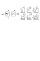
- FIG. 2 is a diagram showing an example of a simple circuit and a complicated circuit.
- a complex circuit C1 is shown as an example, and a simple circuit c1 and a simple circuit c2 are shown as an example of a combination of simple circuits corresponding to the complicated circuit C1.
- the complex circuit C1 can be divided into the simple circuit c11 and the simple circuit c12 with the branch point b1 as a boundary.
- the combination of each of the partial line including the excitation source ES1 and the partial line not including the excitation source ES1 among the three partial lines branching from the branch point b1 is complicated as the line of the simple circuit c11 and the simple circuit c12.
- the circuit C1 is divided.
- the complex circuit C1 can be obtained by synthesizing the simple circuit c11 and the simple circuit c12, and the complex circuit C1 can be obtained by synthesizing the EMI strength 200A of the simple circuit c11 and the EMI strength 200B of the simple circuit c12. EMI strength 20 is obtained.
- FIG. 3 is a diagram showing an example of a machine learning method of an EMI prediction model.
- the training data set DS1 is used for machine learning of the EMI prediction model M1.
- the training data set DS1 is a set of training data in which the circuit information of the simple circuits c11 to cN and the EMI intensities 400A to 400N observed in each of the simple circuits c11 to cN are associated with each other.
- the "circuit information” referred to here may include information on the network of elements included in the electronic circuit, for example, a netlist.
- the "EMI intensity” referred to here may be, as an example, a distribution of EMI intensity in a specific frequency domain, a so-called EMI spectrum.
- the EMI intensity 300A is output from the EMI prediction model m1.
- the parameters of the EMI prediction model m1 are updated based on the loss between the EMI strengths of 300B to 300N, which is the output of the EMI prediction model m1, and the EMI strengths of 400A to 400N of the correct label.
- FIG. 4 is a diagram showing an example of EMI prediction of a complicated circuit.
- FIG. 4 shows, as an example, an example of predicting the EMI intensity of the complex circuit C1 using the trained EMI prediction model M1 shown in FIG.
- the complex circuit C1 is divided into the simple circuit c11 and the simple circuit c12 with the branch point b1 as a boundary.
- the EMI prediction of the simple circuit c11 and the EMI prediction of the simple circuit c12 are performed in parallel. That is, by inputting the circuit information of the simple circuit c11 into the EMI prediction model M1, the estimated value 200A of the EMI intensity can be obtained as the output of the EMI prediction model M1.
- the estimated value 200B of the EMI intensity can be obtained as the output of the EMI prediction model M1.
- the estimated value 20 of the EMI intensity of the complex circuit C1 is obtained.
- EMI prediction of a complicated circuit can be realized by synthesizing the result of EMI prediction of a simple circuit by the EMI prediction model M1 for a simple circuit. Therefore, according to the advanced technology 1, the training data of the complicated circuit can be reduced. Further, in the advanced technology 1, the effect of reducing the number of training data increases as the domain of the EMI prediction model has more branch patterns of the circuit line.
- the circuit having an element having an LCR element such as an inductor (L), a capacitor (C), and a resistor (R) has a pattern in which the current is reflected by the element and a pattern in which the current is not reflected by the element.
- L inductor
- C capacitor
- R resistor
- One of the points of interest is the point that can be expressed by the combination of the above two points.
- the current component reflected by the element may be described as “reflection component”
- the current component not reflected by the element may be described as “non-reflection component”. ..
- the circuit with elements is divided into a circuit equivalent to reflection and a circuit equivalent to non-reflection.
- the "circuit equivalent to reflection” here is an element under the condition that the ratio of the reflection component and the non-reflection component is 1: 0, in other words, the non-reflection component is not observed and only the reflection component is observed. It refers to a circuit whose wiring is the line of the part where the current is observed in the wiring of the circuit.
- the “circuit equivalent to non-reflection” is an element under the condition that the ratio of the reflection component and the non-reflection component is 0: 1, that is, the condition that the reflection component is not observed and only the non-reflection component is observed. Yes Refers to a circuit in which the wiring of the circuit where the current is observed is the wiring.
- the explanatory variable of the EMI prediction model m2 can be a current distribution calculated from the circuit information of the circuit corresponding to reflection or the circuit information of the circuit corresponding to non-reflection.
- the "circuit information" referred to here may include information on the circuit network of the elements included in the electronic circuit, for example, a netlist, as well as physical property values of each element, such as resistance value, inductance, and capacitance.
- all the current distributions calculated for each frequency component included in the frequency domain can be used for machine learning of the EMI prediction model m2, but the details will be described later, but the resonance frequency is represented as the current distribution representing the frequency domain.
- a current distribution can be used.
- the parameters of the EMI prediction model m2 are updated based on. This gives the EMI prediction model M2 in which only the reflection-equivalent circuit and the non-reflection-equivalent circuit are trained.
- the following reference is made as the reference data referred to at the time of EMI prediction of the circuit with elements. Data is generated.
- a look-up table or a function in which the correspondence between the physical property value of the element arranged in the circuit with the element and the ratio of the reflective component and the non-reflective component can be used can be used.
- reflection occurs in a region where the value of the inductor (L) is extremely large, a region where the value of the capacitor (C) is extremely small, and a region where the value of the resistor (R) is extremely large.
- the reflection becomes sufficiently small.
- the physical characteristic value of the element in which the ratio of the reflective component and the non-reflective component is 1: 0 and the physical characteristic value of the element in which the ratio of the reflective component and the non-reflective component is 0: 1 are searched for.
- the capacitance of the capacitor (C) is 1 nF, no reflective component is observed, and only a non-reflective component is observed.
- the capacitance "1nF" of the capacitor (C) is associated with the reflective component "0" and the non-reflective component "1".
- the capacitance of the capacitor (C) is 1 pF
- the reflective component and the non-reflective component are observed at the same ratio.
- the capacitance "1pF” of the capacitor (C) is associated with the reflective component "0.5” and the non-reflective component "0.5".
- the capacitance of the capacitor (C) is 100 fF
- the non-reflective component is not observed and only the reflected component is observed.
- the capacitance "1fF” of the capacitor (C) is associated with the reflective component "1" and the non-reflective component "0".
- the ratio of the reflective component and the non-reflective component corresponding to 1 pF in the capacitance range of the capacitor (C) from 100 fF to 1 nF is given as an example, but any number of corresponding relationships can be used. May be defined.
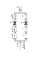
- FIG. 5 is a diagram showing an example of EMI prediction of a circuit with elements.
- FIG. 5 shows, as an example, an example of predicting the EMI intensity of the circuit C2 with elements using the trained EMI prediction model M2.
- the component ratio "0.5: 0.5" is referenced from the reference data.
- the circuit C2 with an element is divided into a circuit c21 corresponding to reflection and a circuit c22 corresponding to non-reflection.
- the EMI prediction of the circuit c21 corresponding to the reflection and the EMI prediction of the circuit c22 corresponding to the non-reflection are performed in parallel. That is, the current distribution I1 of the circuit c21 corresponding to the reflection is calculated by inputting the circuit information of the circuit c21 corresponding to the reflection into the circuit simulator. By inputting the current distribution I1 of the circuit c21 corresponding to the reflection calculated in this way to the EMI prediction model M2, the estimated value 210A of the EMI intensity can be obtained as the output of the EMI prediction model M2. Further, the current distribution I2 of the circuit c22 corresponding to non-reflection is calculated by inputting the circuit information of the circuit c22 corresponding to non-reflection into the circuit simulator.
- the estimated value 210B of the EMI intensity can be obtained as the output of the EMI prediction model M2.
- the estimated EMI intensity 210A and the estimated EMI intensity 210B are combined according to the ratio of the reflective component and the non-reflective component referred to from the reference data "0.5: 0.5", whereby the circuit C2 with an element is used.
- the estimated value 21 of the EMI intensity of is obtained.
- the EMI prediction of the circuit with elements can be realized by synthesizing the EMI prediction results of the circuit equivalent to reflection and the circuit equivalent to non-reflection. Therefore, according to the advanced technology 2, it is possible to reduce the training data of the circuit other than the circuit corresponding to the reflection and the circuit corresponding to the non-reflection per the circuit with one element. Further, the advanced technology 2 has a higher effect of reducing the number of training data in the domain of the EMI prediction model having more patterns of elements arranged in the circuit and their physical property values.
- the division and composition exemplified in the advanced technology 1 and the advanced technology 2 only support a single-line branch circuit or a circuit with elements, and are therefore difficult to apply to a multi-line circuit.
- crosstalk refers to an electromagnetic coupling caused by either a capacitive coupling or an inductive coupling.
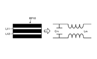
- FIG. 6 is a diagram showing an example of crosstalk occurrence.
- FIG. 6 shows a top view of the substrate BP10.
- the substrate BP10 includes two lines L11 and a line L12. These lines L11 and L12 are not connected as wiring of a circuit.
- a virtual capacitor called mutual capacitance Cm is formed.
- inductive coupling occurs, a virtual coil called mutual inductance Lm is formed.
- the mutual capacitance Cm and the mutual inductance Lm are electromagnetically coupled. In this case, the characteristic impedances of the line L11 and the line L12 change.
- the EMI also changes. Therefore, since the line L11 and the line L12 where crosstalk occurs are not equivalent to the synthesis of a single line, the division and synthesis exemplified in the advanced technology 1 and the advanced technology 2 cannot be applied.
- the prediction accuracy may decrease. For example, if only one of the circuits of a plurality of lines is supported, the current generated in the other lines is ignored, so that the accuracy of EMI prediction is lowered. From this, when trying to include a circuit of a plurality of lines in the domain to which the task of the above EMI prediction model is applied, the variation of the circuit to be predicted increases.
- a training data set containing a wide range of potential prediction targets is created, and the training of the machine learning model is executed using the training data set.
- the variation of the circuit to be predicted increases.
- 1000 training data are basically sampled as an example.
- the training data of 1000 cases of each line is sampled, if the combination of 1 line to 3 lines is included, 10 Estimated 3.003 million cases will be required.
- the modeling cost of the circuit information input to the circuit simulator and the calculation cost of the circuit simulator also increase.
- the training data generation function either generates the current distribution of the two lines by simulation according to the ratio of the distance between the two lines and the distance between the two lines and the GND layer, or generates the current distribution of each line. Training data is generated by switching whether to synthesize the current distribution.
- FIG. 7 is a diagram schematically showing the geometric shape of the circuit.
- FIG. 7 shows a side view of the substrate BP20 in which two lines L21 and lines L22 are arranged in parallel on the GND layer.
- the values of mutual capacitance (Cm) and mutual inductance (Lm) formed between the line L21 and the line L22 when crosstalk occurs are the distance s between the line L21 and the line L22 and the GND layer from the line L21 and the line L22. It is determined by the distance h to.
- the formula for calculating the mutual inductance (Lm) is as shown in the following formula (1). “ ⁇ ” in the following equation (1) indicates a magnetic constant.
- the formula for calculating the mutual capacitance (Cm) is as shown in the following formula (2). “ ⁇ ” in the following equation (2) refers to the permittivity. Further, “F” in the following formula (2) is expressed by the following formula (3). Further, “Fm” in the following formula (1) and the following formula (2) is expressed by the following formula (4).
- one of the points of focus in this embodiment is that the tracks where crosstalk does not occur can be regarded as the sum of the tracks. Only with such a point of view is a data extension that synthesizes the current distribution that has been calculated individually from each line before the simulation, instead of the simulation that calculates the current distribution of two lines that are not connected by crosstalk. Motivation to do.
- FIG. 8 is a diagram showing an application example of simulation and data expansion.
- FIG. 8 shows an example in which training data is generated from variations in the shape of each of the 1st to 3rd lines as an example. Further, FIG. 8 shows excerpts of circuits C11 to C13 as variations of the shape of one line. Further, FIG. 8 shows excerpts of the circuit C21 and the circuit C22 as variations of the shape of the two lines, and excerpts of the circuits C31 and C32 as variations of the shape of the three lines. Note that FIG. 8 shows a combination of lines that are not connected to each other via crosstalk among circuits of a plurality of lines by hatching.
- the circuit C11 is a single-line circuit
- a simulation for calculating the current distribution of the circuit C11 is performed by inputting the circuit information of the circuit C11 into the circuit simulator. Then, training data is generated from the current distribution of the circuit C11 calculated by the simulation.
- the circuit C12 is also a single-line circuit like the circuit C11
- training data is generated from the current distribution of the circuit C12 calculated by the simulation in the same manner as the circuit C11.
- the circuit C13 is also a single-line circuit like the circuit C11, training data is generated from the current distribution of the circuit C13 calculated by the simulation in the same manner as the circuit C11.
- circuit C21 crosstalk occurs between the two lines.
- a simulation for calculating the current distribution of the circuit C21 is performed by inputting the circuit information of the circuit C21 to the circuit simulator. Then, training data is generated from the current distribution of the circuit C21 calculated by the simulation.
- the circuit C22 since crosstalk does not occur between the two lines L221 and the line L222, there is room for data expansion.
- the circuit C22 can be regarded as the sum of the lines of the circuit C12 and the lines of the circuit C13. Therefore, training data is generated from the current distribution of the circuit C22 obtained by data expansion obtained by adding the calculated current distribution of the circuit C12 and the calculated circuit C13.
- the circuit C31 there is a line L311 and a line L312 that are not connected to each other via crosstalk, so there is room for data expansion.
- the circuit C31 can be regarded as the sum of the lines of the circuit C21 and the lines of the circuit C14 (not shown). Therefore, training data is generated from the current distribution of the circuit C31 obtained by data expansion obtained by adding the calculated current distribution of the circuit C21 and the calculated current distribution of the circuit C14.
- the circuit C32 since the three lines are connected to each other via crosstalk, there is no room for data expansion. In this case, a simulation for calculating the current distribution of the circuit C32 is performed by inputting the circuit information of the circuit C32 into the circuit simulator. Then, training data is generated from the current distribution of the circuit C32 calculated by the simulation.
- FIG. 9 is a diagram showing an example of data expansion.
- FIG. 9 illustrates, as an example, a data extension for generating training data from the circuit C22 shown in FIG. As shown in FIG. 9, the circuit C22 is divided into the circuit C221 and the circuit C222 with a portion where there is no crosstalk as a boundary.
- a circuit having a geometric shape similar to the geometric shape of the circuit C221 is searched from the circuit whose current distribution has been calculated by simulation. Since the circuit C12 is hit by such a search, the calculated current distribution I12 and EMI intensity P12 of the circuit C12 can be obtained.
- a circuit having a geometric shape similar to the geometric shape of the circuit C222 is searched from the circuit whose current distribution has been calculated by simulation. Since the circuit C13 is hit by such a search, the calculated current distribution I13 and EMI intensity P13 of the circuit C13 can be obtained.
- the current distribution I22 of the circuit C22 is generated by synthesizing the current distribution I12 of the circuit C12 and the current distribution I13 of the circuit C13.
- the EMI intensity P22 of the circuit C22 is generated by synthesizing the EMI intensity P12 of the circuit C12 and the EMI intensity P13 of the circuit C13.
- the training data generation function As described above, does the training data generation function according to this embodiment generate the current distribution of the two lines by simulation according to the ratio between the distance between the two lines and the distance between the two lines and the GND layer? , The training data is generated by switching whether to synthesize the current distribution of each line. For example, in the example shown in FIG. 8, two training data of the circuit C22 and the circuit C31 out of the seven circuits can be generated through data expansion. Therefore, it is possible to reduce the modeling cost of the circuit C22 and the circuit C31 input to the circuit simulator, and the cost of calculating the current distribution and the EMI intensity of the circuit C22 and the circuit C31 by the circuit simulator. Therefore, according to the training data generation function according to the present embodiment, it is possible to reduce the amount of calculation at the time of training data generation. For example, it is possible to reduce the number of simulation executions when generating training data for a circuit of a plurality of lines.
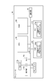
- FIG. 1 schematically shows a block corresponding to a function of the server device 10.
- the server device 10 has a communication interface unit 11, a storage unit 13, and a control unit 15.
- FIG. 1 only shows an excerpt of the functional part related to the above data generation function, and the functional part other than the figure, for example, the functional part that the existing computer is equipped with by default or as an option is a server. It may be provided in the device 10.
- the communication interface unit 11 corresponds to an example of a communication control unit that controls communication with another device, for example, a client terminal 30.
- the communication interface unit 11 can be realized by a network interface card such as a LAN card.
- the communication interface unit 11 receives a request for training data generation and various user settings related to the training data generation function from the client terminal 30. Further, the communication interface unit 11 outputs a set of training data generated by the training data generation function, a trained EMI prediction model, and the like to the client terminal 30.
- the storage unit 13 is a functional unit that stores various types of data.
- the storage unit 13 is realized by storage, for example, internal, external or auxiliary storage.
- the storage unit 13 stores the circuit information group 13A, the training data set 13B, and the model data 13M.
- the storage unit 13 can store various data such as account information of the user who receives the training data generation function.
- the explanation of the training data set 13B and the model data 13M will be described later together with the explanation of the generation unit 18 or the training unit 19.
- the circuit information group 13A is a set of n circuit information. For example, when an EMI prediction model of a circuit having a maximum of k lines is generated, n pieces are followed by procedures such as 1-line shape variation, 2-line shape variation, ..., K-line shape variation. The circuits of training data candidates are listed. The n circuit information corresponding to each of the n training data candidate circuits enumerated in this way is stored in the storage unit 13.
- the circuit information may include circuit geometry information, circuit connection information, and the like.
- the geometric shape information may include geometric shapes such as shapes and arrangements of lines, GND layers, and the like.
- the geometric shape may include coordinates such as a start point, an end point, a bending point, a relay point, and a branch point forming a line, as well as coordinates such as a vertex, a center of gravity point, and a center point forming a surface of the GND layer.
- coordinates may be two-dimensional coordinates corresponding to the surface of the substrate, but may be three-dimensional coordinates including axes in the layer direction, for example, in the vertical direction.
- the connection information includes a netlist used in a circuit simulator such as SPICE (Simulation Program with Integrated Circuit Emphasis).
- SPICE Simulation Program with Integrated Circuit Emphasis
- connection information can be acquired by importing from a design support program such as a CAD (Computer-Aided Design) system.
- the control unit 15 is a processing unit that controls the entire server device 10.
- the control unit 15 is realized by a hardware processor.
- the control unit 15 includes an acquisition unit 16, a determination unit 17, a generation unit 18, and a training unit 19.
- the acquisition unit 16 is a processing unit that acquires circuit information.
- the acquisition unit 16 can start the process when the request for training data generation is received from the client terminal 30.
- the acquisition unit 16 can also perform initial setting of various parameters related to the training data generation function as an example. For example, a crosstalk determination criterion to be compared with the ratio of the distance s between the two lines to the distance h from the line to the GND layer, for example, the threshold value d is set.
- the user setting received via the client terminal 30 may be applied to the threshold value d, or the system setting determined by the designer or the like of the training data generation function may be applied.
- the acquisition unit 16 acquires the circuit information of the circuits of n training data candidates by referring to the circuit information group 13A stored in the storage unit 13.
- the determination unit 17 is a processing unit that determines whether or not the relationship between the distance between the two lines included in the circuit information and the distance between the two lines and the GND layer satisfies the condition. As an example, the determination unit 17 pairs two independent lines among the lines included in the circuit of the training data candidate for each circuit of the training data candidate acquired by the acquisition unit 16. For example, assuming that the circuit of the training data candidate includes m lines, two n C pairs corresponding to the combination obtained by extracting two lines from the m lines are obtained. Then, the determination unit 17 calculates the shortest distance s of the two lines corresponding to the pair for each pair of nC . Then, the determination unit 17 determines whether or not the shortest distance s of the two lines is equal to or greater than the threshold value d, which is an example of the crosstalk determination criterion.
- 5 * h can be set as the threshold value d of the crosstalk determination criterion.
- the threshold value d of the crosstalk determination criterion can be determined to be 5 * h. In this case, if the shortest distance s is 5 * h or more, it is determined that crosstalk does not occur, while if it is not 5 * h or more, it is determined that crosstalk occurs.
- the threshold value d of the crosstalk determination criterion may be an arbitrary value set by the user regardless of the system setting.
- FIG. 10 is a diagram showing an example of crosstalk determination.
- FIG. 10 shows, as an example, an example of determining the crosstalk of the circuit C31.
- the circuit C31 includes three lines L311, a line L312 and a line L313.
- the presence or absence of crosstalk is determined for each pair of 3C 2 corresponding to the combination obtained by extracting two lines from the three lines L311, L312 and L313.
- the pair of the line L311 and the line L313 is extracted as the circuit C311
- the pair of the line L311 and the line L312 is extracted as the circuit C312, and the pair of the line L312 and the line L313 is used.
- circuit C313 An excerpt is shown as circuit C313. As shown in circuit C311 the pair of line L311 and line L313 is determined to have crosstalk. On the other hand, as shown in the circuit C312 and the circuit C313, the pair of the line L311 and the line L312 is determined to have no crosstalk, and the pair of the line L312 and the line L313 is also determined to have no crosstalk.
- the determination unit 17 determines whether or not there are lines that cannot reach each other via crosstalk in the circuit of the training data candidate being selected. Then, when there are lines that cannot be reached from each other via crosstalk, it is found that the circuit of the training data candidate has room for applying data extension. In this case, the selected training data candidate circuit is added to the list of data expansion candidates among the list of data expansion candidates and the list of simulation candidates stored in a storage area such as a memory or storage (not shown). On the other hand, if there are no lines that are inaccessible to each other via crosstalk, it turns out that there is no room for data extension in the training data candidate circuit. In this case, the selected training data candidate circuit is added to the list of simulation candidates.
- the line L311 and the line L313 are connected via crosstalk.
- crosstalk does not occur between the pair of the line L311 and the line L312 and the pair of the line L312 and the line L313. Therefore, it is impossible to reach the line L312 via either the line L311 or the line L313. Therefore, the line L311 and the line L313 and the line L312 are identified as unreachable.
- the determination unit 17 has a circuit having a geometric shape that matches the geometric shape of the partial line for each partial line that cannot be reached via crosstalk in the list of simulation candidates. Further determine whether or not.
- the determination unit 17 divides the circuit of the training data candidate into a partial line for each circuit of the training data candidate included in the list of data expansion candidates.
- FIG. 11 is a diagram showing an example of a method of dividing into partial lines.
- FIG. 11 shows an example in which the circuit C31 shown in FIG. 10 is divided into partial lines.
- the pair determined to have crosstalk is the line L311 and the line L313, and the other pair is determined to have no crosstalk.
- the virtual line V1 is set for the pair of the line L311 and the line L313 determined to have crosstalk.
- the virtual line V1 is set at a position connecting the shortest distance s of the line L311 and the line L313.
- the circuit C31 is divided into a place where there is no connection, for example, a pair determined to have no crosstalk as a boundary.
- it is divided into a partial line C311 including the line L311 and the line L313, and a C312 including the line L312. Then, the virtual line V1 set before the division is deleted.
- the division into partial lines is realized by searching for lines that are inaccessible to each other via crosstalk.
- crosstalk occurs between line A and line B, crosstalk does not occur between line A and line C, and , It is assumed that cross talk does not occur between the line B and the line C.
- the connection relationship including the electromagnetic connection is (AB, C). Therefore, the circuit is divided into a partial line AB and a partial line C.
- crosstalk occurs between line A and line B, and crosstalk also occurs between line B and line C. Further, it is assumed that cross talk does not occur between the line A and the line C.
- the connection relationship including the electromagnetic connection is (ABC)
- the circuit cannot be divided into partial lines.
- the determination unit 17 searches the list of simulation candidates for a circuit having a geometric shape that matches the geometric shape of the partial line for each partial line.
- Such geometrical matching is a feature point that forms a line between the line and the partial line of the training data candidate circuit stored in the list of simulation candidates, such as start and end points, bend points, relay points, and branches. This can be achieved by matching coordinates such as points.
- the matching of geometric shapes is taken as an example here, it is not always necessary to make an exact match, provided that the similarity is equal to or higher than the threshold value, or the distance or dissimilarity is within the threshold value. You can also perform matching.
- the determination unit 17 shifts the circuit of the training data candidate that is the division source from the list of data expansion candidates to the list of simulation candidates. That is, the circuit entry of the training data candidate is deleted from the list of data extension candidates, and the entry is added to the list of simulation candidates.
- the circuit of the training data candidate that is the division source is insufficient for synthesis during data expansion. Turns out not. In this case, the transition from the list of data extension candidates to the list of simulation candidates is not performed.
- the generation unit 18 is a processing unit that generates training data corresponding to the circuit of the training data candidate. As shown in FIG. 1, the generation unit 18 has a simulation unit 18A and a data expansion unit 18B.
- the simulation unit 18A is a processing unit that generates training data by simulation.
- the simulation unit 18A executes the following processing for each training data candidate circuit stored in the simulation candidate list. That is, the simulation unit 18A executes a simulation for calculating the current distribution and the EMI intensity of the circuit by inputting the circuit information of the training data candidate circuit into the circuit simulator.
- the circuit simulator is executed on the server device 10, but the circuit simulator may be executed by an arbitrary execution subject. For example, an API (Application Programming Interface) published by an external device, service, or software that executes a circuit simulator can be used to request calculation of current distribution and EMI intensity. After that, the simulation unit 18A generates training data associated with the current distribution and the EMI intensity obtained by the simulation.
- API Application Programming Interface
- the circuit simulator calculates the current distribution for each frequency component included in a specific frequency domain based on the input circuit information.
- a current distribution image of the circuit calculated by the circuit simulator for example, a current distribution image in which the intensity of the current flowing on the substrate surface is mapped on a two-dimensional map can be obtained for each frequency component.
- the simulation unit 18A identifies one or a plurality of resonance frequencies at which the maximum value of the current distribution calculated for each frequency component has a maximum.
- the simulation unit 18A processes the pixel values of the pixels included in the current distribution image corresponding to the resonance frequency based on the distance from the line of each pixel from the aspect of approximating the near field of the electronic circuit. To execute. For example, as the current flowing on the line increases, the shading value approaches the upper limit value, for example, 255 corresponding to white, while as the current decreases, the shading value approaches the lower limit value, for example, 0 corresponding to black.
- the current distribution image generated by this is taken as an example. In this case, as the distance from the line of the pixel included in the current distribution image becomes smaller, the shift amount for shifting the shading value of the pixel to the upper limit value side is set larger.
- the shift amount for shifting the shading value of the pixel to the lower limit value side is set smaller.
- the simulation unit 18A generates training data in which the resonance frequency and current distribution image and the EMI intensity are associated with each other.
- the resonance frequency which is a scalar value
- the resonance frequency is converted into a matrix that can be input to a standard neural network as an example of the EMI prediction model.
- a matrix corresponding to the two-dimensional array of the current distribution image is generated from the aspect of unifying the matrix of each channel to the same type.
- the value of the resonance frequency is embedded in each element of the matrix. Training data in which the matrix and the current distribution image (matrix) in which the resonance frequency generated in this way is embedded and the EMI intensity which is the correct label are associated with each other is generated.
- the data expansion unit 18B is a processing unit that generates training data by data expansion.
- the data expansion unit 18B executes the following processing for each training data candidate circuit stored in the data expansion list in the order in which the data expansion is registered in the list. That is, the data expansion unit 18B divides the training data candidate circuit into partial lines. Then, the data expansion unit 18B selects a circuit having a geometric shape similar to the geometric shape of the partial line from the circuits in which the training data is generated by the simulation unit 18A for each partial line obtained by the division. search for. After that, the data expansion unit 18B acquires the calculation results of the current distribution and the EMI intensity for each partial line as the simulation results corresponding to the circuits hit by the search.
- the data expansion unit 18B generates the current distribution of the circuit of the training data candidate by synthesizing the current distribution acquired for each sub-line between each sub-line. Further, the data expansion unit 18B generates the EMI intensity of the circuit of the training data candidate by synthesizing the EMI intensity acquired for each partial line between the partial lines. Then, the data expansion unit 18B generates training data for the circuit of the training data candidate by associating the current distribution after synthesis with the EMI intensity of the synthetic word.
- the generation unit 18 registers the set of the training data generated for each circuit information in the storage unit 13 as the training data set 13B. do.
- the training unit 19 is a processing unit that trains an EMI prediction model using training data for machine learning.
- the training unit 19 may use the training unit 19. Perform the following processing. That is, the training unit 19 trains the EMI prediction model with the current distribution of the training data included in the training data set 13B as the feature quantity and the EMI intensity as the objective variable.
- the training unit 19 inputs the resonance frequency corresponding to the input data of channel 1 and the current distribution image corresponding to the input data of channel 2 into the EMI prediction model. As a result, an estimated value of EMI intensity is obtained as the output of the EMI prediction model.
- the training unit 19 updates the parameters of the EMI prediction model based on the loss between the estimated value of the EMI intensity output by the EMI prediction model and the EMI intensity of the correct label. This gives a trained EMI prediction model.
- model data 13M The data related to the trained EMI prediction model obtained in this way is stored in the storage unit 13 as model data 13M.
- the model data 13M includes the layer structure of the machine learning model such as neurons and synapses of each layer of the input layer, the hidden layer, and the output layer, and the weights and biases of each layer.
- Machine learning model parameters may be included.
- model providing service may be performed by providing the model data of the trained EMI prediction model to the client terminal 30, or the EMI prediction for predicting the EMI intensity of the circuit using the trained EMI prediction model. Services may be provided.
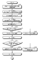
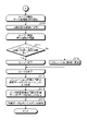
- 12 and 13 are flowcharts showing the procedure of the training data generation process according to the first embodiment. As one aspect, this process can be started when a request for training data generation is received from the client terminal 30.
- the acquisition unit 16 acquires circuit information of n training data candidate circuits by referring to the circuit information group 13A stored in the storage unit 13 (step S101).
- the determination unit 17 starts the loop process 1 that repeats the processes from step S102 to step S109 for the number of times corresponding to the number of circuits of n training data candidates acquired in step S101.
- the processing from step S102 to step S106 may be executed in parallel.
- the determination unit 17 pairs two independent lines among the lines included in the circuit of the training data candidate during the loop processing (step S102). For example, assuming that the circuit of the training data candidate includes m lines, two n C pairs corresponding to the combination obtained by extracting two lines from the m lines are obtained.
- the determination unit 17 starts the loop process 2 that repeats the processes from step S103 to step S106 for the number of times corresponding to the pair of two nCs obtained by the pairing in step S102.
- the processing from step S103 to step S106 may be executed in parallel.
- the determination unit 17 calculates the shortest distance s of the two lines corresponding to the pair during the loop processing (step S103). Then, the determination unit 17 determines whether or not the shortest distance s between the two lines is equal to or greater than the crosstalk determination criterion d (step S104).
- step S104Yes when the shortest distance s is equal to or greater than the crosstalk determination criterion d (step S104Yes), it is identified that crosstalk does not occur (step S105).
- step S104No when the shortest distance s is not equal to or greater than the crosstalk determination criterion d (step S104No), it is identified that crosstalk occurs (step S106).
- the determination unit 17 determines whether or not there are lines that cannot reach each other via crosstalk in the circuit of the training data candidate during the loop processing (step S107). Then, when there are lines that cannot be reached from each other via crosstalk (step S107Yes), it is found that there is room for applying data expansion to the circuit of the training data candidate. In this case, the circuit of the training data candidate during the loop processing is added to the list of data expansion candidates (step S108).
- step S107No when there are no lines that cannot be reached from each other via crosstalk (step S107No), it is found that there is no room for applying data expansion to the circuit of the training data candidate. In this case, the circuit of the training data candidate during the loop processing is added to the list of simulation candidates (step S109).
- the determination unit 17 starts the loop process 3 that repeats the processes from step S110 to step S112 shown in FIG. 13 for the number of times corresponding to the number of circuits of the training data candidates included in the list of data expansion candidates.
- the processing from step S110 to step S112 may be executed in parallel.
- the determination unit 17 divides the circuit of the training data candidate during the loop processing into partial lines (step S110). After that, the loop process 4 that repeats the processes of steps S111 and S112 is started for the number of times corresponding to the number of partial lines obtained by the division of step S110. Although an example in which the loop processing is performed is given here, the processing of step S111 and step S112 may be executed in parallel.
- the determination unit 17 searches the list of simulation candidates for a circuit having a geometric shape that matches the geometric shape during loop processing. At this time, if there is even one partial line that does not hit the search for a circuit having a geometric shape that matches the geometric shape of the partial line (step S111No), the training data candidate circuit that is the division source is combined during data expansion. It turns out that there is a shortage of circuits to use. In this case, the determination unit 17 shifts the circuit of the training data candidate that is the division source from the list of data expansion candidates to the list of simulation candidates (step S112).
- step S111No when there is no partial line that does not hit the search for a circuit having a geometric shape that matches the geometric shape of the partial line (step S111No), the circuit of the training data candidate that is the division source is used for synthesis at the time of data expansion. It turns out that there is no shortage. In this case, the transition from the list of data extension candidates to the list of simulation candidates is not performed.
- step S111 When the loop process 4 of step S111 is completed, it is identified whether or not it is necessary to shift from the list of data expansion candidates of the circuit of the training data candidate to be the division source to the list of simulation candidates. Then, when the loop process 3 from step S110 to step S112 is completed, the confirmation of migration regarding the circuits of all the training data candidates included in the list of data expansion candidates is completed.
- the simulation unit 18A generates training data of the circuit of the training data candidate stored in the list of simulation candidates by simulation (step S113).
- the data expansion unit 18B generates training data of the circuit of the training data candidate stored in the list of data expansion candidates by data expansion (step S114).
- the training unit 19 trains the EMI prediction model (step S115) with the current distribution of the training data generated in step S113 or step S114 as the feature quantity and the EMI intensity as the objective variable, and ends the process. ..
- the training data generation function generates a current distribution of two lines by simulation according to the ratio of the distance between the two lines and the distance between the two lines and the GND layer.
- Training data is generated by switching between synthesizing the current distribution of each line.
- the patterns in which training data can be generated by simulation are as follows. That is, the lines A only, the line B only, the line C only, the lines A and B (coupling), the lines A and C (coupling), the lines B and C (coupling), and the lines A and B and C (coupling).
- the patterns to which data expansion can be applied are, at the maximum, lines A and B (uncoupled), lines A and C (uncoupled), lines B and C (uncoupled), and lines A and B and C. (Only A and B are connected), lines A and B and C (only A and C are connected), and lines A and B and C (only B and C are connected). Therefore, according to the training data generation function according to the present embodiment, it is possible to reduce the amount of calculation at the time of training data generation. For example, it is possible to reduce the number of simulation executions when generating training data for a circuit of a plurality of lines.
- each component of each of the illustrated devices does not necessarily have to be physically configured as shown in the figure. That is, the specific form of distribution / integration of each device is not limited to the one shown in the figure, and all or part of them may be functionally or physically distributed / physically distributed in any unit according to various loads and usage conditions. Can be integrated and configured.
- the acquisition unit 16, the determination unit 17, the generation unit 18, or the training unit 19 may be connected via a network as an external device of the server device 10. Further, even if another device has the acquisition unit 16, the determination unit 17, the generation unit 18, or the training unit 19, and is connected to a network and cooperates with each other, the function of the server device 10 may be realized. good.
- FIG. 14 is a diagram showing an example of computer hardware configuration.
- the computer 100 has an operation unit 110a, a speaker 110b, a camera 110c, a display 120, and a communication unit 130. Further, the computer 100 has a CPU 150, a ROM 160, an HDD 170, and a RAM 180. Each of these 110 to 180 parts is connected via the bus 140.
- a CPU is taken as an example of a hardware processor, but the present invention is not limited to this. That is, it is not limited to a general-purpose processor such as a CPU or MPU, but may be a DLU (Deep Learning Unit), a GPGPU (General-Purpose computing on Graphics Processing Units), a GPU cluster, or the like.
- a general-purpose processor such as a CPU or MPU, but may be a DLU (Deep Learning Unit), a GPGPU (General-Purpose computing on Graphics Processing Units), a GPU cluster, or the like.
- the HDD 170 stores a training data generation program 170a that has the same functions as the acquisition unit 16, the determination unit 17, the generation unit 18, and the training unit 19 shown in the first embodiment. ..
- the training data generation program 170a may be integrated or separated as in the components of the acquisition unit 16, the determination unit 17, the generation unit 18, and the training unit 19 shown in FIG. That is, not all the data shown in FIG. 1 may be stored in the HDD 170, and the data used for processing may be stored in the HDD 170.
- the CPU 150 reads the training data generation program 170a from the HDD 170 and then deploys it to the RAM 180.
- the training data generation program 170a functions as the training data generation process 180a as shown in FIG.
- the training data generation process 180a expands various data read from the HDD 170 into the area allocated to the training data generation process 180a in the storage area of the RAM 180, and executes various processes using the expanded various data. ..
- the process shown in FIGS. 12 and 13 is included.
- the CPU 150 not all the processing units shown in the first embodiment need to operate, and it is sufficient that the processing units corresponding to the processes to be executed are virtually realized.
- the above training data generation program 170a does not necessarily have to be stored in the HDD 170 or ROM 160 from the beginning.
- each program is stored in a "portable physical medium" such as a flexible disk inserted into the computer 100, a so-called FD, a CD-ROM, a DVD disk, a magneto-optical disk, or an IC card. Then, the computer 100 may acquire and execute each program from these portable physical media. Further, each program is stored in another computer or server device connected to the computer 100 via a public line, the Internet, a LAN, a WAN, or the like, and the computer 100 acquires and executes each program from these. You may do it.
Abstract
This training data generation program causes a computer to perform a process for: acquiring circuit information; determining whether or not the relationship between the distance between two lines included in the circuit information and the distance between the two lines and a GND layer meets a condition; and, if the relationship meets the condition, using a simulation to generate first current distribution information associated with the two lines and generating machine learning training data on the basis of the first current distribution information, or if the relationship does not meet the condition, combining sets of current distribution information respectively associated with the two lines to generate second current distribution information associated with the two lines and generating machine learning training data on the basis of the second current distribution information.
Description
本発明は、訓練データ生成技術に関する。
The present invention relates to a training data generation technique.
電子回路におけるEMI(Electromagnetic Interference)予測に機械学習技術が用いられる。ここでEMIとは、電子回路から放射される電磁波放射状況を指す。また、EMIは、電磁波放射状況のうち遠方の電磁界の状況を指す側面から遠方界とも呼ばれる。
Machine learning technology is used for EMI (Electromagnetic Interference) prediction in electronic circuits. Here, EMI refers to the electromagnetic wave radiation state radiated from an electronic circuit. In addition, EMI is also referred to as a distant field from the aspect of the electromagnetic wave radiation situation, which refers to the distant electromagnetic field situation.
例えば、回路情報と、当該回路情報に対する電磁波解析のシミュレーション結果とが対応付けられた訓練データから生成される訓練済みの機械学習モデルを用いて、予測対象とする回路におけるEMI強度が予測される。
For example, the EMI intensity in the circuit to be predicted is predicted using a trained machine learning model generated from the training data in which the circuit information and the simulation result of the electromagnetic wave analysis for the circuit information are associated with each other.
しかしながら、上記の機械学習モデルによりEMI強度を予測する場合、回路の線路数が増加するのに伴って予測対象とする回路のバリエーションが増大するので、訓練データ生成時の計算量も膨大となる。
However, when the EMI intensity is predicted by the above machine learning model, the variation of the circuit to be predicted increases as the number of circuit lines increases, so that the amount of calculation at the time of training data generation becomes enormous.
1つの側面では、本発明は、訓練データ生成時の計算量の削減を実現できる訓練データ生成プログラム、訓練データ生成方法及び訓練データ生成装置を提供することを目的とする。
In one aspect, it is an object of the present invention to provide a training data generation program, a training data generation method, and a training data generation device that can realize a reduction in the amount of calculation at the time of training data generation.
1つの案では、訓練データ生成プログラムは、回路情報を取得し、回路情報に含まれる2つの線路間の距離と、前記2つの線路とGND層との距離との関係が条件を満たすか否かを判定し、前記関係が前記条件を満たす場合、シミュレーションにより前記2つの線路に対応する第1の電流分布情報を生成し、前記第1の電流分布情報に基づいて機械学習用の訓練データを生成し、前記関係が前記条件を満たさない場合、前記2つの線路のそれぞれに対応する電流分布情報を合成して前記2つの線路に対応する第2の電流分布情報を生成し、前記第2の電流分布情報に基づいて機械学習用の訓練データを生成する、処理をコンピュータに実行させる。
In one proposal, the training data generation program acquires circuit information, and whether or not the relationship between the distance between the two lines included in the circuit information and the distance between the two lines and the GND layer satisfies the condition. If the relationship satisfies the above conditions, the first current distribution information corresponding to the two lines is generated by simulation, and the training data for machine learning is generated based on the first current distribution information. When the relationship does not satisfy the above conditions, the current distribution information corresponding to each of the two lines is combined to generate the second current distribution information corresponding to the two lines, and the second current is generated. Generates training data for machine learning based on distribution information, and causes a computer to perform processing.
訓練データ生成時の計算量の削減を実現できる。
It is possible to reduce the amount of calculation when generating training data.
以下に添付図面を参照して本願に係る訓練データ生成プログラム、訓練データ生成方法及び訓練データ生成装置について説明する。なお、この実施例は開示の技術を限定するものではない。そして、各実施例は、処理内容を矛盾させない範囲で適宜組み合わせることが可能である。
The training data generation program, training data generation method, and training data generation device according to the present application will be described below with reference to the attached drawings. It should be noted that this embodiment does not limit the disclosed technology. Then, each embodiment can be appropriately combined as long as the processing contents do not contradict each other.
図1は、実施例1に係るサーバ装置10の機能的構成の一例を示すブロック図である。図1に示すサーバ装置10は、電子回路におけるEMI強度を予測する機械学習モデルの訓練に用いる訓練データを生成する訓練データ生成機能を提供するコンピュータの一例である。以下、電子回路におけるEMI強度を予測する機械学習モデルのことを「EMI予測モデル」と記載する場合がある。
FIG. 1 is a block diagram showing an example of the functional configuration of the server device 10 according to the first embodiment. The server device 10 shown in FIG. 1 is an example of a computer that provides a training data generation function for generating training data used for training a machine learning model that predicts EMI intensity in an electronic circuit. Hereinafter, a machine learning model for predicting EMI intensity in an electronic circuit may be referred to as an “EMI prediction model”.
このような訓練データ生成機能は、上記の訓練データを用いてEMI予測モデルの機械学習を実行する機械学習サービスの一機能としてパッケージ化され得る。この他、上記の訓練データ生成機能、或いは上記の機械学習サービスは、訓練済みのEMI予測モデルを提供するモデル提供サービス、或いは訓練済みのEMI予測モデルを用いて回路のEMI強度を予測するEMI予測サービスの一機能としてパッケージ化され得る。さらに、上記のモデル提供サービス、あるいは上記のEMI予測サービスは、電磁波解析のシミュレーションを実行するシミュレーションサービスの一機能としてパッケージ化され得る。
Such a training data generation function can be packaged as a function of a machine learning service that executes machine learning of an EMI prediction model using the above training data. In addition, the above-mentioned training data generation function or the above-mentioned machine learning service is a model providing service that provides a trained EMI prediction model, or an EMI prediction that predicts the EMI intensity of a circuit using a trained EMI prediction model. It can be packaged as a function of the service. Further, the above-mentioned model providing service or the above-mentioned EMI prediction service can be packaged as a function of a simulation service for executing a simulation of electromagnetic wave analysis.
例えば、サーバ装置10は、上記の訓練データ生成機能を実現する訓練データ生成プログラムを任意のコンピュータにインストールさせることにより実装できる。一例として、サーバ装置10は、上記の訓練データ生成機能をオンプレミスに提供するサーバとして実装することができる。他の一例として、サーバ装置10は、SaaS(Software as a Service)型のアプリケーションとして実装することで、上記の訓練データ生成機能をクラウドサービスとして提供することもできる。
For example, the server device 10 can be implemented by installing a training data generation program that realizes the above training data generation function on an arbitrary computer. As an example, the server device 10 can be implemented as a server that provides the above training data generation function on-premises. As another example, the server device 10 can be implemented as a SaaS (Software as a Service) type application to provide the above training data generation function as a cloud service.
また、サーバ装置10は、図1に示すように、ネットワークNWを介して、クライアント端末30と通信可能に接続され得る。例えば、ネットワークNWは、有線または無線を問わず、インターネットやLAN(Local Area Network)などの任意の種類の通信網であってよい。
Further, as shown in FIG. 1, the server device 10 can be communicably connected to the client terminal 30 via the network NW. For example, the network NW may be any kind of communication network such as the Internet or LAN (Local Area Network) regardless of whether it is wired or wireless.
クライアント端末30は、上記の訓練データ生成機能の提供を受けるコンピュータの一例である。例えば、クライアント端末30には、パーソナルコンピュータなどのデスクトップ型のコンピュータなどが対応し得る。これはあくまで一例に過ぎず、クライアント端末30は、ラップトップ型のコンピュータや携帯端末装置、ウェアラブル端末などの任意のコンピュータであってよい。
The client terminal 30 is an example of a computer that receives the above training data generation function. For example, the client terminal 30 may be supported by a desktop computer such as a personal computer. This is only an example, and the client terminal 30 may be any computer such as a laptop computer, a mobile terminal device, or a wearable terminal.
なお、図1には、上記の訓練データ生成機能がクライアントサーバシステムで提供される例を挙げるが、この例に限定されず、スタンドアロンで上記の訓練データ生成機能が提供されることとしてもよい。
Note that FIG. 1 shows an example in which the above training data generation function is provided by the client-server system, but the present invention is not limited to this example, and the above training data generation function may be provided standalone.
上記のEMI予測は、1つの側面として、電子回路基板の設計、いわゆる回路設計に有用な一面がある。すなわち、回路設計では、規格や法規制の面から、回路で観測される放射電磁波が周波数ごとに定められた規定値以内に収めることの関心が高い。このことから、回路設計では、電磁波解析のシミュレーションによりEMI予測が行われる。ところが、シミュレーションの実施には、回路のモデリングコストやシミュレータの計算コストなどの要因がハードルとなる。
The above EMI prediction has one aspect that is useful for the design of electronic circuit boards, so-called circuit design. That is, in circuit design, there is a great deal of interest in keeping the radiated electromagnetic waves observed in the circuit within the specified values set for each frequency from the viewpoint of standards and regulations. For this reason, in circuit design, EMI prediction is performed by simulation of electromagnetic field analysis. However, factors such as circuit modeling costs and simulator calculation costs are hurdles for implementing simulations.
このような背景から、ニューラルネットワーク、例えばCNN(Convolutional Neural Network)等の機械学習技術が用いられる。例えば、上記の背景技術の欄で説明した通り、回路情報と、当該回路情報に対する電磁波解析のシミュレーション結果とが対応付けられた訓練データから生成される訓練済みのEMI予測モデルを用いて、解析対象の回路におけるEMI強度が予測される。
Against this background, neural networks, such as machine learning technologies such as CNN (Convolutional Neural Network), are used. For example, as explained in the background technology section above, an analysis target is used using a trained EMI prediction model generated from training data in which circuit information and simulation results of electromagnetic field analysis for the circuit information are associated with each other. The EMI intensity in the circuit is predicted.
このようにEMI予測モデルを用いて回路のEMI強度を予測する場合、EMI予測の精度が一定の水準に達するためには、EMIに影響を与える回路の特徴が抽出された訓練データがEMI予測モデルの訓練に用いられることが条件となる。
When predicting the EMI intensity of a circuit using the EMI prediction model in this way, in order for the accuracy of the EMI prediction to reach a certain level, the training data from which the characteristics of the circuit that affect the EMI are extracted is the EMI prediction model. The condition is that it is used for training.
しかしながら、EMIに影響を与える回路の特徴には、様々なものがある。例えば、回路上に配置される線路の形状、あるいは回路の線路上の素子、例えば抵抗やコイル、コンデンサなどの配置が挙げられる。したがって、上記のEMI予測の訓練には、膨大な量の訓練データが必要となる。
However, there are various characteristics of the circuit that affect EMI. For example, the shape of the line arranged on the circuit, or the arrangement of elements on the line of the circuit, such as resistors, coils, and capacitors. Therefore, training for the above EMI prediction requires a huge amount of training data.
このことから、訓練データ数の削減を実現する技術として、先進技術1および先進技術2がある。ここで挙げる先進技術1および先進技術2は、公知である特許文献や非特許文献等に記載がある従来技術とは区別される。
For this reason, there are advanced technology 1 and advanced technology 2 as technologies for reducing the number of training data. The advanced technology 1 and the advanced technology 2 mentioned here are distinguished from the prior art described in known patent documents, non-patent documents, and the like.
先進技術1では、回路に配線された線路の分岐の有無に応じて回路が「単純回路」と「複雑回路」が分類される。例えば、回路のうち分岐がない回路が「単純回路」に分類される一方で、分岐がある回路が「複雑回路」に分類される。このような分類の下、先進技術1では、複雑回路は単純回路の組合せで表現できるという着眼点が訓練データ数の削減という課題の解決に活用される。
In Advanced Technology 1, the circuit is classified into "simple circuit" and "complex circuit" according to the presence or absence of branching of the line wired to the circuit. For example, a circuit without a branch is classified as a "simple circuit", while a circuit with a branch is classified as a "complex circuit". Under such a classification, in the advanced technology 1, the point of view that a complicated circuit can be expressed by a combination of simple circuits is utilized for solving the problem of reducing the number of training data.
図2は、単純回路および複雑回路の一例を示す図である。図2には、一例として、複雑回路C1が示されると共に、当該複雑回路C1に対応する単純回路の組合せの一例として、単純回路c1および単純回路c2が示されている。図2に示すように、複雑回路C1は、分岐点b1を境界にして単純回路c11および単純回路c12へ分割できる。この場合、分岐点b1から分岐する3つの部分線路のうち、励振源ES1を含む部分線路と、励振源ES1を含まない部分線路の各々との組合せを単純回路c11および単純回路c12の線路として複雑回路C1が分割される。これら単純回路c11および単純回路c12が合成されることにより複雑回路C1が得られるのは勿論のこと、単純回路c11のEMI強度200Aおよび単純回路c12のEMI強度200Bが合成されることにより複雑回路C1のEMI強度20が得られる。
FIG. 2 is a diagram showing an example of a simple circuit and a complicated circuit. In FIG. 2, a complex circuit C1 is shown as an example, and a simple circuit c1 and a simple circuit c2 are shown as an example of a combination of simple circuits corresponding to the complicated circuit C1. As shown in FIG. 2, the complex circuit C1 can be divided into the simple circuit c11 and the simple circuit c12 with the branch point b1 as a boundary. In this case, the combination of each of the partial line including the excitation source ES1 and the partial line not including the excitation source ES1 among the three partial lines branching from the branch point b1 is complicated as the line of the simple circuit c11 and the simple circuit c12. The circuit C1 is divided. The complex circuit C1 can be obtained by synthesizing the simple circuit c11 and the simple circuit c12, and the complex circuit C1 can be obtained by synthesizing the EMI strength 200A of the simple circuit c11 and the EMI strength 200B of the simple circuit c12. EMI strength 20 is obtained.
図3は、EMI予測モデルの機械学習方法の一例を示す図である。図3に示すように、EMI予測モデルM1の機械学習には、訓練データセットDS1が用いられる。例えば、訓練データセットDS1は、単純回路c11~cNの回路情報と、単純回路c11~cNの各々で観測されるEMI強度400A~400Nとが対応付けられた訓練データの集合である。ここで言う「回路情報」には、電子回路に含まれる素子の回路網の情報、例えばネットリストなどが含まれ得る。また、ここで言う「EMI強度」は、あくまで一例として、特定の周波数ドメインにおけるEMI強度の分布、いわゆるEMIスペクトルであってよい。
FIG. 3 is a diagram showing an example of a machine learning method of an EMI prediction model. As shown in FIG. 3, the training data set DS1 is used for machine learning of the EMI prediction model M1. For example, the training data set DS1 is a set of training data in which the circuit information of the simple circuits c11 to cN and the EMI intensities 400A to 400N observed in each of the simple circuits c11 to cN are associated with each other. The "circuit information" referred to here may include information on the network of elements included in the electronic circuit, for example, a netlist. Further, the "EMI intensity" referred to here may be, as an example, a distribution of EMI intensity in a specific frequency domain, a so-called EMI spectrum.
例えば、単純回路c11の回路情報がEMI予測モデルm1へ入力された場合、EMI予測モデルm1からEMI強度300Aが出力される。同様に、単純回路c12~cNの回路情報がEMI予測モデルm1へ入力されることにより、EMI予測モデルm1からEMI強度300B~300Nの出力が得られる。その上で、EMI予測モデルm1の出力であるEMI強度300B~300Nと、正解ラベルのEMI強度400A~400Nとの損失に基づいてEMI予測モデルm1のパラメータが更新される。このように、単純回路c11~cNの回路情報を特徴量、いわゆる説明変数とし、EMI強度を目的変数として、EMI予測モデルm1の機械学習が実行される。これにより、単純回路のEMI予測を実現する訓練済みのEMI予測モデルM1が得られる。
For example, when the circuit information of the simple circuit c11 is input to the EMI prediction model m1, the EMI intensity 300A is output from the EMI prediction model m1. Similarly, by inputting the circuit information of the simple circuits c12 to cN into the EMI prediction model m1, an output with an EMI intensity of 300B to 300N can be obtained from the EMI prediction model m1. Then, the parameters of the EMI prediction model m1 are updated based on the loss between the EMI strengths of 300B to 300N, which is the output of the EMI prediction model m1, and the EMI strengths of 400A to 400N of the correct label. In this way, machine learning of the EMI prediction model m1 is executed with the circuit information of the simple circuits c11 to cN as feature quantities, so-called explanatory variables, and the EMI intensity as the objective variable. As a result, a trained EMI prediction model M1 that realizes EMI prediction of a simple circuit is obtained.
図4は、複雑回路のEMI予測の一例を示す図である。図4には、一例として、図3に示された訓練済みのEMI予測モデルM1を用いて複雑回路C1のEMI強度を予測する事例が示されている。図4に示すように、複雑回路C1が予測対象とされる場合、複雑回路C1は、分岐点b1を境界にして単純回路c11および単純回路c12へ分割される。その後、単純回路c11のEMI予測および単純回路c12のEMI予測が並行して実施される。すなわち、単純回路c11の回路情報をEMI予測モデルM1へ入力することによりEMI予測モデルM1の出力としてEMI強度の推定値200Aが得られる。また、単純回路c12の回路情報をEMI予測モデルM1へ入力することによりEMI予測モデルM1の出力としてEMI強度の推定値200Bが得られる。これらEMI強度の推定値200AおよびEMI強度の推定値200Bが合成されることにより、複雑回路C1のEMI強度の推定値20が得られる。
FIG. 4 is a diagram showing an example of EMI prediction of a complicated circuit. FIG. 4 shows, as an example, an example of predicting the EMI intensity of the complex circuit C1 using the trained EMI prediction model M1 shown in FIG. As shown in FIG. 4, when the complex circuit C1 is the prediction target, the complex circuit C1 is divided into the simple circuit c11 and the simple circuit c12 with the branch point b1 as a boundary. After that, the EMI prediction of the simple circuit c11 and the EMI prediction of the simple circuit c12 are performed in parallel. That is, by inputting the circuit information of the simple circuit c11 into the EMI prediction model M1, the estimated value 200A of the EMI intensity can be obtained as the output of the EMI prediction model M1. Further, by inputting the circuit information of the simple circuit c12 into the EMI prediction model M1, the estimated value 200B of the EMI intensity can be obtained as the output of the EMI prediction model M1. By synthesizing the estimated value 200A of the EMI intensity and the estimated value 200B of the EMI intensity, the estimated value 20 of the EMI intensity of the complex circuit C1 is obtained.
このように、先進技術1では、単純回路用のEMI予測モデルM1による単純回路のEMI予測の結果を合成することにより複雑回路のEMI予測を実現できる。このため、先進技術1によれば、複雑回路の訓練データを削減できる。さらに、先進技術1では、回路の線路の分岐パターンが多いEMI予測モデルのドメインほど訓練データ数の削減効果が高まる。
As described above, in the advanced technology 1, EMI prediction of a complicated circuit can be realized by synthesizing the result of EMI prediction of a simple circuit by the EMI prediction model M1 for a simple circuit. Therefore, according to the advanced technology 1, the training data of the complicated circuit can be reduced. Further, in the advanced technology 1, the effect of reducing the number of training data increases as the domain of the EMI prediction model has more branch patterns of the circuit line.
次に、先進技術2では、インダクタ(L)、キャパシタ(C)、抵抗器(R)などのLCR素子を有する素子あり回路は電流が素子で反射されるパターンと電流が素子で反射されないパターンとの2つの組合せで表現できる点が着眼点の1つとされる。以下、素子あり回路で流れる電流成分のうち素子で反射される電流成分のことを「反射成分」と記載すると共に、素子で反射されない電流成分のことを「非反射成分」と記載する場合がある。
Next, in the advanced technology 2, the circuit having an element having an LCR element such as an inductor (L), a capacitor (C), and a resistor (R) has a pattern in which the current is reflected by the element and a pattern in which the current is not reflected by the element. One of the points of interest is the point that can be expressed by the combination of the above two points. Hereinafter, among the current components flowing in the circuit with an element, the current component reflected by the element may be described as "reflection component", and the current component not reflected by the element may be described as "non-reflection component". ..
例えば、先進技術2では、素子あり回路が反射相当の回路と非反射相当の回路とに分割される。ここで言う「反射相当の回路」とは、反射成分および非反射成分の比が1対0である条件、言い換えれば非反射成分が観測されず、反射成分のみが観測される条件下で素子あり回路の配線のうち電流が観測される部分の線路を配線とする回路のことを指す。一方、「非反射相当の回路」とは、反射成分および非反射成分の比が0対1である条件、言い換えれば反射成分が観測されず、かつ非反射成分のみが観測される条件下で素子あり回路の配線のうち電流が観測される部分の線路を配線とする回路のことを指す。
For example, in the advanced technology 2, the circuit with elements is divided into a circuit equivalent to reflection and a circuit equivalent to non-reflection. The "circuit equivalent to reflection" here is an element under the condition that the ratio of the reflection component and the non-reflection component is 1: 0, in other words, the non-reflection component is not observed and only the reflection component is observed. It refers to a circuit whose wiring is the line of the part where the current is observed in the wiring of the circuit. On the other hand, the "circuit equivalent to non-reflection" is an element under the condition that the ratio of the reflection component and the non-reflection component is 0: 1, that is, the condition that the reflection component is not observed and only the non-reflection component is observed. Yes Refers to a circuit in which the wiring of the circuit where the current is observed is the wiring.
その上で、先進技術2では、1つの素子あり回路につき反射相当の回路および非反射相当の回路の2つに絞り込んで、EMI予測モデルm2の機械学習が実行される。この際、EMI予測モデルm2の説明変数を反射相当の回路の回路情報または非反射相当の回路の回路情報から計算される電流分布とすることができる。ここで言う「回路情報」には、電子回路に含まれる素子の回路網の情報、例えばネットリストの他、各素子の物性値、例えば抵抗値やインダクタンス、静電容量などが含まれ得る。例えば、周波数ドメインに含まれる周波数成分ごとに計算された電流分布の全てをEMI予測モデルm2の機械学習に用いることもできるが、詳細は後述するが、周波数ドメインを代表する電流分布として共振周波数の電流分布を用いることができる。このようにして得られた反射相当の回路または非反射相当の回路の電流分布がEMI予測モデルm2へ入力されることにより得られたEMI予測モデルm1の出力と、正解ラベルのEMI強度との損失に基づいてEMI予測モデルm2のパラメータが更新される。これにより、反射相当の回路および非反射相当の回路のみが訓練済みであるEMI予測モデルM2が得られる。
On top of that, in advanced technology 2, machine learning of the EMI prediction model m2 is executed by narrowing down to two circuits equivalent to reflection and circuits equivalent to non-reflection for a circuit with one element. At this time, the explanatory variable of the EMI prediction model m2 can be a current distribution calculated from the circuit information of the circuit corresponding to reflection or the circuit information of the circuit corresponding to non-reflection. The "circuit information" referred to here may include information on the circuit network of the elements included in the electronic circuit, for example, a netlist, as well as physical property values of each element, such as resistance value, inductance, and capacitance. For example, all the current distributions calculated for each frequency component included in the frequency domain can be used for machine learning of the EMI prediction model m2, but the details will be described later, but the resonance frequency is represented as the current distribution representing the frequency domain. A current distribution can be used. The loss between the output of the EMI prediction model m1 obtained by inputting the current distribution of the reflection-equivalent circuit or the non-reflection-equivalent circuit thus obtained into the EMI prediction model m2 and the EMI intensity of the correct label. The parameters of the EMI prediction model m2 are updated based on. This gives the EMI prediction model M2 in which only the reflection-equivalent circuit and the non-reflection-equivalent circuit are trained.
ここで、反射相当の回路および非反射相当の合成で素子あり回路のEMI予測を実現する側面から、先進技術2では、素子あり回路のEMI予測時に参照される参照データとして、次のような参照データが生成される。
Here, from the aspect of realizing the EMI prediction of the circuit with elements by the synthesis corresponding to the reflection and the non-reflection, in the advanced technology 2, the following reference is made as the reference data referred to at the time of EMI prediction of the circuit with elements. Data is generated.
例えば、参照データには、素子あり回路に配置される素子の物性値と、反射成分および非反射成分の比との対応関係が定義されたルックアップテーブルや関数などを用いることができる。あくまで一例として、インダクタ(L)の値が極度に大きい領域、キャパシタ(C)の値が極度に小さい領域、さらには、抵抗器(R)の値が極度に大きい領域では反射が起こる。一方、これら以外の領域では反射は十分に小さくなる。
For example, as the reference data, a look-up table or a function in which the correspondence between the physical property value of the element arranged in the circuit with the element and the ratio of the reflective component and the non-reflective component can be used can be used. As an example, reflection occurs in a region where the value of the inductor (L) is extremely large, a region where the value of the capacitor (C) is extremely small, and a region where the value of the resistor (R) is extremely large. On the other hand, in the regions other than these, the reflection becomes sufficiently small.
あくまで一例として、キャパシタ(C)が配置された回路から参照データが生成される例を説明する。この場合、反射成分および非反射成分の比が1対0となる素子の物性値および反射成分および非反射成分の比が0対1となる素子の物性値が探索される。例えば、キャパシタ(C)の静電容量が1nFである条件下では反射成分は観測されず、非反射成分のみが観測される。この場合、キャパシタ(C)の静電容量「1nF」と、反射成分「0」および非反射成分「1」とが対応付けられる。また、キャパシタ(C)の静電容量が1pFである条件下では反射成分と非反射成分が同等の割合で観測される。この場合、キャパシタ(C)の静電容量「1pF」と、反射成分「0.5」および非反射成分「0.5」とが対応付けられる。さらに、キャパシタ(C)の静電容量が100fFである条件下では、非反射成分は観測されず、反射成分のみが観測される。この場合、キャパシタ(C)の静電容量「1fF」と、反射成分「1」および非反射成分「0」とが対応付けられる。これらの対応関係が参照データとして生成される。なお、ここでは、100fFから1nFまでのキャパシタ(C)の静電容量の範囲のうち1pFに対応する反射成分および非反射成分の比を1つ例に挙げたが、任意の個数の対応関係が定義されてもよい。
As an example, an example in which reference data is generated from a circuit in which a capacitor (C) is arranged will be described. In this case, the physical characteristic value of the element in which the ratio of the reflective component and the non-reflective component is 1: 0 and the physical characteristic value of the element in which the ratio of the reflective component and the non-reflective component is 0: 1 are searched for. For example, under the condition that the capacitance of the capacitor (C) is 1 nF, no reflective component is observed, and only a non-reflective component is observed. In this case, the capacitance "1nF" of the capacitor (C) is associated with the reflective component "0" and the non-reflective component "1". Further, under the condition that the capacitance of the capacitor (C) is 1 pF, the reflective component and the non-reflective component are observed at the same ratio. In this case, the capacitance "1pF" of the capacitor (C) is associated with the reflective component "0.5" and the non-reflective component "0.5". Further, under the condition that the capacitance of the capacitor (C) is 100 fF, the non-reflective component is not observed and only the reflected component is observed. In this case, the capacitance "1fF" of the capacitor (C) is associated with the reflective component "1" and the non-reflective component "0". These correspondences are generated as reference data. Here, the ratio of the reflective component and the non-reflective component corresponding to 1 pF in the capacitance range of the capacitor (C) from 100 fF to 1 nF is given as an example, but any number of corresponding relationships can be used. May be defined.
これら訓練済みのEMI予測モデルM2および参照データが得られた状況の下、先進技術2では、素子あり回路のEMI予測を実現できる。図5は、素子あり回路のEMI予測の一例を示す図である。図5には、一例として、訓練済みのEMI予測モデルM2を用いて素子あり回路C2のEMI強度を予測する事例が示されている。図5に示すように、素子あり回路C2が予測対象とされる場合、素子あり回路C2の回路情報に含まれるキャパシタ(C)の静電容量「1.0pF」に対応する反射成分および非反射成分の比「0.5:0.5」が参照データから参照される。そして、素子あり回路C2は、反射相当の回路c21と非反射相当の回路c22とに分割される。
Under the situation where these trained EMI prediction model M2 and reference data are obtained, the advanced technology 2 can realize the EMI prediction of the circuit with elements. FIG. 5 is a diagram showing an example of EMI prediction of a circuit with elements. FIG. 5 shows, as an example, an example of predicting the EMI intensity of the circuit C2 with elements using the trained EMI prediction model M2. As shown in FIG. 5, when the element-equipped circuit C2 is the prediction target, the reflective component and non-reflection corresponding to the capacitance “1.0 pF” of the capacitor (C) included in the circuit information of the element-equipped circuit C2. The component ratio "0.5: 0.5" is referenced from the reference data. Then, the circuit C2 with an element is divided into a circuit c21 corresponding to reflection and a circuit c22 corresponding to non-reflection.
その後、反射相当の回路c21のEMI予測および非反射相当の回路c22のEMI予測が並行して実施される。すなわち、反射相当の回路c21の回路情報を回路シミュレータへ入力することにより反射相当の回路c21の電流分布I1が計算される。このように計算された反射相当の回路c21の電流分布I1をEMI予測モデルM2へ入力することによりEMI予測モデルM2の出力としてEMI強度の推定値210Aが得られる。また、非反射相当の回路c22の回路情報を回路シミュレータへ入力することにより非反射相当の回路c22の電流分布I2が計算される。このように計算された非反射相当の回路c22の電流分布I2をEMI予測モデルM2へ入力することによりEMI予測モデルM2の出力としてEMI強度の推定値210Bが得られる。これらEMI強度の推定値210AおよびEMI強度の推定値210Bが参照データから参照された反射成分および非反射成分の比「0.5:0.5」にしたがって合成されることにより、素子あり回路C2のEMI強度の推定値21が得られる。
After that, the EMI prediction of the circuit c21 corresponding to the reflection and the EMI prediction of the circuit c22 corresponding to the non-reflection are performed in parallel. That is, the current distribution I1 of the circuit c21 corresponding to the reflection is calculated by inputting the circuit information of the circuit c21 corresponding to the reflection into the circuit simulator. By inputting the current distribution I1 of the circuit c21 corresponding to the reflection calculated in this way to the EMI prediction model M2, the estimated value 210A of the EMI intensity can be obtained as the output of the EMI prediction model M2. Further, the current distribution I2 of the circuit c22 corresponding to non-reflection is calculated by inputting the circuit information of the circuit c22 corresponding to non-reflection into the circuit simulator. By inputting the current distribution I2 of the circuit c22 corresponding to the non-reflection calculated in this way to the EMI prediction model M2, the estimated value 210B of the EMI intensity can be obtained as the output of the EMI prediction model M2. The estimated EMI intensity 210A and the estimated EMI intensity 210B are combined according to the ratio of the reflective component and the non-reflective component referred to from the reference data "0.5: 0.5", whereby the circuit C2 with an element is used. The estimated value 21 of the EMI intensity of is obtained.
このように、先進技術2では、反射相当の回路および非反射相当の回路のEMI予測の結果を合成することにより素子あり回路のEMI予測を実現できる。このため、先進技術2によれば、1つの素子あり回路につき反射相当の回路および非反射相当の回路の2つ以外の回路の訓練データを削減できる。さらに、先進技術2は、回路に配置される素子およびその物性値のパターンが多いEMI予測モデルのドメインほど訓練データ数の削減効果が高まる。
As described above, in the advanced technology 2, the EMI prediction of the circuit with elements can be realized by synthesizing the EMI prediction results of the circuit equivalent to reflection and the circuit equivalent to non-reflection. Therefore, according to the advanced technology 2, it is possible to reduce the training data of the circuit other than the circuit corresponding to the reflection and the circuit corresponding to the non-reflection per the circuit with one element. Further, the advanced technology 2 has a higher effect of reducing the number of training data in the domain of the EMI prediction model having more patterns of elements arranged in the circuit and their physical property values.
しかしながら、先進技術1や先進技術2で例示された分割および合成は、単一線路の分岐回路や素子あり回路をサポートするものに過ぎないので、複数線路の回路に適用することが困難である。
However, the division and composition exemplified in the advanced technology 1 and the advanced technology 2 only support a single-line branch circuit or a circuit with elements, and are therefore difficult to apply to a multi-line circuit.
すなわち、基板上で複数線路が隣接する回路では、クロストークと呼ばれる現象が起こり得る。ここで言う「クロストーク」とは、容量性結合および誘導性結合の2つのうちいずれかが原因となって起こる電磁結合を指す。
That is, a phenomenon called crosstalk can occur in a circuit in which multiple lines are adjacent to each other on the board. The term "crosstalk" as used herein refers to an electromagnetic coupling caused by either a capacitive coupling or an inductive coupling.
図6は、クロストークの発生事例を示す図である。図6には、基板BP10の上面図が示されている。図6に示すように、基板BP10には、2本の線路L11および線路L12が含まれる。これら線路L11および線路L12は、回路の配線として接続されていない。例えば、容量性結合が起こると、相互キャパシタンスCmと呼ばれる仮想のコンデンサが形成される。また、誘導性結合が起こると、相互インダクタンスLmと呼ばれる仮想のコイルが形成される。このようにクロストークが発生すると、これら相互キャパシタンスCmおよび相互インダクタンスLmは電磁気的に結合する。この場合、線路L11および線路L12の特性インピーダンスが変化する。さらに、特性インピーダンスの変化に伴って、線路L11および線路L12の電流も変わる結果、EMIも変化する。このため、クロストークが起こる線路L11および線路L12は、単一線路の合成と等価ではないので、先進技術1や先進技術2で例示された分割および合成を適用できない。
FIG. 6 is a diagram showing an example of crosstalk occurrence. FIG. 6 shows a top view of the substrate BP10. As shown in FIG. 6, the substrate BP10 includes two lines L11 and a line L12. These lines L11 and L12 are not connected as wiring of a circuit. For example, when capacitive coupling occurs, a virtual capacitor called mutual capacitance Cm is formed. Further, when inductive coupling occurs, a virtual coil called mutual inductance Lm is formed. When crosstalk occurs in this way, the mutual capacitance Cm and the mutual inductance Lm are electromagnetically coupled. In this case, the characteristic impedances of the line L11 and the line L12 change. Further, as the characteristic impedance changes, the currents of the line L11 and the line L12 also change, and as a result, the EMI also changes. Therefore, since the line L11 and the line L12 where crosstalk occurs are not equivalent to the synthesis of a single line, the division and synthesis exemplified in the advanced technology 1 and the advanced technology 2 cannot be applied.
そうであるからと言って、上記のEMI予測モデルのタスクが適用されるドメインを単一線路の回路に絞り込むと、予測精度が低下する場合がある。例えば、複数線路の回路のうち1本の線路しかサポートされない場合、それ以外の線路で発生する電流が無視されるので、EMI予測の精度が低下する。このことから、上記のEMI予測モデルのタスクが適用されるドメインに複数線路の回路を含めようとする場合、予測対象とする回路のバリエーションが増大する。
Even so, if the domain to which the above EMI prediction model task is applied is narrowed down to a single line circuit, the prediction accuracy may decrease. For example, if only one of the circuits of a plurality of lines is supported, the current generated in the other lines is ignored, so that the accuracy of EMI prediction is lowered. From this, when trying to include a circuit of a plurality of lines in the domain to which the task of the above EMI prediction model is applied, the variation of the circuit to be predicted increases.
すなわち、教師あり学習における回帰分類タスクでは、予測対象となり得るインスタンスを幅広く含んだ訓練データセットを作成し、その訓練データセットを用いて機械学習モデルの訓練が実行されるのが原則である。
That is, in the regression classification task in supervised learning, in principle, a training data set containing a wide range of potential prediction targets is created, and the training of the machine learning model is executed using the training data set.
例えば、最大でk本の線路を持つ回路のEMI予測モデルを生成する場合、1本線の様々な形状、2本線の様々な形状、・・・、k本線の様々な形状といったバリエーションがある。このように予測対象となり得る形状を幅広く含んだ訓練データセットの生成が求められる。
For example, when generating an EMI prediction model for a circuit having a maximum of k lines, there are variations such as various shapes of one line, various shapes of two lines, ..., Various shapes of k main lines. In this way, it is required to generate a training data set that includes a wide range of shapes that can be predicted.
しかしながら、回路の線路数が増加するのに伴って予測対象とする回路のバリエーションが増大する。例えば、1本線の形状のバリエーションが1万程度である対象を予測する場合、あくまで一例として、1000件の訓練データがサンプリングされるのが基本とする。この場合、1本線~3本線の各線の形状のバリエーションが1万程度である対象を予測する場合、各線1000件の訓練データをサンプリングするとすれば、1本線~3本線の組合せを含めると、10憶300.3万件必要となる。このように訓練データ数が増大すると、回路シミュレータに入力する回路情報のモデリングコストや回路シミュレータの計算コストも増大する。
However, as the number of circuit lines increases, the variation of the circuit to be predicted increases. For example, when predicting an object having a variation in the shape of one line of about 10,000, 1000 training data are basically sampled as an example. In this case, when predicting an object in which the variation of the shape of each line of 1 to 3 lines is about 10,000, if the training data of 1000 cases of each line is sampled, if the combination of 1 line to 3 lines is included, 10 Estimated 3.003 million cases will be required. As the number of training data increases in this way, the modeling cost of the circuit information input to the circuit simulator and the calculation cost of the circuit simulator also increase.
そこで、本実施例に係る訓練データ生成機能は、2つの線路間の距離と、2つの線路およびGND層の距離との比に応じて2つの線路の電流分布をシミュレーションで生成するか、各線の電流分布を合成するかを切り替えて訓練データを生成する。
Therefore, the training data generation function according to this embodiment either generates the current distribution of the two lines by simulation according to the ratio of the distance between the two lines and the distance between the two lines and the GND layer, or generates the current distribution of each line. Training data is generated by switching whether to synthesize the current distribution.
本実施例における着眼点の1つは、2つの線路間でクロストークが起こるか否かは、回路の幾何形状から判定できる点にある。図7は、回路の幾何形状を模式的に示す図である。図7には、GND層上に2本の線路L21および線路L22が平行に配置された基板BP20の側面図が示されている。クロストークの発生時に線路L21および線路L22の間で形成される相互キャパシタンス(Cm)と相互インダクタンス(Lm)の値は、線路L21および線路L22間の距離sと、線路L21および線路L22からGND層までの距離hとで決まる。
One of the points of focus in this embodiment is that whether or not crosstalk occurs between two lines can be determined from the geometric shape of the circuit. FIG. 7 is a diagram schematically showing the geometric shape of the circuit. FIG. 7 shows a side view of the substrate BP20 in which two lines L21 and lines L22 are arranged in parallel on the GND layer. The values of mutual capacitance (Cm) and mutual inductance (Lm) formed between the line L21 and the line L22 when crosstalk occurs are the distance s between the line L21 and the line L22 and the GND layer from the line L21 and the line L22. It is determined by the distance h to.
相互インダクタンス(Lm)の算出式は、下記の式(1)の通りとなる。下記の式(1)における「μ」は、磁気定数を指す。また、相互キャパシタンス(Cm)の算出式は、下記の式(2)の通りとなる。下記の式(2)における「ε」は、誘電率を指す。さらに、下記の式(2)における「F」は、下記の式(3)で表現される。さらに、下記の式(1)および下記の式(2)における「Fm」は、下記の式(4)で表現される。


The formula for calculating the mutual inductance (Lm) is as shown in the following formula (1). “Μ” in the following equation (1) indicates a magnetic constant. The formula for calculating the mutual capacitance (Cm) is as shown in the following formula (2). “Ε” in the following equation (2) refers to the permittivity. Further, "F" in the following formula (2) is expressed by the following formula (3). Further, "Fm" in the following formula (1) and the following formula (2) is expressed by the following formula (4).
上記の式(1)によれば、2本の線路L21および線路L22の間の距離sがGND層までの距離hに比べて大きくなるほど、Lmは0に近くなる関係を有することが明らかである。Lm=0である場合、仮想のコイルが形成されない場合と等価になる。また、上記の式(2)によれば、2本の線路L21および線路L22の間の距離sがGND層までの距離hに比べて大きくなるほど、Cmは0に近くなる関係を有することが明らかである。Cm=0である場合、仮想のコンデンサが形成されない場合と等価になる。
According to the above equation (1), it is clear that the larger the distance s between the two lines L21 and the line L22 is compared to the distance h to the GND layer, the closer Lm is to 0. .. When Lm = 0, it is equivalent to the case where the virtual coil is not formed. Further, according to the above equation (2), it is clear that the larger the distance s between the two lines L21 and the line L22 is compared to the distance h to the GND layer, the closer Cm is to 0. Is. When Cm = 0, it is equivalent to the case where a virtual capacitor is not formed.
これらのことから、距離sおよび距離hの関係が条件を満たす場合、例えば距離sおよび距離hの比が閾値以上である場合、クロストークが起こらないと判定できる一方で、上記関係が上記条件を満たさない場合、クロストークが起こると判定できる。
From these facts, when the relationship between the distance s and the distance h satisfies the condition, for example, when the ratio of the distance s and the distance h is equal to or more than the threshold value, it can be determined that crosstalk does not occur, while the above relationship satisfies the above condition. If it is not satisfied, it can be determined that crosstalk occurs.
さらに、本実施例における着眼点の1つとして、クロストークが起こらない線路は、各々の線路の足し合わせとしてみなすことができる点が挙げられる。このような着眼点があって始めて、クロストークで接続されない2本の線路の電流分布を計算するシミュレーションの代わりに、それ以前に各々の線路から個別に計算済みである電流分布を合成するデータ拡張を行うというモチベーションが得られる。
Furthermore, one of the points of focus in this embodiment is that the tracks where crosstalk does not occur can be regarded as the sum of the tracks. Only with such a point of view is a data extension that synthesizes the current distribution that has been calculated individually from each line before the simulation, instead of the simulation that calculates the current distribution of two lines that are not connected by crosstalk. Motivation to do.
図8は、シミュレーション及びデータ拡張の適用例を示す図である。図8には、あくまで一例として、1本線~3本線の各線の形状のバリエーションから訓練データが生成される例が示されている。さらに、図8には、1本線の形状のバリエーションとして、回路C11~回路C13が抜粋して示されている。さらに、図8には、2本線の形状のバリエーションとして、回路C21および回路C22が抜粋して示されると共に、3本線の形状のバリエーションとして、回路C31および回路C32が抜粋して示されている。なお、図8には、複数線路の回路のうちクロストークを介して互いが接続されない線路の組合せがハッチングで示されている。
FIG. 8 is a diagram showing an application example of simulation and data expansion. FIG. 8 shows an example in which training data is generated from variations in the shape of each of the 1st to 3rd lines as an example. Further, FIG. 8 shows excerpts of circuits C11 to C13 as variations of the shape of one line. Further, FIG. 8 shows excerpts of the circuit C21 and the circuit C22 as variations of the shape of the two lines, and excerpts of the circuits C31 and C32 as variations of the shape of the three lines. Note that FIG. 8 shows a combination of lines that are not connected to each other via crosstalk among circuits of a plurality of lines by hatching.
例えば、図8に示す例で言えば、回路C11は、単一線路の回路であるので、データ拡張の選択肢がない。このため、回路C11の回路情報を回路シミュレータへ入力することにより回路C11の電流分布を計算するシミュレーションが行われる。そして、シミュレーションにより計算された回路C11の電流分布から訓練データが生成される。また、回路C12も、回路C11と同様に単一線路の回路であるので、回路C11と同様にして、シミュレーションにより計算された回路C12の電流分布から訓練データが生成される。さらに、回路C13も、回路C11と同様に単一線路の回路であるので、回路C11と同様にして、シミュレーションにより計算された回路C13の電流分布から訓練データが生成される。
For example, in the example shown in FIG. 8, since the circuit C11 is a single-line circuit, there is no option for data expansion. Therefore, a simulation for calculating the current distribution of the circuit C11 is performed by inputting the circuit information of the circuit C11 into the circuit simulator. Then, training data is generated from the current distribution of the circuit C11 calculated by the simulation. Further, since the circuit C12 is also a single-line circuit like the circuit C11, training data is generated from the current distribution of the circuit C12 calculated by the simulation in the same manner as the circuit C11. Further, since the circuit C13 is also a single-line circuit like the circuit C11, training data is generated from the current distribution of the circuit C13 calculated by the simulation in the same manner as the circuit C11.
回路C21では、2本の線路の間でクロストークが起こる。この場合、回路C21の回路情報を回路シミュレータへ入力することにより回路C21の電流分布を計算するシミュレーションが行われる。そして、シミュレーションにより計算された回路C21の電流分布から訓練データが生成される。一方、回路C22では、2本の線路L221および線路L222の間でクロストークが起こらないので、データ拡張を行う余地がある。この場合、回路C22は、回路C12の線路および回路C13の線路の足し合わせとしてみなすことができる。よって、計算済みである回路C12の電流分布および計算済みである回路C13を足し合わせるデータ拡張により得られた回路C22の電流分布から訓練データが生成される。
In circuit C21, crosstalk occurs between the two lines. In this case, a simulation for calculating the current distribution of the circuit C21 is performed by inputting the circuit information of the circuit C21 to the circuit simulator. Then, training data is generated from the current distribution of the circuit C21 calculated by the simulation. On the other hand, in the circuit C22, since crosstalk does not occur between the two lines L221 and the line L222, there is room for data expansion. In this case, the circuit C22 can be regarded as the sum of the lines of the circuit C12 and the lines of the circuit C13. Therefore, training data is generated from the current distribution of the circuit C22 obtained by data expansion obtained by adding the calculated current distribution of the circuit C12 and the calculated circuit C13.
回路C31では、クロストークを介して互いが接続されない線路L311および線路L312が存在するので、データ拡張を行う余地がある。この場合、回路C31は、回路C21の線路および不図示の回路C14の線路の足し合わせとしてみなすことができる。よって、計算済みである回路C21の電流分布および計算済みである回路C14の電流分布を足し合わせるデータ拡張により得られた回路C31の電流分布から訓練データが生成される。一方、回路C32では、クロストークを介して3本の線路が互いに接続されるので、データ拡張を行う余地がない。この場合、回路C32の回路情報を回路シミュレータへ入力することにより回路C32の電流分布を計算するシミュレーションが行われる。そして、シミュレーションにより計算された回路C32の電流分布から訓練データが生成される。
In the circuit C31, there is a line L311 and a line L312 that are not connected to each other via crosstalk, so there is room for data expansion. In this case, the circuit C31 can be regarded as the sum of the lines of the circuit C21 and the lines of the circuit C14 (not shown). Therefore, training data is generated from the current distribution of the circuit C31 obtained by data expansion obtained by adding the calculated current distribution of the circuit C21 and the calculated current distribution of the circuit C14. On the other hand, in the circuit C32, since the three lines are connected to each other via crosstalk, there is no room for data expansion. In this case, a simulation for calculating the current distribution of the circuit C32 is performed by inputting the circuit information of the circuit C32 into the circuit simulator. Then, training data is generated from the current distribution of the circuit C32 calculated by the simulation.
ここで、図8に例示されたデータ拡張の一例を図9に示す。図9は、データ拡張の一例を示す図である。図9には、あくまで一例として、図8に示された回路C22から訓練データを生成するデータ拡張が例示されている。図9に示すように、回路C22は、クロストークがない部分を境界にして、回路C221および回路C222へ分割される。
Here, an example of the data expansion exemplified in FIG. 8 is shown in FIG. FIG. 9 is a diagram showing an example of data expansion. FIG. 9 illustrates, as an example, a data extension for generating training data from the circuit C22 shown in FIG. As shown in FIG. 9, the circuit C22 is divided into the circuit C221 and the circuit C222 with a portion where there is no crosstalk as a boundary.
続いて、シミュレーションにより電流分布が計算済みである回路から、回路C221の幾何形状と類似する幾何形状を有する回路が検索される。このような検索で回路C12がヒットするので、計算済みである回路C12の電流分布I12およびEMI強度P12が得られる。
Subsequently, a circuit having a geometric shape similar to the geometric shape of the circuit C221 is searched from the circuit whose current distribution has been calculated by simulation. Since the circuit C12 is hit by such a search, the calculated current distribution I12 and EMI intensity P12 of the circuit C12 can be obtained.
これと前後または並行して、シミュレーションにより電流分布が計算済みである回路から、回路C222の幾何形状と類似する幾何形状を持つ回路が検索される。このような検索で回路C13がヒットするので、計算済みである回路C13の電流分布I13およびEMI強度P13が得られる。
Before, after, or in parallel with this, a circuit having a geometric shape similar to the geometric shape of the circuit C222 is searched from the circuit whose current distribution has been calculated by simulation. Since the circuit C13 is hit by such a search, the calculated current distribution I13 and EMI intensity P13 of the circuit C13 can be obtained.
その上で、回路C12の電流分布I12および回路C13の電流分布I13を合成することにより回路C22の電流分布I22が生成される。さらに、回路C12のEMI強度P12および回路C13のEMI強度P13を合成することにより回路C22のEMI強度P22が生成される。このようなデータ拡張で得られた回路C22の電流分布I22およびEMI強度P22が対応付けられることにより、回路C22の訓練データが生成される。
Then, the current distribution I22 of the circuit C22 is generated by synthesizing the current distribution I12 of the circuit C12 and the current distribution I13 of the circuit C13. Further, the EMI intensity P22 of the circuit C22 is generated by synthesizing the EMI intensity P12 of the circuit C12 and the EMI intensity P13 of the circuit C13. By associating the current distribution I22 and the EMI intensity P22 of the circuit C22 obtained by such data expansion, the training data of the circuit C22 is generated.
以上のように、本実施例に係る訓練データ生成機能は、2つの線路間の距離と、2つの線路およびGND層の距離との比に応じて2つの線路の電流分布をシミュレーションで生成するか、各線の電流分布を合成するかを切り替えて訓練データを生成する。例えば、図8に示す例で言えば、7つの回路のうち回路C22および回路C31の2つの訓練データをデータ拡張を通じて生成できる。このため、回路シミュレータに入力する回路C22および回路C31のモデリングコスト、ひいては回路C22および回路C31の電流分布およびEMI強度を回路シミュレータで計算するコストを削減できる。したがって、本実施例に係る訓練データ生成機能によれば、訓練データ生成時の計算量の削減を実現できる。例えば、複数線路の回路の訓練データ生成時のシミュレーションの実行回数を削減できる。
As described above, does the training data generation function according to this embodiment generate the current distribution of the two lines by simulation according to the ratio between the distance between the two lines and the distance between the two lines and the GND layer? , The training data is generated by switching whether to synthesize the current distribution of each line. For example, in the example shown in FIG. 8, two training data of the circuit C22 and the circuit C31 out of the seven circuits can be generated through data expansion. Therefore, it is possible to reduce the modeling cost of the circuit C22 and the circuit C31 input to the circuit simulator, and the cost of calculating the current distribution and the EMI intensity of the circuit C22 and the circuit C31 by the circuit simulator. Therefore, according to the training data generation function according to the present embodiment, it is possible to reduce the amount of calculation at the time of training data generation. For example, it is possible to reduce the number of simulation executions when generating training data for a circuit of a plurality of lines.
次に、本実施例に係るサーバ装置10の機能的構成について説明する。図1には、サーバ装置10が有する機能に対応するブロックが模式化されている。図1に示すように、サーバ装置10は、通信インタフェイス部11と、記憶部13と、制御部15とを有する。なお、図1には、上記のデータ生成機能に関連する機能部が抜粋して示されているに過ぎず、図示以外の機能部、例えば既存のコンピュータがデフォルトまたはオプションで装備する機能部がサーバ装置10に備わることとしてもよい。
Next, the functional configuration of the server device 10 according to this embodiment will be described. FIG. 1 schematically shows a block corresponding to a function of the server device 10. As shown in FIG. 1, the server device 10 has a communication interface unit 11, a storage unit 13, and a control unit 15. Note that FIG. 1 only shows an excerpt of the functional part related to the above data generation function, and the functional part other than the figure, for example, the functional part that the existing computer is equipped with by default or as an option is a server. It may be provided in the device 10.
通信インタフェイス部11は、他の装置、例えばクライアント端末30との間で通信制御を行う通信制御部の一例に対応する。あくまで一例として、通信インタフェイス部11は、LANカードなどのネットワークインターフェイスカードにより実現され得る。例えば、通信インタフェイス部11は、クライアント端末30から訓練データ生成のリクエストや訓練データ生成機能に関する各種のユーザ設定を受け付ける。また、通信インタフェイス部11は、訓練データ生成機能により生成された訓練データの集合や訓練済みのEMI予測モデルなどをクライアント端末30へ出力したりする。
The communication interface unit 11 corresponds to an example of a communication control unit that controls communication with another device, for example, a client terminal 30. As an example, the communication interface unit 11 can be realized by a network interface card such as a LAN card. For example, the communication interface unit 11 receives a request for training data generation and various user settings related to the training data generation function from the client terminal 30. Further, the communication interface unit 11 outputs a set of training data generated by the training data generation function, a trained EMI prediction model, and the like to the client terminal 30.
記憶部13は、各種のデータを記憶する機能部である。あくまで一例として、記憶部13は、ストレージ、例えば内部、外部または補助のストレージにより実現される。例えば、記憶部13は、回路情報群13Aと、訓練データセット13Bと、モデルデータ13Mとを記憶する。これら回路情報群13A、訓練データセット13B及びモデルデータ13M以外にも、記憶部13は、上記の訓練データ生成機能の提供を受けるユーザのアカウント情報などの各種のデータを記憶することができる。なお、訓練データセット13B及びモデルデータ13Mの説明は、生成部18または訓練部19の説明と合わせて後述する。
The storage unit 13 is a functional unit that stores various types of data. As an example, the storage unit 13 is realized by storage, for example, internal, external or auxiliary storage. For example, the storage unit 13 stores the circuit information group 13A, the training data set 13B, and the model data 13M. In addition to the circuit information group 13A, the training data set 13B, and the model data 13M, the storage unit 13 can store various data such as account information of the user who receives the training data generation function. The explanation of the training data set 13B and the model data 13M will be described later together with the explanation of the generation unit 18 or the training unit 19.
回路情報群13Aは、n個の回路情報の集合である。例えば、最大でk本の線路を持つ回路のEMI予測モデルが生成される場合、1本線の形状のバリエーション、2本線の形状のバリエーション、・・・、k本線の形状のバリエーションといった手順でn個の訓練データ候補の回路が列挙される。このように列挙されたn個の訓練データ候補の回路の各々に対応するn個の回路情報が記憶部13に保存される。例えば、回路情報には、回路の幾何形状情報や回路の接続情報などが含まれ得る。このうち、幾何形状情報には、線路やGND層などの形状や配置などの幾何形状が含まれ得る。幾何形状には、線路を形成する始点や終点、屈曲点、中継点、分岐点などの座標の他、GND層の面を形成する頂点や重心点、中心点などの座標が含まれてよい。このような座標は、一例として、座標は、基板表面に対応する2次元座標であってよいが、層方向、例えば上下方向の軸を含む3次元座標であってもよい。また、接続情報には、SPICE(Simulation Program with Integrated Circuit Emphasis)などの回路シミュレータで用いられるネットリスト等が挙げられる。例えば、接続情報は、CAD(Computer-Aided Design)システム等の設計支援プログラムからインポートすることにより取得することができる。
The circuit information group 13A is a set of n circuit information. For example, when an EMI prediction model of a circuit having a maximum of k lines is generated, n pieces are followed by procedures such as 1-line shape variation, 2-line shape variation, ..., K-line shape variation. The circuits of training data candidates are listed. The n circuit information corresponding to each of the n training data candidate circuits enumerated in this way is stored in the storage unit 13. For example, the circuit information may include circuit geometry information, circuit connection information, and the like. Of these, the geometric shape information may include geometric shapes such as shapes and arrangements of lines, GND layers, and the like. The geometric shape may include coordinates such as a start point, an end point, a bending point, a relay point, and a branch point forming a line, as well as coordinates such as a vertex, a center of gravity point, and a center point forming a surface of the GND layer. As an example, such coordinates may be two-dimensional coordinates corresponding to the surface of the substrate, but may be three-dimensional coordinates including axes in the layer direction, for example, in the vertical direction. Further, the connection information includes a netlist used in a circuit simulator such as SPICE (Simulation Program with Integrated Circuit Emphasis). For example, connection information can be acquired by importing from a design support program such as a CAD (Computer-Aided Design) system.
制御部15は、サーバ装置10の全体制御を行う処理部である。例えば、制御部15は、ハードウェアプロセッサにより実現される。図1に示すように、制御部15は、取得部16と、判定部17と、生成部18と、訓練部19とを有する。
The control unit 15 is a processing unit that controls the entire server device 10. For example, the control unit 15 is realized by a hardware processor. As shown in FIG. 1, the control unit 15 includes an acquisition unit 16, a determination unit 17, a generation unit 18, and a training unit 19.
取得部16は、回路情報を取得する処理部である。あくまで一例として、取得部16は、クライアント端末30から訓練データ生成のリクエストを受け付けた場合、処理を起動できる。このような処理の起動時に、取得部16は、一例として、訓練データ生成機能に関する各種のパラメータの初期設定を行うこともできる。例えば、2つの線路間の距離sと、線路からGND層までの距離hとの比と比較されるクロストークの判定基準、例えば閾値dを設定する。閾値dには、クライアント端末30を介して受け付けたユーザ設定を適用することとしてもよいし、上記の訓練データ生成機能の設計者等により定められたシステム設定を適用することもできる。その後、取得部16は、記憶部13に記憶された回路情報群13Aを参照することにより、n個の訓練データ候補の回路の回路情報を取得する。
The acquisition unit 16 is a processing unit that acquires circuit information. As an example, the acquisition unit 16 can start the process when the request for training data generation is received from the client terminal 30. At the time of starting such a process, the acquisition unit 16 can also perform initial setting of various parameters related to the training data generation function as an example. For example, a crosstalk determination criterion to be compared with the ratio of the distance s between the two lines to the distance h from the line to the GND layer, for example, the threshold value d is set. The user setting received via the client terminal 30 may be applied to the threshold value d, or the system setting determined by the designer or the like of the training data generation function may be applied. After that, the acquisition unit 16 acquires the circuit information of the circuits of n training data candidates by referring to the circuit information group 13A stored in the storage unit 13.
判定部17は、回路情報に含まれる2つの線路間の距離と、2つの線路とGND層との距離との関係が条件を満たすか否かを判定する処理部である。あくまで一例として、判定部17は、取得部16により取得された訓練データ候補の回路ごとに、当該訓練データ候補の回路に含まれる線路のうち互いが独立する2つの線路をペアリングする。例えば、訓練データ候補の回路にm本の線路が含まれるとしたとき、m本の線路から2つの線路を抽出して得られる組合せに対応するnC2個のペアが得られる。そして、判定部17は、nC2個のペアごとに当該ペアに対応する2つの線路の最短距離sを算出する。その上で、判定部17は、2つの線路の最短距離sがクロストークの判定基準の一例である閾値d以上であるか否かを判定する。
The determination unit 17 is a processing unit that determines whether or not the relationship between the distance between the two lines included in the circuit information and the distance between the two lines and the GND layer satisfies the condition. As an example, the determination unit 17 pairs two independent lines among the lines included in the circuit of the training data candidate for each circuit of the training data candidate acquired by the acquisition unit 16. For example, assuming that the circuit of the training data candidate includes m lines, two n C pairs corresponding to the combination obtained by extracting two lines from the m lines are obtained. Then, the determination unit 17 calculates the shortest distance s of the two lines corresponding to the pair for each pair of nC . Then, the determination unit 17 determines whether or not the shortest distance s of the two lines is equal to or greater than the threshold value d, which is an example of the crosstalk determination criterion.
ここで、クロストークの判定基準の閾値dには、あくまで一例として、5*hを設定することができる。経験則として,2つの線路間の最短距離sを2つの線路からGND層までの距離hの5倍以上離せば、クロストーク(容量性結合および誘導性結合)の影響は無視できるほど小さくなる。そこで、クロストークの判定基準の閾値dを5*hと決めることができる。この場合、最短距離sが5*h以上であれば、クロストークは起こらないと判定する一方で、5*h以上でなければクロストークは起こると判定する。なお、クロストークの判定基準の閾値dは、システム設定によらず、ユーザ設定により任意の値を受け付けることとしてもよい。
Here, as an example, 5 * h can be set as the threshold value d of the crosstalk determination criterion. As a rule of thumb, if the shortest distance s between the two lines is separated by 5 times or more the distance h from the two lines to the GND layer, the effect of crosstalk (capacitive coupling and inductive coupling) becomes negligibly small. Therefore, the threshold value d of the crosstalk determination criterion can be determined to be 5 * h. In this case, if the shortest distance s is 5 * h or more, it is determined that crosstalk does not occur, while if it is not 5 * h or more, it is determined that crosstalk occurs. The threshold value d of the crosstalk determination criterion may be an arbitrary value set by the user regardless of the system setting.
図10は、クロストーク判定の一例を示す図である。図10には、一例として、回路C31のクロストークを判定する例が挙げられている。図10に示すように、回路C31には、3本の線路L311、線路L312および線路L313が含まれる。この場合、3本の線路L311、L312およびL313から2つの線路を抽出して得られる組合せに対応する3C2個のペアごとにクロストークの有無が判定される。ここで、図10には、説明の便宜上、線路L311および線路L313のペアを抜粋して回路C311とし、線路L311および線路L312のペアを抜粋して回路C312とし、線路L312および線路L313のペアを抜粋して回路C313と示す。回路C311に示す通り、線路L311および線路L313のペアはクロストークありと判定される。一方、回路C312および回路C313に示す通り、線路L311および線路L312のペアはクロストークなしと判定されると共に、線路L312および線路L313のペアもクロストークなしと判定される。
FIG. 10 is a diagram showing an example of crosstalk determination. FIG. 10 shows, as an example, an example of determining the crosstalk of the circuit C31. As shown in FIG. 10, the circuit C31 includes three lines L311, a line L312 and a line L313. In this case, the presence or absence of crosstalk is determined for each pair of 3C 2 corresponding to the combination obtained by extracting two lines from the three lines L311, L312 and L313. Here, in FIG. 10, for convenience of explanation, the pair of the line L311 and the line L313 is extracted as the circuit C311, the pair of the line L311 and the line L312 is extracted as the circuit C312, and the pair of the line L312 and the line L313 is used. An excerpt is shown as circuit C313. As shown in circuit C311 the pair of line L311 and line L313 is determined to have crosstalk. On the other hand, as shown in the circuit C312 and the circuit C313, the pair of the line L311 and the line L312 is determined to have no crosstalk, and the pair of the line L312 and the line L313 is also determined to have no crosstalk.
その後、判定部17は、選択中の訓練データ候補の回路にクロストークを介して互いに到達不可能な線路が存在するか否かを判定する。そして、クロストークを介して互いに到達不可能な線路が存在する場合、当該訓練データ候補の回路には、データ拡張を適用する余地があると判明する。この場合、選択中の訓練データ候補の回路は、図示しないメモリまたはストレージ等の記憶領域に保存されたデータ拡張候補のリストおよびシミュレーション候補のリストのうちデータ拡張候補のリストへ追加される。一方、クロストークを介して互いに到達不可能な線路が存在しない場合、当該訓練データ候補の回路には、データ拡張を適用する余地がないと判明する。この場合、選択中の訓練データ候補の回路は、シミュレーション候補のリストへ追加される。
After that, the determination unit 17 determines whether or not there are lines that cannot reach each other via crosstalk in the circuit of the training data candidate being selected. Then, when there are lines that cannot be reached from each other via crosstalk, it is found that the circuit of the training data candidate has room for applying data extension. In this case, the selected training data candidate circuit is added to the list of data expansion candidates among the list of data expansion candidates and the list of simulation candidates stored in a storage area such as a memory or storage (not shown). On the other hand, if there are no lines that are inaccessible to each other via crosstalk, it turns out that there is no room for data extension in the training data candidate circuit. In this case, the selected training data candidate circuit is added to the list of simulation candidates.
例えば、図10に示す回路C31の例で言えば、線路L311および線路L313はクロストークを介して接続される。しかしながら、線路L311および線路L312のペアと、線路L312および線路L313のペアとにはクロストークが発生しない。このため、線路L311および線路L313のいずれを介しても線路L312に到達不可能である。よって、線路L311および線路L313と、線路L312とが到達不可能と識別される。
For example, in the example of the circuit C31 shown in FIG. 10, the line L311 and the line L313 are connected via crosstalk. However, crosstalk does not occur between the pair of the line L311 and the line L312 and the pair of the line L312 and the line L313. Therefore, it is impossible to reach the line L312 via either the line L311 or the line L313. Therefore, the line L311 and the line L313 and the line L312 are identified as unreachable.
このようなクロストーク判定の他、判定部17は、クロストークを介して互いに到達不可能な部分線路ごとに当該部分線路の幾何形状と一致する幾何形状を持つ回路がシミュレーション候補のリストに存在するか否かをさらに判定する。
In addition to such crosstalk determination, the determination unit 17 has a circuit having a geometric shape that matches the geometric shape of the partial line for each partial line that cannot be reached via crosstalk in the list of simulation candidates. Further determine whether or not.
これを具体的に説明すると、まず、判定部17は、データ拡張候補のリストに含まれる訓練データ候補の回路ごとに、当該訓練データ候補の回路を部分線路に分割する。図11は、部分線路への分割方法の一例を示す図である。図11には、図10に示された回路C31が部分線路へ分割される例が示されている。例えば、図10に示されたクロストークの判定結果の通り、クロストークありと判定されたペアは、線路L311および線路L313であり、他のペアはクロストークなしと判定されたとする。この場合、クロストークありと判定された線路L311および線路L313のペアには、仮想線路V1が設定される。例えば、仮想線路V1は、線路L311および線路L313の最短距離sを接続する位置に設定される。このような仮想線路V1が設定された後、回路C31は、接続がない箇所、例えばクロストークなしと判定されたペアを境界に分割される。この結果、線路L311および線路L313を含む部分線路C311と、線路L312を含むC312とに分割される。その上で、分割前に設定されていた仮想線路V1が削除される。
To explain this concretely, first, the determination unit 17 divides the circuit of the training data candidate into a partial line for each circuit of the training data candidate included in the list of data expansion candidates. FIG. 11 is a diagram showing an example of a method of dividing into partial lines. FIG. 11 shows an example in which the circuit C31 shown in FIG. 10 is divided into partial lines. For example, as shown in the crosstalk determination result shown in FIG. 10, it is assumed that the pair determined to have crosstalk is the line L311 and the line L313, and the other pair is determined to have no crosstalk. In this case, the virtual line V1 is set for the pair of the line L311 and the line L313 determined to have crosstalk. For example, the virtual line V1 is set at a position connecting the shortest distance s of the line L311 and the line L313. After such a virtual line V1 is set, the circuit C31 is divided into a place where there is no connection, for example, a pair determined to have no crosstalk as a boundary. As a result, it is divided into a partial line C311 including the line L311 and the line L313, and a C312 including the line L312. Then, the virtual line V1 set before the division is deleted.
このように、部分線路への分割は、クロストークを介して互いに到達不可能な線路を探索することにより実現される。一例として、線路A、線路Bおよび線路Cの3本の線路が含まれる回路において、線路Aおよび線路Bの間ではクロストークが起こり、線路Aおよび線路Cの間ではクロストークは起こらず、また、線路Bおよび線路Cの間でもクロストークが起こらないとする。この場合、電磁気的な接続を含めた接続関係は(A-B,C)となる。よって、回路は、部分線路ABと、部分線路Cとに分割される。他の一例として、線路A、線路Bおよび線路Cの3本の線路が含まれる回路において、線路Aおよび線路Bの間ではクロストークが起こり、線路Bおよび線路Cの間でもクロストークは起こり、また、線路Aおよび線路Cの間ではクロストークが起こらないとする。この場合、電磁気的な接続を含めた接続関係は(A-B-C)となるので、回路は部分線路に分割できない。
In this way, the division into partial lines is realized by searching for lines that are inaccessible to each other via crosstalk. As an example, in a circuit including three lines of line A, line B and line C, crosstalk occurs between line A and line B, crosstalk does not occur between line A and line C, and , It is assumed that cross talk does not occur between the line B and the line C. In this case, the connection relationship including the electromagnetic connection is (AB, C). Therefore, the circuit is divided into a partial line AB and a partial line C. As another example, in a circuit including three lines of line A, line B, and line C, crosstalk occurs between line A and line B, and crosstalk also occurs between line B and line C. Further, it is assumed that cross talk does not occur between the line A and the line C. In this case, since the connection relationship including the electromagnetic connection is (ABC), the circuit cannot be divided into partial lines.
その後、判定部17は、部分線路ごとに当該部分線路の幾何形状と一致する幾何形状を持つ回路をシミュレーション候補のリストから検索する。このような幾何形状の一致は、シミュレーション候補のリストに保存された訓練データ候補の回路の線路と部分線路との間で線路を形成する特徴点、例えば始点や終点、屈曲点、中継点、分岐点などの座標をマッチングすることにより実現できる。なお、ここでは、幾何形状の一致を例に挙げたが、必ずしも完全一致を条件にせずともよく、類似度が閾値以上であるか、あるいは距離または非類似度が閾値以内であることを条件にマッチングを実行することもできる。
After that, the determination unit 17 searches the list of simulation candidates for a circuit having a geometric shape that matches the geometric shape of the partial line for each partial line. Such geometrical matching is a feature point that forms a line between the line and the partial line of the training data candidate circuit stored in the list of simulation candidates, such as start and end points, bend points, relay points, and branches. This can be achieved by matching coordinates such as points. Although the matching of geometric shapes is taken as an example here, it is not always necessary to make an exact match, provided that the similarity is equal to or higher than the threshold value, or the distance or dissimilarity is within the threshold value. You can also perform matching.
ここで、部分線路の幾何形状と一致する幾何形状を持つ回路の検索がヒットしない部分線路が1つでも存在する場合、分割元となる訓練データ候補の回路がデータ拡張時に合成に用いる回路が不足することが判明する。この場合、判定部17は、分割元となる訓練データ候補の回路をデータ拡張候補のリストからシミュレーション候補のリストへ移行する。つまり、訓練データ候補の回路のエントリをデータ拡張候補のリストから削除して当該エントリをシミュレーション候補のリストに追加する。一方、部分線路の幾何形状と一致する幾何形状を持つ回路の検索がヒットしない部分線路が1つも存在しない場合、分割元となる訓練データ候補の回路がデータ拡張時に合成に用いる回路が不足していないことが判明する。この場合、データ拡張候補のリストからシミュレーション候補のリストへの移行は行われない。
Here, if there is even one partial line that does not hit the search for a circuit having a geometric shape that matches the geometric shape of the partial line, the circuit of the training data candidate that is the division source is insufficient for synthesis during data expansion. It turns out to be. In this case, the determination unit 17 shifts the circuit of the training data candidate that is the division source from the list of data expansion candidates to the list of simulation candidates. That is, the circuit entry of the training data candidate is deleted from the list of data extension candidates, and the entry is added to the list of simulation candidates. On the other hand, if there is no partial line that does not hit the search for a circuit with a geometric shape that matches the geometric shape of the partial line, the circuit of the training data candidate that is the division source is insufficient for synthesis during data expansion. Turns out not. In this case, the transition from the list of data extension candidates to the list of simulation candidates is not performed.
生成部18は、訓練データ候補の回路に対応する訓練データを生成する処理部である。図1に示すように、生成部18は、シミュレーション部18Aと、データ拡張部18Bとを有する。
The generation unit 18 is a processing unit that generates training data corresponding to the circuit of the training data candidate. As shown in FIG. 1, the generation unit 18 has a simulation unit 18A and a data expansion unit 18B.
シミュレーション部18Aは、シミュレーションにより訓練データを生成する処理部である。あくまで一例として、シミュレーション部18Aは、シミュレーション候補のリストに保存された訓練データ候補の回路ごとに次のような処理を実行する。すなわち、シミュレーション部18Aは、訓練データ候補の回路の回路情報を回路シミュレータへ入力することにより当該回路の電流分布およびEMI強度を計算するシミュレーションが実行される。ここでは、あくまで一例として、回路シミュレータがサーバ装置10上で実行される例を挙げたが、回路シミュレータは任意の実行主体により実行されてよい。例えば、回路シミュレータを実行する外部の装置、サービス、あるいはソフトウェアが公開するAPI(Application Programming Interface)を利用して、電流分布およびEMI強度の計算リクエストを行うこともできる。その後、シミュレーション部18Aは、シミュレーションにより得られた電流分布およびEMI強度が対応付けられた訓練データを生成する。
The simulation unit 18A is a processing unit that generates training data by simulation. As an example, the simulation unit 18A executes the following processing for each training data candidate circuit stored in the simulation candidate list. That is, the simulation unit 18A executes a simulation for calculating the current distribution and the EMI intensity of the circuit by inputting the circuit information of the training data candidate circuit into the circuit simulator. Here, as an example, the circuit simulator is executed on the server device 10, but the circuit simulator may be executed by an arbitrary execution subject. For example, an API (Application Programming Interface) published by an external device, service, or software that executes a circuit simulator can be used to request calculation of current distribution and EMI intensity. After that, the simulation unit 18A generates training data associated with the current distribution and the EMI intensity obtained by the simulation.
より具体的には、回路シミュレータは、入力される回路情報に基づいて特定の周波数ドメインに含まれる周波数成分ごとに電流分布を算出する。これにより、回路シミュレータにより計算された回路の電流分布、例えば基板表面上に流れる電流の強度が2次元マップ上にマッピングされた電流分布画像が周波数成分ごとに得られる。続いて、シミュレーション部18Aは、周波数成分ごとに計算された電流分布の最大値が極大を取る1又は複数の共振周波数を識別する。
More specifically, the circuit simulator calculates the current distribution for each frequency component included in a specific frequency domain based on the input circuit information. As a result, a current distribution image of the circuit calculated by the circuit simulator, for example, a current distribution image in which the intensity of the current flowing on the substrate surface is mapped on a two-dimensional map can be obtained for each frequency component. Subsequently, the simulation unit 18A identifies one or a plurality of resonance frequencies at which the maximum value of the current distribution calculated for each frequency component has a maximum.
その後、シミュレーション部18Aは、電子回路の近傍界を近似する側面から、上記の共振周波数に対応する電流分布画像に含まれる画素の画素値を各画素の線路からの距離に基づいて加工する加工処理を実行する。例えば、線路上に流れる電流が大きくなるに連れて濃淡値を上限値、例えば白色に対応する255に近付ける一方で電流が小さくなるに連れて濃淡値を下限値、例えば黒色に対応する0に近付けることにより生成された電流分布画像を例に挙げる。この場合、電流分布画像に含まれる画素の線路からの距離が小さくなるに連れて当該画素の濃淡値を上限値側へシフトさせるシフト量が大きく設定される。その一方で、電流分布画像に含まれる画素の線路からの距離が大きくなるに連れて当該画素の濃淡値を下限値側へシフトさせるシフト量が小さく設定される。このようなシフト量にしたがって電流分布画像の画素の濃淡値がシフトされることにより、線路からの距離に応じて電流の強度が強調された電流分布画像を得ることができる。
After that, the simulation unit 18A processes the pixel values of the pixels included in the current distribution image corresponding to the resonance frequency based on the distance from the line of each pixel from the aspect of approximating the near field of the electronic circuit. To execute. For example, as the current flowing on the line increases, the shading value approaches the upper limit value, for example, 255 corresponding to white, while as the current decreases, the shading value approaches the lower limit value, for example, 0 corresponding to black. The current distribution image generated by this is taken as an example. In this case, as the distance from the line of the pixel included in the current distribution image becomes smaller, the shift amount for shifting the shading value of the pixel to the upper limit value side is set larger. On the other hand, as the distance from the line of the pixel included in the current distribution image increases, the shift amount for shifting the shading value of the pixel to the lower limit value side is set smaller. By shifting the shading value of the pixels of the current distribution image according to such a shift amount, it is possible to obtain a current distribution image in which the intensity of the current is emphasized according to the distance from the line.
その上で、シミュレーション部18Aは、共振周波数および電流分布画像と、EMI強度とが対応付けられた訓練データを生成する。ここで、スカラー値である共振周波数は、EMI予測モデルの一例として、標準的なニューラルネットワークへ入力可能な行列に変換される。例えば、共振周波数および電流分布画像の複数の入力データがEMI予測モデルへ入力される場合、各チャンネルの行列を同一の型へ統一する側面から、電流分布画像の2次元配列に対応する行列を生成した上で当該行列の各要素に共振周波数の値が埋め込まれる。このように生成された共振周波数が埋め込まれた行列および電流分布画像(行列)と、正解ラベルであるEMI強度とが対応付けられた訓練データが生成される。
On top of that, the simulation unit 18A generates training data in which the resonance frequency and current distribution image and the EMI intensity are associated with each other. Here, the resonance frequency, which is a scalar value, is converted into a matrix that can be input to a standard neural network as an example of the EMI prediction model. For example, when multiple input data of resonance frequency and current distribution image are input to the EMI prediction model, a matrix corresponding to the two-dimensional array of the current distribution image is generated from the aspect of unifying the matrix of each channel to the same type. Then, the value of the resonance frequency is embedded in each element of the matrix. Training data in which the matrix and the current distribution image (matrix) in which the resonance frequency generated in this way is embedded and the EMI intensity which is the correct label are associated with each other is generated.
データ拡張部18Bは、データ拡張により訓練データを生成する処理部である。あくまで一例として、データ拡張部18Bは、データ拡張のリストへの登録が行われた順にデータ拡張リストに保存された訓練データ候補の回路ごとに次のような処理を実行する。すなわち、データ拡張部18Bは、訓練データ候補の回路を部分線路へ分割する。そして、データ拡張部18Bは、分割により得られた部分線路ごとに、シミュレーション部18Aにより訓練データの生成が実行された回路の中から、当該部分線路の幾何形状と類似する幾何形状を持つ回路を検索する。その後、データ拡張部18Bは、検索でヒットする回路に対応するシミュレーション結果として、電流分布およびEMI強度の計算結果を部分線路ごとに取得する。そして、データ拡張部18Bは、部分線路ごとに取得された電流分布を各部分線路の間で合成することにより、当該訓練データ候補の回路の電流分布を生成する。さらに、データ拡張部18Bは、部分線路ごとに取得されたEMI強度を各部分線路の間で合成することにより、当該訓練データ候補の回路のEMI強度を生成する。その上で、データ拡張部18Bは、合成後の電流分布および合成語のEMI強度を対応付けることにより、訓練データ候補の回路の訓練データを生成する。
The data expansion unit 18B is a processing unit that generates training data by data expansion. As an example, the data expansion unit 18B executes the following processing for each training data candidate circuit stored in the data expansion list in the order in which the data expansion is registered in the list. That is, the data expansion unit 18B divides the training data candidate circuit into partial lines. Then, the data expansion unit 18B selects a circuit having a geometric shape similar to the geometric shape of the partial line from the circuits in which the training data is generated by the simulation unit 18A for each partial line obtained by the division. search for. After that, the data expansion unit 18B acquires the calculation results of the current distribution and the EMI intensity for each partial line as the simulation results corresponding to the circuits hit by the search. Then, the data expansion unit 18B generates the current distribution of the circuit of the training data candidate by synthesizing the current distribution acquired for each sub-line between each sub-line. Further, the data expansion unit 18B generates the EMI intensity of the circuit of the training data candidate by synthesizing the EMI intensity acquired for each partial line between the partial lines. Then, the data expansion unit 18B generates training data for the circuit of the training data candidate by associating the current distribution after synthesis with the EMI intensity of the synthetic word.
その後、生成部18は、回路情報群13Aに含まれる全ての回路情報ごとに訓練データが生成された場合、回路情報ごとに生成された訓練データの集合を訓練データセット13Bとして記憶部13に登録する。
After that, when the training data is generated for all the circuit information included in the circuit information group 13A, the generation unit 18 registers the set of the training data generated for each circuit information in the storage unit 13 as the training data set 13B. do.
訓練部19は、機械学習用の訓練データを用いてEMI予測モデルを訓練する処理部である。あくまで一例として、訓練部19は、回路情報群13Aに含まれる全ての回路情報ごとに訓練データが生成された場合、あるいは記憶部13に訓練データセット13Bが保存された場合、訓練部19は、次のような処理を実行する。すなわち、訓練部19は、訓練データセット13Bに含まれる訓練データの電流分布を特徴量とし、EMI強度を目的変数として、EMI予測モデルを訓練する。例えば、訓練部19は、チャンネル1の入力データに対応する共振周波数およびチャンネル2の入力データに対応する電流分布画像をEMI予測モデルへ入力する。これにより、EMI予測モデルの出力としてEMI強度の推定値が得られる。その上で、訓練部19は、EMI予測モデルが出力するEMI強度の推定値と、正解ラベルのEMI強度との損失に基づいてEMI予測モデルのパラメータを更新する。これにより、訓練済みのEMI予測モデルが得られる。
The training unit 19 is a processing unit that trains an EMI prediction model using training data for machine learning. As an example, when the training unit 19 generates training data for all the circuit information included in the circuit information group 13A, or when the training data set 13B is stored in the storage unit 13, the training unit 19 may use the training unit 19. Perform the following processing. That is, the training unit 19 trains the EMI prediction model with the current distribution of the training data included in the training data set 13B as the feature quantity and the EMI intensity as the objective variable. For example, the training unit 19 inputs the resonance frequency corresponding to the input data of channel 1 and the current distribution image corresponding to the input data of channel 2 into the EMI prediction model. As a result, an estimated value of EMI intensity is obtained as the output of the EMI prediction model. Then, the training unit 19 updates the parameters of the EMI prediction model based on the loss between the estimated value of the EMI intensity output by the EMI prediction model and the EMI intensity of the correct label. This gives a trained EMI prediction model.
このようにして得られた訓練済みのEMI予測モデルに関するデータは、モデルデータ13Mとして記憶部13に保存される。例えば、機械学習モデルがニューラルネットワークである場合、モデルデータ13Mには、入力層、隠れ層及び出力層の各層のニューロンやシナプスなどの機械学習モデルの層構造を始め、各層の重みやバイアスなどの機械学習モデルのパラメータが含まれ得る。
The data related to the trained EMI prediction model obtained in this way is stored in the storage unit 13 as model data 13M. For example, when the machine learning model is a neural network, the model data 13M includes the layer structure of the machine learning model such as neurons and synapses of each layer of the input layer, the hidden layer, and the output layer, and the weights and biases of each layer. Machine learning model parameters may be included.
この他、訓練済みのEMI予測モデルのモデルデータをクライアント端末30に提供することによりモデル提供サービスを行うこととしてもよいし、訓練済みのEMI予測モデルを用いて回路のEMI強度を予測するEMI予測サービスを提供してもよい。
In addition, the model providing service may be performed by providing the model data of the trained EMI prediction model to the client terminal 30, or the EMI prediction for predicting the EMI intensity of the circuit using the trained EMI prediction model. Services may be provided.
次に、本実施例に係るサーバ装置10の処理の流れについて説明する。図12及び図13は、実施例1に係る訓練データ生成処理の手順を示すフローチャートである。この処理は、あくまで1つの側面として、クライアント端末30から訓練データ生成のリクエストを受け付けた場合に開始することができる。
Next, the processing flow of the server device 10 according to this embodiment will be described. 12 and 13 are flowcharts showing the procedure of the training data generation process according to the first embodiment. As one aspect, this process can be started when a request for training data generation is received from the client terminal 30.
図12に示すように、取得部16は、記憶部13に記憶された回路情報群13Aを参照することにより、n個の訓練データ候補の回路の回路情報を取得する(ステップS101)。
As shown in FIG. 12, the acquisition unit 16 acquires circuit information of n training data candidate circuits by referring to the circuit information group 13A stored in the storage unit 13 (step S101).
そして、判定部17は、ステップS101で取得されたn個の訓練データ候補の回路の個数に対応する回数の分、ステップS102からステップS109までの処理を繰り返すループ処理1を開始する。なお、ここでは、ループ処理が行われる例を挙げるが、ステップS102からステップS106までの処理は並列して実行されてもよい。
Then, the determination unit 17 starts the loop process 1 that repeats the processes from step S102 to step S109 for the number of times corresponding to the number of circuits of n training data candidates acquired in step S101. Although an example in which the loop processing is performed is given here, the processing from step S102 to step S106 may be executed in parallel.
すなわち、判定部17は、ループ処理中の訓練データ候補の回路に含まれる線路のうち互いが独立する2つの線路をペアリングする(ステップS102)。例えば、訓練データ候補の回路にm本の線路が含まれるとしたとき、m本の線路から2つの線路を抽出して得られる組合せに対応するnC2個のペアが得られる。
That is, the determination unit 17 pairs two independent lines among the lines included in the circuit of the training data candidate during the loop processing (step S102). For example, assuming that the circuit of the training data candidate includes m lines, two n C pairs corresponding to the combination obtained by extracting two lines from the m lines are obtained.
そして、判定部17は、ステップS102のペアリングで得られたnC2個のペアに対応する回数の分、ステップS103からステップS106までの処理を繰り返すループ処理2を開始する。なお、ここでは、ループ処理が行われる例を挙げるが、ステップS103からステップS106までの処理は並列して実行されてもよい。
Then, the determination unit 17 starts the loop process 2 that repeats the processes from step S103 to step S106 for the number of times corresponding to the pair of two nCs obtained by the pairing in step S102. Although an example in which the loop processing is performed is given here, the processing from step S103 to step S106 may be executed in parallel.
すなわち、判定部17は、ループ処理中のペアに対応する2つの線路の最短距離sを算出する(ステップS103)。その上で、判定部17は、2つの線路の最短距離sがクロストークの判定基準d以上であるか否かを判定する(ステップS104)。
That is, the determination unit 17 calculates the shortest distance s of the two lines corresponding to the pair during the loop processing (step S103). Then, the determination unit 17 determines whether or not the shortest distance s between the two lines is equal to or greater than the crosstalk determination criterion d (step S104).
ここで、最短距離sがクロストークの判定基準d以上である場合(ステップS104Yes)、クロストークは起こらないと識別する(ステップS105)。その一方で、最短距離sがクロストークの判定基準d以上でない場合(ステップS104No)、クロストークは起こると識別する(ステップS106)。
Here, when the shortest distance s is equal to or greater than the crosstalk determination criterion d (step S104Yes), it is identified that crosstalk does not occur (step S105). On the other hand, when the shortest distance s is not equal to or greater than the crosstalk determination criterion d (step S104No), it is identified that crosstalk occurs (step S106).
ステップS103からステップS106までの繰り返しによりループ処理2が終了すると、訓練データ候補の回路に含まれる2つの線路がペアリングされたペアごとにクロストークの判定結果が得られる。
When the loop process 2 is completed by repeating steps S103 to S106, a crosstalk determination result is obtained for each pair in which the two lines included in the training data candidate circuit are paired.
その後、判定部17は、ループ処理中の訓練データ候補の回路にクロストークを介して互いに到達不可能な線路が存在するか否かを判定する(ステップS107)。そして、クロストークを介して互いに到達不可能な線路が存在する場合(ステップS107Yes)、当該訓練データ候補の回路には、データ拡張を適用する余地があると判明する。この場合、ループ処理中の訓練データ候補の回路は、データ拡張候補のリストへ追加される(ステップS108)。
After that, the determination unit 17 determines whether or not there are lines that cannot reach each other via crosstalk in the circuit of the training data candidate during the loop processing (step S107). Then, when there are lines that cannot be reached from each other via crosstalk (step S107Yes), it is found that there is room for applying data expansion to the circuit of the training data candidate. In this case, the circuit of the training data candidate during the loop processing is added to the list of data expansion candidates (step S108).
一方、クロストークを介して互いに到達不可能な線路が存在しない場合(ステップS107No)、当該訓練データ候補の回路には、データ拡張を適用する余地がないと判明する。この場合、ループ処理中の訓練データ候補の回路は、シミュレーション候補のリストへ追加される(ステップS109)。
On the other hand, when there are no lines that cannot be reached from each other via crosstalk (step S107No), it is found that there is no room for applying data expansion to the circuit of the training data candidate. In this case, the circuit of the training data candidate during the loop processing is added to the list of simulation candidates (step S109).
ステップS102からステップS109までの繰り返しによりループ処理1が終了すると、n個の訓練データ候補の回路は、データ拡張候補またはシミュレーション候補のいずれかに分類される。
When the loop process 1 is completed by repeating steps S102 to S109, the circuits of n training data candidates are classified into either data expansion candidates or simulation candidates.
そして、判定部17は、データ拡張候補のリストに含まれる訓練データ候補の回路の個数に対応する回数の分、図13に示すステップS110からステップS112までの処理を繰り返すループ処理3を開始する。なお、ここでは、ループ処理が行われる例を挙げるが、ステップS110からステップS112までの処理は並列して実行されてもよい。
Then, the determination unit 17 starts the loop process 3 that repeats the processes from step S110 to step S112 shown in FIG. 13 for the number of times corresponding to the number of circuits of the training data candidates included in the list of data expansion candidates. Although an example in which the loop processing is performed is given here, the processing from step S110 to step S112 may be executed in parallel.
例えば、判定部17は、図13に示すように、ループ処理中の訓練データ候補の回路を部分線路に分割する(ステップS110)。その後、ステップS110の分割で得られた部分線路の個数に対応する回数の分、ステップS111およびステップS112の処理を繰り返すループ処理4を開始する。なお、ここでは、ループ処理が行われる例を挙げるが、ステップS111およびステップS112の処理は並列して実行されてもよい。
For example, as shown in FIG. 13, the determination unit 17 divides the circuit of the training data candidate during the loop processing into partial lines (step S110). After that, the loop process 4 that repeats the processes of steps S111 and S112 is started for the number of times corresponding to the number of partial lines obtained by the division of step S110. Although an example in which the loop processing is performed is given here, the processing of step S111 and step S112 may be executed in parallel.
すなわち、判定部17は、ループ処理中の幾何形状と一致する幾何形状を持つ回路をシミュレーション候補のリストから検索する。このとき、部分線路の幾何形状と一致する幾何形状を持つ回路の検索がヒットしない部分線路が1つでも存在する場合(ステップS111No)、分割元となる訓練データ候補の回路がデータ拡張時に合成に用いる回路が不足することが判明する。この場合、判定部17は、分割元となる訓練データ候補の回路をデータ拡張候補のリストからシミュレーション候補のリストへ移行する(ステップS112)。
That is, the determination unit 17 searches the list of simulation candidates for a circuit having a geometric shape that matches the geometric shape during loop processing. At this time, if there is even one partial line that does not hit the search for a circuit having a geometric shape that matches the geometric shape of the partial line (step S111No), the training data candidate circuit that is the division source is combined during data expansion. It turns out that there is a shortage of circuits to use. In this case, the determination unit 17 shifts the circuit of the training data candidate that is the division source from the list of data expansion candidates to the list of simulation candidates (step S112).
一方、部分線路の幾何形状と一致する幾何形状を持つ回路の検索がヒットしない部分線路が1つも存在しない場合(ステップS111No)、分割元となる訓練データ候補の回路がデータ拡張時に合成に用いる回路が不足していないことが判明する。この場合、データ拡張候補のリストからシミュレーション候補のリストへの移行は行われない。
On the other hand, when there is no partial line that does not hit the search for a circuit having a geometric shape that matches the geometric shape of the partial line (step S111No), the circuit of the training data candidate that is the division source is used for synthesis at the time of data expansion. It turns out that there is no shortage. In this case, the transition from the list of data extension candidates to the list of simulation candidates is not performed.
ステップS111のループ処理4が終了すると、分割元となる訓練データ候補の回路のデータ拡張候補のリストからシミュレーション候補のリストへの移行の要否が識別される。そして、ステップS110からステップS112までのループ処理3が終了すると、データ拡張候補のリストに含まれる全ての訓練データ候補の回路に関する移行の確認が終了する。
When the loop process 4 of step S111 is completed, it is identified whether or not it is necessary to shift from the list of data expansion candidates of the circuit of the training data candidate to be the division source to the list of simulation candidates. Then, when the loop process 3 from step S110 to step S112 is completed, the confirmation of migration regarding the circuits of all the training data candidates included in the list of data expansion candidates is completed.
その後、シミュレーション部18Aは、シミュレーション候補のリストに保存された訓練データ候補の回路の訓練データをシミュレーションにより生成する(ステップS113)。続いて、データ拡張部18Bは、データ拡張候補のリストに保存された訓練データ候補の回路の訓練データをデータ拡張により生成する(ステップS114)。
After that, the simulation unit 18A generates training data of the circuit of the training data candidate stored in the list of simulation candidates by simulation (step S113). Subsequently, the data expansion unit 18B generates training data of the circuit of the training data candidate stored in the list of data expansion candidates by data expansion (step S114).
最後に、訓練部19は、ステップS113またはステップS114で生成された訓練データの電流分布を特徴量とし、EMI強度を目的変数として、EMI予測モデルを訓練し(ステップS115)し、処理を終了する。
Finally, the training unit 19 trains the EMI prediction model (step S115) with the current distribution of the training data generated in step S113 or step S114 as the feature quantity and the EMI intensity as the objective variable, and ends the process. ..
上述してきたように、本実施例に係る訓練データ生成機能は、2つの線路間の距離と、2つの線路およびGND層の距離との比に応じて2つの線路の電流分布をシミュレーションで生成するか、各線の電流分布を合成するかを切り替えて訓練データを生成する。例えば、線路A、線路Bおよび線路Cの3本の線路が含まれる回路を例に挙げれば、シミュレーションで訓練データが生成可能なパターンは、次の通りとなる。すなわち、線路Aのみ、線路Bのみ、線路Cのみ、線路AとB(結合)、線路AとC(結合)、線路BとC(結合)、線路AとBとC(結合)となる。このうち、データ拡張の適用が可能となり得るパターンは、最大で、線路AとB(非結合)、線路AとC(非結合)、線路BとC(非結合)、線路AとBとC(AとBのみ結合)、線路AとBとC(AとCのみ結合)、線路AとBとC(BとCのみ結合)となる。したがって、本実施例に係る訓練データ生成機能によれば、訓練データ生成時の計算量の削減を実現できる。例えば、複数線路の回路の訓練データ生成時のシミュレーションの実行回数を削減できる。
As described above, the training data generation function according to this embodiment generates a current distribution of two lines by simulation according to the ratio of the distance between the two lines and the distance between the two lines and the GND layer. Training data is generated by switching between synthesizing the current distribution of each line. For example, taking as an example a circuit including three lines of line A, line B, and line C, the patterns in which training data can be generated by simulation are as follows. That is, the lines A only, the line B only, the line C only, the lines A and B (coupling), the lines A and C (coupling), the lines B and C (coupling), and the lines A and B and C (coupling). Of these, the patterns to which data expansion can be applied are, at the maximum, lines A and B (uncoupled), lines A and C (uncoupled), lines B and C (uncoupled), and lines A and B and C. (Only A and B are connected), lines A and B and C (only A and C are connected), and lines A and B and C (only B and C are connected). Therefore, according to the training data generation function according to the present embodiment, it is possible to reduce the amount of calculation at the time of training data generation. For example, it is possible to reduce the number of simulation executions when generating training data for a circuit of a plurality of lines.
さて、これまで開示の装置に関する実施例について説明したが、本発明は上述した実施例以外にも、種々の異なる形態にて実施されてよいものである。そこで、以下では、本発明に含まれる他の実施例を説明する。
Although the embodiments relating to the disclosed apparatus have been described so far, the present invention may be implemented in various different forms other than the above-described embodiments. Therefore, another embodiment included in the present invention will be described below.
例えば、図示した各装置の各構成要素は、必ずしも物理的に図示の如く構成されていることを要しない。すなわち、各装置の分散・統合の具体的形態は図示のものに限られず、その全部または一部を、各種の負荷や使用状況などに応じて、任意の単位で機能的または物理的に分散・統合して構成することができる。例えば、取得部16、判定部17、生成部18または訓練部19をサーバ装置10の外部装置としてネットワーク経由で接続するようにしてもよい。また、取得部16、判定部17、生成部18または訓練部19を別の装置がそれぞれ有し、ネットワーク接続されて協働することで、上記のサーバ装置10の機能を実現するようにしてもよい。
For example, each component of each of the illustrated devices does not necessarily have to be physically configured as shown in the figure. That is, the specific form of distribution / integration of each device is not limited to the one shown in the figure, and all or part of them may be functionally or physically distributed / physically distributed in any unit according to various loads and usage conditions. Can be integrated and configured. For example, the acquisition unit 16, the determination unit 17, the generation unit 18, or the training unit 19 may be connected via a network as an external device of the server device 10. Further, even if another device has the acquisition unit 16, the determination unit 17, the generation unit 18, or the training unit 19, and is connected to a network and cooperates with each other, the function of the server device 10 may be realized. good.
また、上記の実施例で説明した各種の処理は、予め用意されたプログラムをパーソナルコンピュータやワークステーションなどのコンピュータで実行することによって実現することができる。そこで、以下では、図14を用いて、実施例1及び実施例2と同様の機能を有する訓練データ生成プログラムを実行するコンピュータの一例について説明する。
Further, various processes described in the above embodiment can be realized by executing a program prepared in advance on a computer such as a personal computer or a workstation. Therefore, in the following, an example of a computer that executes a training data generation program having the same functions as those of the first and second embodiments will be described with reference to FIG.
図14は、コンピュータのハードウェア構成例を示す図である。図14に示すように、コンピュータ100は、操作部110aと、スピーカ110bと、カメラ110cと、ディスプレイ120と、通信部130とを有する。さらに、このコンピュータ100は、CPU150と、ROM160と、HDD170と、RAM180とを有する。これら110~180の各部はバス140を介して接続される。
FIG. 14 is a diagram showing an example of computer hardware configuration. As shown in FIG. 14, the computer 100 has an operation unit 110a, a speaker 110b, a camera 110c, a display 120, and a communication unit 130. Further, the computer 100 has a CPU 150, a ROM 160, an HDD 170, and a RAM 180. Each of these 110 to 180 parts is connected via the bus 140.
ここで、図14では、ハードウェアプロセッサの一例として、CPUを例に挙げるが、これに限定されない。すなわち、CPUやMPUなどの汎用のプロセッサに限らず、DLU(Deep Learning Unit)やGPGPU(General-Purpose computing on Graphics Processing Units)、GPUクラスタなどであってもよい。
Here, in FIG. 14, a CPU is taken as an example of a hardware processor, but the present invention is not limited to this. That is, it is not limited to a general-purpose processor such as a CPU or MPU, but may be a DLU (Deep Learning Unit), a GPGPU (General-Purpose computing on Graphics Processing Units), a GPU cluster, or the like.
HDD170には、図14に示すように、上記の実施例1で示した取得部16、判定部17、生成部18および訓練部19と同様の機能を発揮する訓練データ生成プログラム170aが記憶される。この訓練データ生成プログラム170aは、図1に示された取得部16、判定部17、生成部18および訓練部19の各構成要素と同様、統合又は分離しても良い。すなわち、HDD170には、必ずしも図1で示した全てのデータが格納されずともよく、処理に用いるデータがHDD170に格納されればよい。
As shown in FIG. 14, the HDD 170 stores a training data generation program 170a that has the same functions as the acquisition unit 16, the determination unit 17, the generation unit 18, and the training unit 19 shown in the first embodiment. .. The training data generation program 170a may be integrated or separated as in the components of the acquisition unit 16, the determination unit 17, the generation unit 18, and the training unit 19 shown in FIG. That is, not all the data shown in FIG. 1 may be stored in the HDD 170, and the data used for processing may be stored in the HDD 170.
このような環境の下、CPU150は、HDD170から訓練データ生成プログラム170aを読み出した上でRAM180へ展開する。この結果、訓練データ生成プログラム170aは、図14に示すように、訓練データ生成プロセス180aとして機能する。この訓練データ生成プロセス180aは、RAM180が有する記憶領域のうち訓練データ生成プロセス180aに割り当てられた領域にHDD170から読み出した各種データを展開し、この展開した各種データを用いて各種の処理を実行する。例えば、訓練データ生成プロセス180aが実行する処理の一例として、図12や図13に示す処理などが含まれる。なお、CPU150では、必ずしも上記の実施例1で示した全ての処理部が動作せずともよく、実行対象とする処理に対応する処理部が仮想的に実現されればよい。
Under such an environment, the CPU 150 reads the training data generation program 170a from the HDD 170 and then deploys it to the RAM 180. As a result, the training data generation program 170a functions as the training data generation process 180a as shown in FIG. The training data generation process 180a expands various data read from the HDD 170 into the area allocated to the training data generation process 180a in the storage area of the RAM 180, and executes various processes using the expanded various data. .. For example, as an example of the process executed by the training data generation process 180a, the process shown in FIGS. 12 and 13 is included. In the CPU 150, not all the processing units shown in the first embodiment need to operate, and it is sufficient that the processing units corresponding to the processes to be executed are virtually realized.
なお、上記の訓練データ生成プログラム170aは、必ずしも最初からHDD170やROM160に記憶されておらずともかまわない。例えば、コンピュータ100に挿入されるフレキシブルディスク、いわゆるFD、CD-ROM、DVDディスク、光磁気ディスク、ICカードなどの「可搬用の物理媒体」に各プログラムを記憶させる。そして、コンピュータ100がこれらの可搬用の物理媒体から各プログラムを取得して実行するようにしてもよい。また、公衆回線、インターネット、LAN、WANなどを介してコンピュータ100に接続される他のコンピュータまたはサーバ装置などに各プログラムを記憶させておき、コンピュータ100がこれらから各プログラムを取得して実行するようにしてもよい。
The above training data generation program 170a does not necessarily have to be stored in the HDD 170 or ROM 160 from the beginning. For example, each program is stored in a "portable physical medium" such as a flexible disk inserted into the computer 100, a so-called FD, a CD-ROM, a DVD disk, a magneto-optical disk, or an IC card. Then, the computer 100 may acquire and execute each program from these portable physical media. Further, each program is stored in another computer or server device connected to the computer 100 via a public line, the Internet, a LAN, a WAN, or the like, and the computer 100 acquires and executes each program from these. You may do it.
10 サーバ装置
11 通信インタフェイス部
13 記憶部
13A 回路情報群
13B 訓練データセット
13M モデルデータ
15 制御部
16 取得部
17 判定部
18 生成部
18A シミュレーション部
18B データ拡張部
19 訓練部
30 クライアント端末 10Server device 11 Communication interface unit 13 Storage unit 13A Circuit information group 13B Training data set 13M Model data 15 Control unit 16 Acquisition unit 17 Judgment unit 18 Generation unit 18A Simulation unit 18B Data expansion unit 19 Training unit 30 Client terminal
11 通信インタフェイス部
13 記憶部
13A 回路情報群
13B 訓練データセット
13M モデルデータ
15 制御部
16 取得部
17 判定部
18 生成部
18A シミュレーション部
18B データ拡張部
19 訓練部
30 クライアント端末 10
Claims (15)
- 回路情報を取得し、
回路情報に含まれる2つの線路間の距離と、前記2つの線路とGND層との距離との関係が条件を満たすか否かを判定し、
前記関係が前記条件を満たす場合、シミュレーションにより前記2つの線路に対応する第1の電流分布情報を生成し、前記第1の電流分布情報に基づいて機械学習用の訓練データを生成し、
前記関係が前記条件を満たさない場合、前記2つの線路のそれぞれに対応する電流分布情報を合成して前記2つの線路に対応する第2の電流分布情報を生成し、前記第2の電流分布情報に基づいて機械学習用の訓練データを生成する、
処理をコンピュータに実行させることを特徴とする訓練データ生成プログラム。 Get circuit information,
It is determined whether or not the relationship between the distance between the two lines included in the circuit information and the distance between the two lines and the GND layer satisfies the condition.
When the relationship satisfies the above condition, the first current distribution information corresponding to the two lines is generated by simulation, and the training data for machine learning is generated based on the first current distribution information.
When the relationship does not satisfy the above condition, the current distribution information corresponding to each of the two lines is combined to generate the second current distribution information corresponding to the two lines, and the second current distribution information is generated. Generate training data for machine learning based on
A training data generation program characterized by having a computer perform processing. - 前記判定する処理は、前記2つの線路間の距離と、前記2つの線路とGND層との距離との比が閾値以上であるか否かを判定する処理を含み、
前記生成する処理は、前記比が閾値以上でない場合、シミュレーションにより前記2つの線路に対応する第1の電流分布情報を生成し、前記比が閾値以上である場合、前記2つの線路のそれぞれに対応する電流分布情報を合成して前記2つの線路に対応する第2の電流分布情報を生成する処理を含む、
ことを特徴とする請求項1に記載の訓練データ生成プログラム。 The determination process includes a process of determining whether or not the ratio between the distance between the two lines and the distance between the two lines and the GND layer is equal to or greater than a threshold value.
The generated process generates first current distribution information corresponding to the two lines by simulation when the ratio is not equal to or more than the threshold value, and corresponds to each of the two lines when the ratio is equal to or more than the threshold value. A process of synthesizing the current distribution information to generate a second current distribution information corresponding to the two lines is included.
The training data generation program according to claim 1, wherein the training data is generated. - 前記生成する処理は、前記関係が前記条件を満たさない場合、前記2つの線路のうち第1の線路に対応する前記訓練データの生成時に前記シミュレーションにより生成される前記第1の線路の電流分布情報と、前記2つの線路のうち前記第1の線路と異なる第2の線路に対応する前記訓練データの生成時に前記シミュレーションにより生成される前記第2の線路の電流分布情報とを合成して前記第2の電流分布情報を生成する処理を含む、
ことを特徴とする請求項1に記載の訓練データ生成プログラム。 The generated process is the current distribution information of the first line generated by the simulation when the training data corresponding to the first line of the two lines is generated when the relationship does not satisfy the condition. And the current distribution information of the second line generated by the simulation at the time of generating the training data corresponding to the second line different from the first line among the two lines. Including the process of generating the current distribution information of 2.
The training data generation program according to claim 1, wherein the training data is generated. - 前記生成する処理は、前記第1の電流分布情報または前記第2の電流分布情報に対応する回路を流れる電流の空間分布と、前記回路の電磁波放射状況とが対応付けられた前記訓練データを生成する処理を含む、
ことを特徴とする請求項1に記載の訓練データ生成プログラム。 The generated process generates the training data in which the spatial distribution of the current flowing through the circuit corresponding to the first current distribution information or the second current distribution information and the electromagnetic wave radiation state of the circuit are associated with each other. Including the processing to do,
The training data generation program according to claim 1, wherein the training data is generated. - 前記訓練データの集合を用いて、前記電流の空間分布を特徴量とし、前記電磁波放射状況を目的変数とする機械学習モデルを訓練する処理を前記コンピュータにさらに実行させる、
ことを特徴とする請求項4に記載の訓練データ生成プログラム。 Using the set of training data, the computer is further subjected to a process of training a machine learning model using the spatial distribution of the current as a feature quantity and the electromagnetic wave radiation state as an objective variable.
The training data generation program according to claim 4, wherein the training data is generated. - 回路情報を取得し、
回路情報に含まれる2つの線路間の距離と、前記2つの線路とGND層との距離との関係が条件を満たすか否かを判定し、
前記関係が前記条件を満たす場合、シミュレーションにより前記2つの線路に対応する第1の電流分布情報を生成し、前記第1の電流分布情報に基づいて機械学習用の訓練データを生成し、
前記関係が前記条件を満たさない場合、前記2つの線路のそれぞれに対応する電流分布情報を合成して前記2つの線路に対応する第2の電流分布情報を生成し、前記第2の電流分布情報に基づいて機械学習用の訓練データを生成する、
処理をコンピュータが実行することを特徴とする訓練データ生成方法。 Get circuit information,
It is determined whether or not the relationship between the distance between the two lines included in the circuit information and the distance between the two lines and the GND layer satisfies the condition.
When the relationship satisfies the above condition, the first current distribution information corresponding to the two lines is generated by simulation, and the training data for machine learning is generated based on the first current distribution information.
When the relationship does not satisfy the above condition, the current distribution information corresponding to each of the two lines is combined to generate the second current distribution information corresponding to the two lines, and the second current distribution information is generated. Generate training data for machine learning based on
A training data generation method characterized by a computer performing processing. - 前記判定する処理は、前記2つの線路間の距離と、前記2つの線路とGND層との距離との比が閾値以上であるか否かを判定する処理を含み、
前記生成する処理は、前記比が閾値以上でない場合、シミュレーションにより前記2つの線路に対応する第1の電流分布情報を生成し、前記比が閾値以上である場合、前記2つの線路のそれぞれに対応する電流分布情報を合成して前記2つの線路に対応する第2の電流分布情報を生成する処理を含む、
ことを特徴とする請求項6に記載の訓練データ生成方法。 The determination process includes a process of determining whether or not the ratio between the distance between the two lines and the distance between the two lines and the GND layer is equal to or greater than a threshold value.
The generated process generates first current distribution information corresponding to the two lines by simulation when the ratio is not equal to or more than the threshold value, and corresponds to each of the two lines when the ratio is equal to or more than the threshold value. A process of synthesizing the current distribution information to generate a second current distribution information corresponding to the two lines is included.
The training data generation method according to claim 6, wherein the training data is generated. - 前記生成する処理は、前記関係が前記条件を満たさない場合、前記2つの線路のうち第1の線路に対応する前記訓練データの生成時に前記シミュレーションにより生成される前記第1の線路の電流分布情報と、前記2つの線路のうち前記第1の線路と異なる第2の線路に対応する前記訓練データの生成時に前記シミュレーションにより生成される前記第2の線路の電流分布情報とを合成して前記第2の電流分布情報を生成する処理を含む、
ことを特徴とする請求項6に記載の訓練データ生成方法。 The generated process is the current distribution information of the first line generated by the simulation when the training data corresponding to the first line of the two lines is generated when the relationship does not satisfy the condition. And the current distribution information of the second line generated by the simulation at the time of generating the training data corresponding to the second line different from the first line among the two lines. Including the process of generating the current distribution information of 2.
The training data generation method according to claim 6, wherein the training data is generated. - 前記生成する処理は、前記第1の電流分布情報または前記第2の電流分布情報に対応する回路を流れる電流の空間分布と、前記回路の電磁波放射状況とが対応付けられた前記訓練データを生成する処理を含む、
ことを特徴とする請求項6に記載の訓練データ生成方法。 The generated process generates the training data in which the spatial distribution of the current flowing through the circuit corresponding to the first current distribution information or the second current distribution information and the electromagnetic wave radiation state of the circuit are associated with each other. Including the processing to do,
The training data generation method according to claim 6, wherein the training data is generated. - 前記訓練データの集合を用いて、前記電流の空間分布を特徴量とし、前記電磁波放射状況を目的変数とする機械学習モデルを訓練する処理を前記コンピュータにさらに実行させる、
ことを特徴とする請求項9に記載の訓練データ生成方法。 Using the set of training data, the computer is further subjected to a process of training a machine learning model using the spatial distribution of the current as a feature quantity and the electromagnetic wave radiation state as an objective variable.
The training data generation method according to claim 9, wherein the training data is generated. - 回路情報を取得し、
回路情報に含まれる2つの線路間の距離と、前記2つの線路とGND層との距離との関係が条件を満たすか否かを判定し、
前記関係が前記条件を満たす場合、シミュレーションにより前記2つの線路に対応する第1の電流分布情報を生成し、前記第1の電流分布情報に基づいて機械学習用の訓練データを生成し、
前記関係が前記条件を満たさない場合、前記2つの線路のそれぞれに対応する電流分布情報を合成して前記2つの線路に対応する第2の電流分布情報を生成し、前記第2の電流分布情報に基づいて機械学習用の訓練データを生成する、
処理を実行する制御部を含む訓練データ生成装置。 Get circuit information,
It is determined whether or not the relationship between the distance between the two lines included in the circuit information and the distance between the two lines and the GND layer satisfies the condition.
When the relationship satisfies the above condition, the first current distribution information corresponding to the two lines is generated by simulation, and the training data for machine learning is generated based on the first current distribution information.
When the relationship does not satisfy the above condition, the current distribution information corresponding to each of the two lines is combined to generate the second current distribution information corresponding to the two lines, and the second current distribution information is generated. Generate training data for machine learning based on
A training data generator that includes a control unit that executes processing. - 前記判定する処理は、前記2つの線路間の距離と、前記2つの線路とGND層との距離との比が閾値以上であるか否かを判定する処理を含み、
前記生成する処理は、前記比が閾値以上でない場合、シミュレーションにより前記2つの線路に対応する第1の電流分布情報を生成し、前記比が閾値以上である場合、前記2つの線路のそれぞれに対応する電流分布情報を合成して前記2つの線路に対応する第2の電流分布情報を生成する処理を含む、
ことを特徴とする請求項11に記載の訓練データ生成装置。 The determination process includes a process of determining whether or not the ratio between the distance between the two lines and the distance between the two lines and the GND layer is equal to or greater than a threshold value.
The generated process generates first current distribution information corresponding to the two lines by simulation when the ratio is not equal to or more than the threshold value, and corresponds to each of the two lines when the ratio is equal to or more than the threshold value. A process of synthesizing the current distribution information to generate a second current distribution information corresponding to the two lines is included.
The training data generation device according to claim 11. - 前記生成する処理は、前記関係が前記条件を満たさない場合、前記2つの線路のうち第1の線路に対応する前記訓練データの生成時に前記シミュレーションにより生成される前記第1の線路の電流分布情報と、前記2つの線路のうち前記第1の線路と異なる第2の線路に対応する前記訓練データの生成時に前記シミュレーションにより生成される前記第2の線路の電流分布情報とを合成して前記第2の電流分布情報を生成する処理を含む、
ことを特徴とする請求項11に記載の訓練データ生成装置。 The generated process is the current distribution information of the first line generated by the simulation when the training data corresponding to the first line of the two lines is generated when the relationship does not satisfy the condition. And the current distribution information of the second line generated by the simulation at the time of generating the training data corresponding to the second line different from the first line among the two lines. Including the process of generating the current distribution information of 2.
The training data generation device according to claim 11. - 前記生成する処理は、前記第1の電流分布情報または前記第2の電流分布情報に対応する回路を流れる電流の空間分布と、前記回路の電磁波放射状況とが対応付けられた前記訓練データを生成する処理を含む、
ことを特徴とする請求項11に記載の訓練データ生成装置。 The generated process generates the training data in which the spatial distribution of the current flowing through the circuit corresponding to the first current distribution information or the second current distribution information and the electromagnetic wave radiation state of the circuit are associated with each other. Including the processing to do,
The training data generation device according to claim 11. - 前記訓練データの集合を用いて、前記電流の空間分布を特徴量とし、前記電磁波放射状況を目的変数とする機械学習モデルを訓練する処理を前記制御部がさらに実行する、
ことを特徴とする請求項14に記載の訓練データ生成装置。 Using the set of training data, the control unit further executes a process of training a machine learning model using the spatial distribution of the current as a feature quantity and the electromagnetic wave radiation state as an objective variable.
The training data generation device according to claim 14.
Priority Applications (4)
| Application Number | Priority Date | Filing Date | Title |
|---|---|---|---|
| JP2022555016A JP7416279B2 (en) | 2020-10-06 | 2020-10-06 | Training data generation program, training data generation method, and training data generation device |
| EP20956698.3A EP4227848A4 (en) | 2020-10-06 | 2020-10-06 | Training data generation program, training data generation method, and training data generation device |
| PCT/JP2020/037924 WO2022074750A1 (en) | 2020-10-06 | 2020-10-06 | Training data generation program, training data generation method, and training data generation device |
| US18/193,724 US20230252356A1 (en) | 2020-10-06 | 2023-03-31 | Non-transitory computer-readable recording medium storing training data generation program, training data generation method, and training data generation device |
Applications Claiming Priority (1)
| Application Number | Priority Date | Filing Date | Title |
|---|---|---|---|
| PCT/JP2020/037924 WO2022074750A1 (en) | 2020-10-06 | 2020-10-06 | Training data generation program, training data generation method, and training data generation device |
Related Child Applications (1)
| Application Number | Title | Priority Date | Filing Date |
|---|---|---|---|
| US18/193,724 Continuation US20230252356A1 (en) | 2020-10-06 | 2023-03-31 | Non-transitory computer-readable recording medium storing training data generation program, training data generation method, and training data generation device |
Publications (1)
| Publication Number | Publication Date |
|---|---|
| WO2022074750A1 true WO2022074750A1 (en) | 2022-04-14 |
Family
ID=81125746
Family Applications (1)
| Application Number | Title | Priority Date | Filing Date |
|---|---|---|---|
| PCT/JP2020/037924 WO2022074750A1 (en) | 2020-10-06 | 2020-10-06 | Training data generation program, training data generation method, and training data generation device |
Country Status (4)
| Country | Link |
|---|---|
| US (1) | US20230252356A1 (en) |
| EP (1) | EP4227848A4 (en) |
| JP (1) | JP7416279B2 (en) |
| WO (1) | WO2022074750A1 (en) |
Citations (5)
| Publication number | Priority date | Publication date | Assignee | Title |
|---|---|---|---|---|
| JPH09115101A (en) | 1995-10-19 | 1997-05-02 | Matsushita Electric Ind Co Ltd | Crosstalk phenomenon analyzer and rotary transformer optimized by using the same |
| JP2020032190A (en) | 2018-08-30 | 2020-03-05 | 株式会社トプコン | Multivariate and multi-resolution retinal image anomaly detection system |
| JP2020060877A (en) * | 2018-10-05 | 2020-04-16 | 富士通株式会社 | Estimation program, estimation device and estimation method |
| WO2020095362A1 (en) * | 2018-11-06 | 2020-05-14 | 三菱電機株式会社 | Design assistance device, design assistance method, and machine learning device |
| WO2020129617A1 (en) | 2018-12-19 | 2020-06-25 | パナソニックIpマネジメント株式会社 | Visual inspection device, method for improving accuracy of determination for existence/nonexistence of shape failure of welding portion and kind thereof using same, welding system, and work welding method using same |
Family Cites Families (2)
| Publication number | Priority date | Publication date | Assignee | Title |
|---|---|---|---|---|
| CN103728535B (en) | 2013-10-28 | 2016-09-14 | 昆明理工大学 | A kind of extra-high-voltage direct-current transmission line fault location based on wavelet transformation transient state energy spectrum |
| US10706197B2 (en) * | 2018-05-24 | 2020-07-07 | Hitachi, Ltd. | Automated electromagnetic interference filter design |
-
2020
- 2020-10-06 JP JP2022555016A patent/JP7416279B2/en active Active
- 2020-10-06 WO PCT/JP2020/037924 patent/WO2022074750A1/en unknown
- 2020-10-06 EP EP20956698.3A patent/EP4227848A4/en active Pending
-
2023
- 2023-03-31 US US18/193,724 patent/US20230252356A1/en active Pending
Patent Citations (5)
| Publication number | Priority date | Publication date | Assignee | Title |
|---|---|---|---|---|
| JPH09115101A (en) | 1995-10-19 | 1997-05-02 | Matsushita Electric Ind Co Ltd | Crosstalk phenomenon analyzer and rotary transformer optimized by using the same |
| JP2020032190A (en) | 2018-08-30 | 2020-03-05 | 株式会社トプコン | Multivariate and multi-resolution retinal image anomaly detection system |
| JP2020060877A (en) * | 2018-10-05 | 2020-04-16 | 富士通株式会社 | Estimation program, estimation device and estimation method |
| WO2020095362A1 (en) * | 2018-11-06 | 2020-05-14 | 三菱電機株式会社 | Design assistance device, design assistance method, and machine learning device |
| WO2020129617A1 (en) | 2018-12-19 | 2020-06-25 | パナソニックIpマネジメント株式会社 | Visual inspection device, method for improving accuracy of determination for existence/nonexistence of shape failure of welding portion and kind thereof using same, welding system, and work welding method using same |
Non-Patent Citations (1)
| Title |
|---|
| See also references of EP4227848A4 |
Also Published As
| Publication number | Publication date |
|---|---|
| JPWO2022074750A1 (en) | 2022-04-14 |
| JP7416279B2 (en) | 2024-01-17 |
| US20230252356A1 (en) | 2023-08-10 |
| EP4227848A1 (en) | 2023-08-16 |
| EP4227848A4 (en) | 2023-11-22 |
Similar Documents
| Publication | Publication Date | Title |
|---|---|---|
| JP7413580B2 (en) | Generating integrated circuit floorplans using neural networks | |
| JP6922945B2 (en) | Information processing method | |
| CN108960090A (en) | Method of video image processing and device, computer-readable medium and electronic equipment | |
| CN111724478A (en) | Point cloud up-sampling method based on deep learning | |
| CN108846440A (en) | Image processing method and device, computer-readable medium and electronic equipment | |
| Tasse et al. | Enhanced texture‐based terrain synthesis on graphics hardware | |
| JP6323333B2 (en) | Substrate design method and design apparatus | |
| CN114648681B (en) | Image generation method, device, equipment and medium | |
| CN110427915A (en) | Method and apparatus for output information | |
| US6941528B2 (en) | Use of a layout-optimization tool to increase the yield and reliability of VLSI designs | |
| JP6044538B2 (en) | Printed circuit board design system and printed circuit board design method | |
| Trinchero et al. | Design of high-speed links via a machine learning surrogate model for the inverse problem | |
| WO2022074750A1 (en) | Training data generation program, training data generation method, and training data generation device | |
| Patil et al. | Crow search algorithm with discrete wavelet transform to aid Mumford Shah inpainting model | |
| CN110147139B (en) | Computer execution method, clock data processing system and computer readable storage medium | |
| JP7416278B2 (en) | Training data generation program, training data generation method, and training data generation device | |
| US10740532B1 (en) | Route driven placement of fan-out clock drivers | |
| CN109034085B (en) | Method and apparatus for generating information | |
| CN111291611A (en) | Pedestrian re-identification method and device based on Bayesian query expansion | |
| JP2005293556A (en) | Interference analysis method, apparatus, and program, and recording medium recording interference analysis program | |
| CN105930572B (en) | A kind of pre- depicting method of multimedium towards the emulation of touch screen capacitance | |
| JP2022167044A (en) | EMI calculation program, EMI calculation method and EMI calculation device | |
| CN108734693B (en) | Method and apparatus for generating information | |
| US7757192B2 (en) | Integrated circuit designing device, integrated circuit designing method, and integrated circuit designing program | |
| US20050050501A1 (en) | The use of a layout-optimization tool to increase the yield and reliability of vlsi designs |
Legal Events
| Date | Code | Title | Description |
|---|---|---|---|
| 121 | Ep: the epo has been informed by wipo that ep was designated in this application |
Ref document number: 20956698 Country of ref document: EP Kind code of ref document: A1 |
|
| ENP | Entry into the national phase |
Ref document number: 2022555016 Country of ref document: JP Kind code of ref document: A |
|
| NENP | Non-entry into the national phase |
Ref country code: DE |
|
| ENP | Entry into the national phase |
Ref document number: 2020956698 Country of ref document: EP Effective date: 20230508 |