WO2022074734A1 - 制御システムの生産装置、制御システムの生産方法及びプログラム - Google Patents
制御システムの生産装置、制御システムの生産方法及びプログラム Download PDFInfo
- Publication number
- WO2022074734A1 WO2022074734A1 PCT/JP2020/037868 JP2020037868W WO2022074734A1 WO 2022074734 A1 WO2022074734 A1 WO 2022074734A1 JP 2020037868 W JP2020037868 W JP 2020037868W WO 2022074734 A1 WO2022074734 A1 WO 2022074734A1
- Authority
- WO
- WIPO (PCT)
- Prior art keywords
- model
- command
- profile
- response
- error
- Prior art date
- Legal status (The legal status is an assumption and is not a legal conclusion. Google has not performed a legal analysis and makes no representation as to the accuracy of the status listed.)
- Ceased
Links
Images



Classifications
-
- B—PERFORMING OPERATIONS; TRANSPORTING
- B25—HAND TOOLS; PORTABLE POWER-DRIVEN TOOLS; MANIPULATORS
- B25J—MANIPULATORS; CHAMBERS PROVIDED WITH MANIPULATION DEVICES
- B25J9/00—Program-controlled manipulators
- B25J9/16—Program controls
- B25J9/1628—Program controls characterised by the control loop
- B25J9/163—Program controls characterised by the control loop learning, adaptive, model based, rule based expert control
-
- B—PERFORMING OPERATIONS; TRANSPORTING
- B25—HAND TOOLS; PORTABLE POWER-DRIVEN TOOLS; MANIPULATORS
- B25J—MANIPULATORS; CHAMBERS PROVIDED WITH MANIPULATION DEVICES
- B25J13/00—Controls for manipulators
- B25J13/08—Controls for manipulators by means of sensing devices, e.g. viewing or touching devices
- B25J13/088—Controls for manipulators by means of sensing devices, e.g. viewing or touching devices with position, velocity or acceleration sensors
- B25J13/089—Determining the position of the robot with reference to its environment
-
- B—PERFORMING OPERATIONS; TRANSPORTING
- B25—HAND TOOLS; PORTABLE POWER-DRIVEN TOOLS; MANIPULATORS
- B25J—MANIPULATORS; CHAMBERS PROVIDED WITH MANIPULATION DEVICES
- B25J9/00—Program-controlled manipulators
- B25J9/16—Program controls
- B25J9/1628—Program controls characterised by the control loop
- B25J9/1633—Program controls characterised by the control loop compliant, force, torque control, e.g. combined with position control
-
- B—PERFORMING OPERATIONS; TRANSPORTING
- B25—HAND TOOLS; PORTABLE POWER-DRIVEN TOOLS; MANIPULATORS
- B25J—MANIPULATORS; CHAMBERS PROVIDED WITH MANIPULATION DEVICES
- B25J9/00—Program-controlled manipulators
- B25J9/16—Program controls
- B25J9/1656—Program controls characterised by programming, planning systems for manipulators
- B25J9/1671—Program controls characterised by programming, planning systems for manipulators characterised by simulation, either to verify existing program or to create and verify new program, CAD/CAM oriented, graphic oriented programming systems
-
- G—PHYSICS
- G05—CONTROLLING; REGULATING
- G05B—CONTROL OR REGULATING SYSTEMS IN GENERAL; FUNCTIONAL ELEMENTS OF SUCH SYSTEMS; MONITORING OR TESTING ARRANGEMENTS FOR SUCH SYSTEMS OR ELEMENTS
- G05B13/00—Adaptive control systems, i.e. systems automatically adjusting themselves to have a performance which is optimum according to some preassigned criterion
- G05B13/02—Adaptive control systems, i.e. systems automatically adjusting themselves to have a performance which is optimum according to some preassigned criterion electric
- G05B13/04—Adaptive control systems, i.e. systems automatically adjusting themselves to have a performance which is optimum according to some preassigned criterion electric involving the use of models or simulators
-
- G—PHYSICS
- G05—CONTROLLING; REGULATING
- G05B—CONTROL OR REGULATING SYSTEMS IN GENERAL; FUNCTIONAL ELEMENTS OF SUCH SYSTEMS; MONITORING OR TESTING ARRANGEMENTS FOR SUCH SYSTEMS OR ELEMENTS
- G05B2219/00—Program-control systems
- G05B2219/30—Nc systems
- G05B2219/39—Robotics, robotics to robotics hand
- G05B2219/39332—Adaptive force control
Definitions
- This disclosure relates to a control system production device, a control system production method, and a program.
- Patent Document 1 describes a model storage unit that stores model information about a robot and an obstacle, and a path that can move the tip of the robot from a start position to an end position while avoiding a collision between the robot and the obstacle.
- a robot simulator including an information processing unit that generates information based on information is disclosed.
- the present disclosure provides a control system production device and a control system production method effective for improving the accuracy of simulation.
- the production apparatus of the control system responds to a command based on a command profile representing a time change of a command to a controlled object and a response profile representing a time change of the state of the controlled object according to the command profile. It is included in the first model of the response characteristics based on the first model generation unit that generates the first model representing at least a part of the response characteristics of the controlled object, the command profile, the response profile, and the first model. Control that determines the relationship between the command and the control amount for making the control target follow the command based on the second model generation unit that generates the second model representing no characteristic, the first model, and the second model. It includes a parameter generation unit that generates parameters.
- the production method of the control system is based on a command profile showing a time change of a command to a controlled object and a response profile showing a time change of the state of the controlled object according to the command profile.
- the characteristics of the response characteristics that are not included in the first model are selected.
- the program according to still another aspect of the present disclosure is based on a command profile representing a time change of a command to a controlled object and a response profile representing a time change of the state of the controlled object according to the command profile.
- the first model representing at least a part of the response characteristics of the above
- the command profile, the response profile, and the first model the second response characteristics representing the characteristics not included in the first model.
- the device is to generate a model and, based on the first model and the second model, to generate a control parameter that defines the relationship between the command and the control amount for making the control target follow the command. Let it run.
- the control system 1 is a system including a control target 2 and a control device 100 for controlling the control target 2.
- the control target 2 includes a motor 3, a transmission mechanism 5, a drive target 4, and a sensor 6.
- the motor 3 generates power for driving the drive target 4 according to the supply of electric power.
- the motor 3 may be a rotary motor that rotationally drives the drive target 4, or may be a linear motor that displaces the drive target 4 along a straight line.
- the motor 3 may be a synchronous motor or an induction motor.
- the motor 3 may be a permanent magnet type synchronous motor such as an SPM (Surface Permanent Magnet) motor or an IPM (Interior Permanent Magnet) motor, or a synchronous motor having no permanent magnet such as a synchronous relaxation motor. There may be.
- the transmission mechanism 5 transmits the speed of the output shaft of the motor 3 to the drive target 4.
- the transmission mechanism 5 is, for example, a speed reducer configured so that the speed of the drive target 4 is lower than the speed of the output shaft of the motor 3.
- the transmission mechanism 5 includes a plurality of gears that transmit power from the motor 3 to the drive target 4 at a predetermined reduction ratio.
- the sensor 6 detects the response value of the control target 2 corresponding to the command.
- the response value include the position or speed of the drive target 4.
- the rotation angle of the drive target 4 driven by the motor 3 corresponds to the "position”
- the rotation speed of the drive target 4 driven by the motor 3 corresponds to the "speed”.
- the torque corresponds to the driving force.
- Specific examples of the sensor 6 include a rotary encoder that outputs a pulse signal having a frequency proportional to the operating speed of the drive target 4. According to the rotary encoder, both the position and the speed of the drive target 4 can be acquired.
- the control device 100 controls the motor 3 so that the drive target 4 performs a desired operation.
- the control device 100 controls the motor 3 based on the control parameters generated in advance.
- the control parameter determines the relationship between the operation command for the control target 2 and at least a part of the control amount in order to make the control target 2 follow the operation command.
- Specific examples of the operation command include a position command, a speed command, and the like for the drive target 4.
- Specific examples of the controlled variable include a driving force command for the motor 3.
- control parameters include proportional gain, integral gain, differential gain, etc. in so-called feedback control.
- Another example of the control parameter is a parameter for feedforward compensation that compensates for a response delay in feedback control.
- control parameters can be generated based on the model of the control target 2.
- the model of the controlled object 2 represents at least a part of the response characteristics of the controlled object 2 to the control command.
- the control device 100 may be configured to generate a model of the controlled object 2 and to generate control parameters based on the model.
- the control device 100 having a function of generating a model and control parameters includes a production device of the control device 100 itself (a production device of the control system 1).
- the production device does not necessarily have to be included in the control device 100, and may be included in another device capable of communicating with the control device 100.
- Specific examples of other devices include a host controller (for example, a programmable logic controller) capable of communicating with the control device 100, a personal computer, a mobile terminal, and the like.
- the control device 100 generates a model including components that are difficult to model by a linear model, and generates control parameters based on the generated model.
- the control device 100 has at least the response characteristics of the control target 2 based on the command profile representing the time change of the command for the control target 2 and the response profile representing the time change of the state of the control target 2 according to the command profile.
- To generate a first model that represents a part and to generate a second model that represents a characteristic of the response characteristics that is not included in the first model, based on the command profile, the response profile, and the first model.
- the command include, but are not limited to, a command of the driving force generated in the motor 3 (hereinafter referred to as "driving force command").
- the command may be a command for the speed of the motor 3 or a command for the position of the motor 3.
- the response include, but are not limited to, the speed of the drive target 4, the position of the drive target 4, and the like.
- the response may be a driving force transmitted from the motor 3 to the driving target 4, or may be a driving current supplied to the motor 3 to transmit the driving force.
- the command is a driving force command and the response is the speed or position of the driving target 4 will be specifically exemplified.
- control device 100 includes a command profile storage unit 111, a control unit 112, a response profile storage unit 113, and a first model generation unit 114 as functional components (hereinafter referred to as “functional blocks”). It includes a gain profile storage unit 115, a second model generation unit 132, a model storage unit 121, a parameter generation unit 141, and a parameter storage unit 142.
- the command profile storage unit 111 stores the above command profile.
- the command profile may include vibrations that increase and decrease over time. Examples of the command profile include various signals such as a chirp signal, a multi-sign signal, a pseudo-random signal, a random signal, a short-time irregular signal, and an impulse excitation signal.
- the command profile storage unit 111 may store the command profile continuously shown as a function, or may store the command profile discretely shown as a time-series command value group (for example, a table). May be good.
- the control unit 112 drives the motor 3. For example, the control unit 112 repeatedly executes generation of drive power based on the command profile stored in the command profile storage unit 111 and supplying it to the motor 3 in a predetermined control cycle.
- the control unit 112 When driving the motor 3, the control unit 112 acquires a response profile representing a time change of the state of the control target 2 (for example, the speed and position of the drive target 4) according to the command profile, and stores the response profile in the response profile storage unit 113.
- the control unit 112 acquires the detection value of the state of the drive target 4 by the sensor 6 in each control cycle during the period in which the control unit 112 drives the motor 3 based on the command profile, and the response profile storage unit 113 in chronological order. To memorize.
- the first model generation unit 114 generates the first model based on the command profile stored in the command profile storage unit 111 and the response profile stored in the response profile storage unit 113 corresponding to the command profile. For example, the first model generation unit 114 generates a gain profile showing the relationship between the command frequency and the response gain of the controlled object 2 to the command based on the command profile and the response profile, and the gain profile storage unit 115 generates a gain profile.
- the first model generation unit 114 generates a gain profile by a frequency analysis method such as FFT (Fast Fourier Transform).
- the response gain is a value representing the relationship between the amplitude of the response profile and the amplitude of the command profile, and is, for example, the magnification of the amplitude of the response profile with respect to the amplitude of the command profile.
- the first model generation unit 114 generates the first model based on a linear model whose frequency characteristics are fitted to the gain profile.
- the linear model is a model in which the relationship between the input function representing the relationship between the elapsed time and the input and the output function representing the relationship between the elapsed time and the output is expressed by a linear differential equation. Fitting does not mean an exact match, but an approximation. Specific examples of the fitting method include least squares, polynomial approximation, circle approximation, approximation by various functions (trigonometric function, B-Spline, etc.), and the like.
- the first model generation unit 114 may generate the first model based on the trained model generated by machine learning so as to represent the relationship between the gain profile and the linear model.
- the first model generation unit 114 stores the generated first model in the model storage unit 121.
- the second model generation unit 132 generates the second model based on the command profile, the response profile, and the first model.
- the second model generation unit 132 may generate a second model based on a plurality of types of unit models prepared in advance.
- the control device 100 further includes a unit model storage unit 131 that stores the plurality of types of unit models, and the second model generation unit 132 is a second model based on the plurality of types of unit models stored in the unit model storage unit 131. Generate a model.
- At least one of the plurality of types of unit models may be a non-linear model that represents non-linear characteristics with respect to the command.
- Specific examples of the unit model include a model showing the relationship between the speed of the motor 3 and the Coulomb friction acting on the motor 3. As the velocity switches from a negative value to a positive value, the Coulomb friction also changes stepwise from a negative value to a positive value, so that the relationship between the velocity and the Coulomb friction becomes non-linear.
- Another example of the unit model is a model showing the relationship between the difference between the position of the motor 3 and the position of the drive target 4, and the magnitude of the torque transmitted from the motor 3 to the drive target 4.
- the difference between the position of the motor 3 and the position of the drive target 4 is caused by the backlash of the transmission mechanism 5 described above and the like.
- the torque transmitted from the motor 3 to the drive target 4 changes stepwise depending on whether the gears are not meshed due to the presence of backlash or the gears are meshed with each other. Therefore, the position of the motor 3 and the drive target 4
- the relationship between the difference from the position and the torque transmitted from the motor 3 to the drive target 4 is non-linear.
- the second model generation unit 132 stores the generated second model in the model storage unit 121.
- the second model generation unit 132 tentatively generates a second model based on the weighted sum of a plurality of types of unit models, and based on the evaluation result of the modeling error between the first model and the second model, in the second model. Changing the weights of a plurality of types of unit models may be repeated until a predetermined condition is satisfied to generate a second model.
- control device 100 further includes a model evaluation unit 122 and a virtual profile storage unit 123.
- the model evaluation unit 122 changes the state of the controlled object 2 according to the command profile over time based on the command profile stored in the command profile storage unit 111 and the first model and the second model stored in the model storage unit 121. Is generated and stored in the virtual profile storage unit 123.
- the model evaluation unit 122 evaluates the error of the virtual response profile with respect to the response profile based on the response profile stored in the response profile storage unit 113 and the virtual response profile stored in the virtual profile storage unit 123.
- the error of the virtual response profile with respect to the response profile is an example of the above modeling error.
- the model evaluation unit 122 is not particularly limited in the calculation method in the error evaluation as long as it can output a numerical value representing the evaluation result of the error.
- the model evaluation unit 122 may output a value obtained by integrating the absolute value of the error over time as an evaluation result, or may output a time average value of the absolute value of the error as an evaluation result.
- the model evaluation unit 122 may output a value obtained by time-integrating the square of the error as an evaluation result, may output a time average value of the square of the error as an evaluation result, or may output the time average value of the time average value.
- the square root may be output as an evaluation result.
- the model evaluation unit 122 may output the evaluation result of the above error each time the storage content of the model storage unit 121 is updated.
- the second model generation unit 132 temporarily generates the second model based on the weighted sum of a plurality of types of unit models, and stores it in the model storage unit 121. As a result, when the stored contents of the model storage unit 121 are updated, the model evaluation unit 122 evaluates the above error. The second model generation unit 132 changes the weights of a plurality of types of unit models in the second model based on the error evaluation result by the model evaluation unit 122, and stores the changed second model in the model storage unit 121. This is repeated until the predetermined conditions are satisfied. The second model stored in the model storage unit 121 at the timing when the above predetermined conditions are satisfied becomes the generation result of the second model by the second model generation unit 132.
- the error evaluation result may be equal to or lower than the predetermined level (hereinafter referred to as "second level").
- the second model generation unit 132 may store the second model satisfying the predetermined conditions in the model storage unit 121 as the current generation result.
- the predetermined condition is that the number of times the weights of the plurality of types of unit models in the second model are changed is the predetermined number of times. In this case, even if the second model generation unit 132 stores the second model having the smallest error evaluation result among the second models generated until the predetermined condition is satisfied in the model storage unit 121 as the main generation result. good.
- the second model generation unit 132 creates an error model that represents the relationship between the weights of a plurality of types of unit models in the second model and the evaluation result of the error, based on the second model that is provisionally generated and the second model that is provisionally generated. It is generated based on the evaluation result of the error, and the weight is changed based on the predetermined target error and the error model, and the error based on the second model after the weight change and the second model after the weight change.
- the second model may be generated by repeating updating the error model based on the evaluation result of the above until a predetermined condition is satisfied.
- Specific examples of the error model include a statistical model based on Bayesian estimation.
- the predetermined target error is the second level or less.
- the control device 100 further includes a learning data storage unit 133 and an error model storage unit 134.
- the second model generation unit 132 stores in the learning data storage unit 133 a record in which the temporarily generated second model and the evaluation result of the error based on the temporarily generated second model are associated with each other.
- the second model generation unit 132 generates an initial error model based on the record stored in the learning data storage unit 133, and stores the generated initial error model in the error model storage unit 134.
- the second model generation unit 132 randomly changes the weight and stores the record corresponding to the second model after the weight change in the learning data storage unit 133 one or more times, whereby An initial error model may be generated based on a plurality of records stored in the training data storage unit 133.
- the first model generation unit 114 is based on the command profile, the response profile, and the second model when the evaluation result of the error by the model evaluation unit 122 after the second model is generated exceeds a predetermined level.
- the first model may be regenerated.
- the predetermined level here (hereinafter, referred to as “first level”) may be a value lower than the above-mentioned second level (the second level may be a value higher than the first level).
- the first model generation unit 114 generates a modification profile in which the response of the second model is removed from the response profile based on the command profile, the response profile, and the second model, and the command profile and the modification profile are combined.
- the gain profile may be changed based on this.
- the second model generation unit 132 includes a command profile, a response profile, and a first model when the error evaluation result after the first model is regenerated exceeds a predetermined level (for example, the first level).
- the second model may be regenerated based on.
- the second model generation unit 132 may regenerate the second model when the first model is reproduced, without determining whether or not the second model needs to be regenerated.
- the first model is used.
- the generation result of one model and the generation result of the second model interact with each other, and the modeling accuracy of the controlled object 2 can be further improved.
- the parameter generation unit 141 generates control parameters that determine the relationship between the command and the control amount for making the control target 2 follow the command, based on the first model and the second model stored in the model storage unit 121. As an example, the parameter generation unit 141 generates a control parameter that defines the relationship between the command and the feedforward compensation value for making the control target 2 follow the command. As a specific example of the feedforward compensation value, compensation added to the control amount by the feedback control so as to reduce the control deviation by the feedback control (for example, the deviation between the command value and the response value of the control target 2 with respect to the command value). The value is given. The parameter generation unit 141 stores the generated control parameters in the parameter storage unit 142.
- the control unit 112 controls the motor 3 based on the control parameter.
- the control unit 112 acquires information on the current position and the current speed of the drive target 4 based on the detected value of the sensor 6, and causes them to follow the target position and the target speed. To generate drive power.
- the control unit 112 performs proportional calculation, proportional / integral calculation, proportional / integral / differential calculation, or the like on the deviation between the target position and the current position (hereinafter referred to as “positional deviation”) to obtain the position deviation. Calculate the target speed for reduction.
- control unit 112 calculates the feedforward compensation value based on at least one of the target position and the target speed and the control parameter stored in the parameter storage unit 142.
- the control unit 112 adds the feedforward compensation value to the driving force command to calculate the corrected command, generates driving power based on the corrected command, and supplies the driving power to the motor 3.
- the control unit 112 repeats the above procedure in a predetermined control cycle.
- FIG. 2 is a block diagram illustrating a hardware configuration of the control device 100.
- the control device 100 has a circuit 190.
- the circuit 190 includes one or more processors 191 and a memory 192, a storage 193, an input / output port 194, and a driver circuit 195.
- the storage 193 has a computer-readable storage medium, such as a non-volatile semiconductor memory.
- the storage 193 has at least the response characteristics of the control target 2 to the command based on the command profile showing the time change of the command to the control target 2 and the response profile showing the time change of the state of the control target 2 according to the command profile.
- the control device 100 To generate a first model representing a part, and to generate a second model representing a characteristic of the response characteristics that is not included in the first model, based on the command profile, the response profile, and the first model. And, based on the first model and the second model, the control device 100 is made to generate a control parameter that determines the relationship between the command and the control amount for making the control target 2 follow the command. I remember the program.
- the memory 192 temporarily stores the program loaded from the storage medium of the storage 193 and the calculation result by the processor 191.
- the processor 191 constitutes each functional block of the control device 100 by executing the above program in cooperation with the memory 192.
- the input / output port 194 inputs / outputs an electric signal to / from the sensor 6 according to a command from the processor 191.
- the driver circuit 195 outputs drive power to the motor 3 according to a command from the processor 191.
- the control device 100 is not necessarily limited to the one that configures each function by a program.
- the control device 100 may configure at least a part of the functions by a dedicated logic circuit or an ASIC (Application Specific Integrated Circuit) that integrates the logic circuit.
- ASIC Application Specific Integrated Circuit
- the second model includes generating a control parameter that defines the relationship between the command and the control amount for making the control target 2 follow the command.
- a control parameter that defines the relationship between the command and the control amount for making the control target 2 follow the command.
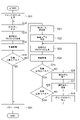
- step S01 the control unit 112 drives the motor 3.
- step S02 the control unit 112 acquires the detected value of the state of the drive target 4 by the sensor 6 and stores it in the response profile storage unit 113 in chronological order.
- step S03 the control unit 112 confirms whether the supply of the drive power based on the command profile is completed over the entire period of the command profile.
- step S03 If it is determined in step S03 that the period in which the drive power supply based on the command profile is not completed remains, the control device 100 returns the process to step S01. After that, the control device 100 supplies the drive power based on the command profile to the motor 3 until the supply of the drive power is completed over the entire period of the command profile, and the sensor 6 detects the state of the drive target 4. And repeat in a predetermined control cycle.
- step S03 the supply of the drive power based on the command profile is completed over the entire period of the command profile, the acquisition of the response profile is completed.
- the control device 100 first executes steps S11, S12, S13, S14, and S15.
- step S11 the first model generation unit 114 generates a gain profile showing the relationship between the command frequency and the response gain of the controlled object 2 to the command based on the command profile and the response profile, and stores the gain profile. It is stored in the unit 115.
- step S12 the first model generation unit 114 generates the first model based on the linear model whose frequency characteristics are fitted to the gain profile.
- step S13 the model evaluation unit 122 sets the control target 2 according to the command profile based on the command profile stored in the command profile storage unit 111 and the first model and the second model stored in the model storage unit 121.
- a virtual response profile simulating the time change of the state is generated and stored in the virtual profile storage unit 123.
- the model evaluation unit 122 generates a virtual response profile based only on the command profile and the first model.
- step S14 the model evaluation unit 122 evaluates the error of the virtual response profile with respect to the response profile based on the response profile stored in the response profile storage unit 113 and the virtual response profile stored in the virtual profile storage unit 123.
- step S15 the second model generation unit 132 confirms whether the error evaluation result in step S14 is equal to or lower than the first level.
- step S15 If it is determined in step S15 that the error evaluation result is not equal to or lower than the first level, the control device 100 executes steps S21, S22, S23, S24, and S25.
- step S21 the second model generation unit 132 temporarily generates the second model based on the weighted sum of the plurality of types of unit models, and stores the second model in the model storage unit 121.
- the second model generation unit 132 generates an error model based on the tentatively generated second model and the error evaluation result based on the tentatively generated second model. For example, the second model generation unit 132 stores a record in which the temporarily generated second model and the evaluation result of the error based on the temporarily generated second model are associated with each other in the learning data storage unit 133. After that, the second model generation unit 132 generates an initial error model based on the record stored in the learning data storage unit 133, and stores the generated initial error model in the error model storage unit 134.
- step S23 the model evaluation unit 122 sets the control target 2 according to the command profile based on the command profile stored in the command profile storage unit 111 and the first model and the second model stored in the model storage unit 121.
- a virtual response profile simulating the time change of the state is generated and stored in the virtual profile storage unit 123.
- step S24 the model evaluation unit 122 evaluates the error of the virtual response profile with respect to the response profile based on the response profile stored in the response profile storage unit 113 and the virtual response profile stored in the virtual profile storage unit 123.
- step S25 the second model generation unit 132 confirms whether the error evaluation result in step S24 is equal to or lower than the second level.
- step S25 If it is determined in step S25 that the error evaluation result is not the second level or less, the control device 100 executes steps S26 and S27.
- step S26 the second model generation unit 132 changes the weight based on the target error of the second level or lower and the error model, and stores the second model after the weight change in the model storage unit 121.
- step S27 the second model generation unit 132 updates the error model based on the second model after the weight change and the error evaluation result based on the second model after the weight change.
- the second model generation unit 132 stores in the learning data storage unit 133 a record in which the second model after the weight change and the error evaluation result based on the second model after the weight change are associated with each other.
- the second model generation unit 132 updates the error model of the error model storage unit 134 based on the records accumulated by the learning data storage unit 133.
- the control device 100 returns the process to step S23. After that, the change of the second model based on the error model and the update of the error model based on the changed second model are repeated until the error evaluation result becomes the second level or less.
- step S25 If it is determined in step S25 that the error evaluation result is the second level or less, the control device 100 executes step S28.
- step S28 the first model generation unit 114 confirms whether the error evaluation result in step S24 is equal to or lower than the first level.
- step S29 the first model generation unit 114 changes the gain profile based on the command profile, the response profile, and the second model. After that, the control device 100 returns the process to step S02. As a result, the first model is regenerated based on the changed gain profile.
- step S15 When it is determined in step S15 that the error evaluation result is the first level or less, and when it is determined in step S28 that the error evaluation result is the first level or less, the control device 100 executes step S31.
- step S31 the parameter generation unit 141 generates the control parameter based on the first model and the second model stored in the model storage unit 121, and stores the control parameter in the parameter storage unit 142. This completes the control parameter generation procedure.
- control procedure a control procedure based on the control parameters will be illustrated.
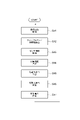
- the control device 100 executes steps S41, S42, S43, S44, S45, S46, and S47 in order.
- step S41 the control unit 112 acquires the target position.
- the control unit 112 may acquire the target position based on the target operation pattern of the drive target 4 given in advance, or may acquire the target position from the upper controller.
- step S42 the control unit 112 calculates the feedforward compensation value based on the target position and the control parameters stored in the parameter storage unit 142.
- step S43 the control unit 112 acquires information on the current position and current speed of the drive target 4 based on the detected value of the sensor 6.
- step S44 the control unit 112 calculates the target speed based on the deviation between the target position and the current position.
- step S45 the control unit 112 calculates a driving force command based on the deviation between the target speed and the current speed.
- step S46 the control unit 112 adds the feedforward compensation value to the driving force command to calculate the corrected command.
- step S47 the control unit 112 generates drive power based on the corrected command and supplies it to the motor 3. The control unit 112 repeats the above procedure in a predetermined control cycle.
- the above-mentioned configuration can be applied to a control target in which a plurality of motors are used and the drive target includes a plurality of rigid bodies.
- the above configuration is also applicable to the articulated robot illustrated in FIG.
- the robot 10 shown in FIG. 6 is a so-called 6-axis vertical articulated robot, and has a base 11, a swivel portion 12, arms 13, 14, 15, and a tool holding portion 16.
- the base 11 is fixed on the floor, the base, or an AGV (Automated Guided Vehicle) in the work area.
- the swivel portion 12 is provided on the base 11 so as to swivel around the vertical axis 31.
- the arm 13 is connected to the swivel portion 12 so as to swing around the axis 32 that intersects (for example, is orthogonal to) the axis 31.
- the intersection here includes a case where there is a twisting relationship such as a so-called grade separation.
- the arm 14 is connected to the tip of the arm 13 so as to swing around the axis 33 parallel to the axis 32.
- the arm 15 is connected to the tip of the arm 14 so as to swing around the axis 34 that intersects the axis 33 along the arm 14 and swings around the axis 35 that intersects (for example, orthogonally) the axis 34.
- the tool holding portion 16 is connected to the tip end portion of the arm 15 so as to rotate around the axis 36 along the center of the arm 15.
- the tool holding portion 16 holds various tools 17 such as a hand for gripping a work, a welding torch, a painting gun, or a screw tightening tool.
- the motor 21 swings the swivel portion 12 around the axis 31, the motor 22 swings the arm 13 around the axis 32, the motor 23 swings the arm 14 around the axis 33, and the motor 24 swings the arm around the axis 33.
- the tip of the arm 14 is swiveled around 34, the motor 25 swings the arm 15 around the axis 35, and the motor 26 swivels the tool holding portion 16 around the axis 36.
- the tool holding unit 16 and the tool 17 are the driving targets of the motor 26.
- the arm 15, the tool holding portion 16, and the tool 17 are the driving targets of the motor 25.
- the tip of the arm 14, the arm 15, the tool holding portion 16 and the tool 17 are the driving targets of the motor 24.
- the arms 14, 15, the tool holding portion 16, and the tool 17 are the driving targets of the motor 23.
- the arms 13, 14, 15, the tool holding portion 16 and the tool 17 are the driving targets of the motor 22.
- the swivel portion 12, the arms 13, 14, 15, the tool holding portion 16 and the tool 17 are the driving targets of the motor 21.
- control device 100 may execute the above-mentioned control parameter generation procedure and the motor control procedure based on the control parameters for each motor.
- the control device 100 responds to the command based on the command profile representing the time change of the command to the control target 2 and the response profile representing the time change of the state of the control target 2 according to the command profile.
- the first model generation unit 114 that generates the first model representing at least a part of the response characteristics of the controlled object 2
- the command profile, the response profile, and the first model the first model of the response characteristics is selected.
- the second model generation unit 132 that generates the second model representing the characteristics that are not included, the first model, and the second model, the command and the control amount for making the control target 2 follow the command. It includes a parameter generation unit 141 that generates control parameters that determine relationships.
- a second model representing the characteristics not included in the first model is further generated based on the first model, and the first model and the second model are combined.
- the simulation is executed based on. In this way, by using the two types of models, the controlled object 2 can be modeled more appropriately. Therefore, it is effective in improving the accuracy of the simulation.
- the second model generation unit 132 may generate a second model based on a plurality of types of unit models prepared in advance. In this case, characteristics that are difficult to model by the first model (for example, non-linear characteristics) can be easily modeled.
- Each of the plurality of types of unit models may be a model representing non-linear characteristics with respect to a command. In this case, it is possible to easily model nonlinear characteristics that cannot be modeled by a linear model.
- the second model generation unit 132 creates an error model that represents the relationship between the weights of a plurality of types of unit models in the second model and the evaluation result of the error, based on the second model that is provisionally generated and the second model that is provisionally generated. It is generated based on the evaluation result of the error, and the weight is changed based on the predetermined target error and the error model, and the second model after the weight is changed and the second model after the weight is changed.
- the second model may be generated by repeating the process of updating the error model based on the evaluation result of the error based on the result until a predetermined condition is satisfied. In this case, characteristics that are difficult to model by the first model can be modeled more quickly.
- the first model generation unit 114 generates a gain profile showing the relationship between the command frequency and the response gain of the controlled object 2 to the command based on the command profile and the response profile, and fits the frequency characteristics to the gain profile.
- the first model may be generated based on the linear model. In this case, since the linear model can be fitted by frequency analysis, easy and appropriate modeling becomes possible.
- the first model generation unit 114 generates the first model based on the command profile, the response profile, and the second model when the evaluation result of the error after the second model is generated exceeds a predetermined level. It may be regenerated. In this case, it is expected that the accuracy of the first model will be further improved by regenerating the first model in consideration of the second model after the second model is generated. Therefore, more appropriate modeling is possible.
- the first model generation unit 114 changes the gain profile based on the command profile, the response profile, and the second model when the error evaluation result after the second model is generated exceeds a predetermined level. Then, the frequency characteristics of the linear model may be fitted to the changed gain profile to regenerate the first model. In this case, by changing the gain profile based on the second model, the reproduction of the first model can be easily and appropriately performed as in the first generation.
- the first model generation unit 114 may use the response profile based on the command profile, the response profile, and the second model.
- a modified profile may be generated with the response of the second model removed, and the gain profile may be modified based on the command profile and the modified profile. In this case, the gain profile can be easily changed.
- the second model generation unit 132 is a second model based on the command profile, the response profile, and the first model when the evaluation result of the error after the first model is regenerated exceeds a predetermined level. May be regenerated. In this case, it is expected that the accuracy of the second model will be further improved by regenerating the second model in consideration of the first model after the first model is regenerated. Therefore, more appropriate modeling is possible.
- the control device 100 generates a virtual response profile that simulates the time change of the state of the controlled object 2 according to the command profile based on the command profile, the first model, and the second model, and generates a virtual response to the response profile.
- the model evaluation unit 122 for evaluating the error of the profile is further provided, and the second model generation unit 132 temporarily generates the second model and modifies the second model based on the evaluation result of the error based on the second model.
- the second model is generated repeatedly until a predetermined condition is satisfied, and the first model generation unit 114 determines that the error evaluation result after the second model is generated exceeds the predetermined first level.
- the first model may be regenerated based on the command profile, the response profile, and the second model.
- the second model generation unit 132 repeatedly changes the second model based on the error evaluation result based on the second model until the error evaluation result becomes higher than the first level and is equal to or lower than the second level.
- a second model may be generated.
- the second model generation unit 132 is based on the command profile, the response profile, and the first model when the evaluation result of the error after the first model is regenerated exceeds the first level.
- the model may be regenerated.
- the control target 2 has a drive target 4 and a motor 3 that drives the drive target 4.
- the command is a command of the driving force generated by the motor 3, and the state of the control target 2 is the speed of the drive target 4. May be.
- the control target 2 has a drive target 4 and a motor 3 that drives the drive target 4.
- the command is a command of the driving force generated by the motor 3, and the state of the control target 2 is the position of the drive target 4. May be.
- the time change of the command in the command profile may include the vibration of the command.
- Control target 3 ... Motor, 4 ... Drive target, 100 ...
- Control device control system production device
- 114 First model generation unit, 122 ... Model evaluation unit, 132 ... Second model generation unit, 141 ... Parameter generator.
Landscapes
- Engineering & Computer Science (AREA)
- Robotics (AREA)
- Mechanical Engineering (AREA)
- Human Computer Interaction (AREA)
- Computer Vision & Pattern Recognition (AREA)
- Artificial Intelligence (AREA)
- Health & Medical Sciences (AREA)
- Evolutionary Computation (AREA)
- Medical Informatics (AREA)
- Software Systems (AREA)
- Physics & Mathematics (AREA)
- General Physics & Mathematics (AREA)
- Automation & Control Theory (AREA)
- Feedback Control In General (AREA)
Priority Applications (3)
| Application Number | Priority Date | Filing Date | Title |
|---|---|---|---|
| JP2022555003A JP7578244B2 (ja) | 2020-10-06 | 2020-10-06 | 制御システムの生産装置、制御システムの生産方法及びプログラム |
| PCT/JP2020/037868 WO2022074734A1 (ja) | 2020-10-06 | 2020-10-06 | 制御システムの生産装置、制御システムの生産方法及びプログラム |
| US18/192,646 US12304077B2 (en) | 2020-10-06 | 2023-03-30 | Modeling of controlled object |
Applications Claiming Priority (1)
| Application Number | Priority Date | Filing Date | Title |
|---|---|---|---|
| PCT/JP2020/037868 WO2022074734A1 (ja) | 2020-10-06 | 2020-10-06 | 制御システムの生産装置、制御システムの生産方法及びプログラム |
Related Child Applications (1)
| Application Number | Title | Priority Date | Filing Date |
|---|---|---|---|
| US18/192,646 Continuation US12304077B2 (en) | 2020-10-06 | 2023-03-30 | Modeling of controlled object |
Publications (1)
| Publication Number | Publication Date |
|---|---|
| WO2022074734A1 true WO2022074734A1 (ja) | 2022-04-14 |
Family
ID=81126716
Family Applications (1)
| Application Number | Title | Priority Date | Filing Date |
|---|---|---|---|
| PCT/JP2020/037868 Ceased WO2022074734A1 (ja) | 2020-10-06 | 2020-10-06 | 制御システムの生産装置、制御システムの生産方法及びプログラム |
Country Status (3)
| Country | Link |
|---|---|
| US (1) | US12304077B2 (https=) |
| JP (1) | JP7578244B2 (https=) |
| WO (1) | WO2022074734A1 (https=) |
Cited By (2)
| Publication number | Priority date | Publication date | Assignee | Title |
|---|---|---|---|---|
| JPWO2024161528A1 (https=) * | 2023-01-31 | 2024-08-08 | ||
| JPWO2024161515A1 (https=) * | 2023-01-31 | 2024-08-08 |
Citations (5)
| Publication number | Priority date | Publication date | Assignee | Title |
|---|---|---|---|---|
| JPH05143108A (ja) * | 1991-11-20 | 1993-06-11 | Hitachi Ltd | プロセスの適応制御方法 |
| JP2004178247A (ja) * | 2002-11-27 | 2004-06-24 | Toyota Motor Corp | モデル作成方法、モデル作成プログラム及びシミュレーション装置 |
| JP2007264796A (ja) * | 2006-03-27 | 2007-10-11 | Hitachi Ltd | プラント制御方法及びプラント制御装置 |
| WO2019159883A1 (ja) * | 2018-02-13 | 2019-08-22 | 三菱日立パワーシステムズ株式会社 | モデル作成方法、プラントの運転支援方法、モデル作成装置、モデル、プログラム、及びプログラムを記録した記録媒体 |
| JP2020030575A (ja) * | 2018-08-22 | 2020-02-27 | 株式会社日立製作所 | プラント操業支援装置 |
Family Cites Families (27)
| Publication number | Priority date | Publication date | Assignee | Title |
|---|---|---|---|---|
| DE68928484T2 (de) * | 1988-03-25 | 1998-07-23 | Hitachi Ltd | Verfahren zum erkennen von bildstrukturen |
| US5268834A (en) * | 1991-06-24 | 1993-12-07 | Massachusetts Institute Of Technology | Stable adaptive neural network controller |
| US5598076A (en) * | 1991-12-09 | 1997-01-28 | Siemens Aktiengesellschaft | Process for optimizing control parameters for a system having an actual behavior depending on the control parameters |
| JP3269852B2 (ja) * | 1992-05-29 | 2002-04-02 | 本田技研工業株式会社 | 脚式移動ロボットの姿勢安定化制御装置 |
| GB9417170D0 (en) * | 1994-08-25 | 1994-10-12 | Isis Innovation | Non-linear filtering |
| US7085688B1 (en) | 1999-10-22 | 2006-08-01 | Shizuo Sumida | Non-linear characteristic reproducing apparatus and non-linear characteristic reproducing program storage medium |
| JP2007149124A (ja) * | 1999-10-22 | 2007-06-14 | Shizuo Tsunoda | 非線形特性再現装置、非線形抵抗再現装置、および非線形特性再現プログラム記憶媒体 |
| JP3887578B2 (ja) * | 2002-03-29 | 2007-02-28 | 株式会社東芝 | プロセス運転計画システム |
| JP2007109103A (ja) * | 2005-10-14 | 2007-04-26 | Toyota Motor Corp | 多入力多出力系の制御装置 |
| US7660639B2 (en) | 2006-03-27 | 2010-02-09 | Hitachi, Ltd. | Control system for control subject having combustion unit and control system for plant having boiler |
| WO2009123650A1 (en) * | 2008-04-02 | 2009-10-08 | Irobot Corporation | Robotics systems |
| WO2014028557A1 (en) * | 2012-08-15 | 2014-02-20 | Intuitive Surgical Operations, Inc. | Phantom degrees of freedom for manipulating the movement of mechanical bodies |
| US9440353B1 (en) * | 2014-12-29 | 2016-09-13 | Google Inc. | Offline determination of robot behavior |
| US9545995B1 (en) * | 2015-07-14 | 2017-01-17 | Qualcomm Incorporated | Control normalization for unmanned autonomous systems |
| JP6998660B2 (ja) | 2017-02-21 | 2022-01-18 | 株式会社安川電機 | ロボットシミュレータ、ロボットシステム及びシミュレーション方法 |
| US11148288B2 (en) * | 2017-02-25 | 2021-10-19 | Diligent Robotics, Inc. | Systems, apparatus, and methods for robotic learning and execution of skills |
| US10773382B2 (en) * | 2017-09-15 | 2020-09-15 | X Development Llc | Machine learning methods and apparatus for robotic manipulation and that utilize multi-task domain adaptation |
| US10792810B1 (en) * | 2017-12-14 | 2020-10-06 | Amazon Technologies, Inc. | Artificial intelligence system for learning robotic control policies |
| JP6873941B2 (ja) * | 2018-03-02 | 2021-05-19 | 株式会社日立製作所 | ロボット作業システム、及びロボット作業システムの制御方法 |
| EP3566824B1 (en) * | 2018-05-11 | 2023-06-28 | Siemens Aktiengesellschaft | Method, apparatus, computer-readable storage media and a computer program for robotic programming |
| EP3566823A1 (en) * | 2018-05-11 | 2019-11-13 | Siemens Aktiengesellschaft | Method, apparatus and system for robotic programming |
| US11325252B2 (en) * | 2018-09-15 | 2022-05-10 | X Development Llc | Action prediction networks for robotic grasping |
| JP6508691B1 (ja) * | 2018-10-15 | 2019-05-08 | 株式会社Mujin | 制御装置、作業ロボット、プログラム、及び、制御方法 |
| US11461589B1 (en) * | 2019-02-04 | 2022-10-04 | X Development Llc | Mitigating reality gap through modification of simulated state data of robotic simulator |
| JP7200037B2 (ja) * | 2019-04-17 | 2023-01-06 | 株式会社日立製作所 | 機械の自動運転制御方法、及びシステム |
| JP7326911B2 (ja) * | 2019-06-20 | 2023-08-16 | オムロン株式会社 | 制御システムおよび制御方法 |
| US11213953B2 (en) * | 2019-07-26 | 2022-01-04 | Google Llc | Efficient robot control based on inputs from remote client devices |
-
2020
- 2020-10-06 WO PCT/JP2020/037868 patent/WO2022074734A1/ja not_active Ceased
- 2020-10-06 JP JP2022555003A patent/JP7578244B2/ja active Active
-
2023
- 2023-03-30 US US18/192,646 patent/US12304077B2/en active Active
Patent Citations (5)
| Publication number | Priority date | Publication date | Assignee | Title |
|---|---|---|---|---|
| JPH05143108A (ja) * | 1991-11-20 | 1993-06-11 | Hitachi Ltd | プロセスの適応制御方法 |
| JP2004178247A (ja) * | 2002-11-27 | 2004-06-24 | Toyota Motor Corp | モデル作成方法、モデル作成プログラム及びシミュレーション装置 |
| JP2007264796A (ja) * | 2006-03-27 | 2007-10-11 | Hitachi Ltd | プラント制御方法及びプラント制御装置 |
| WO2019159883A1 (ja) * | 2018-02-13 | 2019-08-22 | 三菱日立パワーシステムズ株式会社 | モデル作成方法、プラントの運転支援方法、モデル作成装置、モデル、プログラム、及びプログラムを記録した記録媒体 |
| JP2020030575A (ja) * | 2018-08-22 | 2020-02-27 | 株式会社日立製作所 | プラント操業支援装置 |
Cited By (4)
| Publication number | Priority date | Publication date | Assignee | Title |
|---|---|---|---|---|
| JPWO2024161528A1 (https=) * | 2023-01-31 | 2024-08-08 | ||
| JPWO2024161515A1 (https=) * | 2023-01-31 | 2024-08-08 | ||
| JP7771439B2 (ja) | 2023-01-31 | 2025-11-17 | Ntt株式会社 | 無線通信システム、無線通信装置、無線通信方法及び信号補償プログラム |
| JP7787337B2 (ja) | 2023-01-31 | 2025-12-16 | Ntt株式会社 | 無線通信システム、無線通信装置、無線通信方法及び信号補償プログラム |
Also Published As
| Publication number | Publication date |
|---|---|
| JPWO2022074734A1 (https=) | 2022-04-14 |
| US20230234223A1 (en) | 2023-07-27 |
| US12304077B2 (en) | 2025-05-20 |
| JP7578244B2 (ja) | 2024-11-06 |
Similar Documents
| Publication | Publication Date | Title |
|---|---|---|
| JP7199178B2 (ja) | ロボット制御装置、ロボット装置、ロボット制御のパラメータ調整方法、およびプログラム | |
| JP6669715B2 (ja) | 振動抑制装置 | |
| CN104283484B (zh) | 具备前馈控制的电动机控制装置 | |
| EP2752274B1 (en) | Control method and control device | |
| CN102904521B (zh) | 具有同时推定惯量、摩擦和弹性的功能的电动机控制装置 | |
| JP5932578B2 (ja) | 振動抑制方法、振動抑制装置および振動抑制機能を備えた産業用機械装置 | |
| Qazani et al. | High-fidelity hexarot simulation-based motion platform using fuzzy incremental controller and model predictive control-based motion cueing algorithm | |
| JP2018118353A (ja) | 学習制御機能を備えた制御システム及び制御方法 | |
| JP5916583B2 (ja) | 多関節ロボットのウィービング制御装置 | |
| US12304077B2 (en) | Modeling of controlled object | |
| JP6386516B2 (ja) | 学習機能を備えたロボット装置 | |
| JP7548036B2 (ja) | 動作パラメーター調整方法、動作パラメーター調整プログラムおよびロボットシステム | |
| JP2005316937A (ja) | 制御装置およびその制御方法 | |
| CN113924192A (zh) | 用于估计机器人操作参数的方法和计算系统 | |
| JP2013004037A (ja) | 振動抑制方法 | |
| Driessen et al. | Experimental demonstration of high-performance robotic balancing | |
| JP2016032326A (ja) | モータ制御装置、ロボット装置、モータ制御方法、プログラム及び記録媒体 | |
| CN109129475A (zh) | 机械臂的重力补偿方法、装置、系统及存储介质 | |
| CN109507879B (zh) | 控制装置以及机器学习装置 | |
| JP7222427B2 (ja) | 制御システム、制御装置及び制御方法 | |
| JP5283804B1 (ja) | サーボ制御装置 | |
| JP4105492B2 (ja) | 負荷試験システムおよび負荷試験方法 | |
| CN114800523B (zh) | 机械臂轨迹修正方法、系统、计算机及可读存储介质 | |
| Aksman et al. | Force estimation based compliance control of harmonically driven manipulators | |
| JPWO2022074734A5 (https=) |
Legal Events
| Date | Code | Title | Description |
|---|---|---|---|
| 121 | Ep: the epo has been informed by wipo that ep was designated in this application |
Ref document number: 20956683 Country of ref document: EP Kind code of ref document: A1 |
|
| ENP | Entry into the national phase |
Ref document number: 2022555003 Country of ref document: JP Kind code of ref document: A |
|
| NENP | Non-entry into the national phase |
Ref country code: DE |
|
| 122 | Ep: pct application non-entry in european phase |
Ref document number: 20956683 Country of ref document: EP Kind code of ref document: A1 |