WO2022071067A1 - 摺動機構、圧縮機、摺動機構の製造方法及び圧縮機の製造方法 - Google Patents
摺動機構、圧縮機、摺動機構の製造方法及び圧縮機の製造方法 Download PDFInfo
- Publication number
- WO2022071067A1 WO2022071067A1 PCT/JP2021/034837 JP2021034837W WO2022071067A1 WO 2022071067 A1 WO2022071067 A1 WO 2022071067A1 JP 2021034837 W JP2021034837 W JP 2021034837W WO 2022071067 A1 WO2022071067 A1 WO 2022071067A1
- Authority
- WO
- WIPO (PCT)
- Prior art keywords
- sliding
- wire
- sliding member
- microtexture
- groove
- Prior art date
- Legal status (The legal status is an assumption and is not a legal conclusion. Google has not performed a legal analysis and makes no representation as to the accuracy of the status listed.)
- Ceased
Links
Images



Classifications
-
- B—PERFORMING OPERATIONS; TRANSPORTING
- B23—MACHINE TOOLS; METAL-WORKING NOT OTHERWISE PROVIDED FOR
- B23H—WORKING OF METAL BY THE ACTION OF A HIGH CONCENTRATION OF ELECTRIC CURRENT ON A WORKPIECE USING AN ELECTRODE WHICH TAKES THE PLACE OF A TOOL; SUCH WORKING COMBINED WITH OTHER FORMS OF WORKING OF METAL
- B23H7/00—Processes or apparatus applicable to both electrical discharge machining and electrochemical machining
- B23H7/02—Wire-cutting
-
- F—MECHANICAL ENGINEERING; LIGHTING; HEATING; WEAPONS; BLASTING
- F04—POSITIVE - DISPLACEMENT MACHINES FOR LIQUIDS; PUMPS FOR LIQUIDS OR ELASTIC FLUIDS
- F04C—ROTARY-PISTON, OR OSCILLATING-PISTON, POSITIVE-DISPLACEMENT MACHINES FOR LIQUIDS; ROTARY-PISTON, OR OSCILLATING-PISTON, POSITIVE-DISPLACEMENT PUMPS
- F04C18/00—Rotary-piston pumps specially adapted for elastic fluids
- F04C18/30—Rotary-piston pumps specially adapted for elastic fluids having the characteristics covered by two or more of groups F04C18/02, F04C18/08, F04C18/22, F04C18/24, F04C18/48, or having the characteristics covered by one of these groups together with some other type of movement between co-operating members
- F04C18/34—Rotary-piston pumps specially adapted for elastic fluids having the characteristics covered by two or more of groups F04C18/02, F04C18/08, F04C18/22, F04C18/24, F04C18/48, or having the characteristics covered by one of these groups together with some other type of movement between co-operating members having the movement defined in group F04C18/08 or F04C18/22 and relative reciprocation between the co-operating members
- F04C18/356—Rotary-piston pumps specially adapted for elastic fluids having the characteristics covered by two or more of groups F04C18/02, F04C18/08, F04C18/22, F04C18/24, F04C18/48, or having the characteristics covered by one of these groups together with some other type of movement between co-operating members having the movement defined in group F04C18/08 or F04C18/22 and relative reciprocation between the co-operating members with vanes reciprocating with respect to the outer member
-
- F—MECHANICAL ENGINEERING; LIGHTING; HEATING; WEAPONS; BLASTING
- F04—POSITIVE - DISPLACEMENT MACHINES FOR LIQUIDS; PUMPS FOR LIQUIDS OR ELASTIC FLUIDS
- F04C—ROTARY-PISTON, OR OSCILLATING-PISTON, POSITIVE-DISPLACEMENT MACHINES FOR LIQUIDS; ROTARY-PISTON, OR OSCILLATING-PISTON, POSITIVE-DISPLACEMENT PUMPS
- F04C29/00—Component parts, details or accessories of pumps or pumping installations, not provided for in groups F04C18/00 - F04C28/00
Definitions
- the present disclosure relates to a sliding mechanism, a compressor, a method for manufacturing the sliding mechanism, and a method for manufacturing the compressor.
- the blade guide groove (hereinafter referred to as “sliding member accommodating portion") and the blade (hereinafter referred to as “sliding member”) are covered with lubricating oil such as dents and grooves by masking and shot blasting.
- lubricating oil such as dents and grooves by masking and shot blasting.
- Patent Document 1 does not describe how a lubricating oil holding portion (hereinafter referred to as “groove portion”) is formed on the sliding surface of the sliding member accommodating portion by masking and shot blasting. Since the sliding member accommodating portion is a closed and narrow space, there is a problem that tools and devices cannot be inserted into the sliding member accommodating portion by these methods. Therefore, it is difficult to form a groove for holding the lubricating oil in the sliding member accommodating portion, and the sliding mechanism described in Patent Document 1 has a problem that the lubricating oil cannot be sufficiently held in the sliding member accommodating portion. there were.
- the present disclosure has been made in order to solve the above-mentioned problems, and is a sliding mechanism, a compressor, a method for manufacturing a sliding mechanism, and a method for manufacturing a compressor that can hold lubricating oil in a sliding member accommodating portion.
- the purpose is to provide.
- the sliding mechanism includes a sliding member accommodating portion having a pair of facing sliding surfaces and a sliding member accommodating portion. It is provided with a sliding member slidably arranged between a pair of sliding surfaces via a lubricating oil. At least one of the pair of sliding surfaces of the sliding member accommodating portion extends in a direction intersecting the sliding direction of the sliding member and has a groove portion in which a discharge mark is formed.
- the compressor according to the present disclosure is arranged in a cylindrical and hollow cylinder having a cylinder chamber, a suction hole for sucking the refrigerant, and a discharge hole for discharging the compressed refrigerant, and a cylinder chamber.
- the cylinder is provided with a piston that sucks the refrigerant into the cylinder chamber with the eccentric rotation and discharges the compressed refrigerant, and the cylinder has the sliding mechanism described in the present disclosure.
- the method for manufacturing a sliding mechanism includes a step of installing a process to be machined having a sliding member accommodating portion having a pair of sliding surfaces in a wire electric discharge machine, and a pair of sliding member accommodating portions.
- a pair of sliding surfaces by the process of stretching a wire on a wire electric discharge machine in a direction parallel to the sliding surface and intersecting the sliding direction of the sliding member, and by discharging the wire and discharging the wire. It has a step of forming a groove on at least one of the above.
- the method for manufacturing a compressor according to the present disclosure includes a step of installing a cylindrical and hollow cylinder having a sliding member accommodating portion having a pair of sliding surfaces in a wire electric discharge machine, and a sliding member. By the process of stretching the wire on the wire electric discharge machine in the direction parallel to the pair of sliding surfaces of the accommodating portion and intersecting the sliding direction of the sliding member, and by discharging the wire and discharging the wire. , A step of forming a groove on at least one of a pair of sliding surfaces.
- the lubricating oil can be held in the sliding member accommodating portion.
- FIG. 5 is a cross-sectional view showing a microtexture of the sliding mechanism according to the first embodiment.
- FIG. 3 is a detailed view of a main part showing a wire feeding mechanism of the wire electric discharge machine according to the fifth embodiment.
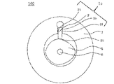
- FIG. 1 is a schematic plan view showing a part of the compressor 100 according to the first embodiment.
- the compressor 100 (described later) includes a piston 5, a spindle 6, and a cylindrical and hollow cylinder 7, which has a sliding mechanism 1a.
- the sliding mechanism 1a includes a sliding member 2 having a sliding surface 21 and a sliding member accommodating portion 3a having a pair of sliding surfaces 31 facing each other.
- the sliding member accommodating portion 3a is formed as a cavity from the inner diameter side to the outer diameter side of the cylinder 7. That is, the sliding member accommodating portion 3a is formed by communicating with the hollow inside of the cylinder 7.
- FIG. 1 is a schematic plan view showing a part of the compressor 100 according to the first embodiment.
- the compressor 100 includes a piston 5, a spindle 6, and a cylindrical and hollow cylinder 7, which has a sliding mechanism 1a.
- the sliding mechanism 1a includes a sliding member 2 having a sliding surface 21 and a sliding member accommodating portion 3a having a pair of sliding surfaces 31 facing each other.
- the sliding member accommodating portion 3 has a sliding surface 31 on the inner diameter side of the cylinder 7, and the outer diameter side of the cylinder 7 is circular.
- One end of the sliding member 2 is arranged between a pair of sliding surfaces 31 facing each other of the sliding member accommodating portion 3a, and the other end is in contact with the peripheral wall of the piston 5.
- the portion where the sliding member 2 and the piston 5 are in contact with each other is referred to as a contact portion 51.
- Lubricating oil (not shown in FIG. 1) is filled between the sliding member 2 and the sliding member accommodating portion 3a. Further, although not shown in FIG.
- a microtexture 4a that is, a groove portion, which is a concave groove for holding the lubricating oil, is formed on the sliding surface 31 of the sliding member accommodating portion 3a.
- the piston 5 rotates around the spindle 6.
- the sliding member 2 is driven by the eccentric rotation of the piston 5 via the contact portion 51 with the piston 5, and slides in the sliding member accommodating portion 3a in the radial direction of the cylindrical cylinder 7.
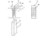
- FIG. 2 is an exploded schematic view showing the sliding mechanism 1a according to the first embodiment.
- FIG. 2A is a schematic perspective view of the sliding mechanism 1a
- FIG. 2B is a schematic front view of the sliding member accommodating portion 3a.
- the sliding member accommodating portion 3a has a sliding surface 21 facing the sliding surface 21 of the sliding member 2 via a lubricating oil.
- a microtexture 4a is formed on the sliding surface 31.
- the microtexture 4a extends in a direction intersecting the sliding direction of the sliding member 2. In FIG. 2, the direction in which the microtexture 4a extends is orthogonal to the sliding direction of the sliding member 2.
- the microtexture 4a has a fluid dynamic pressure effect of generating a positive pressure on the fluid film of the lubricating oil to levitate the sliding surface 21. Further, the microtexture 4a has a fluid holding effect in which the lubricating oil is held in the concave groove.
- the microtexture 4a has an effect of collecting wear debris that suppresses the biting of the wear debris by collecting the wear debris generated in the process of sliding the sliding member 2 in the concave groove. Further, the microtexture 4a has an effect of suppressing solid contact and adhesive wear of the sliding member 2 and the sliding member accommodating portion 3a by holding the lubricating oil. By combining the above effects, the microtexture 4a is formed on the sliding surface 31 of the sliding member accommodating portion 3a, which leads to the improvement of the friction resistance property of the sliding mechanism 1a.
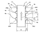
- FIG. 3 is a schematic top view showing the operation of the sliding mechanism 1a according to the first embodiment.
- a lubricating oil (not shown in FIG. 3) is interposed between the sliding member 2 and the sliding member accommodating portion 3a.
- the sliding member 2 also slides in the direction opposite to the arrow AR1. At this time, the direction in which the lubricating oil flows is opposite to the arrow AR2 in FIG. 3, but the point where a force is applied to the sliding member 2 in the direction away from the sliding member accommodating portion 3a is that the sliding member 2 Is the same as the case where is slid in the direction of the arrow AR1.
- the number of microtextures 4a formed in the sliding member accommodating portion 3a may be one on one sliding surface 31, but as shown in FIG. 2, a plurality of microtextures 4a may be formed on one sliding surface 31. good.
- the spacing dimension p of each microtexture 4a may be arbitrarily set so as to be effective for retaining the oil film by the lubricating oil.
- the width and depth of one microtexture 4a (hereinafter referred to as "groove width and groove depth", respectively) are, for example, a groove width dimension w of 10 to 60 ⁇ m and a groove depth dimension d of 2 to 10 ⁇ m. And it is sufficient.
- the dimension of the interval dimension p of the microtexture 4a may be, for example, 100 to 500 ⁇ m.
- the wire electric discharge machine that forms the microtexture 4a is originally used for cutting an object to be machined.
- a wire electric discharge machine is used to form a microtexture 4a. Therefore, the conditions of use of the wire electric discharge machine in the present disclosure are different from the conditions of cutting of the wire electric discharge machine normally used.
- the gap dimension W of the sliding member accommodating portion 3a, that is, the distance between the sliding surfaces 31 is, for example, 10 mm or less.
- the microtexture 4a When the microtexture 4a is formed on the sliding surface 31 of the sliding member accommodating portion 3a, a laser machine or the like is installed from the inside of the sliding member accommodating portion 3a, that is, between the sliding surface 31 and the sliding surface 31. It needs to be arranged to form the microtexture 4a. However, the gap of the sliding member accommodating portion 3a is narrow, and even if an attempt is made to form a microtexture 4a on one of the sliding surfaces 31, a processing machine such as a machining center, laser processing, or a forming method such as photoetching may be used. The microtexture 4a cannot be formed because tools and devices cannot be inserted.
- the wire 8 of the wire electric discharge machine is passed through a narrow gap of the sliding member accommodating portion 3a, and the sliding surface 31 of the sliding member accommodating portion 3a is microtextured by electric discharge. 4a can be formed. Therefore, if the wire 8 can be passed through, the microtexture 4a can be formed even in a narrow gap where a laser beam machine or the like cannot be arranged.
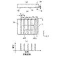
- FIG. 4 is a diagram illustrating a method of forming a microtexture 4a by a wire electric discharge machine.
- FIG. 4A is a top view showing the positional relationship between the wire 8 of the wire electric discharge machine and the object to be machined, for example, the sliding member accommodating portion 3a of the cylinder 7, and
- FIG. 4B is a sliding surface view. It is a side view which shows the positional relationship with the moving member accommodating part 3.
- the sliding direction of the sliding member 2 is the X direction (arrow AR1 direction)
- the extending direction of the microtexture 4a is the Y direction. That is, the Y direction in FIG. 4B is a direction orthogonal to the sliding direction of the sliding member 2.
- FIG. 4A corresponds to the position of the microtexture 4a in FIG. 4B.
- the arrow AR3 shown in FIG. 4 indicates the scanning direction of the wire 8.
- FIG. 4C is a diagram showing an application state of a discharge pulse of a wire electric discharge machine, with the horizontal axis representing time and travel distance and the vertical axis representing voltage.
- the horizontal axis of FIG. 4C corresponds to the dimension in the X direction of FIG. 4B, and corresponds to the position of the wire 8 of the wire electric discharge machine when a pulse is applied.
- a method of forming a microtexture 4a using a wire electric discharge machine to manufacture a sliding mechanism 1 will be described. First, a sliding member accommodating portion 3a of the object to be machined is installed in a wire electric discharge machine (not shown in FIG. 4). Next, the wire 8 is stretched on the wire electric discharge machine. The positional relationship between the sliding member accommodating portion 3a and the wire 8 is set to a predetermined position, and an electric discharge is generated.
- the wire 8 of the wire discharge processing machine extends in a direction parallel to the sliding member accommodating portion 3a and intersecting the scanning direction of the wire 8, that is, the sliding direction of the sliding member 2. It is arranged and moved in the arrow AR3 direction (X direction) at a constant speed.
- a power source (not shown in FIG. 4) causes an electric discharge at a constant frequency to process the sliding surface 31 of the sliding member accommodating portion 3a. That is, the microtexture 4a is formed in the sliding member accommodating portion 3a.
- the movement of the wire 8 in the X direction may be stopped or the movement speed may be changed at the time of discharging.
- the microtexture 4a which is a concave groove, is formed.
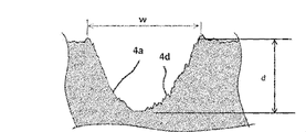
- FIG. 5 is a cross-sectional view showing a microtexture 4a of the sliding mechanism 1 according to the first embodiment.
- FIG. 5 is a diagram showing a cross section (hereinafter, referred to as “groove cross section”) of the sliding member accommodating portion 3a in a direction orthogonal to the extending direction of the wire 8 of the wire electric discharge machine.
- the groove cross section of the microtexture 4 has a shape close to a parabola.
- the groove width dimension w is, for example, 30 to 60 ⁇ m
- the groove depth dimension d is, for example, 2 to 10 ⁇ m.
- the serrated discharge marks 4d (described later) shown on the microtexture 4a are generally found on a machined surface machined by electric discharge machining.
- FIG. 5 shows the microtexture 4a formed when the discharge setting time is 2 seconds. The longer the processing time, the smaller the size of the discharge mark 4d and the smaller the quantity, and the shape of the groove cross section. Tends to be smooth. Therefore, when forming the microtexture 4a, the optimum discharge time may be set from the allowable roughness of the groove cross section and the production time.
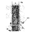
- FIG. 6 is a micrograph showing the microtexture 4a of the sliding mechanism 1 according to the first embodiment.
- FIG. 6 is a micrograph of the microtexture 4a observed from the wire 8 side.
- the sliding member 2 slides in the direction of arrow AR1.
- the discharge setting time at the time of forming the microtexture 4a in FIG. 6 is 5 seconds.
- the discharge time may be lengthened within an allowable range of the processing time.
- the machined surface is affected by heat, and the entire groove, that is, the surface of the concave groove of the microtexture 4a is an altered layer peculiar to electric discharge machining (Fig. 5) is formed.
- the altered layer has a metallic structure such as pearlite or cementite as a layer different from the others.
- a white layer or fine pores can be seen in the altered layer. Similar alteration layers peculiar to electric discharge machining can be seen in other materials.
- the discharge mark 4d shown in FIG. 5 can also be seen on the machined surface.
- the discharge mark 4d is a mark hit by a discharge, and is a surface where the machined surface is once melted and re-solidified, and is serrated and has a rough surface.
- the altered layer and the discharge mark 4d can be observed with a scanning electron microscope or the like, and can be said to be a feature of the processed surface of the microtexture 4a in the present disclosure. Since the discharge mark 4d is fine, it may not be observed in the microtexture 4a.
- the sliding mechanism 1 is slidably arranged between the sliding member accommodating portion 3a having the pair of sliding surfaces 31 facing each other and the pair of sliding surfaces 31 via the lubricating oil.
- a microtexture 4a extending in a direction intersecting the sliding direction of the sliding member 2 is provided on at least one of the pair of sliding surfaces 31 of the sliding member accommodating portion 3a. It has.
- the sliding mechanism 1a can form the microtexture 4a in the sliding member accommodating portion 3a having the pair of sliding surfaces 31 facing each other, so that the sliding member accommodating the sliding member 1a.
- Lubricating oil can be held in the portion 3a.
- the gap dimension W0 of the sliding member accommodating portion 3a is, for example, 10 mm or less as described above, and cannot be machined by a machining center, laser machining, photo etching, or the like. Even if it is narrow, the microtexture 4a can be easily machined on the sliding surface 31 of the sliding member accommodating portion 3a.
- the microtexture 4a is formed on the sliding surface 31 of the sliding member accommodating portion 3a in a state where the wire 8 and the sliding member accommodating portion 3 are not in contact with each other while maintaining a constant distance of 1 ⁇ m. Can be formed. Therefore, the groove width and groove depth of the microtexture 4a can be designed and formed with high accuracy in units of 1 ⁇ m.
- the sliding mechanism 1a is machined by a wire electric discharge machine, there is no need to worry about wear replacement of machining tools such as machining centers. Therefore, the processing cost can be reduced.
- the sliding mechanism 1a is machined by a wire electric discharge machine, it is not necessary to prepare shape specifications such as groove width dimension or pitch dimension of the microtexture 4a with a mold or a film. Further, if necessary, the groove width dimension and the pitch dimension of the microtexture 4a can be individually changed, so that a more optimum microtexture 4a can be obtained.
- the sliding mechanism 1a is machined by a wire electric discharge machine, the machined surface of the microtexture 4a becomes rough due to electric discharge marks, and more lubricating oil can be retained.
- the sliding mechanism 1a is machined by a wire electric discharge machine, unlike machining with a machining tool such as a machining center, no machining force is applied due to non-contact machining, and the sliding member accommodating portion 3a is a hard and brittle material. Even so, defects such as cracks are less likely to occur during machining, and the occurrence of defects can be suppressed.
- the sliding mechanism 1a can suppress the loss due to the sliding of the sliding member 2, the life of the sliding member 2 and the sliding member accommodating portion 3a can be extended.
- the sliding member accommodating portion 3a has a microtexture 4a, it is possible to improve the friction resistance property with the sliding member 2 facing the sliding member 2 via the lubricating oil, and the sliding resistance is increased. Can be suppressed.
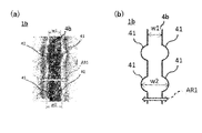
- FIG. 7 is a diagram showing a microtexture 4b of the sliding mechanism 1b according to the second embodiment.
- the sliding member 2 slides in the direction of arrow AR1.
- FIG. 7A is a micrograph of the microtexture 4b observed from the wire 8 side.
- FIG. 7 (b) is a diagram schematically showing FIG. 7 (a).
- the discharge setting time at the time of forming the microtexture 4b in FIG. 7 is 1 second.
- the groove width of the microtexture 4b can be made non-uniform, and the groove width can be made in one microtexture 4b. It is possible to obtain a portion having a groove width dimension w1 having a narrow dimension and a portion having a groove width dimension w2 having a wide groove width dimension.
- the portion of the groove width dimension w2 acts as an oil sump portion 41 in which the lubricating oil is collected, and the friction resistance property can be improved. .. That is, by shortening the discharge setting time, it is possible to intentionally make the groove width non-uniform and form the oil sump portion 41 having a wide groove width.
- the oil pool portion 41 refers to a portion of the microtexture 4b that is recessed in the sliding direction of the sliding member 2.
- the microtexture 4b has an oil sump portion 41 recessed in a direction intersecting the direction in which the microtexture 4b extends.
- the sliding mechanism 1b can form the microtexture 4b in the sliding member accommodating portion 3a having the pair of opposed sliding surfaces 31, and thus accommodates the sliding member.
- Lubricating oil can be held in the portion 3b.
- more lubricating oil can be held in the microtexture 4b by the oil sump portion 41, so that the friction resistance property of the sliding mechanism 1b is improved. Can be improved.
- the discharge setting time can be shortened as compared with the first embodiment, and since it is not necessary to process the oil sump portion 41 in a separate process, the processing time of the microtexture 4b can be shortened. Productivity can be improved.
- the inventors have found that the groove width and the groove depth of the microtexture 4b react sensitively to the discharge time and change almost in proportion to the discharge time. Furthermore, the inventors have confirmed that the groove width of the microtexture 4b is approximately proportional to the wire diameter of the wire 8 and is about half of the wire diameter. From these, the control of the groove width and the groove depth of the microtexture 4b can be realized by the wire electric discharge machine having a wire 8 replacement function and a discharge time control function.
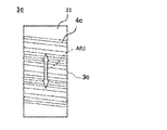
- FIG. 8 is a schematic view showing the microtexture 4c of the sliding mechanism 1c according to the third embodiment.
- the microtextures 4a and 4b extend in a direction orthogonal to the arrow AR1 direction, which is the sliding direction of the sliding member 2. That is, in the first and second embodiments, the angle in the extending direction of the microtextures 4a and 4b, that is, the angle in the extending direction of the wire 8 of the wire electric discharge machine is the arrow AR1 which is the sliding direction of the sliding member 2. It is 90 ° with respect to.
- the angle of the microtexture 4c in the extending direction is formed so as to be inclined at an angle other than 90 ° with respect to the arrow AR1 which is the sliding direction of the sliding member 2.
- the microtexture 4b can be formed at arbitrary intervals that are not constant by arbitrarily setting the frequency of the power supply during processing, and the micro is micro on the sliding surface 31 of the sliding member accommodating portion 3c. It forms the texture 4c.
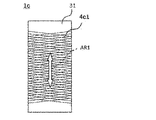
- FIG. 9 is a schematic view showing the microtexture 4c1 of the sliding mechanism 1c according to the third embodiment. As shown in FIG. 9, a plurality of microtextures 4c1 extending at different angles with respect to the sliding direction of the sliding member 2 may be formed on the sliding surface 31 of the sliding member accommodating portion 3.
- the sliding mechanism 1c can form the microtexture 4c or 4c1 on the sliding member accommodating portion 3c having the pair of sliding surfaces 31 facing each other, so that the sliding mechanism 1c slides.
- Lubricating oil can be held in the member accommodating portion 3c.
- the lubricating oil is brought along with the sliding.
- the movement and circulation of the oil film can be easily promoted, and an oil film having better friction characteristics can be formed.
- the angle with respect to the arrow AR1 which is the sliding direction of the sliding member 2 of each microtexture 4c and the interval between the microtextures 4c can be arbitrarily set. Therefore, the optimum microtexture 4c for forming an oil film can be obtained.
- the sliding mechanism 1c can more hold the lubricating oil in the sliding member accommodating portion 3c.
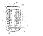
- FIG. 10 is a vertical sectional view showing the compressor 100 according to the fourth embodiment.
- the compressor 100 is classified as a rotary type.
- FIG. 11 is an enlarged plan view showing the compression mechanism unit 50 of the compressor 100 according to the fourth embodiment.
- FIG. 12 is an enlarged view of a main part showing the compression mechanism part 50 according to the fourth embodiment.
- the compressor 100 houses the motor unit 40 and the compression mechanism unit 50 in the closed container 110.
- the motor unit 40 and the compression mechanism unit 50 are connected via a spindle 6.
- Lubricating oil (not shown) is stored in the bottom of the closed container 110.
- the compression mechanism unit 50 includes a cylinder 7, an upper bearing 9, a lower bearing 10, a spindle 6, and a piston 5.
- the cylindrical and hollow cylinder 7 has a cylinder chamber 70 which is a circular space.
- the cylinder chamber 70 is provided with a vane groove 30 as a sliding member accommodating portion that communicates with the cylinder chamber 70 and extends in the radial direction so as to penetrate in the axial direction of the cylinder.
- a vane 20 as a sliding member is slidably arranged in the vane groove 30.
- the vane groove 30 is provided with a back pressure chamber 7d for guiding the discharge pressure and the lubricating oil to the base of the vane groove 30.
- the end on the inner diameter side of the cylinder 7 is pressed against the piston 5 by the spring 11 provided in the back pressure chamber 7d and in contact with the end on the outer diameter side of the cylinder 7.
- the cylinder 7 is provided with a suction hole 7b through which the suction refrigerant from the suction pipe 12 provided in the compressor 100 passes through from the outer peripheral surface of the cylinder 7 to the cylinder chamber 70, and the suction hole 7b is provided. The refrigerant is sucked into the suction space 7e through the suction space 7e.
- a discharge hole 7c is provided which communicates with the discharge space 7f provided on the inner circumference of the cylinder 7 and cuts out the inner peripheral surface of the cylinder 7. The discharge hole 7c leads to the discharge pipe 13.
- the compression mechanism portion 50 has a vane 20 as a sliding member and a vane groove 30 as a sliding member accommodating portion, and the vane groove 30 has a microtexture 4. It is formed.
- the vane groove 30 has a sliding surface 31 on the inner diameter side of the cylinder 7, and the outer diameter side of the cylinder 7 is circular.
- the microtexture 4 refers to at least one of the microtextures 4a, 4b, and 4c described in the first to third embodiments.
- the operation of the compressor 100 will be described.
- the piston 5 is driven via the spindle 6.
- the refrigerant is sucked into the cylinder chamber 70 with the eccentric rotation of the piston 5, the refrigerant is compressed and discharged.
- the vane 20 functions as a partition wall separating the suction space 7e and the discharge space 7f in the cylinder chamber 70 in a state of being arranged inside the vane groove 30.
- the vane 20 slides in the vane groove 30 with the eccentric rotation of the piston 5 in a state where the inner peripheral side of the cylinder 7 is in contact with the peripheral wall of the piston 5.
- the microtexture 4 is formed on the inner wall of the vane groove 30 as the sliding member accommodating portion 3, that is, the sliding surface 31. This makes it possible to reduce the sliding resistance between the outer wall of the vane 20, that is, the sliding surface 21, and the inner wall of the vane groove 30, that is, the sliding surface 31 when the vane 20 slides in the vane groove 30.
- the compressor 100 includes a cylindrical and hollow cylinder 7 having a cylinder chamber 70, a suction hole 7b for sucking the refrigerant, and a discharge hole 7c for discharging the compressed refrigerant.
- the sliding mechanism 1 refers to at least one of the sliding mechanisms 1a, 1b, and 1c described in the first to third embodiments.
- the method for manufacturing the compressor 100 includes a step of installing a cylindrical and hollow cylinder 7 having a vane groove 30 having a pair of sliding surfaces 31 in a wire electric discharge machine, and a vane groove 30.
- the wire 8 is discharged and the discharged wire 8 is used. It has a step of forming a microtexture 4 on at least one of a pair of sliding surfaces 31.
- the vane groove 30 on which the microtexture 4 is formed and the vane facing each other via the lubricating oil have the same effect as those described in the first to third embodiments.
- the friction resistance of 20 can be improved, and an increase in sliding resistance can be suppressed.
- the loss due to the sliding of the sliding mechanism 1 can be suppressed, and the life of the vane 20, the vane groove 30, and the compressor 100 can be extended.
- the vane 20 that partitions the cylinder chamber 70 is heavily loaded with the high-pressure gas, and the sliding loss is large.
- the vane 20 since the microtexture 4 is formed on the vane groove 30 side by the wire electric discharge machine, the vane 20 is always in contact with the high pressure gas and the oil film of the lubricating oil is easily peeled off.
- the holding power of the oil film by the lubricating oil is excellent, and the sliding loss with the vane 20 can be reduced.
- the performance of the compressor 100 can be improved and the wear of the vane 20 and the vane groove 30 can be suppressed.
- the compressor 100 since the microtexture 4 is formed on the inner wall of the vane groove 30, the sliding resistance generated between the vane 20 and the vane groove 30 is reduced. Therefore, the moving speed when the vane 20 moves vertically downward is improved. Therefore, it is possible to suppress the formation of a gap between the lower end portion of the vane 20 and the peripheral wall of the piston 5, so that the compression efficiency of the compressor 100 is improved.
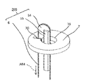
- FIG. 13 is a detailed view of a main part showing the wire feeding mechanism 200 of the wire electric discharge machine according to the fifth embodiment.
- the wire feeding mechanism 200 includes a wire 8, a wire reversing portion 14, and a holding portion 15 for holding the wire reversing portion.
- the wire reversing portion 14 has a pulley shape and has a groove formed in the circumferential portion.
- the groove of the wire reversing portion 14 is continuously formed on the side surface of the holding portion 15.
- a method of forming a microtexture 4c on the vane groove 30 by using the wire feeding mechanism 200 will be described.
- the wire feeding mechanism 200 is installed in the wire electric discharge machine.
- the wire 8 is stretched along the grooves of the wire reversing portion 14 and the holding portion 15 of the wire feeding mechanism 200, and is connected to the wire electric discharge machine.
- a cylinder 7 having a vane groove 30 is installed in the wire electric discharge machine.
- the wire 8 is driven in the direction of the arrow AR4 while maintaining a constant tension along the wire feeding mechanism 200, and is discharged from the wire 8 to the vane groove 30.
- the arrow AR4 direction indicates the downward direction on the paper in FIG. 13, it may be the upward direction. That is, the arrow AR4 direction may be the extending direction of the microtexture 4.
- the cylinder chamber 70 of the new cylinder 7 is installed through the wire reversing portion 14 from the paper surface direction.
- the fifth embodiment even when the vane groove 30 is in a closed space, the next vane is not inserted and cut each time the wire 8 is processed.
- the microtexture 4 can be formed in the groove 30. Therefore, the time for forming the microtexture 4 with respect to the vane groove 30 can be shortened.
- the wire reversing portion 14 may be configured to rotate to feed the wire 8, but may be configured to feed the wire 8 while being fixed.
- microtextures 4 of the opposing sliding surfaces 31 are in the same vertical position, that is, in a symmetrical positional relationship, but it is not always necessary.
- the sliding mechanism 1 is provided in the compressor 100 , but it may be provided in a journal bearing, a rotary pump, or the like.
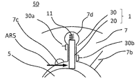
- FIG. 14 is an enlarged plan view showing a part of the compressor 100 according to the sixth embodiment.
- FIG. 14 shows an enlarged view of the periphery of the vane 20.
- a force is always applied to the vane 20 in the direction indicated by the arrow AR5 in FIG. This is because the piston 5 and the vane 20 slide by rotating the piston 5 in a certain direction (clockwise in FIG. 14).
- the left side of the vane 20 is divided into the discharge side of the refrigerant and the right side is divided into the suction side, and the pressure difference of the refrigerant in the AR5 direction also exerts a force on the vane 20 in the AR5 direction.
- the pressure applied to the vane groove 30 by the vane 20 is not uniform in the sliding direction, and the region corresponding to the end of the vane 20 on the sliding surface 31 is compared with the other regions on the sliding surface 31. High pressure is applied. That is, on the sliding surface 31, the regions 30a and 30b shown in FIG. 14 are subjected to higher pressure than the other regions.
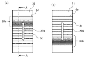
- FIG. 15 is a schematic view showing the microtexture 4e of the sliding mechanism 1 according to the sixth embodiment.
- FIG. 15A shows an example in which the microtexture 4e is formed on the left side surface of the vane groove 30, and
- FIG. 15B shows an example in which the microtexture 4e is formed on the right side surface of the vane groove 30.
- An example is shown.
- the microtexture 4e is in the other region in the region 30a on the outer diameter side of the cylinder 7 in the sliding direction. It is densely formed in comparison.
- the microtexture 4e is densely formed in the region 30b on the inner side in the sliding direction, that is, on the inner diameter side of the cylinder 7, as compared with the other regions.
- the microtexture 4e according to the present embodiment has a different distribution in the sliding direction.
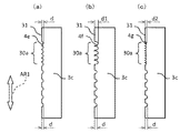
- FIG. 16 is a schematic view showing the microtextures 4e, 4f, and 4g of the sliding mechanism 1 according to the sixth embodiment.
- FIG. 16A shows the cross section AA in FIG. 15A, in which microtextures 4e having the same groove width and groove depth are densely formed in the region 30a.
- the microtexture 4f formed in the region 30a has a wider groove width and a deeper groove depth than the microtexture 4f formed in another region.
- the microtexture 4g formed in the region 30a has a smaller groove width and a shallower groove depth than the microtexture 4g formed in the other regions. There is.
- the combination of the groove width and the groove depth of the groove is a combination of the formation examples of the microtextures 4e, 4f, and 4g shown in FIGS. 16 (a), 16 (b), and 16 (c). You may.
- the distribution of the microtexture described above is the same for the region 30b. It should be noted that the groove width and the groove depth of these grooves can be realized by the wire 8 replacement function and the discharge time control function of the wire electric discharge machine as described above.
- Embodiment 7 As shown in FIG. 13 and the like, the wire 8 of the wire electric discharge machine runs in a space close to the vane groove 30 in a state of being stretched by a predetermined tension.
- the method for manufacturing the sliding mechanism 1 according to the present embodiment uses a wire guide holding mechanism so that the wire 8 does not fluctuate in the formation of the sliding mechanism 1.
- FIG. 17 is an explanatory diagram illustrating a method of processing the microtexture 4 on the sliding member accommodating portion 3 of the compression mechanism portion 50 according to the seventh embodiment.
- 17 (a), 17 (b), and 17 (c) show a perspective view, a side view, and a top view, respectively.
- FIG. 17B shows a view of the wire 8 from the center side of the cylinder 7, that is, from the main shaft 6 side along the X-axis direction shown in FIG. 17A, and is shown in FIG. 17C. Shows a view of the wire 8 seen from above the cylinder 7 along the Y-axis direction shown in FIG. 17 (a).
- the wire guide 60a is connected to a wire guide holding mechanism (not shown) below the paper surface in FIG. 17 (c). Further, the guide portion 61a in contact with the wire 8 is a flat surface.
- the guide portion 61a may be provided with a guide groove (not shown) having a groove depth of about half the cross section of the wire 8 extending in the Y direction so that the wire 8 does not fluctuate in the X direction during traveling. good.
- the case where the guide groove is provided in the guide portion 61a is also referred to as a flat surface.
- the wire 8 is subjected to a predetermined tension in the vertical direction, that is, in the Y-axis direction, and travels while being stretched to the left with respect to the wire guide 60a, that is, in the negative direction of the Z-axis.
- the wire 8 is fixed without being separated from the wire guide 60a, in other words, the wire 8 can be accurately discharged to the vane groove 30 without changing the spatial position with the vane groove 30.
- the microtexture 4e can be accurately formed by using the wire guide 60a.
- rotational deviation around the Y axis in FIG. 17 corresponds to the deviation of the distance while the wire 8 is kept parallel to the sliding surface 31, so that it can be easily adjusted each time the discharge occurs.
- wire guide 60a it is possible to configure the wire guide 60a and the wire feeding mechanism (not shown) separately from the electric discharge machine. Further, by using the wire guide 60a, it is also possible to use a die-sinking type electric discharge machine. Generally, wire electric discharge machines use pure water as the machining fluid during electric discharge, but on the other hand, die-sinking electric discharge machines use oil, so due to the difference in this machining fluid, the die-sinking electric discharge machines use wires. Higher precision machining is possible compared to electric discharge machines.
- Embodiment 8 The microtexture 4 according to the present embodiment is formed on the sliding surface 31 by using the wire guide 60b as in the seventh embodiment.
- the shape of the wire guide 60b used in the process of forming the microtexture 4 is different from that of the seventh embodiment.
- the same components as those in the seventh embodiment are designated by the same reference numerals, and the description thereof will be omitted.
- FIG. 18 is an explanatory diagram showing a comparative example of the microtexture processing method according to the eighth embodiment.
- FIG. 18A shows an example when the wire guide 60a is tilted. Specifically, the wire 8 is tilted together with the wire guide 60a in the direction of the arrow AR6 around the X axis, that is, in a direction in which parallelism with the sliding surface 31 cannot be maintained.
- FIG. 18B shows the microtexture 4e1 formed on the sliding surface 31 in the above-mentioned state as a comparative example.
- the microtexture 4e1 becomes wedge-shaped and is biased toward one side of the sliding surface 31 (plus side in the Y-axis direction in FIG. 18). That is, on one side of the sliding surface 31, the groove width and the groove depth of the microtexture 4e1 are large, and the groove width and the groove depth of the microtexture 4e1 toward the other side (minus side in the Y-axis direction in FIG. 18). It is formed in a discontinuous shape while the groove depth becomes smaller.
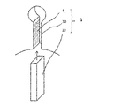
- the wire guide 60b has a guide portion 61b formed in a convex shape.
- the guide portion 61b has a curvature, for example, and is formed so as to have a gently convex shape.
- the shape having a curvature is referred to as an arc shape.
- FIG. 19 is an explanatory diagram showing a comparative example of the microtexture processing method according to the eighth embodiment.
- FIG. 19A shows an example in which the wire guide 60b is tilted, as in FIG. Specifically, the wire 8 is tilted together with the wire guide 60b in the direction of the arrow AR6 around the X axis, that is, in a direction in which parallelism with the sliding surface 31 cannot be maintained.
- FIG. 19B shows the microtexture 4e2 formed on the sliding surface 31 in the above-mentioned state as a comparative example.
- the microtexture 4e2 is also formed unevenly toward one side of the sliding surface 31 (plus side in the Y-axis direction in FIG. 19), similarly to the microtexture 4e1 shown in FIG. 18B.
- FIG. 20 is an explanatory diagram illustrating a method of processing the microtexture 4e3 into the sliding member accommodating portion 3 of the compression mechanism portion 50 according to the eighth embodiment.
- FIG. 20A shows a state in which the position of the wire guide 60b shown in FIG. 19A is corrected.
- FIG. 20B shows a microtexture 4e3 formed on the sliding surface 31 in a state where the position of the wire guide 60b shown in FIG. 20A is corrected.
- the wire guide 60b is tilted in the direction of the arrow AR6 around the X axis in FIG. 20, since the guide portion 61b has a convex shape, it is moved in the direction of the arrow AR7 (Y-axis direction in FIG. 20). Then, the position of the microtexture 4e3 can be easily adjusted. In the example shown in FIG. 20, the wire guide 60b shown in FIG. 19A is moved to the minus side in the Y-axis direction.
- the microtexture 4e3 can be formed on the sliding surface 31 without the need for adjusting the inclination in the AR6 direction.
- the processing accuracy of the microtexture 4h is improved.
- the groove depth dimension and the groove width dimension may be changed for each microtexture constituting the microtexture h.
- FIG. 21 is a schematic view showing the microtexture 4h of the sliding mechanism 1 according to the eighth embodiment.
- the microtexture 4h formed by using the wire guide 60b in which the guide portion 61b has a convex shape has a groove width and a groove depth at the center portion in the Y-axis direction of the sliding surface 31 shown in FIG. Is big.
- the groove width of the microtexture 4h is narrow and the groove depth is shallow. Further, the microtexture 4h does not extend to the end of the sliding surface 31.
- the lubricating oil is held in each of the microtexture 4h, and the amount of the lubricating oil discharged from the end of the microtexture 4h to the outside of the sliding surface 31 is small, and the effect of oil pooling can be obtained. This improves the lubricity of the sliding member 2.
- a wire discharge grinding method is known as a processing method using a wire guide, but the wire discharge grinding method is a method of discharging between the apex of the convex portion of the wire guide and the workpiece. ..
- the wire discharge grinding method is a method of discharging between the apex of the convex portion of the wire guide and the workpiece. ..
- the processing method according to the present embodiment when the wire 8 in contact with the wire guide 60b discharges to the sliding surface 31, the discharge from the wire 8 is only from the convex apex of the wire guide 60b. Instead, discharge occurs in a part of the wire 8 where the distance from the sliding surface 31 is equal to or less than the discharge gap at the portion where the wire 8 abuts on the wire guide 60b. This makes it possible to form linear microtextures rather than dotted ones.
- FIG. 22 is an explanatory diagram showing the wire guide 60b according to the eighth embodiment.
- the length of the microtexture 4h shown in FIG. 21 in the Y-axis direction (hereinafter referred to as “groove length”) is, for example, 20 mm, 10 to 60 ⁇ m is appropriate for the deepest groove depth in the central portion. be. That is, the relationship between the groove length of the microtexture 4h and the groove depth is 1000: 0.5 to 1000: 3, and the groove depth of the microtexture 4h is a maximum of 0.3% of the groove length.
- the radial dimension of the arc shape of the wire guide 60b is about 830 to 5000 mm. According to the study by the inventors, although it depends on the current conditions, the discharge gap is about 0.02 mm, and if the distance between the wire 8 and the sliding surface 31 is equal to or less than this discharge gap, a discharge occurs. Further, if the wire 8 is advanced in the groove depth direction together with the wire guide 60b, the groove length becomes longer.
- the convex shape of the guide portion 61b is not limited to that described above. That is, the convex shape of the guide portion 61b has a curvature and is not limited to the arc shape formed so as to have a gentle convex shape.
- FIG. 22 is an explanatory diagram showing the wire guide 60b according to the eighth embodiment.
- FIG. 22 schematically shows a view of the possible cross-sectional shape of the wire guide 60b as viewed from the X-axis direction.
- the convex shape of the guide portion 61b may be an arc shape shown in FIG. 22 (a), an elliptical shape shown in FIG. 22 (b), or a combination of a straight line and an arc shape shown in FIG. 22 (c).
- FIG. 23 is an explanatory diagram showing the positional relationship between the wire 8 and the sliding surface 31 according to the ninth embodiment.
- FIG. 23A shows a cross section taken along the line BB shown in FIG. 17C
- FIG. 23B shows a microtexture 4j formed on the sliding surface 31.
- the angle in the extending direction of the microtexture 4j is the sliding direction of the sliding member 2. It is formed so as to be inclined at an angle other than 90 ° with respect to a certain arrow AR1.
- the microtexture 4j is formed by inclining the wire guide in the direction of the arrow AR6 around the X axis or moving the wire guide 60b in the direction of the arrow AR7 (Y-axis direction shown in FIG. 24).
- the position of the AR7 direction can be set arbitrarily.
- FIG. 24 is an explanatory diagram showing the microtexture 4k of the sliding mechanism 1 according to the ninth embodiment.
- FIGS. 24 (a) and 24 (b) show examples of microtextures 4k and 4 m formed on the sliding surface 31, respectively.
- FIG. 24A shows an example in which the microtexture 4k is formed on the sliding surface 31 by aligning the angle at which the microtexture 4k is inclined and the direction in which the microtexture 4k is arranged.
- FIG. 24B shows an example in which the microtexture 4m is formed on the sliding surface 31 at different angles at which the microtexture 4m is inclined.
- the component in the same direction as the arrow AR1 which is the sliding direction in the direction in which the microtexture 4 m is inclined that is, the X-axis direction shown in FIG. 24 (b). Since it has a component, the movement and circulation of the lubricating oil easily proceed with the sliding of the sliding member, whereby an oil film having good friction characteristics can be formed.
- the direction in which the microtextures 4k and 4m are inclined is the X-axis direction in the example shown in FIG. 24.
- a portion having a small groove width and groove depth at the end of the microtexture that is, the vicinity of the center in the Y-axis direction on the sliding surface 31 is arranged so as to overlap in the AR1 direction.
- the total area of the microtexture 4m is uniformly arranged in the AR7 direction (Y-axis direction), which is the width direction of the sliding surface 31, the retention of the oil film is stabilized in the entire sliding surface 31, and the friction characteristics are improved. You can get stability.
Landscapes
- Engineering & Computer Science (AREA)
- Mechanical Engineering (AREA)
- General Engineering & Computer Science (AREA)
- Chemical & Material Sciences (AREA)
- Chemical Kinetics & Catalysis (AREA)
- Electrochemistry (AREA)
- Applications Or Details Of Rotary Compressors (AREA)
- Electrical Discharge Machining, Electrochemical Machining, And Combined Machining (AREA)
Abstract
摺動部材収容部に潤滑油を保持できる摺動機構、圧縮機、摺動機構の製造方法及び圧縮機の製造方法を提供する。 摺動機構に、対向する一対の摺動面(31)を有する摺動部材収容部(3)と、潤滑油を介して、一対の摺動面(31)の間に摺動自在に配置される摺動部材(2)と、を備え、摺動部材収容部(3)の一対の摺動面(31)の少なくとも一方は、摺動部材(2)の摺動方向に対して交差する方向に延在し、放電痕(4d)が形成された溝部(4)を備えたものであると、摺動部材収容部に潤滑油を保持できる。
Description
本開示は、摺動機構、圧縮機、摺動機構の製造方法及び圧縮機の製造方法に関する。
圧縮機の摺動機構において、ブレード案内溝(以下、「摺動部材収容部」という)及びブレード(以下、「摺動部材」という)に、マスキング及びショットブラストによってくぼみや溝等の潤滑油の保持部を形成し、摺動部材収容部及び摺動部材の摺動壁(以下、「摺動面」という)の磨耗及び焼付きを抑制する技術が開示されている(例えば、特許文献1)。
しかしながら、特許文献1には、摺動部材収容部の摺動面に、マスキング及びショットブラストによってどのように潤滑油の保持部(以下、「溝部」という)を形成するかは記載されていない。摺動部材収容部は閉じられた狭小な空間であることから、これらの方法では、工具や装置を摺動部材収容部に入れることができないという課題があった。そのため、摺動部材収容部に潤滑油を保持する溝部を形成することは困難であり、特許文献1に記載の摺動機構において、摺動部材収容部に潤滑油を十分に保持できないという課題があった。
本開示は、上記のような課題を解決するためになされたものであり、摺動部材収容部に潤滑油を保持できる摺動機構、圧縮機、摺動機構の製造方法及び圧縮機の製造方法を提供することを目的とする。
本開示にかかる摺動機構は、対向する一対の摺動面を有する摺動部材収容部と、
潤滑油を介して、一対の摺動面の間に摺動自在に配置される摺動部材と、を備え、
摺動部材収容部の一対の摺動面の少なくとも一方は、摺動部材の摺動の方向に対して交差する方向に延在し、放電痕が形成された溝部を有するものである。
潤滑油を介して、一対の摺動面の間に摺動自在に配置される摺動部材と、を備え、
摺動部材収容部の一対の摺動面の少なくとも一方は、摺動部材の摺動の方向に対して交差する方向に延在し、放電痕が形成された溝部を有するものである。
本開示にかかる圧縮機は、内部にシリンダ室、冷媒が吸入される吸入孔、及び圧縮された冷媒が吐出される吐出孔を有する円筒状であり中空状のシリンダと、シリンダ室に配置され、偏心回転に伴ってシリンダ室に冷媒を吸入するとともに、圧縮された冷媒を吐出するピストンと、を備え、シリンダは、本開示に記載の摺動機構を有するものである。
本開示にかかる摺動機構の製造方法は、ワイヤ放電加工機に、一対の摺動面を有する摺動部材収容部を有する被加工対象を設置する工程と、摺動部材収容部の、一対の摺動面に対して平行且つ摺動部材の摺動方向と交差する方向に、ワイヤ放電加工機にワイヤを張架する工程と、ワイヤを放電させ、放電されたワイヤによって、一対の摺動面の少なくとも一方に溝部を形成する工程と、を有するものである。
本開示にかかる圧縮機の製造方法は、ワイヤ放電加工機に、一対の摺動面を有する摺動部材収容部を有し、円筒状であり中空状のシリンダを設置する工程と、摺動部材収容部の、一対の摺動面に対して平行且つ摺動部材の摺動方向と交差する方向に、ワイヤ放電加工機にワイヤを張架する工程と、ワイヤを放電させ、放電されたワイヤによって、一対の摺動面の少なくとも一方に溝部を形成する工程とを有するものである。
本開示によれば、摺動部材収容部に潤滑油を保持できる。
以下に添付図面を参照しながら、本開示の好適な実施の形態について詳細に説明する。
なお、本開示は以下の記述に限定されるものではなく、本開示の要旨を逸脱しない範囲において適宜変更可能である。また、本明細書及び図面において、実質的に同一の機能を有する構成要素については、同一の符号を付することにより重複説明を省略する。なお、図面において、装置の構成や部材の形状を示す図は、あくまで装置及び部材の概略的な構成及び形状を示すものである。各図面において図示される各部材の相対的な大きさ、及び相対的な位置は、必ずしも実際の部材間における大小関係及び位置関係を正確に表現するものではない。
なお、本開示は以下の記述に限定されるものではなく、本開示の要旨を逸脱しない範囲において適宜変更可能である。また、本明細書及び図面において、実質的に同一の機能を有する構成要素については、同一の符号を付することにより重複説明を省略する。なお、図面において、装置の構成や部材の形状を示す図は、あくまで装置及び部材の概略的な構成及び形状を示すものである。各図面において図示される各部材の相対的な大きさ、及び相対的な位置は、必ずしも実際の部材間における大小関係及び位置関係を正確に表現するものではない。
実施の形態1.
図1は、実施の形態1にかかる圧縮機100の一部を示す概略平面図である。図1に示すように、圧縮機100(後述する)は、ピストン5、主軸6、及び円筒状であり中空状のシリンダ7を備え、シリンダ7は、摺動機構1aを有する。摺動機構1aは、摺動面21を有する摺動部材2と、対向する一対の摺動面31を有する摺動部材収容部3aとを備える。摺動部材収容部3aは、シリンダ7の内径側から外径側に、空洞として形成される。すなわち、シリンダ7の内側の中空と連通して、摺動部材収容部3aが形成される。図1において、摺動部材収容部3は、シリンダ7の内径側に摺動面31を有し、シリンダ7の外径側は円形となっている。摺動部材2は、一端は摺動部材収容部3aの対向する一対の摺動面31の間に配置され、他端はピストン5の周壁と接している。摺動部材2とピストン5が接している箇所を、接触部51とする。摺動部材2と摺動部材収容部3aとの間には、潤滑油(図1に図示せず)が充填されている。さらに、図1には図示していないが、摺動部材収容部3aの摺動面31には、潤滑油を保持する凹状の溝であるマイクロテクスチャ4a、すなわち溝部が形成される。摺動部材収容部3aの対向する一対の摺動面31の間に摺動部材2が配置されているとき、摺動部材収容部3aの摺動面31と、摺動部材2の摺動面21はそれぞれ対向している。
図1は、実施の形態1にかかる圧縮機100の一部を示す概略平面図である。図1に示すように、圧縮機100(後述する)は、ピストン5、主軸6、及び円筒状であり中空状のシリンダ7を備え、シリンダ7は、摺動機構1aを有する。摺動機構1aは、摺動面21を有する摺動部材2と、対向する一対の摺動面31を有する摺動部材収容部3aとを備える。摺動部材収容部3aは、シリンダ7の内径側から外径側に、空洞として形成される。すなわち、シリンダ7の内側の中空と連通して、摺動部材収容部3aが形成される。図1において、摺動部材収容部3は、シリンダ7の内径側に摺動面31を有し、シリンダ7の外径側は円形となっている。摺動部材2は、一端は摺動部材収容部3aの対向する一対の摺動面31の間に配置され、他端はピストン5の周壁と接している。摺動部材2とピストン5が接している箇所を、接触部51とする。摺動部材2と摺動部材収容部3aとの間には、潤滑油(図1に図示せず)が充填されている。さらに、図1には図示していないが、摺動部材収容部3aの摺動面31には、潤滑油を保持する凹状の溝であるマイクロテクスチャ4a、すなわち溝部が形成される。摺動部材収容部3aの対向する一対の摺動面31の間に摺動部材2が配置されているとき、摺動部材収容部3aの摺動面31と、摺動部材2の摺動面21はそれぞれ対向している。
ピストン5は、主軸6周りに回転する。摺動部材2は、ピストン5との接触部51を介し、ピストン5の偏心回転に従動して、摺動部材収容部3a内を、円筒状のシリンダ7の径方向に摺動する。
図2は、実施の形態1にかかる摺動機構1aを示す分解概略図である。図2(a)は、摺動機構1aの概略斜視図、図2(b)は、摺動部材収容部3aの概略正面図である。
図2において、摺動部材収容部3aは、摺動部材2の摺動面21と潤滑油を介して対向する摺動面31を有する。摺動面31には、マイクロテクスチャ4aが形成される。マイクロテクスチャ4aは、摺動部材2の摺動方向と交差する方向に延在する。図2において、マイクロテクスチャ4aが延在する方向は、摺動部材2の摺動方向と直交している。マイクロテクスチャ4aは、潤滑油による流体膜に、正圧を発生させて摺動面21を浮上させる流体動圧効果を有する。また、マイクロテクスチャ4aは、凹状の溝に潤滑油が保持される流体保持効果を有する。また、マイクロテクスチャ4aは、摺動部材2が摺動した過程で発生した摩耗粉を、凹状の溝に捕集することにより、摩耗粉の噛み込みを抑制する摩耗粉の捕集効果を有する。さらに、マイクロテクスチャ4aは、潤滑油を保持することにより、摺動部材2及び摺動部材収容部3aの固体接触及び凝着摩耗を抑制する効果を有する。以上の効果を総合して、マイクロテクスチャ4aが摺動部材収容部3aの摺動面31に形成されることにより、摺動機構1aの耐摩擦特性の向上につながる。
図3は、実施の形態1にかかる摺動機構1aの動作を示す概略上面図である。
図3において、摺動部材2と摺動部材収容部3aとの間には、潤滑油(図3に図示せず)が介在した状態である。図1における主軸6が回転すると、これに従動するピストン5の偏心回転に伴い、摺動部材2が摺動部材収容部3aに対して摺動する。
ここで、摺動部材2が、図3の矢印AR1方向に摺動する場合について説明する。摺動部材2が矢印AR1方向に摺動するとき、潤滑油は、摺動部材2の摺動方向と同じ方向へ流れる。そして、マイクロテクスチャ4a内へ流入した潤滑油は、矢印AR2に示すように、マイクロテクスチャ4aの凹状の溝に沿って、摺動部材2へ近づく方向へ流れる。この潤滑油の流れによって、摺動部材2には、左右両方の摺動面21で摺動部材収容部3aから離れる方向へ力が加わる。これにより、摺動部材2の摺動面21と摺動部材収容部3aの摺動面31との間に生じる摺動抵抗が低減される。
なお、摺動部材2は、矢印AR1と反対方向にも摺動する。このとき、潤滑油が流れる方向は、図3の矢印AR2の反対方向になるが、摺動部材2に対して、摺動部材収容部3aから離れる方向に力が加わる点は、摺動部材2が矢印AR1方向に摺動する場合と同様である。
摺動部材収容部3aに形成されるマイクロテクスチャ4aの本数は、一方の摺動面31に1本でもよいが、図2に示すように、一方の摺動面31に複数本形成してもよい。それぞれのマイクロテクスチャ4aの間隔寸法pは、潤滑油による油膜保持に有効であるように任意に設定すればよい。また、マイクロテクスチャ4aの1本の幅及び深さ(以下、それぞれ「溝幅及び溝深さ」という)の寸法は、例えば溝幅寸法wを10~60μm、溝深さ寸法dを2~10μmとすればよい。マイクロテクスチャ4aの間隔寸法pの寸法は、例えば100~500μmとすればよい。
ここで、本開示においてマイクロテクスチャ4aを形成するワイヤ放電加工機は、本来は被加工対象の切断の用途に使われるものである。本開示においては、ワイヤ放電加工機を用いて、マイクロテクスチャ4aを形成する。そのため、本開示におけるワイヤ放電加工機の用途の使用条件は、通常用いられるワイヤ放電加工機の切断の条件と異なる。摺動部材収容部3aの間隙寸法W、すなわち、摺動面31間の距離は、例えば10mm以下である。
マイクロテクスチャ4aを摺動部材収容部3aの摺動面31に形成する場合、摺動部材収容部3aの内側から、すなわち、摺動面31と摺動面31との間にレーザ加工機等を配置して、マイクロテクスチャ4aを形成する必要がある。しかしながら、摺動部材収容部3aの間隙は狭小であり、一方の摺動面31に対してマイクロテクスチャ4aを形成しようとしても、マシニングセンタ等の加工機、レーザ加工又はフォトエッチング等の形成方法では、工具や装置が入らず、マイクロテクスチャ4aを形成することができない。
本開示では、ワイヤ放電加工機を用いることによって、摺動部材収容部3aの狭小な間隙にワイヤ放電加工機のワイヤ8を通し、放電によって摺動部材収容部3aの摺動面31にマイクロテクスチャ4aを形成することができる。そのため、ワイヤ8を通すことができれば、例えばレーザ加工機等が配置できない狭小な間隙であっても、マイクロテクスチャ4aを形成することができる。
図4は、ワイヤ放電加工機によるマイクロテクスチャ4aの形成方法を説明する図である。図4(a)は、ワイヤ放電加工機のワイヤ8と、被加工対象、例えばシリンダ7が有する摺動部材収容部3aとの位置関係を示す上面図であり、図4(b)は、摺動部材収容部3との位置関係を示す側面図である。図4(b)において、摺動部材2が摺動方向をX方向(矢印AR1方向)とし、マイクロテクスチャ4aが延在する方向をY方向とする。
すなわち、図4(b)におけるY方向とは、摺動部材2の摺動方向と直交する方向である。図4(a)におけるマイクロテクスチャ4aの位置と、図4(b)におけるマイクロテクスチャ4aの位置は対応している。図4に示す矢印AR3は、ワイヤ8の走査方向を示す。図4(c)は横軸を時間及び移動距離、縦軸を電圧とした、ワイヤ放電加工機の放電パルスの印加状態を示す図である。図4(c)の横軸は、図4(b)のX方向寸法に対応しており、パルス印加時のワイヤ放電加工機のワイヤ8の位置と対応している。
すなわち、図4(b)におけるY方向とは、摺動部材2の摺動方向と直交する方向である。図4(a)におけるマイクロテクスチャ4aの位置と、図4(b)におけるマイクロテクスチャ4aの位置は対応している。図4に示す矢印AR3は、ワイヤ8の走査方向を示す。図4(c)は横軸を時間及び移動距離、縦軸を電圧とした、ワイヤ放電加工機の放電パルスの印加状態を示す図である。図4(c)の横軸は、図4(b)のX方向寸法に対応しており、パルス印加時のワイヤ放電加工機のワイヤ8の位置と対応している。
ワイヤ放電加工機を用いてマイクロテクスチャ4aを形成し、摺動機構1を製造する方法について説明する。まず、ワイヤ放電加工機(図4に図示せず)に、被加工対象が有する摺動部材収容部3aを設置する。次に、ワイヤ8を、ワイヤ放電加工機に張架する。摺動部材収容部3aとワイヤ8との位置関係を所定の位置に設定し、放電を起こす。
そして、ワイヤ放電加工機のワイヤ8を、摺動部材収容部3aに対して平行、且つワイヤ8の走査方向、すなわち摺動部材2の摺動方向に対して交差する方向に延在するように配置され、一定速度で矢印AR3方向(X方向)に移動させる。電源(図4に図示せず)により、一定の周波数で放電を起こし、摺動部材収容部3aの摺動面31を加工する。すなわち、摺動部材収容部3aにマイクロテクスチャ4aを形成する。
なお、加工の最適条件のため、放電時にはワイヤ8のX方向の移動を停止させたり、移動速度を変化させたりしてもよい。以上により、凹状の溝であるマイクロテクスチャ4aが形成される。
図5は、実施の形態1にかかる摺動機構1のマイクロテクスチャ4aを示す断面図である。図5は、ワイヤ放電加工機のワイヤ8の延在方向に対して直交する方向の、摺動部材収容部3aの断面(以下、「溝断面」という)を示す図である。
図5に示すとおり、マイクロテクスチャ4の溝断面は、放物線に近い形状になる。例えば、φ70μmのワイヤ8を使用した場合、溝幅寸法wは、例えば30~60μm、溝深さ寸法dは、例えば2~10μmとなる。また、マイクロテクスチャ4a上に示す鋸歯状の放電痕4d(後述する)は、放電加工によって加工された加工面に一般的に見られるものである。図5は、放電設定時間が2秒の場合に形成されたマイクロテクスチャ4aを示したものであるが、加工時間が長いほど放電痕4dの大きさが小さくなるとともに数量が減り、溝断面の形状は平滑になる傾向がある。従って、マイクロテクスチャ4aの形成時には、溝断面の許容粗度と生産時間とから、最適な放電時間を設定すればよい。
図6は、実施の形態1にかかる摺動機構1のマイクロテクスチャ4aを示す顕微鏡写真である。図6は、マイクロテクスチャ4aをワイヤ8側から観察した顕微鏡写真である。
図6において、摺動部材2は、矢印AR1方向に摺動する。図6におけるマイクロテクスチャ4a形成時の放電設定時間は5秒である。一般的に、放電時間が長い方が、溝幅寸法wが均一になる傾向がある。従って、溝幅寸法wの均一性を重視する場合は、加工時間が許容できる範囲で、放電時間を長くすればよい。
図6において、摺動部材2は、矢印AR1方向に摺動する。図6におけるマイクロテクスチャ4a形成時の放電設定時間は5秒である。一般的に、放電時間が長い方が、溝幅寸法wが均一になる傾向がある。従って、溝幅寸法wの均一性を重視する場合は、加工時間が許容できる範囲で、放電時間を長くすればよい。
ところで、ワイヤ放電加工機等の放電加工機で加工を行った際、加工面は熱影響を受け、溝全体、すなわちマイクロテクスチャ4aの凹状の溝の表面には、放電加工特有の変質層(図5に図示せず)が形成される。例えば材料が鉄系の場合、変質層には、他と異なる層として、パーライト又はセメンタイト等の金属組織構成が見られる。また、例えば材料がアルミ系の場合、変質層には、白層又は微細空孔等が見られる。他の材料でも同様の放電加工特有の変質層が見られる。また、加工面には、図5で示した放電痕4dも見られる。放電痕4dは放電が当たった痕で、加工面が一度融解し再凝固した面であり、鋸歯状であり、表面が粗い。変質層及び放電痕4dは、走査型電子顕微鏡等で観察可能であり、本開示におけるマイクロテクスチャ4aの加工面の特徴と言える。なお、放電痕4dは微細なため、マイクロテクスチャ4aにおいて観察されない場合もある。
上述のように、摺動機構1は、対向する一対の摺動面31を有する摺動部材収容部3aと、潤滑油を介して、一対の摺動面31の間に摺動自在に配置される摺動部材2と、を備え、摺動部材収容部3aの一対の摺動面31の少なくとも一方は、摺動部材2の摺動方向に対して交差する方向に延在するマイクロテクスチャ4aを有するものである。
以上のように、ワイヤ放電加工機を用いることにより、摺動機構1aは、対向する一対の摺動面31を有する摺動部材収容部3aに、マイクロテクスチャ4aを形成できるため、摺動部材収容部3aに潤滑油を保持できる。
また、摺動機構1は、ワイヤ放電加工機により加工されるため、上述のとおり摺動部材収容部3aの間隙寸法W0が、例えば10mm以下で、マシニングセンタ、レーザ加工又はフォトエッチング等では加工できないほど狭小でも、摺動部材収容部3aの摺動面31に容易にマイクロテクスチャ4aを加工することができる。
また、ワイヤ放電加工機は、1μm単位の一定の距離を保ちながら、ワイヤ8と摺動部材収容部3とが非接触の状態で、摺動部材収容部3aの摺動面31にマイクロテクスチャ4aを形成できる。したがって、マイクロテクスチャ4aの溝幅及び溝深さを、1μm単位の高精度で設計し、形成することができる。
また、摺動機構1aは、ワイヤ放電加工機により加工されるため、マシニングセンタ等の加工工具の摩耗交換を気にする必要がない。そのため、加工コストを低減できる。
また、摺動機構1aは、ワイヤ放電加工機により加工されるため、マイクロテクスチャ4aの溝幅寸法又はピッチ寸法等の形状仕様を、金型又はフィルム等で用意する必要がない。また、必要によっては、個別にマイクロテクスチャ4aの溝幅寸法及びピッチ寸法を変えることも可能であるため、より最適なマイクロテクスチャ4aを得ることができる。
また、摺動機構1aは、ワイヤ放電加工機により加工されるため、マイクロテクスチャ4aの加工面は放電痕により粗くなり、より多くの潤滑油を保持することができる。
また、摺動機構1aは、ワイヤ放電加工機により加工されるため、マシニングセンタ等の加工工具による加工と異なり、非接触加工のため加工力がかからず、摺動部材収容部3aが硬脆材料であっても加工時にクラック等の欠陥が入りにくく、欠陥の発生を抑制できる。
また、摺動機構1aは、摺動部材2の摺動に伴う損失を抑制できるため、摺動部材2及び摺動部材収容部3aの長寿命化を図ることができる。
また、摺動機構1aは、摺動部材収容部3aがマイクロテクスチャ4aを有するため、潤滑油を介して対向する摺動部材2との耐摩擦特性を向上させることができ、摺動抵抗の増加を抑制することができる。
実施の形態2.
図7は、実施の形態2にかかる摺動機構1bのマイクロテクスチャ4bを示す図である。図7において、摺動部材2は、矢印AR1方向に摺動する。図7(a)は、マイクロテクスチャ4bをワイヤ8側から観察した顕微鏡写真である。図7(b)は、図7(a)を模式的に示した図である。図7におけるマイクロテクスチャ4b形成時の放電設定時間は1秒である。実施の形態1の図6におけるマイクロテクスチャ4aよりも、放電設定時間を短くすることにより、マイクロテクスチャ4bの溝幅を不均一にすることができ、1本のマイクロテクスチャ4bの中で、溝幅寸法が狭い溝幅寸法w1の部分と、溝幅寸法が広い溝幅寸法w2の部分とを得ることができる。
図7は、実施の形態2にかかる摺動機構1bのマイクロテクスチャ4bを示す図である。図7において、摺動部材2は、矢印AR1方向に摺動する。図7(a)は、マイクロテクスチャ4bをワイヤ8側から観察した顕微鏡写真である。図7(b)は、図7(a)を模式的に示した図である。図7におけるマイクロテクスチャ4b形成時の放電設定時間は1秒である。実施の形態1の図6におけるマイクロテクスチャ4aよりも、放電設定時間を短くすることにより、マイクロテクスチャ4bの溝幅を不均一にすることができ、1本のマイクロテクスチャ4bの中で、溝幅寸法が狭い溝幅寸法w1の部分と、溝幅寸法が広い溝幅寸法w2の部分とを得ることができる。
マイクロテクスチャ4bにおいて、溝幅寸法w2が溝幅寸法w1よりもおおよそ20%以上大きくすれば、溝幅寸法w2の部分が、潤滑油が溜まる油溜まり部41として作用し、耐摩擦特性を向上できる。すなわち、放電設定時間を短くすることにより、意図的に溝幅を不均一にし、溝幅の広い油溜まり部41を形成することができる。油溜まり部41は、マイクロテクスチャ4bにおいて、摺動部材2の摺動方向に窪んだ部分を指す。
上述のように、マイクロテクスチャ4bは、マイクロテクスチャ4bが延在する方向と交差する方向に窪んだ油溜まり部41を有する。
以上のように、ワイヤ放電加工機を用いることにより、摺動機構1bは、対向する一対の摺動面31を有する摺動部材収容部3aに、マイクロテクスチャ4bを形成できるため、摺動部材収容部3bに潤滑油を保持できる。
また、実施の形態1と同様の効果に加え、実施の形態2では、油溜まり部41によって、より多くの潤滑油をマイクロテクスチャ4bに保持するができるため、摺動機構1bの耐摩擦特性が向上できる。
また、実施の形態2は、実施の形態1よりも放電設定時間を短くできるとともに、油溜まり部41を別工程で加工する必要がないため、マイクロテクスチャ4bの加工時間を短くすることができ、生産性を向上できる。
また、発明者らは、マイクロテクスチャ4bの溝幅及び溝深さが、放電時間に敏感に反応し、放電時間にほぼ比例して変化することを見出した。さらに、発明者らは、マイクロテクスチャ4bの溝幅は、ほぼワイヤ8のワイヤ径に比例し、ワイヤ径の半分程度であることを確認した。これらから、マイクロテクスチャ4bの溝幅及び溝深さの制御は、ワイヤ放電加工機が、ワイヤ8の交換機能及び放電時間の制御機能を有することにより実現可能である。
実施の形態3.
図8は、実施の形態3にかかる摺動機構1cのマイクロテクスチャ4cを示す概略図である。実施の形態1及び2において、マイクロテクスチャ4a及び4bは、摺動部材2の摺動方向である矢印AR1方向と直交する方向に延在している。すなわち、実施の形態1及び2において、マイクロテクスチャ4a及び4bの延在方向の角度、すなわちワイヤ放電加工機のワイヤ8の延在方向の角度は、摺動部材2の摺動方向である矢印AR1に対して90°である。一方、実施の形態3では、マイクロテクスチャ4cの延在方向の角度は、摺動部材2の摺動方向である矢印AR1に対して90°以外の角度に傾斜して形成される。さらに、図8では、加工時における電源の周波数を任意に設定することにより、一定ではない任意の間隔でマイクロテクスチャ4bを形成できることを用いて、摺動部材収容部3cの摺動面31にマイクロテクスチャ4cを形成している。
図8は、実施の形態3にかかる摺動機構1cのマイクロテクスチャ4cを示す概略図である。実施の形態1及び2において、マイクロテクスチャ4a及び4bは、摺動部材2の摺動方向である矢印AR1方向と直交する方向に延在している。すなわち、実施の形態1及び2において、マイクロテクスチャ4a及び4bの延在方向の角度、すなわちワイヤ放電加工機のワイヤ8の延在方向の角度は、摺動部材2の摺動方向である矢印AR1に対して90°である。一方、実施の形態3では、マイクロテクスチャ4cの延在方向の角度は、摺動部材2の摺動方向である矢印AR1に対して90°以外の角度に傾斜して形成される。さらに、図8では、加工時における電源の周波数を任意に設定することにより、一定ではない任意の間隔でマイクロテクスチャ4bを形成できることを用いて、摺動部材収容部3cの摺動面31にマイクロテクスチャ4cを形成している。
図9は、実施の形態3にかかる摺動機構1cのマイクロテクスチャ4c1を示す概略図である。図9に示すように、摺動部材収容部3の摺動面31に、摺動部材2の摺動方向に対して異なる角度で延在する複数のマイクロテクスチャ4c1を形成してもよい。
以上のように、ワイヤ放電加工機を用いることにより、摺動機構1cは、対向する一対の摺動面31を有する摺動部材収容部3cに、マイクロテクスチャ4c又は4c1を形成できるため、摺動部材収容部3cに潤滑油を保持できる。
また、実施の形態1と同様の効果に加え、実施の形態3では、マイクロテクスチャ4c又は4c1の方向に摺動方向である矢印AR1と同一方向の成分があるため、摺動に連れて潤滑油の移動及び循環が進みやすく、より摩擦特性のよい油膜を形成できる。
また、複数のマイクロテクスチャ4cを形成する場合、1本1本のマイクロテクスチャ4cの摺動部材2の摺動方向である矢印AR1に対する角度及び各マイクロテクスチャ4cの間隔を任意に設定することができるため、油膜形成に最適なマイクロテクスチャ4cを得ることができる。
なお、実施の形態3において、図9に示すように、マイクロテクスチャ4c1同士が交差する場合、摺動機構1cは、より摺動部材収容部3cに潤滑油を保持できる。
実施の形態4.
図10は、実施の形態4にかかる圧縮機100を示す縦断面図である。圧縮機100は、ロータリ型に分類される。図11は、実施の形態4にかかる圧縮機100の圧縮機構部50を示す拡大平面図である。図12は、実施の形態4にかかる圧縮機構部50を示す要部拡大図である。
図10は、実施の形態4にかかる圧縮機100を示す縦断面図である。圧縮機100は、ロータリ型に分類される。図11は、実施の形態4にかかる圧縮機100の圧縮機構部50を示す拡大平面図である。図12は、実施の形態4にかかる圧縮機構部50を示す要部拡大図である。
図10において、圧縮機100は、密閉容器110内に、電動機部40及び圧縮機構部50を収納している。電動機部40及び圧縮機構部50は、主軸6を介して連結されている。また、密閉容器110内の底部には、潤滑油(図示せず)が貯蓄されている。
圧縮機構部50は、図10及び図11に示すように、シリンダ7と、上軸受9及び下軸受10と、主軸6と、ピストン5と、を備える。円筒状であり中空状のシリンダ7は、図11に示すように、円形の空間であるシリンダ室70を有する。シリンダ室70には、シリンダ室70に連通し、径方向に延びる摺動部材収容部としてのベーン溝30が、シリンダの軸方向に貫通して設けられている。ベーン溝30には、摺動部材としてのベーン20が摺動自在に配置されている。また、ベーン溝30には、ベーン溝30の基部に吐出圧及び潤滑油を導く背圧室7dが設けられている。ベーン20において、背圧室7dに設けられるとともにシリンダ7の外径側の端部に接するバネ11によって、シリンダ7の内径側の端部は、ピストン5に押し付けられている。
また、シリンダ7には、圧縮機100に設けられた吸入管12からの吸入冷媒が通る吸入孔7bが、シリンダ7の外周面からシリンダ室70に貫通して設けられており、吸入孔7bを介して、吸入空間7eに冷媒を吸入する。また、シリンダ7の内周に設けられた排出空間7fから連通して、シリンダ7の内周面を切り欠いた吐出孔7cが設けられている。吐出孔7cは、吐出管13に通じている。
さらに、圧縮機構部50は、図12に示すように、摺動部材としてのベーン20と、摺動部材収容部としてのベーン溝30と、を有し、ベーン溝30には、マイクロテクスチャ4が形成されている。図12において、ベーン溝30は、シリンダ7の内径側に摺動面31を有し、シリンダ7の外径側は円形となっている。ここで、マイクロテクスチャ4とは、実施の形態1~3で説明したマイクロテクスチャ4a、4b及び4cの少なくともいずれかを指すものである。
次に、圧縮機100の動作について説明する。密閉容器110内において電動機部40が運転されると、主軸6を介してピストン5が駆動される。ピストン5の偏心回転に伴って冷媒がシリンダ室70内に吸入されると、冷媒は圧縮され、吐出される。ベーン20は、ベーン溝30の内側に配置された状態で、シリンダ室70内における吸入空間7eと排出空間7fとを隔てる隔壁として機能する。ベーン20は、シリンダ7の内周側がピストン5の周壁に当接した状態で、ピストン5の偏心回転に伴ってベーン溝30内を摺動する。
ここで、摺動部材収容部3としてのベーン溝30の内壁、すなわち、摺動面31には、マイクロテクスチャ4が形成されている。これにより、ベーン20がベーン溝30内を摺動する際のベーン20の外壁、すなわち摺動面21と、ベーン溝30の内壁、すなわち摺動面31との摺動抵抗を低減できる。
以上のように、圧縮機100は、内部にシリンダ室70、冷媒が吸入される吸入孔7b、及び圧縮された前記冷媒が吐出される吐出孔7cを有する円筒状であり中空状のシリンダ7と、シリンダ室70に配置され、偏心回転に伴ってシリンダ室70に冷媒を吸入するとともに、圧縮された冷媒を吐出するピストン5と、を備え、シリンダ7は、摺動機構1を有するものである。ここで、摺動機構1とは、実施の形態1~3で説明した摺動機構1a、1b及び1cの少なくともいずれかを指すものである。
そして、圧縮機100の製造方法は、ワイヤ放電加工機に、一対の摺動面31を有するベーン溝30を有し、円筒状であり中空状のシリンダ7を設置する工程と、ベーン溝30の、一対の摺動面31に対して平行且つベーン20の摺動方向と交差する方向に、ワイヤ放電加工機にワイヤ8を張架する工程と、ワイヤ8を放電させ、放電されたワイヤ8によって、一対の摺動面31の少なくとも一方にマイクロテクスチャ4を形成する工程とを有するものである。
圧縮機100は、摺動機構1を有しているため、実施の形態1~3に記載の効果と同様に、マイクロテクスチャ4が形成されたベーン溝30と、潤滑油を介して対向するベーン20の耐摩擦特性を向上させることができ、摺動抵抗の増加を抑制できる。
また、摺動機構1の摺動に伴う損失を抑制でき、ベーン20、ベーン溝30及び圧縮機100の長寿命化を図ることができる。
また、シリンダ室70を仕切っているベーン20は、高圧ガスにより大きな負荷がかかっており、摺動損失が大きい。しかしながら、摺動機構1を備えた圧縮機100は、ワイヤ放電加工機によりベーン溝30側にマイクロテクスチャ4が形成されているため、常に高圧ガスと接して潤滑油の油膜が剥離しやすいベーン20の外壁のみにマイクロテクスチャ4が形成されている場合よりも、潤滑油による油膜の保持力に優れ、ベーン20との摺動損失を低減できる。これにより、圧縮機100の性能を向上させ、ベーン20及びベーン溝30の摩耗を抑制できる。
また、ベーン20とベーン溝30との間に生じる摺動抵抗が大きくなると、ベーン20が鉛直下方へ移動する際の移動速度が低下してしまい、ベーン20の移動がピストン5の偏心回転に追従できず、ベーン20の下端部とピストン5の周壁との間に空隙が発生してしまうおそれある。この場合、吸入空間7eと排出空間7fとが繋がってしまうため、圧縮機100の圧縮効率が低下してしまう。
これに対して、圧縮機100では、ベーン溝30の内壁に、マイクロテクスチャ4が形成されているため、ベーン20とベーン溝30との間に生じる摺動抵抗が低減される。そのため、ベーン20が鉛直下方へ移動する際の移動速度が向上する。したがって、ベーン20の下端部とピストン5の周壁との間に空隙が生じることを抑制できるので、圧縮機100の圧縮効率が改善される。
また、圧縮機100の圧縮効率が改善されることにより、環境負荷の低減を図ることができる。
なお、実施の形態4において、マイクロテクスチャ4をワイヤ放電加工機によって形成する際、図11に示すように被加工対象であるシリンダ7が有するベーン溝30が閉空間にある場合、加工前にワイヤ8をベーン溝30の開口部に挿入する必要がある。また、加工後はワイヤ8を切断して、次の被加工対象であるシリンダ7が有するベーン溝30で、再度、ワイヤ8を通す必要がある。しかしながら、これらの操作は、ワイヤ放電加工機では一般的に自動化されており、実施の妨げになるものではない。
実施の形態5.
図13は、実施の形態5にかかるワイヤ放電加工機のワイヤ送り機構200を示す要部詳細図である。ワイヤ送り機構200は、ワイヤ8と、ワイヤ反転部14と、ワイヤ反転部を保持する保持部15と、を備える。ワイヤ反転部14は、プーリ形状で、円周部に溝が形成されている。ワイヤ反転部14の溝は、保持部15の側面に連続して形成される。
ワイヤ送り機構200を用いることにより、ワイヤ放電加工機のワイヤ8の挿入及び切断をせずに、連続してベーン溝30にマイクロテクスチャ4cを形成することができる。
図13は、実施の形態5にかかるワイヤ放電加工機のワイヤ送り機構200を示す要部詳細図である。ワイヤ送り機構200は、ワイヤ8と、ワイヤ反転部14と、ワイヤ反転部を保持する保持部15と、を備える。ワイヤ反転部14は、プーリ形状で、円周部に溝が形成されている。ワイヤ反転部14の溝は、保持部15の側面に連続して形成される。
ワイヤ送り機構200を用いることにより、ワイヤ放電加工機のワイヤ8の挿入及び切断をせずに、連続してベーン溝30にマイクロテクスチャ4cを形成することができる。
ベーン溝30に対して、ワイヤ送り機構200を用いてマイクロテクスチャ4cを形成する方法について説明する。まず、ワイヤ送り機構200をワイヤ放電加工機に設置する。次に、ワイヤ8を、ワイヤ送り機構200のワイヤ反転部14及び保持部15の溝に沿って張架するとともに、ワイヤ放電加工機に接続する。そして、ワイヤ放電加工機に、ベーン溝30を有するシリンダ7を設置する。
ワイヤ8は、ワイヤ送り機構200に沿って一定の張力を保ちながら、矢印AR4方向に駆動されるとともに、ワイヤ8からベーン溝30に対して放電する。なお、矢印AR4方向は、図13では紙面下方向を指しているが、上方向でもよい。すなわち、矢印AR4方向は、マイクロテクスチャ4の延在方向とすればよい。
ベーン溝30に対するマイクロテクスチャ4の形成が終了すると、新たなシリンダ7のシリンダ室70を、紙面上方向からワイヤ反転部14に通して設置する。
これにより、実施の形態1~4に記載の効果に加え、実施の形態5では、ベーン溝30が閉空間にある場合でも、加工の都度、ワイヤ8を挿入及び切断することなく、次のベーン溝30にマイクロテクスチャ4を形成することができる。したがって、ベーン溝30に対するマイクロテクスチャ4を形成する時間を短縮することができる。
なお、実施の形態5において、ワイヤ反転部14は、ワイヤ8を送るために回転する構成としてもよいが、固定したままワイヤ8を送る構成でもよい。
なお、本開示において、対向する摺動面31のマイクロテクスチャ4は、それぞれ同じ上下位置、すなわち左右対称の位置関係にあるが、必ずしもその必要はない。
また、本開示において、圧縮機100に摺動機構1を設ける例を示したが、ジャーナル軸受又はロータリポンプ等に設けてもよい。
実施の形態6.
図14は、実施の形態6にかかる圧縮機100の一部を示す拡大平面図である。図14には、ベーン20の周囲を拡大して示している。ベーン20には、図14中の矢印AR5に示す方向に常に力がかかる。これは、ピストン5が一定方向(図14では時計回り)に回転することで、ピストン5とベーン20が摺動するためである。また、図14においてベーン20の左側が冷媒の吐出側、右側が吸入側に分かれており、AR5方向に冷媒の圧力差が生じることによっても、ベーン20には、AR5方向に力がかかる。
図14は、実施の形態6にかかる圧縮機100の一部を示す拡大平面図である。図14には、ベーン20の周囲を拡大して示している。ベーン20には、図14中の矢印AR5に示す方向に常に力がかかる。これは、ピストン5が一定方向(図14では時計回り)に回転することで、ピストン5とベーン20が摺動するためである。また、図14においてベーン20の左側が冷媒の吐出側、右側が吸入側に分かれており、AR5方向に冷媒の圧力差が生じることによっても、ベーン20には、AR5方向に力がかかる。
そのため、ベーン20によりベーン溝30にかかる圧力は、摺動方向において均一ではなく、摺動面31におけるベーン20の端部に相当する領域には、摺動面31における他の領域に比して高い圧力がかかる。すなわち、摺動面31において、図14に示す領域30a、領域30bには、他の領域に比して高い圧力がかかる。
このことから、マイクロテクスチャ4は、領域30a及び領域30bに形成すると好ましい。図15は、実施の形態6にかかる摺動機構1のマイクロテクスチャ4eを示す概略図である。図15(a)には、マイクロテクスチャ4eを、ベーン溝30の左側面に形成した例を示しており、図15(b)には、マイクロテクスチャ4eを、ベーン溝30の右側面に形成した例を示している。図15(a)、(b)のそれぞれに示すように、ベーン溝30の一方の側面においては、摺動方向外側、すなわちシリンダ7の外径側の領域30aにマイクロテクスチャ4eが他の領域に比して密に形成さている。また、ベーン溝30の他方の側面においては、摺動方向内側、すなわちシリンダ7の内径側の領域30bにマイクロテクスチャ4eが他の領域に比して密に形成されている。このように、本実施の形態にかかるマイクロテクスチャ4eは、摺動方向において分布が異なる。
また、マイクロテクスチャ4eの分布は、マイクロテクスチャ4eの溝幅又は溝深さを変えることで変化させてもよい。図16は、実施の形態6にかかる摺動機構1のマイクロテクスチャ4e、4f、4gを示す概略図である。図16(a)は、図15(a)における断面A-Aを示しており、同じ溝幅と溝深さのマイクロテクスチャ4eが、領域30aに密に形成されている。
図16(b)に示すように、領域30aに形成されたマイクロテクスチャ4fは、他の領域に形成されたマイクロテクスチャ4fよりも溝幅が広く、溝深さが深いものになっている。一方、図16(c)に示すように、領域30aに形成されたマイクロテクスチャ4gは、他の領域に形成されたマイクロテクスチャ4gに比して、溝幅が小さく、溝深さが浅くなっている。
このようにすると、領域30aにおいて潤滑油の保持量と保持力が増し、摺動抵抗の小さい摺動機構を得ることができる。溝の溝幅、溝深さの大小の組み合わせは、図16(a)、図16(b)、及び図16(c)に示すマイクロテクスチャ4e、4f、4gの形成例を組み合わせたものであってもよい。上述したマイクロテクスチャの分布については、領域30bについても同様である。なお、これらの溝の溝幅、溝深さの大小は、前述のようにワイヤ放電加工機のワイヤ8の交換機能及び放電時間の制御機能により実現可能である。
実施の形態7.
ワイヤ放電加工機のワイヤ8は図13等に示されるように、ベーン溝30に近接する空間を予め定められた張力に張架された状態で走行している。本実施の形態にかかる摺動機構1の製造方法は、摺動機構1の形成において、ワイヤ8が変動しないようにワイヤガイド保持機構を用いるものである。
ワイヤ放電加工機のワイヤ8は図13等に示されるように、ベーン溝30に近接する空間を予め定められた張力に張架された状態で走行している。本実施の形態にかかる摺動機構1の製造方法は、摺動機構1の形成において、ワイヤ8が変動しないようにワイヤガイド保持機構を用いるものである。
図17は、実施の形態7にかかる圧縮機構部50の摺動部材収容部3へのマイクロテクスチャ4の加工方法を説明する説明図である。図17(a)、図17(b)、及び図17(c)にはそれぞれ、斜視図、側面図、及び上面図を示している。なお、図17(b)は、シリンダ7の中心側、つまり、主軸6側から図17(a)に示すX軸方向に沿ってワイヤ8を見た図を示しており、図17(c)には、シリンダ7の上方から図17(a)に示すY軸方向に沿ってワイヤ8を見た図を示している。
ワイヤガイド60aは、図17(c)における紙面下方で、図示しないワイヤガイド保持機構に接続されている。また、ワイヤ8と接触するガイド部61aは平面である。ガイド部61aには、ワイヤ8が走行時にX方向に変動しないように、ワイヤ8の断面の半分程度の溝深さを有するガイド溝(図示せず)をY方向に延在させて設けてもよい。なお、説明のため、ガイド部61aにガイド溝を設ける場合も、平面と称する。
図17(b)において、ワイヤ8は上下方向、すなわちY軸方向に予め定められた張力が加わり、ワイヤガイド60aに対して左方向、すなわちZ軸マイナス方向に張架されながら走行する。このようにすると、ワイヤ8はワイヤガイド60aから離れずに固定され、換言すればベーン溝30との空間的位置を変動させることなく、精度良くベーン溝30に放電することが可能となる。これにより、ワイヤ8の振動及びワイヤ8の形状等により、ワイヤ8の空間的位置が数μm程度変動する場合においても、ワイヤガイド60aを用いることによりマイクロテクスチャ4eを正確に形成できる。
なお、図17におけるY軸回りの回転ずれについては、ワイヤ8が摺動面31と並行を保った状態での距離のずれに相当するため、放電の都度、容易に調整することができる。
また、ワイヤガイド60aを用いることにより、ワイヤガイド60aとワイヤ送り機構(図示せず)を放電加工機とは別に構成することも可能である。また、ワイヤガイド60aを用いることにより、放電加工機は型彫りタイプのものを使用することも可能である。一般にワイヤ放電加工機は放電時の加工液として純水を使用するが、一方で、型彫り放電加工機は油を使用するので、この加工液の違いにより、型彫り放電加工機の方がワイヤ放電加工機に比してより高精度な加工が可能となる。
実施の形態8.
本実施の形態にかかるマイクロテクスチャ4は、実施の形態7と同様に、ワイヤガイド60bを用いて摺動面31に形成される。本実施の形態において、実施の形態7とは、マイクロテクスチャ4の形成工程に用いられるワイヤガイド60bの形状が異なる。実施の形態7と同じ構成要素には同じ符号を付し、その説明を省略する。
本実施の形態にかかるマイクロテクスチャ4は、実施の形態7と同様に、ワイヤガイド60bを用いて摺動面31に形成される。本実施の形態において、実施の形態7とは、マイクロテクスチャ4の形成工程に用いられるワイヤガイド60bの形状が異なる。実施の形態7と同じ構成要素には同じ符号を付し、その説明を省略する。
図18は、実施の形態8にかかるマイクロテクスチャの加工方法の比較例を示す説明図である。図18(a)には、ワイヤガイド60aが傾いた場合の例を示している。具体的には、ワイヤ8がワイヤガイド60aと共にX軸回りの矢印AR6方向、すなわち摺動面31との平行が保てない方向に傾いた状態を示している。
図18(b)は、前述の状態で摺動面31に形成されるマイクロテクスチャ4e1を比較例として示している。この場合、マイクロテクスチャ4e1は楔形になり摺動面31の一方の側(図18におけるY軸方向プラス側)に偏る。すなわち、摺動面31の一方の側においては、マイクロテクスチャ4e1の溝幅及び溝深さは大きく、他方の側(図18におけるY軸方向マイナス側)に向かって、マイクロテクスチャ4e1の溝幅及び溝深さが小さくなりながら途切れた形状に形成される。
本実施の形態にかかるワイヤガイド60bは、凸形状に形成されたガイド部61bを有する。なお、ガイド部61bは、例えば、曲率を有し、なだらかな凸形状となるように形成されている。以下、曲率を有する形状を円弧形状と称する。ワイヤガイド60bを用いる場合は、ワイヤガイド60bの傾きの中心がワイヤガイド60bの円弧形状の中心と一致していれば、ガイド部61bを円弧形状に沿って動かせばよいため、上述したような傾きの影響は現れない。つまり、傾きの中心が一致せずとも、ガイド部61bが凸形状であるワイヤガイド60bを用いる場合は、ガイド部61aが平面であるワイヤガイド60aを用いる場合に比して、傾きの影響は現れにくい。
図19は、実施の形態8にかかるマイクロテクスチャの加工方法の比較例を示す説明図である。図19(a)には、図18と同様に、ワイヤガイド60bが傾いた場合の例を示している。具体的には、ワイヤ8がワイヤガイド60bと共にX軸回りの矢印AR6方向、すなわち摺動面31との平行が保てない方向に傾いた状態を示している。
図19(b)は、前述の状態で摺動面31に形成されるマイクロテクスチャ4e2を比較例として示している。この場合、マイクロテクスチャ4e2においても、図18(b)に示すマイクロテクスチャ4e1と同様に、摺動面31の一方の側(図19におけるY軸方向プラス側)に偏って形成される。
しかしながら、ガイド部61bが凸形状であるワイヤガイド60bを用いる場合は、摺動面31の一方の側に偏ってマイクロテクスチャ4e2が形成された状態から補正が可能である。
図20は、実施の形態8にかかる圧縮機構部50の摺動部材収容部3へのマイクロテクスチャ4e3の加工方法を説明する説明図である。図20(a)には、図19(a)に示したワイヤガイド60bの位置を補正した状態を示している。また、図20(b)には、図20(a)に示すワイヤガイド60bの位置を補正した状態で摺動面31に形成されるマイクロテクスチャ4e3を示している。
ワイヤガイド60bに、図20中X軸回りの矢印AR6方向に傾きが生じた場合であっても、ガイド部61bが凸形状であるため、矢印AR7方向(図20におけるY軸方向)へ移動させれば、マイクロテクスチャ4e3の位置を容易に調整することができる。なお、図20に示す例においては、図19(a)に示すワイヤガイド60bをY軸方向マイナス側へ移動させている。
図20に示すように、ワイヤガイド60bの矢印AR6方向の傾きの中心をワイヤガイド60bの円弧形状の中心と一致させれば、ガイド部61aが平面であるワイヤガイド60aを用いた場合に必要となる、AR6方向の傾きの調整を不要としながら、摺動面31にマイクロテクスチャ4e3を形成できる。
上述のように、凸形状のワイヤガイド60bを用いれば、マイクロテクスチャ4hの加工精度が向上する。なお、マイクロテクスチャhを構成する各マイクロテクスチャで、溝深さ寸法や溝幅寸法は変化させてもよい。
図21は、実施の形態8にかかる摺動機構1のマイクロテクスチャ4hを示す概略図である。図21に示すように、ガイド部61bが凸形状であるワイヤガイド60bを用いて形成されたマイクロテクスチャ4hは、図21に示す、摺動面31におけるY軸方向中央部で溝幅及び溝深さが大きい。一方、摺動面31のY軸方向における端部側では、マイクロテクスチャ4hの溝幅は狭く、溝深さは浅い。また、マイクロテクスチャ4hは、摺動面31の端部まで延在しない。これによりマイクロテクスチャ4hのそれぞれに潤滑油が保持され、マイクロテクスチャ4hの端部から潤滑油が摺動面31の外部に排出される量が少なく、油溜まりの効果が得られる。これにより、摺動部材2の潤滑性が良好になる。
ここで、ワイヤガイドを用いる加工方法として、ワイヤ放電研削法(WEDG)が知られているが、ワイヤ放電研削法はワイヤガイドの凸部の頂点と被加工物との間を放電させる方法である。一方で、本実施の形態にかかる加工方法においては、ワイヤガイド60bに当接するワイヤ8が摺動面31に放電する場合、ワイヤ8からの放電は、ワイヤガイド60bの凸形状の頂点からだけでなく、ワイヤ8がワイヤガイド60bに当接する部分で摺動面31との距離が放電ギャップ以下となるワイヤ8の一部の範囲で放電が発生する。これにより、点状ではなく線状のマイクロテクスチャの形成が可能になる。
図22は、実施の形態8にかかるワイヤガイド60bを示す説明図である。図21に示すマイクロテクスチャ4hのY軸方向の長さ(以下、「溝長さ」という)を、例えば20mmとした場合、中央部の最も溝深さが深い部分は、10~60μmが適当である。すなわち、マイクロテクスチャ4hの溝長さと溝深さの関係は、1000:0.5~1000:3であり、マイクロテクスチャ4hの溝深さは溝長さの最大0.3%となる。なお、弦長20mmで、矢高に相当する溝深さ0.01~0.06mmの関係から、ワイヤガイド60bの円弧形状の半径寸法は約830~5000mmとなる。発明者らの検討によれば、電流条件にもよるが、放電ギャップは約0.02mmであり、ワイヤ8と摺動面31との距離が、この放電ギャップ以下であれば放電が発生する。さらにワイヤ8をワイヤガイド60bと共に溝深さ方向に進行させれば溝長さも長くなる。
なお、本実施の形態において、ガイド部61bの凸形状は、上述したものに限定されることはない。すなわち、ガイド部61bの凸形状は、曲率を有し、なだらかな凸形状となるように形成された円弧形状に限定されることはない。図22は、実施の形態8にかかるワイヤガイド60bを示す説明図である。図22は、ワイヤガイド60bの取り得る断面形状を、X軸方向から見た図を模式的に示している。ガイド部61bの凸形状は、図22(a)に示す円弧形状、図22(b)に示す楕円形状、又は図22(c)に示す直線と円弧形状を組み合わせたいずれであってもよい。
実施の形態9.
図23は、実施の形態9にかかるワイヤ8と摺動面31との位置関係を示す説明図である。図23(a)には、図17(c)に示すB-B断面を示しており、図23(b)は、摺動面31に形成されたマイクロテクスチャ4jを示している。実施の形態3と同様に、ワイヤ8を図23(a)に示すZ軸回りの矢印AR8方向に傾ければ、マイクロテクスチャ4jの延在方向の角度は、摺動部材2の摺動方向である矢印AR1に対し、90°以外の角度に傾斜して形成される。また、実施の形態8と同様に、ワイヤガイドをX軸回りの矢印AR6方向に傾斜させる、又はワイヤガイド60bを矢印AR7方向(図24に示すY軸方向)に移動させることにより、マイクロテクスチャ4jのAR7方向の位置を任意に設定することができる。
図23は、実施の形態9にかかるワイヤ8と摺動面31との位置関係を示す説明図である。図23(a)には、図17(c)に示すB-B断面を示しており、図23(b)は、摺動面31に形成されたマイクロテクスチャ4jを示している。実施の形態3と同様に、ワイヤ8を図23(a)に示すZ軸回りの矢印AR8方向に傾ければ、マイクロテクスチャ4jの延在方向の角度は、摺動部材2の摺動方向である矢印AR1に対し、90°以外の角度に傾斜して形成される。また、実施の形態8と同様に、ワイヤガイドをX軸回りの矢印AR6方向に傾斜させる、又はワイヤガイド60bを矢印AR7方向(図24に示すY軸方向)に移動させることにより、マイクロテクスチャ4jのAR7方向の位置を任意に設定することができる。
本実施の形態にかかるマイクロテクスチャ4k、4mは、上述の方法を組み合わせることにより、摺動面31に形成可能である。図24は、実施の形態9にかかる摺動機構1のマイクロテクスチャ4kを示す説明図である。
図24(a)及び図24(b)にはそれぞれ、摺動面31に形成されたマイクロテクスチャ4k、4mの例を示している。図24(a)には、マイクロテクスチャ4kが傾斜する角度と、マイクロテクスチャ4kが並ぶ方向とを揃えて、摺動面31にマイクロテクスチャ4kが形成された例を示している。また、図24(b)には、マイクロテクスチャ4mが傾斜する角度を異ならせて、摺動面31にマイクロテクスチャ4mが形成された例を示している。
図24(a)に示す例について、マイクロテクスチャ4kが傾斜している方向に、摺動方向である矢印AR1と同一方向の成分、すなわち図24(a)に示すX軸方向成分を有するため、摺動部材2の摺動に伴う、潤滑油の移動及び循環が進行しやすく、これにより摩擦特性の良い油膜を形成できる。
また、図24(b)に示す例についても同様に、マイクロテクスチャ4mが傾斜している方向に、摺動方向である矢印AR1と同一方向の成分、すなわち図24(b)に示すX軸方向成分を有するため、摺動部材の摺動に伴う、潤滑油の移動及び循環が進行しやすく、これにより摩擦特性の良い油膜を形成できる。なお、マイクロテクスチャ4k、4mが傾斜している方向とは、図24に示す例においては、X軸方向である。
さらに、図24(b)に示す例について、マイクロテクスチャの端部で溝幅と溝深さの小さい部分、つまり摺動面31におけるY軸方向中心付近を、AR1方向に重ねて配置することにより、摺動面31の幅方向であるAR7方向(Y軸方向)にマイクロテクスチャ4mの総面積は均一に配置されることになり、油膜の保持が摺動面31全体で安定化し、摩擦特性の安定性を得られる。
1 摺動機構、2 摺動部材、3 摺動部材収容部、4 マイクロテクスチャ(溝部)、5 ピストン、6 主軸、7 シリンダ、8 ワイヤ、9 上軸受、10 下軸受、
11 バネ、12 吸入管、13 吐出管、14 ワイヤ反転部、15 保持部、
20 ベーン、21、31 摺動面、30 ベーン溝、40 電動機部、
41 油溜まり部、50 圧縮機構部、51 接触部、100 圧縮機、
110 密閉容器、200 ワイヤ送り機構、4d 放電痕、60 ワイヤガイド、
61 ガイド部。
11 バネ、12 吸入管、13 吐出管、14 ワイヤ反転部、15 保持部、
20 ベーン、21、31 摺動面、30 ベーン溝、40 電動機部、
41 油溜まり部、50 圧縮機構部、51 接触部、100 圧縮機、
110 密閉容器、200 ワイヤ送り機構、4d 放電痕、60 ワイヤガイド、
61 ガイド部。
Claims (18)
- 対向する一対の摺動面を有する摺動部材収容部と、
潤滑油を介して、前記一対の摺動面の間に摺動自在に配置される摺動部材と、を備え、
前記摺動部材収容部の前記一対の摺動面の少なくとも一方は、前記摺動部材の摺動の方向に対して交差する方向に延在し、放電痕が形成された溝部を有する、
摺動機構。 - 前記溝部は、前記摺動部材の摺動方向に対して直交する方向に延在する、
請求項1に記載の摺動機構。 - 前記溝部は、前記摺動部材の摺動方向に対して傾斜する方向に延在する、
請求項1に記載の摺動機構。 - 前記摺動部材収容部の前記一対の摺動面の少なくとも一方は、前記摺動部材の摺動方向に対して異なる角度で延在する複数の前記溝部を有する、
請求項1に記載の摺動機構。 - 前記溝部は、前記溝部が延在する方向と交差する方向に窪んだ油溜まり部を有する、
請求項1~4のいずれか一項に記載の摺動機構。 - 前記溝部は、摺動方向における分布が異なる、
請求項1~5のいずれか一項に記載の摺動機構。 - 前記溝部は、溝深さの最も深い部分の寸法が、延在方向の溝長さの1%以下である、
請求項1~6のいずれか一項に記載の摺動機構。 - 内部にシリンダ室、冷媒が吸入される吸入孔、及び圧縮された前記冷媒が吐出される吐出孔を有する円筒状であり中空状のシリンダと、
前記シリンダ室に配置され、偏心回転に伴って前記シリンダ室に前記冷媒を吸入するとともに、圧縮された前記冷媒を吐出するピストンと、を備え、
前記シリンダは、請求項1~7のいずれか一項に記載の摺動機構を有する、
圧縮機。 - ワイヤ放電加工機に、一対の摺動面を有する摺動部材収容部を有する被加工対象を設置する工程と、
前記摺動部材収容部の、前記一対の摺動面に対して平行且つ摺動部材の摺動方向と交差する方向に、前記ワイヤ放電加工機にワイヤを張架する工程と、
前記ワイヤを放電させ、放電された前記ワイヤによって、前記一対の摺動面の少なくとも一方に溝部を形成する工程と、を有する、
摺動機構の製造方法。 - 前記ワイヤは、前記ワイヤ放電加工機に、前記一対の摺動面に対して平行且つ摺動部材の摺動方向と直交する方向に張架される、
請求項9に記載の摺動機構の製造方法。 - 前記ワイヤは、前記ワイヤ放電加工機に、前記一対の摺動面に対して平行且つ摺動部材の摺動方向に対して傾斜させて張架される、
請求項9に記載の摺動機構の製造方法。 - 前記一対の摺動面の少なくとも一方には複数の前記溝部が形成され、
複数の前記溝部は、前記ワイヤを、前記ワイヤ放電加工機に、前記一対の摺動面に対して平行且つ摺動部材の摺動方向に対して異なる角度で張架して形成される、
請求項9に記載の摺動機構の製造方法。 - 前記ワイヤ放電加工機は、前記ワイヤ、前記ワイヤの延伸方向を反転させるワイヤ反転部及び反転した前記ワイヤを保持する保持部を有するワイヤ送り機構を備え、
前記ワイヤ放電加工機に、前記ワイヤを反転部及び前記保持部を介して張架する工程と、を有する、
請求項9~12のいずれか一項に記載の摺動機構の製造方法。 - 前記ワイヤ放電加工機は、前記ワイヤの交換機能及び放電時間の制御機能を備える、
請求項9~13のいずれか一項に記載の摺動機構の製造方法。 - 前記ワイヤは、ワイヤガイドのガイド部と接触して固定される、
請求項9に記載の摺動機構の製造方法。 - 前記ワイヤガイドのガイド部は、前記ワイヤと接触する面が平面である
請求項15に記載の摺動機構の製造方法。 - 前記ワイヤガイドのガイド部は、前記ワイヤと接触する面が凸形状である
請求項15に記載の摺動機構の製造方法。 - ワイヤ放電加工機に、一対の摺動面を有する摺動部材収容部を有し、円筒状であり中空状のシリンダを設置する工程と、
前記摺動部材収容部の、前記一対の摺動面に対して平行且つ摺動部材の摺動方向と交差する方向に、前記ワイヤ放電加工機にワイヤを張架する工程と、
前記ワイヤを放電させ、放電された前記ワイヤによって、前記一対の摺動面の少なくとも一方に溝部を形成する工程と、を有する、
圧縮機の製造方法。
Applications Claiming Priority (2)
| Application Number | Priority Date | Filing Date | Title |
|---|---|---|---|
| JP2020164817A JP2023165044A (ja) | 2020-09-30 | 2020-09-30 | 摺動機構、圧縮機、摺動機構の製造方法及び圧縮機の製造方法 |
| JP2020-164817 | 2020-09-30 |
Publications (1)
| Publication Number | Publication Date |
|---|---|
| WO2022071067A1 true WO2022071067A1 (ja) | 2022-04-07 |
Family
ID=80950479
Family Applications (1)
| Application Number | Title | Priority Date | Filing Date |
|---|---|---|---|
| PCT/JP2021/034837 Ceased WO2022071067A1 (ja) | 2020-09-30 | 2021-09-22 | 摺動機構、圧縮機、摺動機構の製造方法及び圧縮機の製造方法 |
Country Status (2)
| Country | Link |
|---|---|
| JP (1) | JP2023165044A (ja) |
| WO (1) | WO2022071067A1 (ja) |
Citations (5)
| Publication number | Priority date | Publication date | Assignee | Title |
|---|---|---|---|---|
| JPS63189681A (ja) * | 1987-02-03 | 1988-08-05 | Matsushita Electric Ind Co Ltd | 回転式圧縮機の仕切りベ−ン |
| JPH03222885A (ja) * | 1990-01-25 | 1991-10-01 | Mitsubishi Heavy Ind Ltd | ロータリ圧縮機 |
| JPH0596422A (ja) * | 1991-10-01 | 1993-04-20 | Fanuc Ltd | 放電加工装置 |
| JPH10175123A (ja) * | 1996-12-12 | 1998-06-30 | Canon Inc | 放電加工方法および放電加工装置 |
| JP2008525720A (ja) * | 2004-12-29 | 2008-07-17 | アスペン コンプレッサー、エルエルシー. | 小型回転型圧縮機および当該圧縮機に関する方法 |
-
2020
- 2020-09-30 JP JP2020164817A patent/JP2023165044A/ja active Pending
-
2021
- 2021-09-22 WO PCT/JP2021/034837 patent/WO2022071067A1/ja not_active Ceased
Patent Citations (5)
| Publication number | Priority date | Publication date | Assignee | Title |
|---|---|---|---|---|
| JPS63189681A (ja) * | 1987-02-03 | 1988-08-05 | Matsushita Electric Ind Co Ltd | 回転式圧縮機の仕切りベ−ン |
| JPH03222885A (ja) * | 1990-01-25 | 1991-10-01 | Mitsubishi Heavy Ind Ltd | ロータリ圧縮機 |
| JPH0596422A (ja) * | 1991-10-01 | 1993-04-20 | Fanuc Ltd | 放電加工装置 |
| JPH10175123A (ja) * | 1996-12-12 | 1998-06-30 | Canon Inc | 放電加工方法および放電加工装置 |
| JP2008525720A (ja) * | 2004-12-29 | 2008-07-17 | アスペン コンプレッサー、エルエルシー. | 小型回転型圧縮機および当該圧縮機に関する方法 |
Also Published As
| Publication number | Publication date |
|---|---|
| JP2023165044A (ja) | 2023-11-15 |
Similar Documents
| Publication | Publication Date | Title |
|---|---|---|
| CN106041649B (zh) | 磨削加工方法以及磨削装置 | |
| US20030021711A1 (en) | Workpiece having a tribologically useable surface and method for producing such a surface | |
| WO1998014710A1 (en) | Bearing having micropores, and design method thereof | |
| KR20160046805A (ko) | 슬라이딩 표면, 상기 슬라이딩 표면을 제조하기 위한 공구 및 방법 | |
| US7540726B2 (en) | Scroll compressor and method for machining scroll wrap | |
| CN1607056A (zh) | 制造改进的滚动接触表面的方法 | |
| WO2022071067A1 (ja) | 摺動機構、圧縮機、摺動機構の製造方法及び圧縮機の製造方法 | |
| KR100871278B1 (ko) | 일방향성 다공질 금속을 이용한 정압 에어 베어링 스핀들시스템 | |
| JP6808043B2 (ja) | 切削チップ、切削工具及び加工装置 | |
| KR100769411B1 (ko) | 왕복식 압축기 및 그 제조 방법 | |
| US7704337B2 (en) | Method for making a slide member | |
| JP2015155663A (ja) | ロータリ圧縮機の製造方法、およびその製造方法によって得られるロータリ圧縮機 | |
| US9067265B2 (en) | Cutting method | |
| KR20120066625A (ko) | 드릴링 공구 | |
| KR20000011573U (ko) | 주철 실린더 라이너의 오일포켓 | |
| CN1033222C (zh) | 用于加工涡旋导片的立铣刀 | |
| KR102080948B1 (ko) | 공작 기계 | |
| CN217354622U (zh) | 柱塞式液压泵或液压马达 | |
| JP7318202B2 (ja) | 旋削用工具及びピストン製造方法 | |
| JP7418664B2 (ja) | 塗装面修正装置およびロータリ圧縮機の製造方法 | |
| CN207787795U (zh) | 一种新型枪钻 | |
| US20020096497A1 (en) | Continuous wire EDM for forming blind holes | |
| KR102062406B1 (ko) | 공작 기계 | |
| KR102417214B1 (ko) | 공기압축기 에어 엔드의 스크류 로터 제작용 절삭 공구 | |
| JP2011240541A (ja) | ホイールホルダおよびその製造方法およびホイールホルダを用いたカッターホイール保持機構 |
Legal Events
| Date | Code | Title | Description |
|---|---|---|---|
| 121 | Ep: the epo has been informed by wipo that ep was designated in this application |
Ref document number: 21875369 Country of ref document: EP Kind code of ref document: A1 |
|
| NENP | Non-entry into the national phase |
Ref country code: DE |
|
| 122 | Ep: pct application non-entry in european phase |
Ref document number: 21875369 Country of ref document: EP Kind code of ref document: A1 |
|
| NENP | Non-entry into the national phase |
Ref country code: JP |