WO2022071066A1 - Dispositif d'analyse de gaz d'échappement, procédé d'analyse de gaz d'échappement et support de stockage de programme pour dispositif d'analyse de gaz d'échappement - Google Patents
Dispositif d'analyse de gaz d'échappement, procédé d'analyse de gaz d'échappement et support de stockage de programme pour dispositif d'analyse de gaz d'échappement Download PDFInfo
- Publication number
- WO2022071066A1 WO2022071066A1 PCT/JP2021/034823 JP2021034823W WO2022071066A1 WO 2022071066 A1 WO2022071066 A1 WO 2022071066A1 JP 2021034823 W JP2021034823 W JP 2021034823W WO 2022071066 A1 WO2022071066 A1 WO 2022071066A1
- Authority
- WO
- WIPO (PCT)
- Prior art keywords
- concentration
- exhaust gas
- water
- measured
- analyzer
- Prior art date
Links
- 238000004868 gas analysis Methods 0.000 title claims abstract description 21
- 238000000034 method Methods 0.000 title claims description 9
- 239000007789 gas Substances 0.000 claims abstract description 184
- XLYOFNOQVPJJNP-UHFFFAOYSA-N water Substances O XLYOFNOQVPJJNP-UHFFFAOYSA-N 0.000 claims abstract description 101
- 239000000446 fuel Substances 0.000 claims abstract description 78
- 238000012937 correction Methods 0.000 claims abstract description 41
- 238000002485 combustion reaction Methods 0.000 claims abstract description 14
- 229910052799 carbon Inorganic materials 0.000 claims abstract description 12
- OKTJSMMVPCPJKN-UHFFFAOYSA-N Carbon Chemical compound [C] OKTJSMMVPCPJKN-UHFFFAOYSA-N 0.000 claims abstract description 11
- UFHFLCQGNIYNRP-UHFFFAOYSA-N Hydrogen Chemical compound [H][H] UFHFLCQGNIYNRP-UHFFFAOYSA-N 0.000 claims abstract description 11
- 229910052739 hydrogen Inorganic materials 0.000 claims abstract description 11
- 239000001257 hydrogen Substances 0.000 claims abstract description 11
- 239000003245 coal Substances 0.000 claims description 61
- 239000000203 mixture Substances 0.000 claims description 18
- 238000006243 chemical reaction Methods 0.000 claims description 17
- 238000005259 measurement Methods 0.000 claims description 16
- 238000004458 analytical method Methods 0.000 claims 1
- 239000003610 charcoal Substances 0.000 claims 1
- 238000012360 testing method Methods 0.000 description 22
- 230000035945 sensitivity Effects 0.000 description 17
- CURLTUGMZLYLDI-UHFFFAOYSA-N Carbon dioxide Chemical compound O=C=O CURLTUGMZLYLDI-UHFFFAOYSA-N 0.000 description 12
- 230000006870 function Effects 0.000 description 11
- 238000005070 sampling Methods 0.000 description 8
- 229910002092 carbon dioxide Inorganic materials 0.000 description 6
- WSFSSNUMVMOOMR-UHFFFAOYSA-N Formaldehyde Chemical compound O=C WSFSSNUMVMOOMR-UHFFFAOYSA-N 0.000 description 5
- 235000019256 formaldehyde Nutrition 0.000 description 5
- 238000010586 diagram Methods 0.000 description 4
- 238000005033 Fourier transform infrared spectroscopy Methods 0.000 description 3
- 238000007865 diluting Methods 0.000 description 3
- 230000000694 effects Effects 0.000 description 3
- 238000010438 heat treatment Methods 0.000 description 3
- -1 SO 2 Chemical class 0.000 description 1
- 238000010521 absorption reaction Methods 0.000 description 1
- 125000004432 carbon atom Chemical group C* 0.000 description 1
- 150000001722 carbon compounds Chemical class 0.000 description 1
- 239000001569 carbon dioxide Substances 0.000 description 1
- 238000010790 dilution Methods 0.000 description 1
- 239000012895 dilution Substances 0.000 description 1
- 125000004435 hydrogen atom Chemical group [H]* 0.000 description 1
- 238000012986 modification Methods 0.000 description 1
- 230000004048 modification Effects 0.000 description 1
- 230000002093 peripheral effect Effects 0.000 description 1
- 239000000126 substance Substances 0.000 description 1
- 150000003464 sulfur compounds Chemical class 0.000 description 1
Images


Classifications
-
- G—PHYSICS
- G01—MEASURING; TESTING
- G01N—INVESTIGATING OR ANALYSING MATERIALS BY DETERMINING THEIR CHEMICAL OR PHYSICAL PROPERTIES
- G01N21/00—Investigating or analysing materials by the use of optical means, i.e. using sub-millimetre waves, infrared, visible or ultraviolet light
- G01N21/75—Systems in which material is subjected to a chemical reaction, the progress or the result of the reaction being investigated
- G01N21/76—Chemiluminescence; Bioluminescence
- G01N21/766—Chemiluminescence; Bioluminescence of gases
-
- G—PHYSICS
- G01—MEASURING; TESTING
- G01N—INVESTIGATING OR ANALYSING MATERIALS BY DETERMINING THEIR CHEMICAL OR PHYSICAL PROPERTIES
- G01N1/00—Sampling; Preparing specimens for investigation
- G01N1/02—Devices for withdrawing samples
- G01N1/22—Devices for withdrawing samples in the gaseous state
- G01N1/2247—Sampling from a flowing stream of gas
- G01N1/2252—Sampling from a flowing stream of gas in a vehicle exhaust
-
- G—PHYSICS
- G01—MEASURING; TESTING
- G01N—INVESTIGATING OR ANALYSING MATERIALS BY DETERMINING THEIR CHEMICAL OR PHYSICAL PROPERTIES
- G01N1/00—Sampling; Preparing specimens for investigation
- G01N1/28—Preparing specimens for investigation including physical details of (bio-)chemical methods covered elsewhere, e.g. G01N33/50, C12Q
- G01N1/38—Diluting, dispersing or mixing samples
-
- G—PHYSICS
- G01—MEASURING; TESTING
- G01N—INVESTIGATING OR ANALYSING MATERIALS BY DETERMINING THEIR CHEMICAL OR PHYSICAL PROPERTIES
- G01N21/00—Investigating or analysing materials by the use of optical means, i.e. using sub-millimetre waves, infrared, visible or ultraviolet light
- G01N21/17—Systems in which incident light is modified in accordance with the properties of the material investigated
- G01N21/25—Colour; Spectral properties, i.e. comparison of effect of material on the light at two or more different wavelengths or wavelength bands
- G01N21/31—Investigating relative effect of material at wavelengths characteristic of specific elements or molecules, e.g. atomic absorption spectrometry
- G01N21/35—Investigating relative effect of material at wavelengths characteristic of specific elements or molecules, e.g. atomic absorption spectrometry using infrared light
- G01N21/3504—Investigating relative effect of material at wavelengths characteristic of specific elements or molecules, e.g. atomic absorption spectrometry using infrared light for analysing gases, e.g. multi-gas analysis
-
- G—PHYSICS
- G01—MEASURING; TESTING
- G01N—INVESTIGATING OR ANALYSING MATERIALS BY DETERMINING THEIR CHEMICAL OR PHYSICAL PROPERTIES
- G01N33/00—Investigating or analysing materials by specific methods not covered by groups G01N1/00 - G01N31/00
- G01N33/0004—Gaseous mixtures, e.g. polluted air
- G01N33/0009—General constructional details of gas analysers, e.g. portable test equipment
- G01N33/0027—General constructional details of gas analysers, e.g. portable test equipment concerning the detector
- G01N33/0036—General constructional details of gas analysers, e.g. portable test equipment concerning the detector specially adapted to detect a particular component
- G01N33/004—CO or CO2
-
- G—PHYSICS
- G01—MEASURING; TESTING
- G01N—INVESTIGATING OR ANALYSING MATERIALS BY DETERMINING THEIR CHEMICAL OR PHYSICAL PROPERTIES
- G01N1/00—Sampling; Preparing specimens for investigation
- G01N1/02—Devices for withdrawing samples
- G01N1/22—Devices for withdrawing samples in the gaseous state
- G01N1/2247—Sampling from a flowing stream of gas
- G01N1/2252—Sampling from a flowing stream of gas in a vehicle exhaust
- G01N2001/2255—Sampling from a flowing stream of gas in a vehicle exhaust with dilution of the sample
-
- G—PHYSICS
- G01—MEASURING; TESTING
- G01N—INVESTIGATING OR ANALYSING MATERIALS BY DETERMINING THEIR CHEMICAL OR PHYSICAL PROPERTIES
- G01N1/00—Sampling; Preparing specimens for investigation
- G01N1/28—Preparing specimens for investigation including physical details of (bio-)chemical methods covered elsewhere, e.g. G01N33/50, C12Q
- G01N1/38—Diluting, dispersing or mixing samples
- G01N2001/386—Other diluting or mixing processes
-
- G—PHYSICS
- G01—MEASURING; TESTING
- G01N—INVESTIGATING OR ANALYSING MATERIALS BY DETERMINING THEIR CHEMICAL OR PHYSICAL PROPERTIES
- G01N21/00—Investigating or analysing materials by the use of optical means, i.e. using sub-millimetre waves, infrared, visible or ultraviolet light
- G01N21/17—Systems in which incident light is modified in accordance with the properties of the material investigated
- G01N21/25—Colour; Spectral properties, i.e. comparison of effect of material on the light at two or more different wavelengths or wavelength bands
- G01N21/31—Investigating relative effect of material at wavelengths characteristic of specific elements or molecules, e.g. atomic absorption spectrometry
- G01N21/35—Investigating relative effect of material at wavelengths characteristic of specific elements or molecules, e.g. atomic absorption spectrometry using infrared light
- G01N2021/3595—Investigating relative effect of material at wavelengths characteristic of specific elements or molecules, e.g. atomic absorption spectrometry using infrared light using FTIR
Definitions
- the present invention relates to an exhaust gas analyzer for analyzing exhaust gas, an exhaust gas analysis method, and a program storage medium for the exhaust gas analyzer.
- the concentration of a component to be measured such as NO x is measured by using various gas analyzers.
- water generated by combustion of fuel is contained in this exhaust gas, and when the concentration of the component to be measured such as NO x in the exhaust gas is measured using a gas analyzer, the measured value is measured by the interference of water. It is known to include errors. Therefore, conventionally, for example, the water concentration in the exhaust gas is measured by using a water concentration meter, and the concentration of the component to be measured in the exhaust gas is corrected according to the measured water concentration (for example, Patent Document 1). ).
- the present invention has been made in view of the above-mentioned problems, and the main object of the present invention is to provide an exhaust gas analyzer capable of correcting the influence of water on the component to be measured in the exhaust gas without using a water concentration meter. It is something to do.
- the exhaust gas analyzer is an exhaust gas analyzer that analyzes the exhaust gas generated by burning fuel, the first analyzer that measures the concentration of the component to be measured in the exhaust gas, and the exhaust gas.
- a second analyzer that measures the CO 2 concentration of the fuel, and a storage unit that stores the water-coal ratio, which is the ratio of hydrogen and carbon that make up the fuel, or an input reception unit that accepts the input of the water-coal ratio (that is, storage).
- a water concentration estimation unit that estimates the water concentration in the exhaust gas based on the measured CO 2 concentration and the water-coal ratio of the fuel, and the estimated water content. It is characterized by having a correction unit for correcting the measured concentration of the component to be measured based on the concentration.
- a moisture concentration meter is used because it is equipped with a moisture concentration estimation unit that theoretically estimates the moisture concentration in the exhaust gas using the CO 2 concentration in the exhaust gas and the water-coal ratio of the fuel. It is possible to correct the influence of water on the component to be measured without directly measuring the water concentration.
- the first analyzer measures the concentration of the component to be measured by wet measurement
- the second analyzer measures the concentration of CO 2 by dry measurement. Something to measure.
- the wet CO 2 concentration obtained by converting the dry-measured CO 2 concentration into a wet measurement value is multiplied by the water-coal ratio, or the equivalent calculation is performed. Examples include those that estimate the water concentration in carbon dioxide.
- the CO 2 concentration conversion unit for converting the CO 2 concentration dryly measured by the second analyzer into a wet measured value based on the water-coal ratio is further provided.
- Examples thereof include a correction unit that corrects the concentration of the component to be measured by using the water concentration estimated by the water concentration estimation unit and the CO 2 concentration converted by the CO 2 concentration conversion unit.
- the water concentration estimation unit determines the measured CO 2 concentration, the water-coal ratio of the fuel, the water concentration in the atmosphere, and the CO in the exhaust gas. It is preferable that the water concentration in the exhaust gas is estimated based on the partial pressure of the two components and the partial pressure of the H2O component in the exhaust gas.
- the CO 2 concentration conversion unit is dried by the second analyzer based on the water-coal ratio of the fuel and the partial pressure of the CO 2 component in the exhaust gas. It is preferable to convert the measured CO 2 concentration into a wet measured value.
- the exhaust gas analyzer further includes a calculation unit for calculating the partial pressures of the CO 2 component and the H 2 O component in the exhaust gas based on at least the composition of the fuel and the complete combustion formula of the fuel. preferable.
- NO x can be mentioned.
- a CLD detector can be mentioned as a specific embodiment of the first analyzer.
- the exhaust gas analysis method of the present invention is a method of analyzing the exhaust gas generated by burning fuel, in which the concentration of the component to be measured in the exhaust gas is measured, and the concentration of CO 2 in the exhaust gas is measured.
- the water concentration in the exhaust gas is estimated based on the measured CO 2 concentration and the water-coal ratio, which is the ratio of hydrogen and carbon constituting the fuel, and the measurement is measured based on the estimated water concentration. It is characterized by correcting the concentration of the target component.
- the program storage medium for the exhaust gas analyzer of the present invention is a first analyzer that analyzes the exhaust gas generated by burning fuel and measures the concentration of the component to be measured in the exhaust gas, and CO 2 in the exhaust gas. It stores a program for an exhaust gas analyzer equipped with a second analyzer that measures the concentration, and is measured by a storage unit that stores the water-coal ratio, which is the ratio of hydrogen and carbon constituting the fuel.
- a water concentration estimation unit that estimates the water concentration in the exhaust gas based on the CO 2 concentration and the water-coal ratio of the fuel, and the concentration of the component to be measured measured based on the estimated water concentration. It is characterized in that it stores a program that causes a computer to exert a function as a correction unit for correcting fuel.
- an exhaust gas analyzer capable of correcting the influence of moisture on the component to be measured in the exhaust gas without using a moisture concentration meter.
- the functional block diagram which shows the function of the exhaust gas analyzer of another embodiment An example of fuel composition information stored in the exhaust gas analyzer of another embodiment.
- the exhaust gas analysis system 100 of the present embodiment is used for measuring the concentration of the component to be measured in the exhaust gas emitted by burning fuel (for example, gasoline) in an internal combustion engine such as an engine.
- fuel for example, gasoline
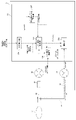
- the exhaust gas analysis system 100 measures the exhaust gas discharged from the engine in the mode operation test (WLTP mode, JC08 mode, etc.) of the vehicle performed by using the chassis test device. It measures the concentration of the target component. More specifically, a constant capacity sampling (CVS) device configured to sample the entire amount of exhaust gas and mix the exhaust gas sampled in total to generate diluted exhaust gas so that the flow rate of the diluted exhaust gas becomes constant. 1.
- the sampling bag M that samples and stores the diluted exhaust gas, and the diluted exhaust gas stored in the diluted exhaust gas sampling bag are analyzed to measure the concentration of the component to be measured in the diluted exhaust gas, and based on the measurement result. It is equipped with an exhaust gas analyzer 2 that calculates the concentration of the component to be measured in the exhaust gas.
- the CVS device 1 joins the main flow path ML through which the exhaust gas discharged from the exhaust pipe 102 of the internal combustion engine 101 flows and the main flow path ML, and at the same time, the dilution gas through which the diluting gas for diluting the exhaust gas flows flows.
- a gas flow path DL and a flow control unit 12 provided downstream from the confluence of the main flow path ML and the diluted gas flow path DL and constantly controlling the flow rate of the diluted exhaust gas diluted with the diluted gas. Is.
- the flow rate control unit 12 is of a critical flow rate Venturi system including a critical flow rate Venturi CFV and a suction pump P.
- a critical flow rate Venturi CFV is provided, but by providing a plurality of critical flow rate Venturi CFVs in parallel and changing the critical flow rate Venturi CFV for flowing diluted exhaust gas by using, for example, an on-off valve or the like, the diluted exhaust gas is provided. It may be configured so that the flow rate of can be changed.
- a part of the diluted exhaust gas is stored in the sampling bag M via the diluted exhaust gas sampling flow path SL in a state where the total flow rate of the exhaust gas and the diluted gas, that is, the flow rate of the diluted exhaust gas is constant. ..
- the diluted exhaust gas (hereinafter, also referred to as sample gas) contained in the sampling bag M is supplied to the exhaust gas analyzer 2, and the exhaust gas analyzer 2 calculates the concentration of the component to be measured in the exhaust gas.
- the exhaust gas analyzer 2 measures the concentration of CO 2 in the sample gas and the first analyzer 21 that measures the concentration of the component to be measured in the sample gas supplied from the sampling bag M.
- the second analyzer 22 is provided with a calculation device 23 for correcting the concentration value of the component to be measured measured by the first analyzer 21.
- the components to be measured are NO x (NO and NO 2 ).
- the first analyzer 21 is specifically a CLD (chemiluminescence method) detector, and in the present embodiment, it is configured to wet-measure NO x in the sample gas.
- the first introduction flow path L1 for introducing the sample gas into the first analyzer 21 is provided with a heating unit (heating block) H for heating the flowing sample gas to a predetermined temperature equal to or higher than the dew point temperature, for example. There is.
- the second analyzer 22 may be any as long as it can measure the CO 2 concentration, for example, an NDIR (non-dispersive infrared absorption method) detector, an FTIR (Fourier transform infrared spectroscopy) detector, or the like. Can be mentioned.
- NDIR non-dispersive infrared absorption method
- FTIR Fastier transform infrared spectroscopy
- the second analyzer 22 is configured to dry-measure the CO 2 concentration in the sample gas.
- the second introduction flow path L2 which is branched from the first introduction flow path L1 and introduces the sample gas into the second analyzer 22, has a water concentration adjusting unit for adjusting the water concentration in the sample gas. D is provided.
- the water concentration adjusting unit D lowers the water concentration contained in the sample gas to a preset set concentration by changing the temperature of the sample gas to keep the water concentration constant.
- the water concentration adjusting unit D uses, for example, a dehumidifier that cools the sample gas introduced into the second analyzer 22 to a temperature below the dew point temperature to dehumidify it.
- the arithmetic unit 23 is a dedicated or general-purpose computer equipped with a CPU, a memory, an AD converter, etc., for correcting the interference influence of other components on NO x , which is a measurement target component. Then, as shown in FIG. 2, the arithmetic unit 23 at least exhibits the functions of the sensitivity coefficient storage unit 231 and the correction unit 232 by the cooperation of the CPU and its peripheral devices according to the analysis program stored in the memory. It is something to do.
- the sensitivity coefficient storage unit 231 is formed in a predetermined area of the memory, and stores the sensitivity coefficient for correcting the influence of other interference components on NO x .
- the sensitivity coefficient data indicating this sensitivity coefficient is stored in the sensitivity coefficient storage unit 231 in advance before the product is shipped or before the product is put into operation.
- this sensitivity coefficient represents the influence of each interference component on the sensitivity of the first analyzer 21, and more specifically, the concentration of each interference component and the sensitivity of the first analyzer 21 at the concentration. It shows the relationship with the relative error of.
- the interference component is a component other than NO x mainly contained in the sample gas, and specifically, CO 2 and H 2 O (hereinafter, also referred to as water).
- the sensitivity coefficient storage unit 231 stores the sensitivity coefficient K CO2 of the first analyzer 21 with respect to the CO 2 concentration and the sensitivity coefficient K H2O of the first analyzer 21 with respect to the water concentration.
- the correction unit 232 was measured by the first analyzer 21 using the concentration of each interference component in the sample gas introduced into the first analyzer 21 and the sensitivity coefficient of the first analyzer 21 for each interference component. It corrects the NO x concentration in the sample gas.
- the correction unit 232 uses the CO 2 concentration and the water concentration in the sample gas introduced into the first analyzer 21 and the sensitivity coefficients K CO2 and K H2O to calculate the following equation (1) or an equivalent thereof. Corrects the NO x concentration measured by the first analyzer 21.
- NO x_a NO x concentration before correction (NO x concentration value measured by the first analyzer 21) [ppm]
- NO x_b Corrected NO x concentration [ppm]
- CO 2 The concentration of CO 2 in the sample gas introduced into the first analyzer 21, where the wet measurement value [ppm] CH2O : Moisture concentration in the sample gas introduced into the first analyzer 21 [ppm] Is.
- the arithmetic apparatus 23 is used to calculate the water concentration in the sample gas introduced into the first analyzer 21 without using the water concentration meter. It further has functions as an input receiving unit 230, a water-coal ratio storage unit 233, a CO 2 concentration conversion unit 234, and a water concentration estimation unit 235.
- the input receiving unit 230 receives input of information regarding the fuel to be used (for example, fuel type, water-coal ratio, etc.), and outputs this to the CO 2 concentration conversion unit 234 and the water concentration estimation unit 235.
- the input receiving unit 230 of the present embodiment receives input of information regarding the fuel type to be used. It should be noted that these information are input by the user using a predetermined input means such as a mouse or a keyboard.
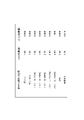
- the water-coal ratio storage unit 233 is formed in a predetermined area of the memory, and stores the water-coal ratio, which is the ratio of hydrogen and carbon constituting the fuel used in the internal combustion engine, in association with the type of fuel. Is.
- the water-coal ratio storage unit 233 of the present embodiment stores water-coal ratio data indicating the water-coal ratios corresponding to a plurality of types of fuels in advance before the product is shipped or before the product is put into operation. This water-coal ratio data may be stored in a tabular format such as a look-up table.
- the water-coal ratio of each fuel shown by this water-coal ratio data is the number of hydrogen atoms (H) with respect to the number of carbon atoms (C) constituting each fuel.
- the CO 2 concentration conversion unit 234 calculates the wet CO 2 concentration obtained by converting the CO 2 concentration dryly measured by the second analyzer 22 into the wet measurement value. Specifically, this CO 2 concentration conversion unit 234 uses the CO 2 concentration dryly measured by the second analyzer 22 and the water coal ratio stored in the water coal ratio storage unit 233 to use the following equation (2) or. The wet CO 2 concentration is calculated by performing an operation equivalent to this.
- the CO 2 concentration conversion unit 234 is configured to acquire the water-coal ratio of the fuel used from the water-coal ratio storage unit 233 based on the information regarding the fuel type received from the input reception unit 230. ..
- CO 2 (wet) Wet CO 2 concentration [ppm]
- CO 2 (dry) CO 2 concentration [ppm] measured dry by the second analyzer 22.
- F H2O Water-coal ratio of the fuel used.
- the water concentration estimation unit 235 estimates the water concentration in the sample gas introduced into the first analyzer 21 (hereinafter, this estimated concentration is also referred to as an estimated water concentration). Specifically, this water concentration estimation unit 235 uses the CO 2 concentration measured by the second analyzer 22 and the water coal ratio stored by the water-coal ratio storage unit 233 to use the following equation (3) or this. The estimated water concentration is calculated by performing an equivalent calculation.
- the water concentration estimation unit 235 is configured to acquire the water-coal ratio of the fuel used from the water-coal ratio storage unit 233 based on the information regarding the fuel type received from the input reception unit 230.
- CH2O (esti) Estimated water concentration [ppm]
- CO 2 (dry) CO 2 concentration [ppm] measured dry by the second analyzer 22.
- F H2O Water-coal ratio of the fuel used.
- the above equations (2) and (3) are the following equations (4) showing the relationship between the water-coal ratio of the fuel, the water concentration in the sample gas obtained by burning the fuel, and the CO 2 concentration.
- the following equation (5) which converts the CO 2 concentration, which is a dry measurement value, into a wet measurement value based on the water concentration, and is derived.
- the correction unit 232 uses the estimated water concentration calculated by the water concentration estimation unit 235 and the wet CO 2 concentration calculated by the CO 2 concentration conversion unit 234 to obtain the NO x concentration measured by the first analyzer 21. to correct. That is, the correction unit 232 corrects the NO x concentration by using the estimated water concentration CH2O (esti) as the water concentration in the formula (1) and the wet CO 2 concentration CO 2 (wet) as the CO 2 concentration.
- the user first inputs information (fuel type) regarding the fuel used in the vehicle test (step S11). Then, the sample gas contained in the sampling bag M is analyzed by the first analyzer 21 and the second analyzer 22, and the NO x concentration and the CO 2 concentration (dry measured value) in the sample gas are measured (step S12). ). The water concentration estimation unit 235 was introduced into the first analyzer 21 based on the CO 2 concentration (dry measured value) measured by the second analyzer 22 and the water-coal ratio corresponding to the input fuel type. Calculate the estimated water concentration contained in the sample gas.
- the CO 2 concentration conversion unit converts the dry measured value into a wet measured value based on the CO 2 concentration (dry measured value) measured by the second analyzer 22 and the water and coal ratio corresponding to the input fuel type.
- the converted CO 2 concentration (wet) is calculated (step S13).
- the correction unit 232 corrects the NO x concentration calculated by the first analyzer 21 based on the calculated estimated water concentration, the CO 2 concentration (wet), and the sensitivity coefficient (step S14).
- the water concentration estimation unit that theoretically estimates the water concentration in the exhaust gas by using the CO 2 concentration in the exhaust gas and the water-coal ratio of the fuel. Since the 235 is provided, it is possible to correct the effect of water on the concentration of NO x measured by the CLD detector 21 without directly measuring the water concentration using a water concentration meter.
- the present invention is not limited to the above embodiment.
- both the first analyzer 21 and the second analyzer 22 may be configured to perform wet measurement.
- the exhaust gas analyzer 2 does not have to have a function as a CO 2 concentration conversion unit 234.
- the water concentration estimation unit 235 uses the CO 2 concentration measured by the second analyzer 22 and the water coal ratio stored by the water-coal ratio storage unit 233 to use the following equation (6) or equivalent. It may be configured to calculate the estimated water concentration by performing various calculations.
- CH2O (esti) Estimated water concentration [ppm]
- CO 2 (wet) CO 2 concentration [ppm] measured wet by the second analyzer 22.
- F H2O Water-coal ratio of the fuel used.
- the correction unit 232 uses the estimated water concentration calculated by the water concentration estimation unit 235 and the CO 2 concentration wet-measured by the second analyzer 22 to measure NO x by the first analyzer 21. Correct the density.
- the input receiving unit 230 of the above embodiment accepts the input of information regarding the fuel type, but in other embodiments, the input receiving unit 230 accepts the input of information regarding the water-coal ratio (H / C, F H2O ) of the fuel. It may be configured in. In this case, when the input receiving unit 230 receives the information regarding the water-coal ratio, it stores the information in the water-coal ratio storage unit 233, and the CO 2 concentration conversion unit 234 and the water concentration estimation unit 235 are in the water-coal ratio storage unit 233. The above calculation may be performed with reference to the water-coal ratio stored in.
- the first analyzer 21 is a CLD detector, but a detector using another principle such as an NDIR detector, a FID detector, an FTIR detector, a QCL-IR detector, etc. may be used. ..
- the component to be measured is NO x
- the measurement target component is not limited to this, and other components such as carbon compounds such as CO, HC and THC and sulfur compounds such as SO 2 , H2 S are used. May be.
- the exhaust gas analysis system 100 samples and dilutes the entire amount of exhaust gas, but the exhaust gas analysis system 100 is not limited to this. In another embodiment, a part of the exhaust gas may be sampled and diluted.
- the exhaust gas analyzer 2 of the above-described embodiment analyzes the diluted exhaust gas obtained by diluting the exhaust gas, but the present invention is not limited to this.
- the exhaust gas analyzer 2 of another embodiment may be configured to analyze the undiluted exhaust gas itself.
- the exhaust gas analysis system 100 measures the components to be measured in the exhaust gas discharged in the test using the chassis test device, but the present invention is not limited to this.
- the component to be measured in the exhaust gas emitted in the test using a drive test device such as an engine test device or a power train may be measured.
- the exhaust gas analysis system 100 measures the components to be measured in the exhaust gas emitted from an internal combustion engine such as an engine, but the present invention is not limited to this.
- the component to be measured in the exhaust gas emitted from an external combustion engine such as a thermal power plant, a factory, or the like may be measured.
- the exhaust gas analysis system 100 of another embodiment measures at least the H2O concentration and the CO2 concentration contained in the atmosphere (hereinafter, also referred to as the test atmosphere) in the test environment (for example, the vehicle test room) where the vehicle test is performed.
- a gas sensor (not shown) is provided, and the exhaust gas analyzer 2 acquires information (atmospheric gas information) regarding the measured H2O concentration and CO2 concentration in the test atmosphere as shown in FIG. It may be configured to correct the concentration of the component to be measured by taking into account the atmospheric gas information.
- the arithmetic unit 23 may further exert its functions as the fuel composition storage unit 236 and the partial pressure correction coefficient calculation unit (calculation unit in the claims) 237.
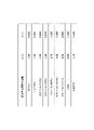
- the fuel composition storage unit 236 stores information on the composition of the fuel used in the internal combustion engine (also simply referred to as composition information) in association with the type of fuel. Specifically, as shown in the table of FIG. 7, this composition information is the number of each element in the chemical formula of each fuel normalized by the number of elements C (here, the number n of H elements and the number m of O elements). Is shown.
- the fuel composition storage unit 236 stores fuel composition data indicating the composition of fuels corresponding to a plurality of types of fuels in advance before the product is shipped or before the product is put into operation. This fuel composition data may be stored in a tabular format such as a look-up table.
- the partial pressure correction coefficient calculation unit 237 corrects the measured values of various gas concentrations measured by using an analyzer or a sensor based on the partial pressure (also simply referred to as partial pressure correction). It is to be calculated.
- the partial pressure correction coefficient calculation unit 237 of the present embodiment measures the first partial pressure correction coefficient ⁇ for dividing the CO 2 concentration in the sample gas measured by the second analyzer 22 and the water concentration meter.
- the second partial pressure correction coefficient ⁇ for dividing the H 2 O concentration in the test atmosphere is calculated.
- the partial pressure correction coefficient is the ratio of the partial pressure of the gas to be corrected in the sample gas to the pressure of the test atmosphere (specifically, the atmospheric pressure), and is the first partial pressure correction coefficient ⁇ and the second partial pressure correction coefficient ⁇ . Is expressed by the following equations (7) and (8), respectively.
- ⁇ Partial pressure of CO 2 in sample gas / atmospheric pressure (7)
- ⁇ Partial pressure of H 2 O in sample gas / atmospheric pressure (8)
- This "partial pressure of CO 2 in the sample gas” means “partial pressure derived from CO 2 existing in the test atmosphere” and “partial pressure derived from CO 2 generated by combustion of fuel” in the sample gas. Means the sum of. The same applies to "partial pressure of H2O in sample gas".
- the partial pressure correction coefficient calculation unit 237 has information on the fuel type received by the input reception unit 230, composition information stored by the fuel composition storage unit 236, and fuel in consideration of the gas component in the atmosphere (the composition thereof is CH).
- the partial pressures of CO 2 and H 2 O in the sample gas are calculated based on at least the complete combustion formula (9) of ( n O m ), and the partial pressure correction coefficients ⁇ and ⁇ are calculated.
- CH n O m Fuel, H 2 O (air) : H 2 O component in the test atmosphere, CO 2 (air) : CO 2 component in the test atmosphere, CO 2 (c Cincinnatimb) : CO 2 component produced by combustion H 2 O (c Brightonmb) : H 2 O component produced by combustion.
- the CO 2 concentration conversion unit 234 calculates the partial pressure correction coefficient in addition to the CO 2 concentration dryly measured by the second analyzer 22 and the water coal ratio stored by the water and coal ratio storage unit 233.
- the wet CO 2 concentration may be calculated by further using the first partial pressure correction coefficient ⁇ calculated by the unit 237 and performing the following equation (10) or an operation equivalent thereto.
- CO 2 (wet) Wet CO 2 concentration [ppm]
- CO 2 (dry) CO 2 concentration [ppm] measured dry by the second analyzer 22.
- F H2O Water-coal ratio of fuel used
- ⁇ The first partial pressure correction coefficient.
- the water concentration estimation unit 235 further measures the CO 2 concentration measured by the second analyzer 22 and the water coal ratio stored by the water coal ratio storage unit 233, as well as the measured H in the test atmosphere. 2 Using the O concentration and the first partial pressure correction coefficient ⁇ and the second partial pressure correction coefficient ⁇ calculated by the partial pressure correction coefficient calculation unit 237, the following equation (11) or an equivalent calculation is performed.
- the estimated water concentration may be calculated by.
- CH2O (esti) Estimated water concentration [ppm], CO 2 (dry) : CO 2 concentration [ppm] measured dry by the second analyzer 22.
- F H2O Water-coal ratio of fuel used, H: H 2 O concentration [ppm] in the test atmosphere, ⁇ : 1st partial pressure correction coefficient, ⁇ : The second partial pressure correction coefficient.
- the correction unit 232 may correct the NO x concentration in the sample gas measured by the first analyzer 21 by using the wet CO 2 concentration and the estimated water concentration calculated in this way.
- the exhaust gas analyzer 2 acquires information on the EGR rate from the ECU of the test vehicle and minutes.
- the pressure correction coefficient calculation unit 237 may calculate the first pressure division correction coefficient ⁇ and the second pressure division correction coefficient ⁇ by using the acquired information on the EGR rate.
- the exhaust gas analyzer 2 of the above-described embodiment has functions as a sensitivity coefficient storage unit 231, a water-coal ratio storage unit 233, and a fuel composition storage unit 236, but the present invention is not limited to this.
- the exhaust gas analyzer 2 of the other embodiment does not have to have a function as a storage unit as shown in FIG.
- the input receiving unit 230 receives the input of information on the sensitivity coefficient, the water-coal ratio, and the fuel composition, and inputs these information to the correction unit 232, the CO 2 concentration conversion unit 234, the water concentration estimation unit 235, and the partial pressure correction coefficient. It may be configured to output to the calculation unit 237.
- the exhaust gas analyzer of the present invention it is possible to correct the influence of water on the component to be measured in the exhaust gas without using a water concentration meter.
Landscapes
- Chemical & Material Sciences (AREA)
- Physics & Mathematics (AREA)
- Health & Medical Sciences (AREA)
- Life Sciences & Earth Sciences (AREA)
- General Physics & Mathematics (AREA)
- Immunology (AREA)
- Pathology (AREA)
- Analytical Chemistry (AREA)
- Biochemistry (AREA)
- General Health & Medical Sciences (AREA)
- Engineering & Computer Science (AREA)
- Biomedical Technology (AREA)
- Chemical Kinetics & Catalysis (AREA)
- Plasma & Fusion (AREA)
- Molecular Biology (AREA)
- Spectroscopy & Molecular Physics (AREA)
- Combustion & Propulsion (AREA)
- Food Science & Technology (AREA)
- Medicinal Chemistry (AREA)
- Investigating Or Analysing Materials By Optical Means (AREA)
- Sampling And Sample Adjustment (AREA)
- Investigating Or Analyzing Non-Biological Materials By The Use Of Chemical Means (AREA)
Abstract
L'invention concerne un dispositif d'analyse de gaz d'échappement (2) pour analyser un gaz d'échappement produit par combustion d'un combustible, le dispositif comprenant : un premier analyseur (21) qui mesure la concentration d'un composant à mesurer dans le gaz d'échappement ; un second analyseur (22) qui mesure la concentration de CO2 dans le gaz d'échappement ; une unité de stockage (233) qui stocke un rapport hydrogène/carbone qui est le rapport de l'hydrogène au carbone constituant le combustible ou une unité de réception d'entrée (230) qui reçoit une entrée du rapport hydrogène/carbone ; une unité d'estimation de la concentration d'eau (235) qui estime la concentration d'eau dans le gaz d'échappement sur la base de la concentration de CO2 mesurée et du rapport hydrogène/carbone du combustible ; et une unité de correction (232) qui corrige la concentration mesurée du composant en train d'être mesuré sur la base de la concentration d'eau estimée.
Priority Applications (4)
| Application Number | Priority Date | Filing Date | Title |
|---|---|---|---|
| US18/029,911 US20230366827A1 (en) | 2020-10-02 | 2021-09-22 | Exhaust gas analysis device, exhaust gas analysis method, and program storage medium for exhaust gas analysis device |
| JP2022553867A JPWO2022071066A1 (fr) | 2020-10-02 | 2021-09-22 | |
| EP21875368.9A EP4224138A1 (fr) | 2020-10-02 | 2021-09-22 | Dispositif d'analyse de gaz d'échappement, procédé d'analyse de gaz d'échappement et support de stockage de programme pour dispositif d'analyse de gaz d'échappement |
| CN202180066838.9A CN116235034A (zh) | 2020-10-02 | 2021-09-22 | 排气分析装置、排气分析方法及排气分析装置用程序存储介质 |
Applications Claiming Priority (4)
| Application Number | Priority Date | Filing Date | Title |
|---|---|---|---|
| JP2020167674 | 2020-10-02 | ||
| JP2020-167674 | 2020-10-02 | ||
| JP2020185255 | 2020-11-05 | ||
| JP2020-185255 | 2020-11-05 |
Publications (1)
| Publication Number | Publication Date |
|---|---|
| WO2022071066A1 true WO2022071066A1 (fr) | 2022-04-07 |
Family
ID=80950248
Family Applications (1)
| Application Number | Title | Priority Date | Filing Date |
|---|---|---|---|
| PCT/JP2021/034823 WO2022071066A1 (fr) | 2020-10-02 | 2021-09-22 | Dispositif d'analyse de gaz d'échappement, procédé d'analyse de gaz d'échappement et support de stockage de programme pour dispositif d'analyse de gaz d'échappement |
Country Status (5)
| Country | Link |
|---|---|
| US (1) | US20230366827A1 (fr) |
| EP (1) | EP4224138A1 (fr) |
| JP (1) | JPWO2022071066A1 (fr) |
| CN (1) | CN116235034A (fr) |
| WO (1) | WO2022071066A1 (fr) |
Citations (7)
| Publication number | Priority date | Publication date | Assignee | Title |
|---|---|---|---|---|
| JPH10267885A (ja) * | 1997-03-21 | 1998-10-09 | Ngk Spark Plug Co Ltd | ガスセンサの補正方法 |
| JPH11230869A (ja) * | 1998-02-13 | 1999-08-27 | Horiba Ltd | 排気ガス分析装置およびその装置を用いたガストレース法によるモーダルマス解析方法 |
| JP2001099781A (ja) * | 1999-09-29 | 2001-04-13 | Horiba Ltd | 赤外吸収法によるガス分析における共存ガス影響の補正方法 |
| JP2006275801A (ja) * | 2005-03-29 | 2006-10-12 | Horiba Ltd | 排気ガス成分分析装置 |
| US7414726B1 (en) * | 2007-10-31 | 2008-08-19 | Bambeck Robert J | Gas analyzer systems and methods |
| JP2010223702A (ja) * | 2009-03-23 | 2010-10-07 | Toyota Motor Corp | 排気ガス分析装置 |
| JP2014174054A (ja) | 2013-03-11 | 2014-09-22 | Horiba Ltd | 排ガス分析装置 |
-
2021
- 2021-09-22 EP EP21875368.9A patent/EP4224138A1/fr active Pending
- 2021-09-22 US US18/029,911 patent/US20230366827A1/en active Pending
- 2021-09-22 JP JP2022553867A patent/JPWO2022071066A1/ja active Pending
- 2021-09-22 WO PCT/JP2021/034823 patent/WO2022071066A1/fr unknown
- 2021-09-22 CN CN202180066838.9A patent/CN116235034A/zh active Pending
Patent Citations (7)
| Publication number | Priority date | Publication date | Assignee | Title |
|---|---|---|---|---|
| JPH10267885A (ja) * | 1997-03-21 | 1998-10-09 | Ngk Spark Plug Co Ltd | ガスセンサの補正方法 |
| JPH11230869A (ja) * | 1998-02-13 | 1999-08-27 | Horiba Ltd | 排気ガス分析装置およびその装置を用いたガストレース法によるモーダルマス解析方法 |
| JP2001099781A (ja) * | 1999-09-29 | 2001-04-13 | Horiba Ltd | 赤外吸収法によるガス分析における共存ガス影響の補正方法 |
| JP2006275801A (ja) * | 2005-03-29 | 2006-10-12 | Horiba Ltd | 排気ガス成分分析装置 |
| US7414726B1 (en) * | 2007-10-31 | 2008-08-19 | Bambeck Robert J | Gas analyzer systems and methods |
| JP2010223702A (ja) * | 2009-03-23 | 2010-10-07 | Toyota Motor Corp | 排気ガス分析装置 |
| JP2014174054A (ja) | 2013-03-11 | 2014-09-22 | Horiba Ltd | 排ガス分析装置 |
Also Published As
| Publication number | Publication date |
|---|---|
| CN116235034A (zh) | 2023-06-06 |
| EP4224138A1 (fr) | 2023-08-09 |
| US20230366827A1 (en) | 2023-11-16 |
| JPWO2022071066A1 (fr) | 2022-04-07 |
Similar Documents
| Publication | Publication Date | Title |
|---|---|---|
| EP1914545B1 (fr) | Analyseur de gaz d'échappement montable sur un véhicule | |
| US6085582A (en) | Vehicle mass emission measurement | |
| US6387706B1 (en) | Vehicle mass emission measurement | |
| US10955398B2 (en) | Calibration method for gas analysis apparatus, gas analysis system, and pressure varying device | |
| JP4413160B2 (ja) | 排気ガス成分分析装置 | |
| US11168629B2 (en) | Exhaust gas analysis apparatus, exhaust gas analysis method, and correction expression creation method | |
| CN109425489B (zh) | 排气分析装置、排气分析方法和存储介质 | |
| JP6967387B2 (ja) | ガス分析装置、ガス分析装置用プログラム、及びガス分析方法 | |
| JP4550645B2 (ja) | 車両搭載型排気ガス分析装置 | |
| JP6093607B2 (ja) | 排ガス分析装置 | |
| WO2018105169A1 (fr) | Dispositif et procédé d'analyse de gaz | |
| WO2022071066A1 (fr) | Dispositif d'analyse de gaz d'échappement, procédé d'analyse de gaz d'échappement et support de stockage de programme pour dispositif d'analyse de gaz d'échappement | |
| JP2010139281A (ja) | 排気ガス測定装置 | |
| WO2023127262A1 (fr) | Dispositif d'apprentissage automatique, dispositif d'analyse de gaz d'échappement, procédé d'apprentissage automatique, procédé d'analyse de gaz d'échappement, programme d'apprentissage automatique et programme d'analyse de gaz d'échappement | |
| WO2022211111A1 (fr) | Système de mesure de la quantité d'hydrogène consommé | |
| JP4205821B2 (ja) | 赤外吸収法によるガス分析における共存ガス影響の補正方法及びガス分析計 | |
| Austin et al. | Improving the calculation of exhaust gas dilution during constant volume sampling | |
| Butler et al. | A system for on-line measurement of multicomponent emissions and engine operating parameters | |
| Pham et al. | Evaluation of partial flow dilution systems for very low PM mass measurements | |
| Hoard et al. | NOx Measurement Errors in Ammonia-Containing Exhaust | |
| JP2001159587A (ja) | ガス分析装置 | |
| CN117388204B (zh) | 一氧化氮气体分析系统、方法及计算机可读存储介质 | |
| JP3220602B2 (ja) | 多成分同時連続分析方法 | |
| WO2019012773A1 (fr) | Dispositif d'analyse de gaz, programme pour dispositif d'analyse de gaz et procédé d'analyse de gaz | |
| JP2024020048A (ja) | 車両搭載型の排ガス分析装置、排ガス分析方法、及び、排ガス分析装置用プログラム |
Legal Events
| Date | Code | Title | Description |
|---|---|---|---|
| 121 | Ep: the epo has been informed by wipo that ep was designated in this application |
Ref document number: 21875368 Country of ref document: EP Kind code of ref document: A1 |
|
| ENP | Entry into the national phase |
Ref document number: 2022553867 Country of ref document: JP Kind code of ref document: A |
|
| NENP | Non-entry into the national phase |
Ref country code: DE |
|
| ENP | Entry into the national phase |
Ref document number: 2021875368 Country of ref document: EP Effective date: 20230502 |