WO2022071029A1 - ステータおよびモータ - Google Patents
ステータおよびモータ Download PDFInfo
- Publication number
- WO2022071029A1 WO2022071029A1 PCT/JP2021/034609 JP2021034609W WO2022071029A1 WO 2022071029 A1 WO2022071029 A1 WO 2022071029A1 JP 2021034609 W JP2021034609 W JP 2021034609W WO 2022071029 A1 WO2022071029 A1 WO 2022071029A1
- Authority
- WO
- WIPO (PCT)
- Prior art keywords
- conductor
- circumferential direction
- portions
- phase
- connecting body
- Prior art date
- Legal status (The legal status is an assumption and is not a legal conclusion. Google has not performed a legal analysis and makes no representation as to the accuracy of the status listed.)
- Ceased
Links
Images






Classifications
-
- H—ELECTRICITY
- H02—GENERATION; CONVERSION OR DISTRIBUTION OF ELECTRIC POWER
- H02K—DYNAMO-ELECTRIC MACHINES
- H02K1/00—Details of the magnetic circuit
- H02K1/06—Details of the magnetic circuit characterised by the shape, form or construction
- H02K1/12—Stationary parts of the magnetic circuit
- H02K1/16—Stator cores with slots for windings
-
- H—ELECTRICITY
- H02—GENERATION; CONVERSION OR DISTRIBUTION OF ELECTRIC POWER
- H02K—DYNAMO-ELECTRIC MACHINES
- H02K3/00—Details of windings
- H02K3/04—Windings characterised by the conductor shape, form or construction, e.g. with bar conductors
- H02K3/12—Windings characterised by the conductor shape, form or construction, e.g. with bar conductors arranged in slots
-
- H—ELECTRICITY
- H02—GENERATION; CONVERSION OR DISTRIBUTION OF ELECTRIC POWER
- H02K—DYNAMO-ELECTRIC MACHINES
- H02K3/00—Details of windings
- H02K3/04—Windings characterised by the conductor shape, form or construction, e.g. with bar conductors
- H02K3/28—Layout of windings or of connections between windings
-
- H—ELECTRICITY
- H02—GENERATION; CONVERSION OR DISTRIBUTION OF ELECTRIC POWER
- H02K—DYNAMO-ELECTRIC MACHINES
- H02K3/00—Details of windings
- H02K3/46—Fastening of windings on the stator or rotor structure
- H02K3/50—Fastening of winding heads, equalising connectors, or connections thereto
-
- H—ELECTRICITY
- H02—GENERATION; CONVERSION OR DISTRIBUTION OF ELECTRIC POWER
- H02K—DYNAMO-ELECTRIC MACHINES
- H02K2203/00—Specific aspects not provided for in the other groups of this subclass relating to the windings
- H02K2203/09—Machines characterised by wiring elements other than wires, e.g. bus rings, for connecting the winding terminations
Definitions
- the present invention relates to a stator and a motor. This application claims priority based on Japanese Patent Application No. 2020-165709 filed in Japan on September 30, 2020, the contents of which are incorporated herein by reference.
- one of the objects of the present invention is to provide a stator and a motor that can be easily connected to a bus bar.
- stator of the present invention includes a stator core which is annular around the central axis and is provided with a plurality of slots arranged in the circumferential direction, and a plurality of phase phase coil portions mounted on the stator core.
- the phase coil portion has a conductor connecting body in which a plurality of conductors are connected in series.
- the conductor connecting body connects a plurality of straight portions passing through the slot, a plurality of bending portions passing the straight portions on one side in the axial direction of the stator core, and the conductors on the other side in the axial direction of the stator core. It has a plurality of connecting portions and a plurality of connecting portions.
- One of the slots is provided with even layers arranged in the radial direction.
- the conductor connecting body orbits the conductor connecting body by alternately passing the straight line portions arranged in the circumferential direction through the layer of the M layer and the layer of the M + 1 layer, where M is an odd natural number.
- the conductor connecting body includes a first terminal portion, a first portion that is wave-wound from the first terminal portion to one side in the circumferential direction, and a folded portion connected to one end portion in the circumferential direction of the first portion. It has a second portion that is wave-wound from the folded portion to the other side in the circumferential direction, and a second end portion that is connected to the end portion of the second portion on the other side in the circumferential direction.
- the first portion of the plurality of in-phase conductor connectors is sequentially arranged in the slots arranged one by one on one side in the circumferential direction.
- the second portion of the plurality of in-phase conductor connectors is sequentially arranged in the slots arranged one by one on the other side in the circumferential direction.
- the first terminal portion and the second terminal portion extend from the outermost layer.
- One said phase coil portion has at least two or more said conductor connectors.
- the first end portions of the two or more conductor connectors of one phase coil portion are electrically connected to each other.
- the second end portions of the two or more conductor connectors of one phase coil portion are electrically connected to each other.
- One aspect of the motor of the present invention includes the above-mentioned stator and a rotor facing the stator in the radial direction.
- FIG. 1 is a schematic cross-sectional view of the motor of one embodiment.
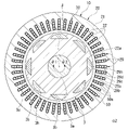
- FIG. 2 is a cross-sectional view of a rotor and a stator according to an embodiment.
- FIG. 3 is a partial cross-sectional view of the stator of one embodiment.
- FIG. 4 is a perspective view of the stator of one embodiment.
- FIG. 5 is a plan view of the stator of one embodiment.
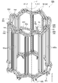
- FIG. 6 is a perspective view of the phase coil portion of one embodiment.
- FIG. 7 is a front view of the terminal conductor of one embodiment.
- FIG. 8 is a front view of the hairpin conductor of one embodiment.
- FIG. 9 is a front view of the interlayer hairpin conductor of one embodiment.
- FIG. 10 is a front view of the first folding conductor of one embodiment.
- the Z-axis direction appropriately shown in each figure is a vertical direction in which the positive side is the "upper side” and the negative side is the “lower side”.
- the central axis J appropriately shown in each figure is a virtual line that is parallel to the Z-axis direction and extends in the vertical direction.
- the axial direction of the central axis J that is, the direction parallel to the vertical direction is simply referred to as "axial direction”
- the upper side is referred to as "axial direction one side”
- the lower side is referred to as "axial direction other side”.
- the radial direction centered on the central axis J may be simply referred to as "diametrical direction”.
- circumferential direction centered on the central axis J is simply called “circumferential direction”
- the clockwise direction when viewed from above is called “one side in the circumferential direction”
- the counterclockwise direction when viewed from above is called “circumferential direction”.
- the other side of the direction is sometimes referred to as "the other side of the direction”.
- FIG. 1 is a schematic cross-sectional view of the motor 1 of the present embodiment.
- the motor 1 of the present embodiment is an inner rotor type motor.
- the center of the motor 1 is the central axis J.
- the rotor 3 can rotate around the central axis J.
- the rotor 3 is arranged radially inside the annular stator 10. That is, the rotor 3 faces the stator 10 in the radial direction.
- the rotor 3 has a shaft 3a, a rotor magnet 3b, and a rotor core 3c.
- the shaft 3a extends in the axial direction along the central axis J.
- the shaft 3a is, for example, a columnar shape extending in the axial direction about the central axis J.
- the shaft 3a is rotatably supported around the central axis J by bearings 5a and 5b.
- the rotor core 3c is configured by laminating electromagnetic steel sheets.
- the rotor core 3c has a tubular shape extending in the axial direction.
- the inner peripheral surface of the rotor core 3c is fixed to the outer peripheral surface of the shaft 3a.
- the rotor core 3c is located between the pair of bearings 5a and 5b in the axial direction.
- the rotor core 3c is provided with a holding hole 3h into which the rotor magnet 3b is inserted and fixed.
- the stator core 20 is an annular shape centered on the central axis J.
- the stator core 20 is made of a plurality of electrical steel sheets laminated along the axial direction.
- the stator core 20 has a cylindrical core back portion 21 centered on the central axis J, and a plurality of teeth portions 22 extending radially inward from the core back portion 21.
- the plurality of teeth portions 22 are arranged at equal intervals in the circumferential direction.
- An umbrella portion 22a is provided at the tip portion on the inner side in the radial direction of the tooth portion 22.
- the umbrella portion 22a projects on both sides in the circumferential direction with respect to the teeth portion 22. That is, the circumferential dimension of the umbrella portion 22a is larger than the circumferential dimension of the teeth portion 22.
- the surface of the umbrella portion 22a facing inward in the radial direction faces the outer peripheral surface of the rotor 3 in the radial direction via a gap.
- the stator coil 30 is mounted on the teeth portion 22.
- a slot 29 is provided between the tooth portions 22 adjacent to each other in the circumferential direction. That is, the stator core 20 is provided with a plurality of slots 29 arranged in the circumferential direction.
- One slot 29 is provided with layers 29a, 29b, 29c, and 29d having four or more even layers (four layers in this embodiment) arranged in the radial direction.
- the four layers are referred to as a first layer 29a, a second layer 29b, a third layer 29c, and a fourth layer 29d, respectively, from the outside to the inside in the radial direction.
- the first layer 29a is the first layer
- the second layer 29b is the second layer
- the third layer 29c is the third layer
- the fourth layer 29d Is the fourth layer.
- the width dimension along the circumferential direction of the slot 29 of the present embodiment is slightly larger than the dimension along the circumferential direction of the conductor 50.
- one conductor 50 is arranged in each of the layers 29a, 29b, 29c, and 29d.
- four conductors 50 are arranged in a row along the radial direction.
- a U-phase bus bar (phase bus bar) 9U is connected to the U-phase coil portion 30U. An alternating current is passed through the U-phase coil portion 30U via the U-phase bus bar 9U.
- a V-phase bus bar (phase bus bar) 9V is connected to the V-phase coil portion 30V. An alternating current is passed through the V-phase coil portion 30V via the V-phase bus bar 9V.
- a W-phase bus bar (phase bus bar) 9W is connected to the W-phase coil portion 30W. An alternating current is passed through the W-phase coil portion 30W via the W-phase bus bar 9W.
- the phases of the alternating currents flowing through the U-phase coil section 30U, the V-phase coil section 30V, and the W-phase coil section 30W are each shifted by 120 °.
- the neutral point bus bar 8 is connected to the U-phase coil portion 30U, the V-phase coil portion 30V, and the W-phase coil portion 30W.
- Neutral point The bus bar 8 constitutes the neutral point of the three-phase circuit.
- FIG. 6 is a perspective view of one phase coil portion 30A of the three-phase phase coil portions 30A.
- the phase coil unit 30A described below may be any of the U-phase coil unit 30U, the V-phase coil unit 30V, and the W-phase coil unit 30W.
- phase coil portion 30A has at least two or more conductor connectors 60.
- the phase coil portion 30A includes two conductor connecting bodies 60.
- the conductor connecting body 60 is configured by connecting a plurality of conductors 50 in series.
- first conductor connecting body 60A when the two conductor connecting bodies 60 are distinguished from each other, one is referred to as a first conductor connecting body 60A and the other is referred to as a second conductor connecting body 60B.
- the conductor 50 is configured by winding a flat wire. Therefore, the space factor of the conductor 50 in the slot 29 can be improved as compared with the case of using the round wire.
- the "flat wire” is a wire rod having a quadrangular cross-sectional shape or a substantially quadrangular cross-sectional shape. As used herein, the term “substantially square” includes a square with rounded corners.
- the conductor 50 in this embodiment has an enamel coating on its surface.
- the stator 10 of the present embodiment can be assembled by inserting a plurality of conductors 50 into the slots 29 of the stator core 20 from the upper side and welding them from the lower side. Therefore, the assembly process can be simplified without requiring a complicated assembly process.
- the terminal conductor 51 has one terminal portion 50c, one linear portion 50a, and one connecting portion 50b.
- the end portion 50c is located at the upper end portion of the end conductor 51.
- the end portion 50c is bent in the circumferential direction with respect to the straight portion 50a.
- the end portion 50c and the connecting portion 50b are bent in opposite directions in the circumferential direction.
- the terminal portion 50c extends from the upper end of the straight line portion 50a to the other side ⁇ 2 in the circumferential direction
- the connecting portion 50b extends from the lower end of the straight line portion 50a to the one side ⁇ 1 in the circumferential direction.
- the hairpin conductor 52 has two straight portions 50a, two connecting portions 50b, and one bent portion 50d.
- the bent portion 50d is arranged at the upper end portion of the hairpin conductor 52.
- the bent portion 50d passes the two straight portions 50a to each other. That is, in the hairpin conductor 52, the two straight portions 50a are connected to each other via the bent portion 50d.
- the two connecting portions 50b are connected to the lower ends of different linear portions 50a.
- the two connecting portions 50b are lined up in the number of slots per pole.
- the number of slots per pole means the number of slots 29 of the stator 10 arranged between one magnetic pole of the rotor 3 in the combination of the rotor 3 and the stator 10.
- the number of slots per pole is calculated by (the total number of slots of the stator 10) / (the number of magnetic poles of the rotor 3).
- the number of magnetic poles of the rotor 3 is 8
- the number of slots of the stator 10 is 48, so that the number of slots per pole is 6.
- the two connecting portions 50b are separated from each other by 6 slots in the circumferential direction.
- the two connecting portions 50b are arranged in the number of slots per pole (6 slots in this embodiment).
- the two connecting portions 50b are bent in opposite directions in the circumferential direction.
- one located on one side ⁇ 1 in the circumferential direction extends from the lower end of the straight portion 50a to ⁇ 1 on one side in the circumferential direction, and the other located on the other side ⁇ 2 in the circumferential direction is circumferentially oriented from the lower end of the straight portion 50a. It extends to the other side ⁇ 2.
- the structure of the interlayer bent portion 50e of the interlayer hairpin conductor 53 is mainly different from that of the hairpin conductor 52.
- the shape of the interlayer bent portion 50e is slightly different from that of the bent portion 50d of the hairpin conductor 52. As shown in FIG. 12, the first conductor connecting body 60A and the second conductor connecting body 60B are each provided with two interlayer hairpin conductors 53.
- the first folded conductor 54 has two straight portions 50a, two connecting portions 50b, and one first folded portion (folded portion) 50f.
- the second folded conductor 55 has two straight portions 50a, two connecting portions 50b, and one second folded portion (folded portion) 50 g.
- the first folded-back portion 50f and the second folded-back portion 50 g are arranged at the upper ends of the first folded-back conductor 54 or the second folded-back conductor 55, respectively.
- the first folded portion 50f and the second folded portion 50g pass the two straight portions 50a to each other. That is, in the first folding conductor 54 and the second folding conductor 55, the two straight portions 50a are connected to each other via the first folding portion 50f or the second folding portion 50g, respectively.
- the two connecting portions 50b are bent to the other side ⁇ 2 in the circumferential direction. That is, in the first folding conductor 54 and the second folding conductor 55, the two connecting portions 50b each extend from the lower end of the straight line portion 50a to the other side ⁇ 2 in the circumferential direction.
- the distances between the two connecting portions 50b are different from each other.
- the two connecting portions 50b are arranged in the number of slots per pole + 1 (7 slots in the present embodiment).
- the two connecting portions 50b are lined up with the number of slots per pole-1 (5 slots in this embodiment). Therefore, the first folded-back portion 50f has a larger crossover amount in the circumferential direction by two slots than the second folded-back portion 50g.
- the first folded portion 50f has a bent portion 50fa that bends from one side ⁇ 1 in the circumferential direction to ⁇ 2 on the other side in the circumferential direction, and two extending portions 50fb and 50fc connected to both ends of the bent portion 50fa.
- the first folded-back portion 50f extends from the slot 29 to one side ⁇ 1 in the circumferential direction at the two extending portions 50fb and 50fc.
- the two extending portions 50fb and 50fc extend in parallel with each other before and after the bent portion 50fa.
- the second folded portion 50 g has a bent portion 50 ga that bends from one side ⁇ 1 in the circumferential direction to ⁇ 2 on the other side in the circumferential direction, and two extending portions 50 gb and 50 gc connected to both ends of the bent portion 50 ga.
- the second folded-back portion 50 g extends from the slot 29 to one side ⁇ 1 in the circumferential direction at the two extended portions 50 gb and 50 gc.
- the two extending portions 50gb and 50gc extend in parallel with each other before and after the bent portion 50ga.
- the first conductor connecting body 60A is provided with one first folding conductor 54.
- the second conductor connecting body 60B is provided with one second folding conductor 55.
- the two terminal conductors 51 are arranged at the ends of both ends of the first conductor connecting body 60A, respectively, and the first folding conductor 54 is substantially in the middle. Is placed.
- the first conductor connecting body 60A has two terminal conductors 51, twelve hairpin conductors 52, two interlayer hairpin conductors 53, and a first folding conductor 54.
- first conductor connecting body 60A one end conductor 51, three hairpin conductors 52, one interlayer hairpin conductor 53, three hairpin conductors 52, a first folding conductor 54, and three hairpins.
- the conductor 52, one interlayer hairpin conductor 53, three hairpin conductors 52, and the other end conductor 51 are connected in this order.
- the first conductor connecting body 60A includes a plurality of (32 pieces) straight portions 50a, and a plurality of (14 pieces) bent portions 50d and 50e passing the straight portions 50a on the upper side (one side in the axial direction) of the stator core 20. It has a plurality of (16) connecting portions 50b for connecting the conductors 50 to each other on the lower side (the other side in the axial direction) of the stator core 20.
- the first conductor connecting body 60A is wave-wound every 6 slots toward ⁇ 1 on one side in the circumferential direction from one end portion 50c to the first folded portion 50f. Further, the first conductor connecting body 60A is wave-wound every 6 slots toward the other side ⁇ 2 in the circumferential direction from the first folded-back portion 50f to the other end portion 50c.
- one end portion 50c connected to any of the compatible bus bars 9U, 9V, and 9W is referred to as an input side end portion (first end portion) 63 and is neutral.
- the other end portion 50c connected to the point bus bar 8 is referred to as a neutral point side end portion (second end portion) 64.
- the region that is wave-wound in the circumferential direction one side ⁇ 1 between the input side end portion 63 and the first folded portion 50f is referred to as a first portion 61.
- the region that is wave-wound on the other side ⁇ 2 in the circumferential direction between the first folded-back portion 50f and the neutral point side end portion 64 is referred to as a second portion 62.
- the circumferential direction one side ⁇ 1 is defined as the forward direction
- the circumferential direction other side ⁇ 2 is defined as the reverse direction
- the first portion 61 can be referred to as a forward direction portion
- the second portion 62 can be referred to as a reverse direction portion.
- the first conductor connecting body 60A has an input side end portion 63, a first portion 61 wave-wound from the input side end portion 63 to one side ⁇ 1 in the circumferential direction, and an end of ⁇ 1 on one side in the circumferential direction of the first part 61.
- the second portion 62 wave-wound from the first folded-back portion 50f to the other side ⁇ 2 in the circumferential direction, and the other side ⁇ 2 in the circumferential direction of the second portion 62. It has a neutral point side end portion 64 to be connected.
- FIG. 13 is a schematic view showing an arrangement in the slot 29 through which the straight line portion 50a of the first portion 61 of the first conductor connecting body 60A passes.
- FIG. 14 is a schematic view showing an arrangement in the slot 29 through which the straight portion 50a of the second portion 62 of the first conductor connecting body 60A passes.
- the first conductor connecting body 60A orbits in the first portion 61 on one side ⁇ 1 in the circumferential direction by two turns.
- the first portion 61 may make two or more laps.
- the first conductor connecting body 60A orbits in the second portion 62 on the other side ⁇ 2 in the circumferential direction by two turns.
- the second portion 62 may orbit the other side ⁇ 2 in the circumferential direction by the same number as the first portion 61.
- the first portion 61 and the second portion 62 of the first conductor connecting body 60A each have an interlayer bending portion 50e at a boundary where the circumference changes.
- the "boundary in which the lap changes” is the boundary between the first lap and the second lap around the central axis J, and the boundary between the Nth lap and the N + 1 lap in the arrangement of the first part 61 and the second part 62.
- Etc. which means a region where the number of laps changes.
- the linear portions 50a arranged in the circumferential direction are alternately arranged in the first layer 29a and the second layer 29b between the input side end portion 63 and the interlayer bending portion 50e. Pass through and go around.
- the first conductor connecting body 60A extends from the second layer 29b to the third layer 29c at the interlayer bending portion 50e of the first portion 61.
- the first conductor connecting body 60A orbits between the interlayer bending portion 50e and the first folded portion 50f by alternately passing straight portions 50a arranged in the circumferential direction through the third layer 29c and the fourth layer 29d. ..
- the straight line portion 50a passes through the same slot 29 on the first and second laps.
- the linear portions 50a arranged in the circumferential direction between the first folded portion 50f and the interlayer bending portion 50e are formed on the third layer 29c and the fourth layer 29d. Pass alternately and go around.
- the first conductor connecting body 60A extends from the third layer 29c to the second layer 29b at the interlayer bending portion 50e of the second portion 62.
- the first conductor connecting body 60A orbits between the interlayer bending portion 50e and the neutral point side end portion 64 by alternately passing straight portions 50a arranged in the circumferential direction through the first layer 29a and the second layer 29b. do.
- the straight line portion 50a passes through the same slot 29 on the first and second laps.
- the second conductor connecting body 60B has substantially the same structure as the first conductor connecting body 60A, but mainly differs in the structure of the folded portion and the position of the slot 29 through which it passes.
- the two end conductors 51 are arranged at the ends of both ends of the second conductor connecting body 60B, respectively, and the second folding conductor 55 is substantially in the middle. Is placed.
- the second conductor connecting body 60B has two terminal conductors 51, twelve hairpin conductors 52, two interlayer hairpin conductors 53, and a second folding conductor 55.
- the conductor 52, one interlayer hairpin conductor 53, three hairpin conductors 52, and the other end conductor 51 are connected in this order.
- the second conductor connecting body 60B includes a plurality of (32 pieces) straight portions 50a, and a plurality of (14 pieces) bent portions 50d and 50e passing the straight portions 50a on the upper side (one side in the axial direction) of the stator core 20. It has a plurality of (16) connecting portions 50b for connecting the conductors 50 to each other on the lower side (the other side in the axial direction) of the stator core 20.
- the second conductor connecting body 60B is 6 toward the circumferential direction ⁇ 1 during the period from the input side end portion 63, which is one end portion 50c, to the second folded portion 50 g (first portion 61). Waves are wound for each slot. Further, the second conductor connecting body 60B has a circumferential direction opposite side ⁇ 2 from the second folded-back portion 50g to the other end portion 50c, which is the neutral point side end portion 64 (second portion 62). It is waved every 6 slots toward.
- the second conductor connecting body 60B has an input side end portion 63, a first portion 61 wave-wound from the input side end portion 63 to one side ⁇ 1 in the circumferential direction, and ⁇ 1 on one side in the circumferential direction of the first part 61.
- It has a neutral point side end portion 64, which is connected to the portion.
- FIG. 15 is a schematic view showing an arrangement in the slot 29 through which the straight line portion 50a of the first portion of the second conductor connecting body 60B passes.
- FIG. 16 is a schematic view showing an arrangement in the slot 29 through which the straight line portion 50a of the second portion of the second conductor connecting body 60B passes.
- the second conductor connecting body 60B orbits in the first portion 61 on one side ⁇ 1 in the circumferential direction by two turns, and in the second portion 62, the same number as the first portion 61 (that is, two turns) on the other side ⁇ 2 in the circumferential direction. Just go around.
- the first portion 61 and the second portion 62 of the second conductor connecting body 60B each have an interlayer bending portion 50e at a boundary where the circumference changes.
- the second conductor connecting body 60B orbits between the input side end portion 63 and the interlayer bending portion 50e by alternately passing the linear portions 50a arranged in the circumferential direction through the first layer 29a and the second layer 29b.
- the second conductor connecting body 60B extends from the second layer 29b to the third layer 29c at the interlayer bending portion 50e of the first portion 61.
- the second conductor connecting body 60B orbits between the interlayer bending portion 50e and the second folded portion 50g by alternately passing straight portions 50a arranged in the circumferential direction through the third layer 29c and the fourth layer 29d. ..
- the straight line portion 50a passes through the same slot 29 on the first and second laps.
- a linear portion 50a arranged in the circumferential direction between the second folded portion 50g and the interlayer bending portion 50e is formed on the third layer 29c and the fourth layer 29d. Pass alternately and go around.
- the second conductor connecting body 60B extends from the third layer 29c to the second layer 29b at the interlayer bending portion 50e of the second portion 62.
- the second conductor connecting body 60B orbits between the interlayer bending portion 50e and the neutral point side end portion 64 by alternately passing straight portions 50a arranged in the circumferential direction through the first layer 29a and the second layer 29b. do.
- the straight line portion 50a passes through the same slot 29 on the first and second laps.
- the conductor connecting body 60 makes two rounds in the first portion 61 and the second portion 62. Therefore, the density of the magnetic flux generated in the stator 10 can be increased as compared with the case where the conductor connecting body 60 makes only one round, and the output of the motor 1 can be increased.
- the conductor connecting body 60 may make two or more turns in the first portion 61 and the second portion 62.
- N is a natural number
- M be an odd natural number (1, 3, 5, ).
- the straight line portions 50a arranged in the circumferential direction are combined with the M layer (for example, the first layer) layer and the M + 1st layer (for example, the second layer). Pass alternately between them and make one lap.
- the conductor connecting body 60 changes from the M + 1 layer (for example, the second layer) to the M + second layer (for example, the third layer) at the boundary between the Nth lap (for example, the first lap) and the N + 1th lap (for example, the second lap). It has an interlayer bent portion 50e extending across the layer. According to this embodiment, the phase coil portion 30A can be simply configured even when the conductor connecting body 60 is used for 2 weeks or more.
- the plurality of linear portions 50a have the number of slots per pole (6 slots in the present embodiment). Line up in the circumferential direction. That is, the first conductor connecting body 60A is wound around the stator core 20 by so-called all-node winding. In the all-node winding, the conductor 50 having the same phase is arranged in one slot 29, it is easy to secure the insulation between the U phase, the V phase, and the W phase, and the performance of the motor 1 can be stabilized.
- the conductor connecting body 60 has a configuration in which the conductors 50 are laminated in the radial direction in the first portion 61 and the second portion 62. As a result, the density of the magnetic flux generated by the current flowing through each conductor 50 can be increased according to the number of laps of the conductor connector 60.
- the first portion 61 of the first conductor connecting body 60A and the first part 61 of the second conductor connecting body 60B pass through different slots 29 from each other.
- the second portion 62 of the first conductor coupling 60A and the second portion 62 of the second conductor coupling 60B pass through different slots 29 from each other.
- the slot 29 through which the straight line portion 50a passes is displaced by one slot from the first portion 61 of the first conductor connecting body 60A to ⁇ 1 on one side in the circumferential direction. ..
- the slot 29 through which the straight line portion 50a passes is only one slot on the other side ⁇ 2 in the circumferential direction with respect to the second portion 62 of the first conductor connecting body 60A. It is out of alignment. That is, the first portion 61 of the plurality of conductor connectors 60 having the same phase is sequentially arranged in the slots 29 arranged one by one on one side ⁇ 1 in the circumferential direction. Further, the second portion 62 of the plurality of conductor connecting bodies 60 having the same phase is sequentially arranged in the slots 29 arranged one by one on the other side ⁇ 2 in the circumferential direction.
- the first portion 61 of the first conductor connecting body 60A and the second part 62 of the second conductor connecting body 60B are arranged in the same slot. Only the conductor connecting body 60 having the same phase passes through one slot 29, and the insulation between the plurality of phase coil portions 30A can be easily ensured.
- the two end portions 50c extend from slots 29 separated by the number of slots per pole + 1 (7 slots) in the circumferential direction. Get out.
- the neutral point side end portion 64 located on one side ⁇ 1 in the circumferential direction is compared with the input side end portion 63 located on the other side ⁇ 2 in the circumferential direction. , Extends one slot longer on one side ⁇ 1 in the circumferential direction. Therefore, the two end portions 50c of the first conductor connecting body 60A are arranged apart by the number of slots per pole (6 slots) in the circumferential direction.
- the two end portions 50c (input side end portion 63 and neutral point side end portion 64) are separated from the slot 29 by the number of slots per pole-1 (5 slots) in the circumferential direction. Extend out.
- the input side end portion 63 located on the other side ⁇ 2 in the circumferential direction is compared with the neutral point side end portion 64 located on the one side ⁇ 1 in the circumferential direction. , Extends one slot longer on one side ⁇ 1 in the circumferential direction. Therefore, the two end portions 50c of the second conductor connecting body 60B are arranged apart by the number of slots per pole (6 slots) in the circumferential direction.
- the input side end portion 63 of the in-phase conductor coupling 60 and the neutral point-side end portion 64 of the in-phase conductor coupling 60 are arranged apart by the number of slots for each pole in the circumferential direction. Therefore, the input side end portions 63 and the neutral point side end portions 64 of the plurality of conductor connecting bodies 60 (first conductor connecting body 60A and second conductor connecting body 60B) can be arranged so as to be overlapped with each other.
- the input-side end portions 63 of the in-phase conductor connecting bodies 60 are arranged side by side in the radial direction and are connected to each other.
- the input-side end 63 of the in-phase conductor connector 60 is both connected to a compatible bus bar (U-phase bus bar 9U, V-phase bus bar 9V, or W-phase bus bar 9W).
- the neutral point side end portions 64 of the in-phase conductor connecting bodies 60 are arranged side by side in the radial direction and are connected to each other. Further, the neutral point side end portion 64 of the in-phase conductor connecting body 60 is both connected to the neutral point bus bar 8.
- the input side end portions 63 of the two or more conductor connecting bodies 60 of one phase coil portion 30A are electrically connected to each other.
- the neutral point side end portions 64 of the two or more conductor connecting bodies 60 of one phase coil portion 30A are electrically connected to each other.
- the plurality of conductor connectors 60 of one phase coil portion 30A are connected in parallel to each other.
- At least one of the neutral point bus bar 8 and the compatible bus bars 9U, 9V, and 9W is located at the radial position of the folded portion 50f, 50 g, the radial position of the folded portion 50f, 50 g, the input side end portion 63, and the neutral point. It is located between the radial position of the side end portion 64. That is, when viewed from the axial direction, at least one of the neutral point bus bar 8 and the compatible bus bars 9U, 9V, 9W is arranged between the inner edge and the outer edge of the coil end of the stator coil 30. Therefore, it is possible to prevent at least one of the neutral point bus bar 8 and the compatible bus bars 9U, 9V, and 9W from projecting to both sides in the radial direction with respect to the stator coil 30.
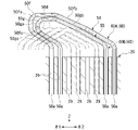
- FIG. 17 is a schematic view showing a first folded-back portion 50f and a second folded-back portion 50 g.
- the first conductor connecting body 60A folds the wave winding direction from the circumferential direction ⁇ 1 to the circumferential direction other side ⁇ 2 at the first folded portion 50f.
- the second conductor connecting body 60B folds the wave winding direction from one side ⁇ 1 in the circumferential direction to ⁇ 2 on the other side in the circumferential direction at the second folded portion 50g.
- the two slots 29 extending from the first folded portion 50f are separated by 7 slots (that is, the number of slots per pole + 1).
- the two slots 29 extending from the second folded portion 50 g are separated by 5 slots (that is, the number of slots per pole-1).
- the two slots 29 from which the first folded portion 50f extends are arranged outside in the circumferential direction with respect to the two slots 29 from which the second folded portion 50g extends. Further, the first folded-back portion 50f passes above the second folded-back portion 50g. The first folded-back portion 50f is arranged so as to straddle the second folded-back portion 50g from both the upper side and the circumferential direction. Further, four slots 29 are arranged between the two extending slots 29 of the second folded portion 50 g. Bending portions 50d of other phases extend from these four slots 29.
- the bent portion 50fa of the first folded portion 50f and the bent portion 50ga of the second folded portion 50g are arranged so as to overlap each other in the circumferential direction.
- One extending portion 50fb of the first folded portion 50f and one extending portion 50gb of the second folded portion 50g extend in parallel with each other.
- the other extending portion 50fc of the first folded portion 50f and the other extending portion 50gc of the second folded portion 50g extend in parallel with each other. That is, the folded portions (first folded portion 50f and second folded portion 50 g) of the conductor connecting body 60 having the same phase extend in parallel with each other before and after the bent portions 50fa and 50ga. Therefore, the folded portions (first folded portion 50f and second folded portion 50 g) of the conductor connecting body 60 having the same phase can be compactly laminated, and the stator coil 30 can be miniaturized.
- the extending portions 50fb, 50fc, 50gb, and 50gc of the first folded portion 50f and the second folded portion 50 g extend in parallel with the bent portions 50d of the other phases. Therefore, the first folded-back portion 50f and the second folded-back portion 50g can be compactly laminated together with the bent portion 50d of the other phase, and the stator coil 30 can be downsized.
- first folded-back portion 50f and the second folded-back portion 50g are arranged so as to overlap each other in the axial direction.
- the first folded-back portion 50f and the second folded-back portion 50g project upward (one side in the axial direction) from the bent portion 50d of the other phase.
- the first folded portion 50f and the second folded portion 50g overlap each other on the upper side (one side in the axial direction) of the bent portion 50d of the other phase at the bent portions 50fa and 50ga, respectively.
- the folded portions (first folded portion 50f and second folded portion 50 g) of the conductor connecting body 60 having the same phase are arranged so as to overlap each other in the axial direction, and are arranged on one side in the axial direction from the bent portions 50d of the other phases. It protrudes and overlaps one side of the bent portion 50d of the other phase in the axial direction. Therefore, it is possible to prevent the folded-back portion (first folded-back portion 50f and second folded-back portion 50g) from projecting radially inward or radially outward with respect to the bent portion 50d of the other phase. According to this embodiment, the radial dimension of the stator coil 30 can be reduced in size.
- FIG. 18 is a schematic view showing a layer in the slot 29 through which the conductor connecting body 60 (the first conductor connecting body 60A and the second conductor connecting body 60B) of one phase coil portion 30A passes.
- the slot 29 from which the input side end portion 63 of the second conductor connecting body 60B extends is set as the first slot, and is numbered up to the 48th slot toward the other side ⁇ 2 in the circumferential direction.
- the neutral point side end portion 64 of the second conductor connecting body 60B extends from the 44th slot.
- the input side end portion 63 extends from the second slot, and the neutral point side end portion 64 extends from the 43rd slot.
- the conductor connecting body 60 since the plurality of conductor connecting bodies 60 having the same phase are arranged in the same slot 29, it is easy to secure insulation. Further, according to the present embodiment, since the conductor connecting body 60 has the folded-back portions 50f and 50g, the two end portions 50c can be arranged so as to be close to one side in the radial direction. That is, according to the present embodiment, in all the phase coil portions 30A, the input side end portion 63 and the neutral point side end portion 64 extend from the outermost layer (first layer 29a). Therefore, the connection steps between the bus bars 9U, 9V, 9W, 8 and the input side end portion 63 and the neutral point side end portion 64 can all be performed from the outside in the radial direction. As a result, the manufacturing process of the stator 10 and the motor 1 can be simplified.
- the phase coil portion 30A of the other phase is arranged so as to be staggered by 4 slots in order with respect to the phase coil portion 30A shown in FIG.
- the phase coil portion 30A shown in FIG. 18 is a U-phase coil portion 30U.
- the two input side end portions 63 extend from the fifth and sixth slots 29, and the two neutral end side ends 64 extend from the 47th and 48th slots.
- the two input-side end portions 63 extend from the ninth and tenth slots 29, and the two neutral-side end portions 64 extend from the third and fourth slots. Get out.
- Bent part, 60 ... Conductor connection Body, 61 ... 1st part, 62 ... 2nd part, 63 ... Input side end part (1st end part), 64 ... Neutral point side end part (2nd end part), J ... Central axis, ⁇ 1 ... Circumference One side in the direction, ⁇ 2 ... The other side in the circumferential direction
Landscapes
- Engineering & Computer Science (AREA)
- Power Engineering (AREA)
- Windings For Motors And Generators (AREA)
Priority Applications (4)
| Application Number | Priority Date | Filing Date | Title |
|---|---|---|---|
| CN202180051934.6A CN116195172A (zh) | 2020-09-30 | 2021-09-21 | 定子和电动机 |
| US18/246,678 US20230369921A1 (en) | 2020-09-30 | 2021-09-21 | Stator and motor |
| JP2022553853A JP7817940B2 (ja) | 2020-09-30 | 2021-09-21 | ステータおよびモータ |
| DE112021005139.3T DE112021005139T5 (de) | 2020-09-30 | 2021-09-21 | Stator und motor |
Applications Claiming Priority (2)
| Application Number | Priority Date | Filing Date | Title |
|---|---|---|---|
| JP2020165709 | 2020-09-30 | ||
| JP2020-165709 | 2020-09-30 |
Publications (1)
| Publication Number | Publication Date |
|---|---|
| WO2022071029A1 true WO2022071029A1 (ja) | 2022-04-07 |
Family
ID=80951625
Family Applications (1)
| Application Number | Title | Priority Date | Filing Date |
|---|---|---|---|
| PCT/JP2021/034609 Ceased WO2022071029A1 (ja) | 2020-09-30 | 2021-09-21 | ステータおよびモータ |
Country Status (5)
| Country | Link |
|---|---|
| US (1) | US20230369921A1 (https=) |
| JP (1) | JP7817940B2 (https=) |
| CN (1) | CN116195172A (https=) |
| DE (1) | DE112021005139T5 (https=) |
| WO (1) | WO2022071029A1 (https=) |
Cited By (5)
| Publication number | Priority date | Publication date | Assignee | Title |
|---|---|---|---|---|
| WO2023246466A1 (zh) * | 2022-06-24 | 2023-12-28 | 安徽威灵汽车部件有限公司 | 定子组件、电机和车辆 |
| WO2024048313A1 (ja) | 2022-08-30 | 2024-03-07 | 株式会社アイシン | ステータ |
| JP2024056281A (ja) * | 2022-10-11 | 2024-04-23 | 三菱電機株式会社 | 回転電機の電機子および回転電機 |
| DE102023200737A1 (de) * | 2023-01-31 | 2024-08-01 | Zf Friedrichshafen Ag | Wicklungsanordnung, Stator mit der Wicklungsanordnung, Rotor mit der Wicklungsanordnung sowie elektrische Maschine mit der Wicklungsanordnung |
| WO2024224825A1 (ja) * | 2023-04-28 | 2024-10-31 | ヤマハ発動機株式会社 | モータ |
Families Citing this family (1)
| Publication number | Priority date | Publication date | Assignee | Title |
|---|---|---|---|---|
| JP7052767B2 (ja) * | 2019-03-28 | 2022-04-12 | 株式会社デンソー | 回転電機、およびその固定子 |
Citations (5)
| Publication number | Priority date | Publication date | Assignee | Title |
|---|---|---|---|---|
| JP2010166802A (ja) * | 2008-12-15 | 2010-07-29 | Denso Corp | 回転電機の固定子 |
| JP2014090615A (ja) * | 2012-10-31 | 2014-05-15 | Aisin Seiki Co Ltd | 3相回転電機の波巻き巻線 |
| JP2015076905A (ja) * | 2013-10-07 | 2015-04-20 | 三菱電機株式会社 | 回転電機 |
| JP2017028847A (ja) * | 2015-07-22 | 2017-02-02 | 日立オートモティブシステムズ株式会社 | 回転電機の固定子及び回転電機 |
| JP2018011491A (ja) * | 2016-07-15 | 2018-01-18 | 株式会社デンソー | 回転電機の固定子 |
Family Cites Families (1)
| Publication number | Priority date | Publication date | Assignee | Title |
|---|---|---|---|---|
| JP7224998B2 (ja) | 2019-03-28 | 2023-02-20 | 日産自動車株式会社 | 情報処理方法、情報処理装置、及び情報処理システム |
-
2021
- 2021-09-21 WO PCT/JP2021/034609 patent/WO2022071029A1/ja not_active Ceased
- 2021-09-21 JP JP2022553853A patent/JP7817940B2/ja active Active
- 2021-09-21 US US18/246,678 patent/US20230369921A1/en active Pending
- 2021-09-21 DE DE112021005139.3T patent/DE112021005139T5/de active Pending
- 2021-09-21 CN CN202180051934.6A patent/CN116195172A/zh active Pending
Patent Citations (5)
| Publication number | Priority date | Publication date | Assignee | Title |
|---|---|---|---|---|
| JP2010166802A (ja) * | 2008-12-15 | 2010-07-29 | Denso Corp | 回転電機の固定子 |
| JP2014090615A (ja) * | 2012-10-31 | 2014-05-15 | Aisin Seiki Co Ltd | 3相回転電機の波巻き巻線 |
| JP2015076905A (ja) * | 2013-10-07 | 2015-04-20 | 三菱電機株式会社 | 回転電機 |
| JP2017028847A (ja) * | 2015-07-22 | 2017-02-02 | 日立オートモティブシステムズ株式会社 | 回転電機の固定子及び回転電機 |
| JP2018011491A (ja) * | 2016-07-15 | 2018-01-18 | 株式会社デンソー | 回転電機の固定子 |
Cited By (5)
| Publication number | Priority date | Publication date | Assignee | Title |
|---|---|---|---|---|
| WO2023246466A1 (zh) * | 2022-06-24 | 2023-12-28 | 安徽威灵汽车部件有限公司 | 定子组件、电机和车辆 |
| WO2024048313A1 (ja) | 2022-08-30 | 2024-03-07 | 株式会社アイシン | ステータ |
| JP2024056281A (ja) * | 2022-10-11 | 2024-04-23 | 三菱電機株式会社 | 回転電機の電機子および回転電機 |
| DE102023200737A1 (de) * | 2023-01-31 | 2024-08-01 | Zf Friedrichshafen Ag | Wicklungsanordnung, Stator mit der Wicklungsanordnung, Rotor mit der Wicklungsanordnung sowie elektrische Maschine mit der Wicklungsanordnung |
| WO2024224825A1 (ja) * | 2023-04-28 | 2024-10-31 | ヤマハ発動機株式会社 | モータ |
Also Published As
| Publication number | Publication date |
|---|---|
| JP7817940B2 (ja) | 2026-02-19 |
| US20230369921A1 (en) | 2023-11-16 |
| DE112021005139T5 (de) | 2023-07-13 |
| JPWO2022071029A1 (https=) | 2022-04-07 |
| CN116195172A (zh) | 2023-05-30 |
Similar Documents
| Publication | Publication Date | Title |
|---|---|---|
| WO2022071029A1 (ja) | ステータおよびモータ | |
| US10236738B2 (en) | Rotary electric machine | |
| US9859764B2 (en) | Rotary electric machine with distributed armature winding | |
| US10355547B2 (en) | Rotary electric machine | |
| JP6058146B2 (ja) | 回転電機 | |
| JP6261809B2 (ja) | 固定子および回転電機 | |
| JP5948850B2 (ja) | 回転電機の波巻き巻線 | |
| JP7655756B2 (ja) | モータ | |
| US9641036B2 (en) | Rotary electric machine | |
| JP7070075B2 (ja) | 回転電機 | |
| JPWO2015079732A1 (ja) | 電気機械の電機子 | |
| JP7690326B2 (ja) | モータ | |
| JP2022136858A (ja) | モータ | |
| JP5516989B2 (ja) | 回転電機用電機子 | |
| JP7639462B2 (ja) | モータ | |
| JP2012222874A (ja) | 回転電機の固定子 | |
| JP2012200101A (ja) | 回転電機ステータ及び回転電機ステータの製造方法 | |
| JP2011182524A (ja) | 回転電機用電機子 | |
| CN115133690A (zh) | 定子和马达 | |
| CN119923784A (zh) | 旋转电机用定子 | |
| WO2014157621A1 (ja) | ステータの構造 | |
| CN214543854U (zh) | 一种电机定子绕组、定子及电机 | |
| CN212033857U (zh) | 一种电机定子及电机 | |
| CN115037079A (zh) | 马达 | |
| JP2022151969A (ja) | ステータおよびモータ |
Legal Events
| Date | Code | Title | Description |
|---|---|---|---|
| 121 | Ep: the epo has been informed by wipo that ep was designated in this application |
Ref document number: 21875331 Country of ref document: EP Kind code of ref document: A1 |
|
| ENP | Entry into the national phase |
Ref document number: 2022553853 Country of ref document: JP Kind code of ref document: A |
|
| 122 | Ep: pct application non-entry in european phase |
Ref document number: 21875331 Country of ref document: EP Kind code of ref document: A1 |