WO2022071029A1 - Stator and motor - Google Patents
Stator and motor Download PDFInfo
- Publication number
- WO2022071029A1 WO2022071029A1 PCT/JP2021/034609 JP2021034609W WO2022071029A1 WO 2022071029 A1 WO2022071029 A1 WO 2022071029A1 JP 2021034609 W JP2021034609 W JP 2021034609W WO 2022071029 A1 WO2022071029 A1 WO 2022071029A1
- Authority
- WO
- WIPO (PCT)
- Prior art keywords
- conductor
- circumferential direction
- portions
- phase
- connecting body
- Prior art date
Links
- 239000004020 conductor Substances 0.000 claims abstract description 280
- 239000010410 layer Substances 0.000 claims description 72
- 239000011229 interlayer Substances 0.000 claims description 38
- 230000007935 neutral effect Effects 0.000 claims description 38
- 238000005452 bending Methods 0.000 claims description 22
- 230000008878 coupling Effects 0.000 claims description 19
- 238000010168 coupling process Methods 0.000 claims description 19
- 238000005859 coupling reaction Methods 0.000 claims description 19
- 238000004804 winding Methods 0.000 description 6
- 238000009413 insulation Methods 0.000 description 4
- 238000000034 method Methods 0.000 description 4
- 230000002093 peripheral effect Effects 0.000 description 3
- 238000003466 welding Methods 0.000 description 3
- 230000000694 effects Effects 0.000 description 2
- 230000004907 flux Effects 0.000 description 2
- 229910000976 Electrical steel Inorganic materials 0.000 description 1
- 229910000831 Steel Inorganic materials 0.000 description 1
- 238000007792 addition Methods 0.000 description 1
- 238000010586 diagram Methods 0.000 description 1
- 239000002320 enamel (paints) Substances 0.000 description 1
- 238000010030 laminating Methods 0.000 description 1
- 238000004519 manufacturing process Methods 0.000 description 1
- 239000010959 steel Substances 0.000 description 1
- 238000006467 substitution reaction Methods 0.000 description 1
Images


Classifications
-
- H—ELECTRICITY
- H02—GENERATION; CONVERSION OR DISTRIBUTION OF ELECTRIC POWER
- H02K—DYNAMO-ELECTRIC MACHINES
- H02K1/00—Details of the magnetic circuit
- H02K1/06—Details of the magnetic circuit characterised by the shape, form or construction
- H02K1/12—Stationary parts of the magnetic circuit
- H02K1/16—Stator cores with slots for windings
-
- H—ELECTRICITY
- H02—GENERATION; CONVERSION OR DISTRIBUTION OF ELECTRIC POWER
- H02K—DYNAMO-ELECTRIC MACHINES
- H02K3/00—Details of windings
- H02K3/04—Windings characterised by the conductor shape, form or construction, e.g. with bar conductors
- H02K3/12—Windings characterised by the conductor shape, form or construction, e.g. with bar conductors arranged in slots
-
- H—ELECTRICITY
- H02—GENERATION; CONVERSION OR DISTRIBUTION OF ELECTRIC POWER
- H02K—DYNAMO-ELECTRIC MACHINES
- H02K3/00—Details of windings
- H02K3/04—Windings characterised by the conductor shape, form or construction, e.g. with bar conductors
- H02K3/28—Layout of windings or of connections between windings
-
- H—ELECTRICITY
- H02—GENERATION; CONVERSION OR DISTRIBUTION OF ELECTRIC POWER
- H02K—DYNAMO-ELECTRIC MACHINES
- H02K3/00—Details of windings
- H02K3/46—Fastening of windings on the stator or rotor structure
- H02K3/50—Fastening of winding heads, equalising connectors, or connections thereto
-
- H—ELECTRICITY
- H02—GENERATION; CONVERSION OR DISTRIBUTION OF ELECTRIC POWER
- H02K—DYNAMO-ELECTRIC MACHINES
- H02K2203/00—Specific aspects not provided for in the other groups of this subclass relating to the windings
- H02K2203/09—Machines characterised by wiring elements other than wires, e.g. bus rings, for connecting the winding terminations
Definitions
- the present invention relates to a stator and a motor. This application claims priority based on Japanese Patent Application No. 2020-165709 filed in Japan on September 30, 2020, the contents of which are incorporated herein by reference.
- one of the objects of the present invention is to provide a stator and a motor that can be easily connected to a bus bar.
- stator of the present invention includes a stator core which is annular around the central axis and is provided with a plurality of slots arranged in the circumferential direction, and a plurality of phase phase coil portions mounted on the stator core.
- the phase coil portion has a conductor connecting body in which a plurality of conductors are connected in series.
- the conductor connecting body connects a plurality of straight portions passing through the slot, a plurality of bending portions passing the straight portions on one side in the axial direction of the stator core, and the conductors on the other side in the axial direction of the stator core. It has a plurality of connecting portions and a plurality of connecting portions.
- One of the slots is provided with even layers arranged in the radial direction.
- the conductor connecting body orbits the conductor connecting body by alternately passing the straight line portions arranged in the circumferential direction through the layer of the M layer and the layer of the M + 1 layer, where M is an odd natural number.
- the conductor connecting body includes a first terminal portion, a first portion that is wave-wound from the first terminal portion to one side in the circumferential direction, and a folded portion connected to one end portion in the circumferential direction of the first portion. It has a second portion that is wave-wound from the folded portion to the other side in the circumferential direction, and a second end portion that is connected to the end portion of the second portion on the other side in the circumferential direction.
- the first portion of the plurality of in-phase conductor connectors is sequentially arranged in the slots arranged one by one on one side in the circumferential direction.
- the second portion of the plurality of in-phase conductor connectors is sequentially arranged in the slots arranged one by one on the other side in the circumferential direction.
- the first terminal portion and the second terminal portion extend from the outermost layer.
- One said phase coil portion has at least two or more said conductor connectors.
- the first end portions of the two or more conductor connectors of one phase coil portion are electrically connected to each other.
- the second end portions of the two or more conductor connectors of one phase coil portion are electrically connected to each other.
- One aspect of the motor of the present invention includes the above-mentioned stator and a rotor facing the stator in the radial direction.
- FIG. 1 is a schematic cross-sectional view of the motor of one embodiment.
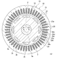
- FIG. 2 is a cross-sectional view of a rotor and a stator according to an embodiment.
- FIG. 3 is a partial cross-sectional view of the stator of one embodiment.
- FIG. 4 is a perspective view of the stator of one embodiment.
- FIG. 5 is a plan view of the stator of one embodiment.
- FIG. 6 is a perspective view of the phase coil portion of one embodiment.
- FIG. 7 is a front view of the terminal conductor of one embodiment.
- FIG. 8 is a front view of the hairpin conductor of one embodiment.
- FIG. 9 is a front view of the interlayer hairpin conductor of one embodiment.
- FIG. 10 is a front view of the first folding conductor of one embodiment.
- the Z-axis direction appropriately shown in each figure is a vertical direction in which the positive side is the "upper side” and the negative side is the “lower side”.
- the central axis J appropriately shown in each figure is a virtual line that is parallel to the Z-axis direction and extends in the vertical direction.
- the axial direction of the central axis J that is, the direction parallel to the vertical direction is simply referred to as "axial direction”
- the upper side is referred to as "axial direction one side”
- the lower side is referred to as "axial direction other side”.
- the radial direction centered on the central axis J may be simply referred to as "diametrical direction”.
- circumferential direction centered on the central axis J is simply called “circumferential direction”
- the clockwise direction when viewed from above is called “one side in the circumferential direction”
- the counterclockwise direction when viewed from above is called “circumferential direction”.
- the other side of the direction is sometimes referred to as "the other side of the direction”.
- FIG. 1 is a schematic cross-sectional view of the motor 1 of the present embodiment.
- the motor 1 of the present embodiment is an inner rotor type motor.
- the center of the motor 1 is the central axis J.
- the rotor 3 can rotate around the central axis J.
- the rotor 3 is arranged radially inside the annular stator 10. That is, the rotor 3 faces the stator 10 in the radial direction.
- the rotor 3 has a shaft 3a, a rotor magnet 3b, and a rotor core 3c.
- the shaft 3a extends in the axial direction along the central axis J.
- the shaft 3a is, for example, a columnar shape extending in the axial direction about the central axis J.
- the shaft 3a is rotatably supported around the central axis J by bearings 5a and 5b.
- the rotor core 3c is configured by laminating electromagnetic steel sheets.
- the rotor core 3c has a tubular shape extending in the axial direction.
- the inner peripheral surface of the rotor core 3c is fixed to the outer peripheral surface of the shaft 3a.
- the rotor core 3c is located between the pair of bearings 5a and 5b in the axial direction.
- the rotor core 3c is provided with a holding hole 3h into which the rotor magnet 3b is inserted and fixed.
- the stator core 20 is an annular shape centered on the central axis J.
- the stator core 20 is made of a plurality of electrical steel sheets laminated along the axial direction.
- the stator core 20 has a cylindrical core back portion 21 centered on the central axis J, and a plurality of teeth portions 22 extending radially inward from the core back portion 21.
- the plurality of teeth portions 22 are arranged at equal intervals in the circumferential direction.
- An umbrella portion 22a is provided at the tip portion on the inner side in the radial direction of the tooth portion 22.
- the umbrella portion 22a projects on both sides in the circumferential direction with respect to the teeth portion 22. That is, the circumferential dimension of the umbrella portion 22a is larger than the circumferential dimension of the teeth portion 22.
- the surface of the umbrella portion 22a facing inward in the radial direction faces the outer peripheral surface of the rotor 3 in the radial direction via a gap.
- the stator coil 30 is mounted on the teeth portion 22.
- a slot 29 is provided between the tooth portions 22 adjacent to each other in the circumferential direction. That is, the stator core 20 is provided with a plurality of slots 29 arranged in the circumferential direction.
- One slot 29 is provided with layers 29a, 29b, 29c, and 29d having four or more even layers (four layers in this embodiment) arranged in the radial direction.
- the four layers are referred to as a first layer 29a, a second layer 29b, a third layer 29c, and a fourth layer 29d, respectively, from the outside to the inside in the radial direction.
- the first layer 29a is the first layer
- the second layer 29b is the second layer
- the third layer 29c is the third layer
- the fourth layer 29d Is the fourth layer.
- the width dimension along the circumferential direction of the slot 29 of the present embodiment is slightly larger than the dimension along the circumferential direction of the conductor 50.
- one conductor 50 is arranged in each of the layers 29a, 29b, 29c, and 29d.
- four conductors 50 are arranged in a row along the radial direction.
- a U-phase bus bar (phase bus bar) 9U is connected to the U-phase coil portion 30U. An alternating current is passed through the U-phase coil portion 30U via the U-phase bus bar 9U.
- a V-phase bus bar (phase bus bar) 9V is connected to the V-phase coil portion 30V. An alternating current is passed through the V-phase coil portion 30V via the V-phase bus bar 9V.
- a W-phase bus bar (phase bus bar) 9W is connected to the W-phase coil portion 30W. An alternating current is passed through the W-phase coil portion 30W via the W-phase bus bar 9W.
- the phases of the alternating currents flowing through the U-phase coil section 30U, the V-phase coil section 30V, and the W-phase coil section 30W are each shifted by 120 °.
- the neutral point bus bar 8 is connected to the U-phase coil portion 30U, the V-phase coil portion 30V, and the W-phase coil portion 30W.
- Neutral point The bus bar 8 constitutes the neutral point of the three-phase circuit.
- FIG. 6 is a perspective view of one phase coil portion 30A of the three-phase phase coil portions 30A.
- the phase coil unit 30A described below may be any of the U-phase coil unit 30U, the V-phase coil unit 30V, and the W-phase coil unit 30W.
- phase coil portion 30A has at least two or more conductor connectors 60.
- the phase coil portion 30A includes two conductor connecting bodies 60.
- the conductor connecting body 60 is configured by connecting a plurality of conductors 50 in series.
- first conductor connecting body 60A when the two conductor connecting bodies 60 are distinguished from each other, one is referred to as a first conductor connecting body 60A and the other is referred to as a second conductor connecting body 60B.
- the conductor 50 is configured by winding a flat wire. Therefore, the space factor of the conductor 50 in the slot 29 can be improved as compared with the case of using the round wire.
- the "flat wire” is a wire rod having a quadrangular cross-sectional shape or a substantially quadrangular cross-sectional shape. As used herein, the term “substantially square” includes a square with rounded corners.
- the conductor 50 in this embodiment has an enamel coating on its surface.
- the stator 10 of the present embodiment can be assembled by inserting a plurality of conductors 50 into the slots 29 of the stator core 20 from the upper side and welding them from the lower side. Therefore, the assembly process can be simplified without requiring a complicated assembly process.
- the terminal conductor 51 has one terminal portion 50c, one linear portion 50a, and one connecting portion 50b.
- the end portion 50c is located at the upper end portion of the end conductor 51.
- the end portion 50c is bent in the circumferential direction with respect to the straight portion 50a.
- the end portion 50c and the connecting portion 50b are bent in opposite directions in the circumferential direction.
- the terminal portion 50c extends from the upper end of the straight line portion 50a to the other side ⁇ 2 in the circumferential direction
- the connecting portion 50b extends from the lower end of the straight line portion 50a to the one side ⁇ 1 in the circumferential direction.
- the hairpin conductor 52 has two straight portions 50a, two connecting portions 50b, and one bent portion 50d.
- the bent portion 50d is arranged at the upper end portion of the hairpin conductor 52.
- the bent portion 50d passes the two straight portions 50a to each other. That is, in the hairpin conductor 52, the two straight portions 50a are connected to each other via the bent portion 50d.
- the two connecting portions 50b are connected to the lower ends of different linear portions 50a.
- the two connecting portions 50b are lined up in the number of slots per pole.
- the number of slots per pole means the number of slots 29 of the stator 10 arranged between one magnetic pole of the rotor 3 in the combination of the rotor 3 and the stator 10.
- the number of slots per pole is calculated by (the total number of slots of the stator 10) / (the number of magnetic poles of the rotor 3).
- the number of magnetic poles of the rotor 3 is 8
- the number of slots of the stator 10 is 48, so that the number of slots per pole is 6.
- the two connecting portions 50b are separated from each other by 6 slots in the circumferential direction.
- the two connecting portions 50b are arranged in the number of slots per pole (6 slots in this embodiment).
- the two connecting portions 50b are bent in opposite directions in the circumferential direction.
- one located on one side ⁇ 1 in the circumferential direction extends from the lower end of the straight portion 50a to ⁇ 1 on one side in the circumferential direction, and the other located on the other side ⁇ 2 in the circumferential direction is circumferentially oriented from the lower end of the straight portion 50a. It extends to the other side ⁇ 2.
- the structure of the interlayer bent portion 50e of the interlayer hairpin conductor 53 is mainly different from that of the hairpin conductor 52.
- the shape of the interlayer bent portion 50e is slightly different from that of the bent portion 50d of the hairpin conductor 52. As shown in FIG. 12, the first conductor connecting body 60A and the second conductor connecting body 60B are each provided with two interlayer hairpin conductors 53.
- the first folded conductor 54 has two straight portions 50a, two connecting portions 50b, and one first folded portion (folded portion) 50f.
- the second folded conductor 55 has two straight portions 50a, two connecting portions 50b, and one second folded portion (folded portion) 50 g.
- the first folded-back portion 50f and the second folded-back portion 50 g are arranged at the upper ends of the first folded-back conductor 54 or the second folded-back conductor 55, respectively.
- the first folded portion 50f and the second folded portion 50g pass the two straight portions 50a to each other. That is, in the first folding conductor 54 and the second folding conductor 55, the two straight portions 50a are connected to each other via the first folding portion 50f or the second folding portion 50g, respectively.
- the two connecting portions 50b are bent to the other side ⁇ 2 in the circumferential direction. That is, in the first folding conductor 54 and the second folding conductor 55, the two connecting portions 50b each extend from the lower end of the straight line portion 50a to the other side ⁇ 2 in the circumferential direction.
- the distances between the two connecting portions 50b are different from each other.
- the two connecting portions 50b are arranged in the number of slots per pole + 1 (7 slots in the present embodiment).
- the two connecting portions 50b are lined up with the number of slots per pole-1 (5 slots in this embodiment). Therefore, the first folded-back portion 50f has a larger crossover amount in the circumferential direction by two slots than the second folded-back portion 50g.
- the first folded portion 50f has a bent portion 50fa that bends from one side ⁇ 1 in the circumferential direction to ⁇ 2 on the other side in the circumferential direction, and two extending portions 50fb and 50fc connected to both ends of the bent portion 50fa.
- the first folded-back portion 50f extends from the slot 29 to one side ⁇ 1 in the circumferential direction at the two extending portions 50fb and 50fc.
- the two extending portions 50fb and 50fc extend in parallel with each other before and after the bent portion 50fa.
- the second folded portion 50 g has a bent portion 50 ga that bends from one side ⁇ 1 in the circumferential direction to ⁇ 2 on the other side in the circumferential direction, and two extending portions 50 gb and 50 gc connected to both ends of the bent portion 50 ga.
- the second folded-back portion 50 g extends from the slot 29 to one side ⁇ 1 in the circumferential direction at the two extended portions 50 gb and 50 gc.
- the two extending portions 50gb and 50gc extend in parallel with each other before and after the bent portion 50ga.
- the first conductor connecting body 60A is provided with one first folding conductor 54.
- the second conductor connecting body 60B is provided with one second folding conductor 55.
- the two terminal conductors 51 are arranged at the ends of both ends of the first conductor connecting body 60A, respectively, and the first folding conductor 54 is substantially in the middle. Is placed.
- the first conductor connecting body 60A has two terminal conductors 51, twelve hairpin conductors 52, two interlayer hairpin conductors 53, and a first folding conductor 54.
- first conductor connecting body 60A one end conductor 51, three hairpin conductors 52, one interlayer hairpin conductor 53, three hairpin conductors 52, a first folding conductor 54, and three hairpins.
- the conductor 52, one interlayer hairpin conductor 53, three hairpin conductors 52, and the other end conductor 51 are connected in this order.
- the first conductor connecting body 60A includes a plurality of (32 pieces) straight portions 50a, and a plurality of (14 pieces) bent portions 50d and 50e passing the straight portions 50a on the upper side (one side in the axial direction) of the stator core 20. It has a plurality of (16) connecting portions 50b for connecting the conductors 50 to each other on the lower side (the other side in the axial direction) of the stator core 20.
- the first conductor connecting body 60A is wave-wound every 6 slots toward ⁇ 1 on one side in the circumferential direction from one end portion 50c to the first folded portion 50f. Further, the first conductor connecting body 60A is wave-wound every 6 slots toward the other side ⁇ 2 in the circumferential direction from the first folded-back portion 50f to the other end portion 50c.
- one end portion 50c connected to any of the compatible bus bars 9U, 9V, and 9W is referred to as an input side end portion (first end portion) 63 and is neutral.
- the other end portion 50c connected to the point bus bar 8 is referred to as a neutral point side end portion (second end portion) 64.
- the region that is wave-wound in the circumferential direction one side ⁇ 1 between the input side end portion 63 and the first folded portion 50f is referred to as a first portion 61.
- the region that is wave-wound on the other side ⁇ 2 in the circumferential direction between the first folded-back portion 50f and the neutral point side end portion 64 is referred to as a second portion 62.
- the circumferential direction one side ⁇ 1 is defined as the forward direction
- the circumferential direction other side ⁇ 2 is defined as the reverse direction
- the first portion 61 can be referred to as a forward direction portion
- the second portion 62 can be referred to as a reverse direction portion.
- the first conductor connecting body 60A has an input side end portion 63, a first portion 61 wave-wound from the input side end portion 63 to one side ⁇ 1 in the circumferential direction, and an end of ⁇ 1 on one side in the circumferential direction of the first part 61.
- the second portion 62 wave-wound from the first folded-back portion 50f to the other side ⁇ 2 in the circumferential direction, and the other side ⁇ 2 in the circumferential direction of the second portion 62. It has a neutral point side end portion 64 to be connected.
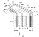
- FIG. 13 is a schematic view showing an arrangement in the slot 29 through which the straight line portion 50a of the first portion 61 of the first conductor connecting body 60A passes.
- FIG. 14 is a schematic view showing an arrangement in the slot 29 through which the straight portion 50a of the second portion 62 of the first conductor connecting body 60A passes.
- the first conductor connecting body 60A orbits in the first portion 61 on one side ⁇ 1 in the circumferential direction by two turns.
- the first portion 61 may make two or more laps.
- the first conductor connecting body 60A orbits in the second portion 62 on the other side ⁇ 2 in the circumferential direction by two turns.
- the second portion 62 may orbit the other side ⁇ 2 in the circumferential direction by the same number as the first portion 61.
- the first portion 61 and the second portion 62 of the first conductor connecting body 60A each have an interlayer bending portion 50e at a boundary where the circumference changes.
- the "boundary in which the lap changes” is the boundary between the first lap and the second lap around the central axis J, and the boundary between the Nth lap and the N + 1 lap in the arrangement of the first part 61 and the second part 62.
- Etc. which means a region where the number of laps changes.
- the linear portions 50a arranged in the circumferential direction are alternately arranged in the first layer 29a and the second layer 29b between the input side end portion 63 and the interlayer bending portion 50e. Pass through and go around.
- the first conductor connecting body 60A extends from the second layer 29b to the third layer 29c at the interlayer bending portion 50e of the first portion 61.
- the first conductor connecting body 60A orbits between the interlayer bending portion 50e and the first folded portion 50f by alternately passing straight portions 50a arranged in the circumferential direction through the third layer 29c and the fourth layer 29d. ..
- the straight line portion 50a passes through the same slot 29 on the first and second laps.
- the linear portions 50a arranged in the circumferential direction between the first folded portion 50f and the interlayer bending portion 50e are formed on the third layer 29c and the fourth layer 29d. Pass alternately and go around.
- the first conductor connecting body 60A extends from the third layer 29c to the second layer 29b at the interlayer bending portion 50e of the second portion 62.
- the first conductor connecting body 60A orbits between the interlayer bending portion 50e and the neutral point side end portion 64 by alternately passing straight portions 50a arranged in the circumferential direction through the first layer 29a and the second layer 29b. do.
- the straight line portion 50a passes through the same slot 29 on the first and second laps.
- the second conductor connecting body 60B has substantially the same structure as the first conductor connecting body 60A, but mainly differs in the structure of the folded portion and the position of the slot 29 through which it passes.
- the two end conductors 51 are arranged at the ends of both ends of the second conductor connecting body 60B, respectively, and the second folding conductor 55 is substantially in the middle. Is placed.
- the second conductor connecting body 60B has two terminal conductors 51, twelve hairpin conductors 52, two interlayer hairpin conductors 53, and a second folding conductor 55.
- the conductor 52, one interlayer hairpin conductor 53, three hairpin conductors 52, and the other end conductor 51 are connected in this order.
- the second conductor connecting body 60B includes a plurality of (32 pieces) straight portions 50a, and a plurality of (14 pieces) bent portions 50d and 50e passing the straight portions 50a on the upper side (one side in the axial direction) of the stator core 20. It has a plurality of (16) connecting portions 50b for connecting the conductors 50 to each other on the lower side (the other side in the axial direction) of the stator core 20.
- the second conductor connecting body 60B is 6 toward the circumferential direction ⁇ 1 during the period from the input side end portion 63, which is one end portion 50c, to the second folded portion 50 g (first portion 61). Waves are wound for each slot. Further, the second conductor connecting body 60B has a circumferential direction opposite side ⁇ 2 from the second folded-back portion 50g to the other end portion 50c, which is the neutral point side end portion 64 (second portion 62). It is waved every 6 slots toward.
- the second conductor connecting body 60B has an input side end portion 63, a first portion 61 wave-wound from the input side end portion 63 to one side ⁇ 1 in the circumferential direction, and ⁇ 1 on one side in the circumferential direction of the first part 61.
- It has a neutral point side end portion 64, which is connected to the portion.
- FIG. 15 is a schematic view showing an arrangement in the slot 29 through which the straight line portion 50a of the first portion of the second conductor connecting body 60B passes.
- FIG. 16 is a schematic view showing an arrangement in the slot 29 through which the straight line portion 50a of the second portion of the second conductor connecting body 60B passes.
- the second conductor connecting body 60B orbits in the first portion 61 on one side ⁇ 1 in the circumferential direction by two turns, and in the second portion 62, the same number as the first portion 61 (that is, two turns) on the other side ⁇ 2 in the circumferential direction. Just go around.
- the first portion 61 and the second portion 62 of the second conductor connecting body 60B each have an interlayer bending portion 50e at a boundary where the circumference changes.
- the second conductor connecting body 60B orbits between the input side end portion 63 and the interlayer bending portion 50e by alternately passing the linear portions 50a arranged in the circumferential direction through the first layer 29a and the second layer 29b.
- the second conductor connecting body 60B extends from the second layer 29b to the third layer 29c at the interlayer bending portion 50e of the first portion 61.
- the second conductor connecting body 60B orbits between the interlayer bending portion 50e and the second folded portion 50g by alternately passing straight portions 50a arranged in the circumferential direction through the third layer 29c and the fourth layer 29d. ..
- the straight line portion 50a passes through the same slot 29 on the first and second laps.
- a linear portion 50a arranged in the circumferential direction between the second folded portion 50g and the interlayer bending portion 50e is formed on the third layer 29c and the fourth layer 29d. Pass alternately and go around.
- the second conductor connecting body 60B extends from the third layer 29c to the second layer 29b at the interlayer bending portion 50e of the second portion 62.
- the second conductor connecting body 60B orbits between the interlayer bending portion 50e and the neutral point side end portion 64 by alternately passing straight portions 50a arranged in the circumferential direction through the first layer 29a and the second layer 29b. do.
- the straight line portion 50a passes through the same slot 29 on the first and second laps.
- the conductor connecting body 60 makes two rounds in the first portion 61 and the second portion 62. Therefore, the density of the magnetic flux generated in the stator 10 can be increased as compared with the case where the conductor connecting body 60 makes only one round, and the output of the motor 1 can be increased.
- the conductor connecting body 60 may make two or more turns in the first portion 61 and the second portion 62.
- N is a natural number
- M be an odd natural number (1, 3, 5, ).
- the straight line portions 50a arranged in the circumferential direction are combined with the M layer (for example, the first layer) layer and the M + 1st layer (for example, the second layer). Pass alternately between them and make one lap.
- the conductor connecting body 60 changes from the M + 1 layer (for example, the second layer) to the M + second layer (for example, the third layer) at the boundary between the Nth lap (for example, the first lap) and the N + 1th lap (for example, the second lap). It has an interlayer bent portion 50e extending across the layer. According to this embodiment, the phase coil portion 30A can be simply configured even when the conductor connecting body 60 is used for 2 weeks or more.
- the plurality of linear portions 50a have the number of slots per pole (6 slots in the present embodiment). Line up in the circumferential direction. That is, the first conductor connecting body 60A is wound around the stator core 20 by so-called all-node winding. In the all-node winding, the conductor 50 having the same phase is arranged in one slot 29, it is easy to secure the insulation between the U phase, the V phase, and the W phase, and the performance of the motor 1 can be stabilized.
- the conductor connecting body 60 has a configuration in which the conductors 50 are laminated in the radial direction in the first portion 61 and the second portion 62. As a result, the density of the magnetic flux generated by the current flowing through each conductor 50 can be increased according to the number of laps of the conductor connector 60.
- the first portion 61 of the first conductor connecting body 60A and the first part 61 of the second conductor connecting body 60B pass through different slots 29 from each other.
- the second portion 62 of the first conductor coupling 60A and the second portion 62 of the second conductor coupling 60B pass through different slots 29 from each other.
- the slot 29 through which the straight line portion 50a passes is displaced by one slot from the first portion 61 of the first conductor connecting body 60A to ⁇ 1 on one side in the circumferential direction. ..
- the slot 29 through which the straight line portion 50a passes is only one slot on the other side ⁇ 2 in the circumferential direction with respect to the second portion 62 of the first conductor connecting body 60A. It is out of alignment. That is, the first portion 61 of the plurality of conductor connectors 60 having the same phase is sequentially arranged in the slots 29 arranged one by one on one side ⁇ 1 in the circumferential direction. Further, the second portion 62 of the plurality of conductor connecting bodies 60 having the same phase is sequentially arranged in the slots 29 arranged one by one on the other side ⁇ 2 in the circumferential direction.
- the first portion 61 of the first conductor connecting body 60A and the second part 62 of the second conductor connecting body 60B are arranged in the same slot. Only the conductor connecting body 60 having the same phase passes through one slot 29, and the insulation between the plurality of phase coil portions 30A can be easily ensured.
- the two end portions 50c extend from slots 29 separated by the number of slots per pole + 1 (7 slots) in the circumferential direction. Get out.
- the neutral point side end portion 64 located on one side ⁇ 1 in the circumferential direction is compared with the input side end portion 63 located on the other side ⁇ 2 in the circumferential direction. , Extends one slot longer on one side ⁇ 1 in the circumferential direction. Therefore, the two end portions 50c of the first conductor connecting body 60A are arranged apart by the number of slots per pole (6 slots) in the circumferential direction.
- the two end portions 50c (input side end portion 63 and neutral point side end portion 64) are separated from the slot 29 by the number of slots per pole-1 (5 slots) in the circumferential direction. Extend out.
- the input side end portion 63 located on the other side ⁇ 2 in the circumferential direction is compared with the neutral point side end portion 64 located on the one side ⁇ 1 in the circumferential direction. , Extends one slot longer on one side ⁇ 1 in the circumferential direction. Therefore, the two end portions 50c of the second conductor connecting body 60B are arranged apart by the number of slots per pole (6 slots) in the circumferential direction.
- the input side end portion 63 of the in-phase conductor coupling 60 and the neutral point-side end portion 64 of the in-phase conductor coupling 60 are arranged apart by the number of slots for each pole in the circumferential direction. Therefore, the input side end portions 63 and the neutral point side end portions 64 of the plurality of conductor connecting bodies 60 (first conductor connecting body 60A and second conductor connecting body 60B) can be arranged so as to be overlapped with each other.
- the input-side end portions 63 of the in-phase conductor connecting bodies 60 are arranged side by side in the radial direction and are connected to each other.
- the input-side end 63 of the in-phase conductor connector 60 is both connected to a compatible bus bar (U-phase bus bar 9U, V-phase bus bar 9V, or W-phase bus bar 9W).
- the neutral point side end portions 64 of the in-phase conductor connecting bodies 60 are arranged side by side in the radial direction and are connected to each other. Further, the neutral point side end portion 64 of the in-phase conductor connecting body 60 is both connected to the neutral point bus bar 8.
- the input side end portions 63 of the two or more conductor connecting bodies 60 of one phase coil portion 30A are electrically connected to each other.
- the neutral point side end portions 64 of the two or more conductor connecting bodies 60 of one phase coil portion 30A are electrically connected to each other.
- the plurality of conductor connectors 60 of one phase coil portion 30A are connected in parallel to each other.
- At least one of the neutral point bus bar 8 and the compatible bus bars 9U, 9V, and 9W is located at the radial position of the folded portion 50f, 50 g, the radial position of the folded portion 50f, 50 g, the input side end portion 63, and the neutral point. It is located between the radial position of the side end portion 64. That is, when viewed from the axial direction, at least one of the neutral point bus bar 8 and the compatible bus bars 9U, 9V, 9W is arranged between the inner edge and the outer edge of the coil end of the stator coil 30. Therefore, it is possible to prevent at least one of the neutral point bus bar 8 and the compatible bus bars 9U, 9V, and 9W from projecting to both sides in the radial direction with respect to the stator coil 30.
- FIG. 17 is a schematic view showing a first folded-back portion 50f and a second folded-back portion 50 g.
- the first conductor connecting body 60A folds the wave winding direction from the circumferential direction ⁇ 1 to the circumferential direction other side ⁇ 2 at the first folded portion 50f.
- the second conductor connecting body 60B folds the wave winding direction from one side ⁇ 1 in the circumferential direction to ⁇ 2 on the other side in the circumferential direction at the second folded portion 50g.
- the two slots 29 extending from the first folded portion 50f are separated by 7 slots (that is, the number of slots per pole + 1).
- the two slots 29 extending from the second folded portion 50 g are separated by 5 slots (that is, the number of slots per pole-1).
- the two slots 29 from which the first folded portion 50f extends are arranged outside in the circumferential direction with respect to the two slots 29 from which the second folded portion 50g extends. Further, the first folded-back portion 50f passes above the second folded-back portion 50g. The first folded-back portion 50f is arranged so as to straddle the second folded-back portion 50g from both the upper side and the circumferential direction. Further, four slots 29 are arranged between the two extending slots 29 of the second folded portion 50 g. Bending portions 50d of other phases extend from these four slots 29.
- the bent portion 50fa of the first folded portion 50f and the bent portion 50ga of the second folded portion 50g are arranged so as to overlap each other in the circumferential direction.
- One extending portion 50fb of the first folded portion 50f and one extending portion 50gb of the second folded portion 50g extend in parallel with each other.
- the other extending portion 50fc of the first folded portion 50f and the other extending portion 50gc of the second folded portion 50g extend in parallel with each other. That is, the folded portions (first folded portion 50f and second folded portion 50 g) of the conductor connecting body 60 having the same phase extend in parallel with each other before and after the bent portions 50fa and 50ga. Therefore, the folded portions (first folded portion 50f and second folded portion 50 g) of the conductor connecting body 60 having the same phase can be compactly laminated, and the stator coil 30 can be miniaturized.
- the extending portions 50fb, 50fc, 50gb, and 50gc of the first folded portion 50f and the second folded portion 50 g extend in parallel with the bent portions 50d of the other phases. Therefore, the first folded-back portion 50f and the second folded-back portion 50g can be compactly laminated together with the bent portion 50d of the other phase, and the stator coil 30 can be downsized.
- first folded-back portion 50f and the second folded-back portion 50g are arranged so as to overlap each other in the axial direction.
- the first folded-back portion 50f and the second folded-back portion 50g project upward (one side in the axial direction) from the bent portion 50d of the other phase.
- the first folded portion 50f and the second folded portion 50g overlap each other on the upper side (one side in the axial direction) of the bent portion 50d of the other phase at the bent portions 50fa and 50ga, respectively.
- the folded portions (first folded portion 50f and second folded portion 50 g) of the conductor connecting body 60 having the same phase are arranged so as to overlap each other in the axial direction, and are arranged on one side in the axial direction from the bent portions 50d of the other phases. It protrudes and overlaps one side of the bent portion 50d of the other phase in the axial direction. Therefore, it is possible to prevent the folded-back portion (first folded-back portion 50f and second folded-back portion 50g) from projecting radially inward or radially outward with respect to the bent portion 50d of the other phase. According to this embodiment, the radial dimension of the stator coil 30 can be reduced in size.
- FIG. 18 is a schematic view showing a layer in the slot 29 through which the conductor connecting body 60 (the first conductor connecting body 60A and the second conductor connecting body 60B) of one phase coil portion 30A passes.
- the slot 29 from which the input side end portion 63 of the second conductor connecting body 60B extends is set as the first slot, and is numbered up to the 48th slot toward the other side ⁇ 2 in the circumferential direction.
- the neutral point side end portion 64 of the second conductor connecting body 60B extends from the 44th slot.
- the input side end portion 63 extends from the second slot, and the neutral point side end portion 64 extends from the 43rd slot.
- the conductor connecting body 60 since the plurality of conductor connecting bodies 60 having the same phase are arranged in the same slot 29, it is easy to secure insulation. Further, according to the present embodiment, since the conductor connecting body 60 has the folded-back portions 50f and 50g, the two end portions 50c can be arranged so as to be close to one side in the radial direction. That is, according to the present embodiment, in all the phase coil portions 30A, the input side end portion 63 and the neutral point side end portion 64 extend from the outermost layer (first layer 29a). Therefore, the connection steps between the bus bars 9U, 9V, 9W, 8 and the input side end portion 63 and the neutral point side end portion 64 can all be performed from the outside in the radial direction. As a result, the manufacturing process of the stator 10 and the motor 1 can be simplified.
- the phase coil portion 30A of the other phase is arranged so as to be staggered by 4 slots in order with respect to the phase coil portion 30A shown in FIG.
- the phase coil portion 30A shown in FIG. 18 is a U-phase coil portion 30U.
- the two input side end portions 63 extend from the fifth and sixth slots 29, and the two neutral end side ends 64 extend from the 47th and 48th slots.
- the two input-side end portions 63 extend from the ninth and tenth slots 29, and the two neutral-side end portions 64 extend from the third and fourth slots. Get out.
- Bent part, 60 ... Conductor connection Body, 61 ... 1st part, 62 ... 2nd part, 63 ... Input side end part (1st end part), 64 ... Neutral point side end part (2nd end part), J ... Central axis, ⁇ 1 ... Circumference One side in the direction, ⁇ 2 ... The other side in the circumferential direction
Abstract
One aspect of a stator of the present invention comprises phase coil parts of a plurality of phases star-connected to each other. The phase coil parts have a plurality of conductor connectors formed by connecting a plurality of conductors in series. The conductor connectors are arranged in a circle by being alternately passed through an Mth layer and an M+1th layer of slots. The conductor connectors have a first terminal part, a first section wave-wound from the first terminal part to one side in the circumferential direction, a folded-back part that connects to an end of the first section on one side in the circumferential direction, a second section which is wave-wound from the folded-back part to the other side in the circumferential direction, and a second terminal part that connects to an end of the second section on the other side in the circumferential direction. The first sections of the plurality of conductor connectors of the same phase are disposed in order in slots that are arranged next to each other one-by-one to one side in the circumferential direction. The second sections of the plurality of conductor connectors of the same phase are disposed in order in slots that are arranged next to each other one-by-one to the other side in the circumferential direction. The first terminal part and the second terminal part extend out from the outermost layer.
Description
本発明は、ステータおよびモータに関する。
本願は、2020年9月30日に日本に出願された特願2020-165709に基づき優先権を主張し、その内容をここに援用する。 The present invention relates to a stator and a motor.
This application claims priority based on Japanese Patent Application No. 2020-165709 filed in Japan on September 30, 2020, the contents of which are incorporated herein by reference.
近年、矩形状の導線をスロット内に配置することで、スロット内における導線の占積率の向上させたステータが知られている(特許文献1)。
In recent years, a stator has been known in which the space factor of the conducting wire in the slot is improved by arranging the rectangular conducting wire in the slot (Patent Document 1).
特許文献1に開示されているモータは、導線の端部がステータの径方向内縁および径方向外縁にそれぞれ配置される。導線の端部には、中性点を構成する中性点バスバーや、導線の電流を流すための相用バスバーが接続される。このように、従来技術のステータでは、バスバーとの接続工程の作業性が悪いという問題があった。
In the motor disclosed in Patent Document 1, the end portions of the conducting wires are arranged at the radial inner edge and the radial outer edge of the stator, respectively. At the end of the conductor, a neutral point bus bar constituting the neutral point and a phase bus bar for passing the current of the conductor are connected. As described above, the stator of the prior art has a problem that the workability of the connection process with the bus bar is poor.
本発明は、上記事情に鑑みて、バスバーとの接続を容易に行うことができるステータおよびモータを提供することを目的の一つとする。
In view of the above circumstances, one of the objects of the present invention is to provide a stator and a motor that can be easily connected to a bus bar.
本発明のステータの一つの態様は、中心軸線を中心とする環状であり周方向に並ぶ複数のスロットが設けられるステータコアと、前記ステータコアに装着される複数相の相コイル部と、を備える。前記相コイル部は、複数の導体が直列に連結されて構成される導体連結体を有する。前記導体連結体は、前記スロットを通過する複数の直線部と、前記ステータコアの軸方向一方側で前記直線部同士を渡す複数の曲げ部と、前記ステータコアの軸方向他方側で前記導体同士を連結する複数の連結部と、を有する。1つの前記スロットには、径方向に並ぶ偶数層のレイヤが設けられる。前記導体連結体は、Mを奇数の自然数として、周方向に並ぶ前記直線部をM層目の前記レイヤとM+1層目の前記レイヤに交互に通過させて周回する。前記導体連結体は、第1末端部と、前記第1末端部から周方向一方側に波巻きされる第1部分、前記第1部分の周方向一方側の端部に接続される折り返し部と、前記折り返し部から周方向他方側に波巻きされる第2部分と、前記第2部分の周方向他方側の端部に接続される第2末端部と、を有する。同相の複数の前記導体連結体の前記第1部分は、周方向一方側に1つずつ並ぶ前記スロットに順に配置される。同相の複数の前記導体連結体の前記第2部分は、周方向他方側に1つずつ並ぶ前記スロットに順に配置される。前記第1末端部および前記第2末端部は、最外層の前記レイヤから延び出ている。1つの前記相コイル部は少なくとも2個以上の前記導体連結体を有する。1つの前記相コイル部の2個以上の前記導体連結体の前記第1末端部同士は電気的に接続される。1つの前記相コイル部の2個以上の前記導体連結体の前記第2末端部同士は電気的に接続される。
One aspect of the stator of the present invention includes a stator core which is annular around the central axis and is provided with a plurality of slots arranged in the circumferential direction, and a plurality of phase phase coil portions mounted on the stator core. The phase coil portion has a conductor connecting body in which a plurality of conductors are connected in series. The conductor connecting body connects a plurality of straight portions passing through the slot, a plurality of bending portions passing the straight portions on one side in the axial direction of the stator core, and the conductors on the other side in the axial direction of the stator core. It has a plurality of connecting portions and a plurality of connecting portions. One of the slots is provided with even layers arranged in the radial direction. The conductor connecting body orbits the conductor connecting body by alternately passing the straight line portions arranged in the circumferential direction through the layer of the M layer and the layer of the M + 1 layer, where M is an odd natural number. The conductor connecting body includes a first terminal portion, a first portion that is wave-wound from the first terminal portion to one side in the circumferential direction, and a folded portion connected to one end portion in the circumferential direction of the first portion. It has a second portion that is wave-wound from the folded portion to the other side in the circumferential direction, and a second end portion that is connected to the end portion of the second portion on the other side in the circumferential direction. The first portion of the plurality of in-phase conductor connectors is sequentially arranged in the slots arranged one by one on one side in the circumferential direction. The second portion of the plurality of in-phase conductor connectors is sequentially arranged in the slots arranged one by one on the other side in the circumferential direction. The first terminal portion and the second terminal portion extend from the outermost layer. One said phase coil portion has at least two or more said conductor connectors. The first end portions of the two or more conductor connectors of one phase coil portion are electrically connected to each other. The second end portions of the two or more conductor connectors of one phase coil portion are electrically connected to each other.
本発明のモータの一つの態様は、上述のステータと、径方向においてステータに対向するロータと、を備える。
One aspect of the motor of the present invention includes the above-mentioned stator and a rotor facing the stator in the radial direction.
本発明の一つの態様によれば、バスバーとの接続を容易に行うことができるステータおよびモータを提供できる。
According to one aspect of the present invention, it is possible to provide a stator and a motor that can be easily connected to a bus bar.
各図に適宜示すZ軸方向は、正の側を「上側」とし、負の側を「下側」とする上下方向である。各図に適宜示す中心軸線Jは、Z軸方向と平行であり、上下方向に延びる仮想線である。以下の説明においては、中心軸線Jの軸方向、すなわち上下方向と平行な方向を単に「軸方向」と呼び、上側を「軸方向一方側」と呼び、下側を「軸方向他方側」と呼ぶ場合がある。また、中心軸線Jを中心とする径方向を単に「径方向」と呼ぶ場合がある。さらに、中心軸線Jを中心とする周方向を単に「周方向」と呼び、上側から見て時計回りの方向を「周方向一方側」と呼び、上側から見て反時計回りの方向を「周方向他方側」と呼ぶ場合がある。
The Z-axis direction appropriately shown in each figure is a vertical direction in which the positive side is the "upper side" and the negative side is the "lower side". The central axis J appropriately shown in each figure is a virtual line that is parallel to the Z-axis direction and extends in the vertical direction. In the following description, the axial direction of the central axis J, that is, the direction parallel to the vertical direction is simply referred to as "axial direction", the upper side is referred to as "axial direction one side", and the lower side is referred to as "axial direction other side". May be called. Further, the radial direction centered on the central axis J may be simply referred to as "diametrical direction". Further, the circumferential direction centered on the central axis J is simply called "circumferential direction", the clockwise direction when viewed from above is called "one side in the circumferential direction", and the counterclockwise direction when viewed from above is called "circumferential direction". Sometimes referred to as "the other side of the direction".
なお、上下方向、上側、および下側とは、単に各部の配置関係等を説明するための名称であり、実際の配置関係等は、これらの名称で示される配置関係等以外の配置関係等であってもよい。さらに、軸方向一方側、および軸方向他方側として説明する方向は、互いに入れ替えた場合であっても、実施形態の効果を再現可能である。同様に、周方向一方側θ1、および周方向他方側θ2として説明する方向は、互いに入れ替えた場合であっても、実施形態の効果を再現可能である。
In addition, the vertical direction, the upper side, and the lower side are simply names for explaining the arrangement relations of each part, and the actual arrangement relations, etc. are the arrangement relations, etc. other than the arrangement relations, etc. indicated by these names. There may be. Further, the directions described as one side in the axial direction and the other side in the axial direction can reproduce the effect of the embodiment even when they are interchanged with each other. Similarly, the directions described as one side θ1 in the circumferential direction and θ2 on the other side in the circumferential direction can reproduce the effect of the embodiment even when they are interchanged with each other.
<第1実施形態>
図1は、本実施形態のモータ1の断面模式図である。
本実施形態のモータ1は、インナーロータ型のモータである。モータ1の中心は、中心軸線Jである。 <First Embodiment>
FIG. 1 is a schematic cross-sectional view of the motor 1 of the present embodiment.
The motor 1 of the present embodiment is an inner rotor type motor. The center of the motor 1 is the central axis J.
図1は、本実施形態のモータ1の断面模式図である。
本実施形態のモータ1は、インナーロータ型のモータである。モータ1の中心は、中心軸線Jである。 <First Embodiment>
FIG. 1 is a schematic cross-sectional view of the motor 1 of the present embodiment.
The motor 1 of the present embodiment is an inner rotor type motor. The center of the motor 1 is the central axis J.
モータ1は、ハウジング2と、ロータ3と、ステータ10と、ベアリングホルダ4と、ベアリング5a,5bと、を備える。ハウジング2は、ロータ3、ステータ10、ベアリングホルダ4、およびベアリング5a,5bを収容する。
The motor 1 includes a housing 2, a rotor 3, a stator 10, a bearing holder 4, and bearings 5a and 5b. The housing 2 houses the rotor 3, the stator 10, the bearing holder 4, and the bearings 5a and 5b.
ロータ3は、中心軸線Jを中心として回転可能である。ロータ3は、環状のステータ10の径方向内側に配置される。すなわち、ロータ3は、径方向においてステータ10に対向する。ロータ3は、シャフト3aと、ロータマグネット3bと、ロータコア3cと、を有する。
The rotor 3 can rotate around the central axis J. The rotor 3 is arranged radially inside the annular stator 10. That is, the rotor 3 faces the stator 10 in the radial direction. The rotor 3 has a shaft 3a, a rotor magnet 3b, and a rotor core 3c.
シャフト3aは、中心軸線Jに沿って軸方向に延びている。シャフト3aは、例えば、中心軸線Jを中心として軸方向に延びる円柱状である。シャフト3aは、ベアリング5a,5bによって中心軸線J回りに回転可能に支持されている。
The shaft 3a extends in the axial direction along the central axis J. The shaft 3a is, for example, a columnar shape extending in the axial direction about the central axis J. The shaft 3a is rotatably supported around the central axis J by bearings 5a and 5b.
図2は、図1のII-II線に沿うロータ3およびステータ10の断面図である。図3は、ステータ10の部分断面図であって、図2の一部を示す図である。
FIG. 2 is a cross-sectional view of the rotor 3 and the stator 10 along the line II-II of FIG. FIG. 3 is a partial cross-sectional view of the stator 10 and is a diagram showing a part of FIG. 2.
ロータコア3cは、電磁鋼板を積層して構成される。ロータコア3cは、軸方向に延びる筒状である。ロータコア3cの内周面は、シャフト3aの外周面に固定される。ロータコア3cは、軸方向において、一対のベアリング5a、5b間に位置する。ロータコア3cには、ロータマグネット3bが挿入され固定される保持孔3hが設けられる。
The rotor core 3c is configured by laminating electromagnetic steel sheets. The rotor core 3c has a tubular shape extending in the axial direction. The inner peripheral surface of the rotor core 3c is fixed to the outer peripheral surface of the shaft 3a. The rotor core 3c is located between the pair of bearings 5a and 5b in the axial direction. The rotor core 3c is provided with a holding hole 3h into which the rotor magnet 3b is inserted and fixed.
ロータマグネット3bは、径方向においてステータ10と対向する。ロータマグネット3bは、ロータコア3cに埋め込まれた状態で保持される。本実施形態のロータ3には、セグメントマグネットとしてのロータマグネット3bが、8個設けられる。すなわち、本実施形態のロータマグネット3bは、8極(8ポール)である。ロータ3のポール数は本実施形態に限定さない。また、ロータマグネット3bは、円環状のリングマグネットであってもよい。
The rotor magnet 3b faces the stator 10 in the radial direction. The rotor magnet 3b is held in a state of being embedded in the rotor core 3c. The rotor 3 of the present embodiment is provided with eight rotor magnets 3b as segment magnets. That is, the rotor magnet 3b of the present embodiment has 8 poles (8 poles). The number of poles of the rotor 3 is not limited to this embodiment. Further, the rotor magnet 3b may be an annular ring magnet.
ステータ10は、ロータ3と隙間を介して径方向に対向する。本実施形態においてステータ10は、ロータ3の径方向外側に位置する。ステータ10は、ステータコア20と、ステータコイル30と、複数の絶縁紙40と、を備える。
The stator 10 faces the rotor 3 in the radial direction via a gap. In this embodiment, the stator 10 is located radially outside the rotor 3. The stator 10 includes a stator core 20, a stator coil 30, and a plurality of insulating papers 40.
ステータコア20は、中心軸線Jを中心とする環状である。ステータコア20は、軸方向に沿って積層された複数の電磁鋼板からなる。ステータコア20は、中心軸線Jを中心とする円筒状のコアバック部21と、コアバック部21から径方向内側に向かって延びる複数のティース部22と、を有する。
The stator core 20 is an annular shape centered on the central axis J. The stator core 20 is made of a plurality of electrical steel sheets laminated along the axial direction. The stator core 20 has a cylindrical core back portion 21 centered on the central axis J, and a plurality of teeth portions 22 extending radially inward from the core back portion 21.
複数のティース部22は、周方向に等間隔に並ぶ。ティース部22の径方向内側の先端部には、アンブレラ部22aが設けられる。アンブレラ部22aは、ティース部22に対し周方向の両側に突出している。すなわち、アンブレラ部22aの周方向の寸法は、ティース部22の周方向の寸法よりも大きい。アンブレラ部22aの径方向内側を向く面は、ロータ3の外周面と径方向に隙間を介して対向する。
The plurality of teeth portions 22 are arranged at equal intervals in the circumferential direction. An umbrella portion 22a is provided at the tip portion on the inner side in the radial direction of the tooth portion 22. The umbrella portion 22a projects on both sides in the circumferential direction with respect to the teeth portion 22. That is, the circumferential dimension of the umbrella portion 22a is larger than the circumferential dimension of the teeth portion 22. The surface of the umbrella portion 22a facing inward in the radial direction faces the outer peripheral surface of the rotor 3 in the radial direction via a gap.
ティース部22には、ステータコイル30が装着される。周方向に隣り合うティース部22同士の間には、スロット29が設けられる。すなわち、ステータコア20には、周方向に並ぶ複数のスロット29が設けられる。
The stator coil 30 is mounted on the teeth portion 22. A slot 29 is provided between the tooth portions 22 adjacent to each other in the circumferential direction. That is, the stator core 20 is provided with a plurality of slots 29 arranged in the circumferential direction.
スロット29内には、ステータコイル30のコイルエンドを除く部分(後述する直線部50a)が収容される。また、スロット29内には、絶縁紙40が1つずつ配置される。絶縁紙40は、スロット29内において、ステータコイル30とステータコア20との絶縁を確保するために設けられる。
A portion of the stator coil 30 excluding the coil end (straight line portion 50a described later) is housed in the slot 29. Further, one insulating paper 40 is arranged in the slot 29. The insulating paper 40 is provided in the slot 29 in order to secure the insulation between the stator coil 30 and the stator core 20.
1つのスロット29には、径方向に並ぶ4層以上の偶数層(本実施形態では4層)のレイヤ29a、29b、29c、29dが設けられる。ここでは、4層のレイヤを径方向外側から内側に向かって、それぞれ第1レイヤ29a、第2レイヤ29b、第3レイヤ29c、第4レイヤ29dと呼ぶ。径方向外側から数えて、第1レイヤ29aは1層目のレイヤであり、第2レイヤ29bは2層目のレイヤであり、第3レイヤ29cは3層目のレイヤであり、第4レイヤ29dは4層目のレイヤである。
One slot 29 is provided with layers 29a, 29b, 29c, and 29d having four or more even layers (four layers in this embodiment) arranged in the radial direction. Here, the four layers are referred to as a first layer 29a, a second layer 29b, a third layer 29c, and a fourth layer 29d, respectively, from the outside to the inside in the radial direction. Counting from the outside in the radial direction, the first layer 29a is the first layer, the second layer 29b is the second layer, the third layer 29c is the third layer, and the fourth layer 29d. Is the fourth layer.
本実施形態のスロット29は、周方向に沿う幅寸法が、導体50の周方向に沿う寸法より若干大きい。1つのスロット内において、それぞれのレイヤ29a、29b、29c、29dには、それぞれ1つの導体50が配置される。スロット29内には、4つの導体50が径方向に沿って1列に並ぶ。
The width dimension along the circumferential direction of the slot 29 of the present embodiment is slightly larger than the dimension along the circumferential direction of the conductor 50. In one slot, one conductor 50 is arranged in each of the layers 29a, 29b, 29c, and 29d. In the slot 29, four conductors 50 are arranged in a row along the radial direction.
スロット29は、径方向内側に開口する開口部29hを有する。開口部29hは、隣り合うティース部22の先端に位置するアンブレラ部22a同士の間に位置する。開口部29hの周方向に沿う幅寸法は、導体50の周方向に沿う寸法より小さい。このため、導体50は、開口部29hを通過し難く、導体50のステータコア20からの離脱が抑制される。
The slot 29 has an opening 29h that opens inward in the radial direction. The opening 29h is located between the umbrella portions 22a located at the tips of the adjacent teeth portions 22. The width dimension along the circumferential direction of the opening 29h is smaller than the dimension along the circumferential direction of the conductor 50. Therefore, the conductor 50 is difficult to pass through the opening 29h, and the conductor 50 is suppressed from being separated from the stator core 20.
本実施形態において、ステータコア20は、48個のティース部22を有する。すなわち、本実施形態のステータ10は、48スロットである。なお、ステータ10のスロット数は、ロータマグネット3bの極数およびステータコイル30の巻き方に応じて適宜設定される。
In the present embodiment, the stator core 20 has 48 teeth portions 22. That is, the stator 10 of this embodiment has 48 slots. The number of slots in the stator 10 is appropriately set according to the number of poles of the rotor magnet 3b and the winding method of the stator coil 30.
図4は、ステータ10の斜視図である。図5は、ステータ10の平面図である。
本実施形態のステータコイル30は、スター結線される3相の相コイル部30Aを有する。すなわち、3相の相コイル部30Aの一方の末端同士は1か所で互いに接続されて中性点を構成し、3相の相コイル部30Aの他方の端部にはそれぞれ交流電流が流される。3相の相コイル部30Aは、それぞれステータコア20に装着される。以下、3相の相コイル部30Aを互いに区別する場合、これらをU相コイル部30U、V相コイル部30V、およびW相コイル部30Wと呼ぶ。
なお、本実施形態のステータ10に設けられる相コイル部30Aは3相であるが、例えば、5相であってもよい。すなわち、ステータ10は、3相又は5相等の複数相の相コイル部30Aを備える。 FIG. 4 is a perspective view of thestator 10. FIG. 5 is a plan view of the stator 10.
Thestator coil 30 of the present embodiment has a three-phase phase coil portion 30A to be star-connected. That is, one end of the three-phase phase coil portion 30A is connected to each other at one place to form a neutral point, and an alternating current is passed through the other end of the three-phase phase coil portion 30A. .. The three-phase phase coil portions 30A are respectively mounted on the stator core 20. Hereinafter, when the three-phase phase coil portions 30A are distinguished from each other, they are referred to as a U-phase coil portion 30U, a V-phase coil portion 30V, and a W-phase coil portion 30W.
Thephase coil portion 30A provided in the stator 10 of the present embodiment has three phases, but may be, for example, five phases. That is, the stator 10 includes a multi-phase coil portion 30A such as three-phase or five-phase.
本実施形態のステータコイル30は、スター結線される3相の相コイル部30Aを有する。すなわち、3相の相コイル部30Aの一方の末端同士は1か所で互いに接続されて中性点を構成し、3相の相コイル部30Aの他方の端部にはそれぞれ交流電流が流される。3相の相コイル部30Aは、それぞれステータコア20に装着される。以下、3相の相コイル部30Aを互いに区別する場合、これらをU相コイル部30U、V相コイル部30V、およびW相コイル部30Wと呼ぶ。
なお、本実施形態のステータ10に設けられる相コイル部30Aは3相であるが、例えば、5相であってもよい。すなわち、ステータ10は、3相又は5相等の複数相の相コイル部30Aを備える。 FIG. 4 is a perspective view of the
The
The
U相コイル部30Uには、U相用バスバー(相用バスバー)9Uが接続される。U相コイル部30Uには、U相用バスバー9Uを介して交流電流が流される。V相コイル部30Vには、V相用バスバー(相用バスバー)9Vが接続される。V相コイル部30Vには、V相用バスバー9Vを介して交流電流が流される。W相コイル部30Wには、W相用バスバー(相用バスバー)9Wが接続される。W相コイル部30Wには、W相用バスバー9Wを介して交流電流が流される。U相コイル部30U、V相コイル部30VおよびW相コイル部30Wに流れる交流電流の位相は、それぞれ120°ずらされている。また、U相コイル部30U、V相コイル部30VおよびW相コイル部30Wには、中性点バスバー8が接続される。中性点バスバー8は、3相回路の中性点を構成する。
A U-phase bus bar (phase bus bar) 9U is connected to the U-phase coil portion 30U. An alternating current is passed through the U-phase coil portion 30U via the U-phase bus bar 9U. A V-phase bus bar (phase bus bar) 9V is connected to the V-phase coil portion 30V. An alternating current is passed through the V-phase coil portion 30V via the V-phase bus bar 9V. A W-phase bus bar (phase bus bar) 9W is connected to the W-phase coil portion 30W. An alternating current is passed through the W-phase coil portion 30W via the W-phase bus bar 9W. The phases of the alternating currents flowing through the U-phase coil section 30U, the V-phase coil section 30V, and the W-phase coil section 30W are each shifted by 120 °. Further, the neutral point bus bar 8 is connected to the U-phase coil portion 30U, the V-phase coil portion 30V, and the W-phase coil portion 30W. Neutral point The bus bar 8 constitutes the neutral point of the three-phase circuit.
図6は、3相の相コイル部30Aのうち、1つの相コイル部30Aの斜視図である。以下、相コイル部30Aの具体的な構成について説明する。以下に説明する相コイル部30Aは、U相コイル部30U、V相コイル部30V、およびW相コイル部30Wのうち、何れであってもよい。
FIG. 6 is a perspective view of one phase coil portion 30A of the three-phase phase coil portions 30A. Hereinafter, a specific configuration of the phase coil portion 30A will be described. The phase coil unit 30A described below may be any of the U-phase coil unit 30U, the V-phase coil unit 30V, and the W-phase coil unit 30W.
1つの相コイル部30Aは少なくとも2個以上の導体連結体60を有する。本実施形態において、相コイル部30Aには、2個の導体連結体60が含まれる。導体連結体60は、複数の導体50が直列に連結されて構成される。
以下の説明において、2個の導体連結体60を互いに区別する場合、一方を第1の導体連結体60Aと呼び、他方を第2の導体連結体60Bと呼ぶ。 Onephase coil portion 30A has at least two or more conductor connectors 60. In the present embodiment, the phase coil portion 30A includes two conductor connecting bodies 60. The conductor connecting body 60 is configured by connecting a plurality of conductors 50 in series.
In the following description, when the twoconductor connecting bodies 60 are distinguished from each other, one is referred to as a first conductor connecting body 60A and the other is referred to as a second conductor connecting body 60B.
以下の説明において、2個の導体連結体60を互いに区別する場合、一方を第1の導体連結体60Aと呼び、他方を第2の導体連結体60Bと呼ぶ。 One
In the following description, when the two
図7~図11は、導体連結体60を構成する導体50を径方向外側から見た正面図である。図12は、第1の導体連結体60Aおよび第2の導体連結体60Bの構成を示す概略図である。
7 to 11 are front views of the conductor 50 constituting the conductor connecting body 60 as viewed from the outside in the radial direction. FIG. 12 is a schematic view showing the configurations of the first conductor connecting body 60A and the second conductor connecting body 60B.
導体50は、平角線が巻き回されて構成されている。そのため、丸線を用いる場合に比べて、スロット29においける導体50の占積率を向上させることができる。なお、本明細書において「平角線」とは、断面形状が四角形状または略四角形状の線材である。本明細書において「略四角形状」とは、四角形状の角部が丸みを帯びた角丸の四角形状を含む。図示は省略するが、本実施形態において導体50は、表面にエナメルの被膜を有する。
The conductor 50 is configured by winding a flat wire. Therefore, the space factor of the conductor 50 in the slot 29 can be improved as compared with the case of using the round wire. In the present specification, the "flat wire" is a wire rod having a quadrangular cross-sectional shape or a substantially quadrangular cross-sectional shape. As used herein, the term "substantially square" includes a square with rounded corners. Although not shown, the conductor 50 in this embodiment has an enamel coating on its surface.
導体連結体60を構成する複数の導体50は、末端用導体51(図7)と、ヘアピン導体52(図8)と、層間ヘアピン導体53(図9)と、第1の折り返し用導体54(図10)と、第2の折り返し用導体55と、に分類される。
The plurality of conductors 50 constituting the conductor connecting body 60 include a terminal conductor 51 (FIG. 7), a hairpin conductor 52 (FIG. 8), an interlayer hairpin conductor 53 (FIG. 9), and a first folding conductor 54 (FIG. 9). It is classified into FIG. 10) and the second folding conductor 55.
図7~図11に示すように、各種の導体50は、軸方向(Z方向)に沿って直線状に延びる直線部50aと、下側(軸方向他方側)の端部に位置する連結部50bとを、少なくとも有する。直線部50aは、スロット29を通過する。すなわち、導体50は、直線部50aにおいて、スロット29に収容される。
As shown in FIGS. 7 to 11, the various conductors 50 have a linear portion 50a extending linearly along the axial direction (Z direction) and a connecting portion located at the lower end (the other side in the axial direction). It has at least 50b. The straight line portion 50a passes through the slot 29. That is, the conductor 50 is housed in the slot 29 in the straight line portion 50a.
連結部50bは、他の導体50の連結部50bに連結される。一対の導体50の連結部50b同士は、溶接などの手段によって互いに接合される。連結部50bは、導体50をステータコア20に装着した後に周方向に折り曲げられ、他の導体50の連結部50bに溶接される。図7~図11に二点鎖線で示すように、ステータコア20に装着前の導体50において、連結部50bは、直線部50aに連続する直線状である。導体50は、ステータコア20の上側(軸方向一方側)から、連結部50bおよび直線部50aをスロット29に挿入することで、ステータコア20に取り付けられる。導体50は、連結部50bが周方向に折り曲げられ、他の連結部50bに溶接されることで、ステータコア20から軸方向に離脱することが抑制される。
The connecting portion 50b is connected to the connecting portion 50b of another conductor 50. The connecting portions 50b of the pair of conductors 50 are joined to each other by means such as welding. The connecting portion 50b is bent in the circumferential direction after the conductor 50 is attached to the stator core 20, and is welded to the connecting portion 50b of another conductor 50. As shown by the alternate long and short dash line in FIGS. 7 to 11, in the conductor 50 before being mounted on the stator core 20, the connecting portion 50b has a linear shape continuous with the straight portion 50a. The conductor 50 is attached to the stator core 20 by inserting the connecting portion 50b and the straight portion 50a into the slot 29 from the upper side (one side in the axial direction) of the stator core 20. The conductor 50 is prevented from being axially detached from the stator core 20 by bending the connecting portion 50b in the circumferential direction and welding it to another connecting portion 50b.
本実施形態のステータ10は、ステータコア20のスロット29に対して、複数の導体50を上側から挿入するとともに、下側で溶接することで、組み立てることができる。このため、複雑な組み立て工程を必要とせず、組み立て工程を簡素化できる。
The stator 10 of the present embodiment can be assembled by inserting a plurality of conductors 50 into the slots 29 of the stator core 20 from the upper side and welding them from the lower side. Therefore, the assembly process can be simplified without requiring a complicated assembly process.
図7に示すように、末端用導体51は、末端部50cと、直線部50aと、連結部50bと、をそれぞれ1つずつ有する。末端部50cは、末端用導体51の上側の端部に位置する。末端部50cは、直線部50aに対し周方向に折り曲げられる。末端用導体51において、末端部50cと連結部50bとは、折り曲げられる方向が周方向において互いに反対側である。末端用導体51において、末端部50cは、直線部50aの上端から周方向他方側θ2に延び、連結部50bは、直線部50aの下端から周方向一方側θ1に延びる。
As shown in FIG. 7, the terminal conductor 51 has one terminal portion 50c, one linear portion 50a, and one connecting portion 50b. The end portion 50c is located at the upper end portion of the end conductor 51. The end portion 50c is bent in the circumferential direction with respect to the straight portion 50a. In the end conductor 51, the end portion 50c and the connecting portion 50b are bent in opposite directions in the circumferential direction. In the terminal conductor 51, the terminal portion 50c extends from the upper end of the straight line portion 50a to the other side θ2 in the circumferential direction, and the connecting portion 50b extends from the lower end of the straight line portion 50a to the one side θ1 in the circumferential direction.
末端部50cは、中性点バスバー8、U相用バスバー9U、V相用バスバー9VおよびW相用バスバー9Wのうち、何れか1つが接続される。図12に示すように、第1の導体連結体60Aおよび第2の導体連結体60Bには、それぞれ2個の末端用導体51が設けられる。
One of the neutral point bus bar 8, the U-phase bus bar 9U, the V-phase bus bar 9V, and the W-phase bus bar 9W is connected to the terminal portion 50c. As shown in FIG. 12, the first conductor connecting body 60A and the second conductor connecting body 60B are each provided with two end conductors 51.
図8に示すように、ヘアピン導体52は、2つの直線部50aと、2つの連結部50bと、1つの曲げ部50dと、を有する。曲げ部50dは、ヘアピン導体52において上端部に配置される。曲げ部50dは、2つの直線部50a同士を渡す。すなわちヘアピン導体52において、2つの直線部50aは、曲げ部50dを介して互いに繋がる。ヘアピン導体52において、2つの連結部50bは、それぞれ異なる直線部50aの下端に繋がる。
As shown in FIG. 8, the hairpin conductor 52 has two straight portions 50a, two connecting portions 50b, and one bent portion 50d. The bent portion 50d is arranged at the upper end portion of the hairpin conductor 52. The bent portion 50d passes the two straight portions 50a to each other. That is, in the hairpin conductor 52, the two straight portions 50a are connected to each other via the bent portion 50d. In the hairpin conductor 52, the two connecting portions 50b are connected to the lower ends of different linear portions 50a.
ヘアピン導体52において、2つの連結部50b同士は、毎極スロット数で並ぶ。ここで、毎極スロット数とは、ロータ3とステータ10との組み合わせにおいて、ロータ3の1つの磁極間に配置されるステータ10のスロット29の数を意味する。毎極スロット数は、(ステータ10の全スロット数)/(ロータ3の磁極数)で算出される。本実施形態において、ロータ3の磁極数は8であり、ステータ10のスロット数は48であるため、毎極スロット数は6である。ヘアピン導体52において、2つの連結部50b同士は、6スロット分だけ周方向に離間している。
In the hairpin conductor 52, the two connecting portions 50b are lined up in the number of slots per pole. Here, the number of slots per pole means the number of slots 29 of the stator 10 arranged between one magnetic pole of the rotor 3 in the combination of the rotor 3 and the stator 10. The number of slots per pole is calculated by (the total number of slots of the stator 10) / (the number of magnetic poles of the rotor 3). In the present embodiment, the number of magnetic poles of the rotor 3 is 8, and the number of slots of the stator 10 is 48, so that the number of slots per pole is 6. In the hairpin conductor 52, the two connecting portions 50b are separated from each other by 6 slots in the circumferential direction.
ヘアピン導体52において、2つの連結部50bは、折り曲げられる方向が周方向において互いに反対側である。2つの連結部50bのうち、周方向一方側θ1に位置する一方は直線部50aの下端から周方向一方側θ1に延び、周方向他方側θ2に位置する他方は直線部50aの下端から周方向他方側θ2に延びる。図12に示すように、第1の導体連結体60Aおよび第2の導体連結体60Bには、それぞれ12個のヘアピン導体52が設けられる。
In the hairpin conductor 52, the two connecting portions 50b are bent in opposite directions in the circumferential direction. Of the two connecting portions 50b, one located on one side θ1 in the circumferential direction extends from the lower end of the straight portion 50a to θ1 on one side in the circumferential direction, and the other located on the other side θ2 in the circumferential direction is circumferentially oriented from the lower end of the straight portion 50a. It extends to the other side θ2. As shown in FIG. 12, 12 hairpin conductors 52 are provided in each of the first conductor connecting body 60A and the second conductor connecting body 60B.
図9に示すように、層間ヘアピン導体53は、2つの直線部50aと、2つの連結部50bと、1つの層間曲げ部50eと、を有する。層間曲げ部50eは、層間ヘアピン導体53において上端部に配置される。層間曲げ部50eは、2つの直線部50a同士を渡す。すなわち層間ヘアピン導体53において、2つの直線部50aは、層間曲げ部50eを介して互いに繋がる。
As shown in FIG. 9, the interlayer hairpin conductor 53 has two linear portions 50a, two connecting portions 50b, and one interlayer bending portion 50e. The interlayer bending portion 50e is arranged at the upper end portion of the interlayer hairpin conductor 53. The interlayer bending portion 50e passes the two straight portions 50a to each other. That is, in the interlayer hairpin conductor 53, the two straight portions 50a are connected to each other via the interlayer bending portion 50e.
層間ヘアピン導体53において、2つの連結部50b同士は、毎極スロット数(本実施形態では6スロット)で並ぶ。層間ヘアピン導体53において、2つの連結部50bは、折り曲げられる方向が周方向において互いに反対側である。2つの連結部50bのうち、周方向一方側θ1に位置する一方は直線部50aの下端から周方向一方側θ1に延び、周方向他方側θ2に位置する他方は直線部50aの下端から周方向他方側θ2に延びる。層間ヘアピン導体53は、ヘアピン導体52と比較して、層間曲げ部50eの構成が主に異なる。層間曲げ部50eは、ヘアピン導体52の曲げ部50dと形状が若干異なる。図12に示すように、第1の導体連結体60Aおよび第2の導体連結体60Bには、それぞれ2個の層間ヘアピン導体53が設けられる。
In the interlayer hairpin conductor 53, the two connecting portions 50b are arranged in the number of slots per pole (6 slots in this embodiment). In the interlayer hairpin conductor 53, the two connecting portions 50b are bent in opposite directions in the circumferential direction. Of the two connecting portions 50b, one located on one side θ1 in the circumferential direction extends from the lower end of the straight portion 50a to θ1 on one side in the circumferential direction, and the other located on the other side θ2 in the circumferential direction is circumferentially oriented from the lower end of the straight portion 50a. It extends to the other side θ2. The structure of the interlayer bent portion 50e of the interlayer hairpin conductor 53 is mainly different from that of the hairpin conductor 52. The shape of the interlayer bent portion 50e is slightly different from that of the bent portion 50d of the hairpin conductor 52. As shown in FIG. 12, the first conductor connecting body 60A and the second conductor connecting body 60B are each provided with two interlayer hairpin conductors 53.
図10に示すように、第1の折り返し用導体54は、2つの直線部50aと、2つの連結部50bと、1つの第1の折り返し部(折り返し部)50fと、を有する。図11に示すように、第2の折り返し用導体55は、2つの直線部50aと、2つの連結部50bと、1つの第2の折り返し部(折り返し部)50gと、を有する。第1の折り返し部50fおよび第2の折り返し部50gは、それぞれ第1の折り返し用導体54又は第2の折り返し用導体55において上端部に配置される。
As shown in FIG. 10, the first folded conductor 54 has two straight portions 50a, two connecting portions 50b, and one first folded portion (folded portion) 50f. As shown in FIG. 11, the second folded conductor 55 has two straight portions 50a, two connecting portions 50b, and one second folded portion (folded portion) 50 g. The first folded-back portion 50f and the second folded-back portion 50 g are arranged at the upper ends of the first folded-back conductor 54 or the second folded-back conductor 55, respectively.
第1の折り返し部50fおよび第2の折り返し部50gは、2つの直線部50a同士を渡す。すなわち第1の折り返し用導体54および第2の折り返し用導体55において、2つの直線部50aは、それぞれ第1の折り返し部50f又は第2の折り返し部50gを介して互いに繋がる。
The first folded portion 50f and the second folded portion 50g pass the two straight portions 50a to each other. That is, in the first folding conductor 54 and the second folding conductor 55, the two straight portions 50a are connected to each other via the first folding portion 50f or the second folding portion 50g, respectively.
第1の折り返し用導体54および第2の折り返し用導体55において、2つの連結部50bは、周方向他方側θ2に折り曲げられる。すなわち、第1の折り返し用導体54および第2の折り返し用導体55において、2つの連結部50bは、それぞれ直線部50aの下端から周方向他方側θ2に延びる。
In the first folding conductor 54 and the second folding conductor 55, the two connecting portions 50b are bent to the other side θ2 in the circumferential direction. That is, in the first folding conductor 54 and the second folding conductor 55, the two connecting portions 50b each extend from the lower end of the straight line portion 50a to the other side θ2 in the circumferential direction.
第1の折り返し用導体54と第2の折り返し用導体55において、それぞれの2つの連結部50b同士の距離は、互いに異なる。第1の折り返し用導体54において、2つの連結部50b同士は、毎極スロット数+1(本実施形態では7スロット)で並ぶ。一方で、第2の折り返し用導体55において、2つの連結部50b同士は、毎極スロット数-1(本実施形態では5スロット)で並ぶ。このため、第1の折り返し部50fは、第2の折り返し部50gと比較して、周方向への渡り量が2スロット分だけ大きい。
In the first folding conductor 54 and the second folding conductor 55, the distances between the two connecting portions 50b are different from each other. In the first folding conductor 54, the two connecting portions 50b are arranged in the number of slots per pole + 1 (7 slots in the present embodiment). On the other hand, in the second folding conductor 55, the two connecting portions 50b are lined up with the number of slots per pole-1 (5 slots in this embodiment). Therefore, the first folded-back portion 50f has a larger crossover amount in the circumferential direction by two slots than the second folded-back portion 50g.
第1の折り返し部50fは、周方向一方側θ1から周方向他方側θ2に折れ曲がる折曲部50faと、折曲部50faの両端に繋がる2つの延出部50fb、50fcと、を有する。第1の折り返し部50fは、2つの延出部50fb、50fcにおいて、スロット29から周方向一方側θ1に延び出る。2つの延出部50fb、50fcは、折曲部50faの前後で互いに並行して延びる。
The first folded portion 50f has a bent portion 50fa that bends from one side θ1 in the circumferential direction to θ2 on the other side in the circumferential direction, and two extending portions 50fb and 50fc connected to both ends of the bent portion 50fa. The first folded-back portion 50f extends from the slot 29 to one side θ1 in the circumferential direction at the two extending portions 50fb and 50fc. The two extending portions 50fb and 50fc extend in parallel with each other before and after the bent portion 50fa.
第2の折り返し部50gは、周方向一方側θ1から周方向他方側θ2に折れ曲がる折曲部50gaと、折曲部50gaの両端に繋がる2つの延出部50gb、50gcと、を有する。第2の折り返し部50gは、2つの延出部50gb、50gcにおいて、スロット29から周方向一方側θ1に延び出る。2つの延出部50gb、50gcは、折曲部50gaの前後で互いに並行して延びる。
The second folded portion 50 g has a bent portion 50 ga that bends from one side θ1 in the circumferential direction to θ2 on the other side in the circumferential direction, and two extending portions 50 gb and 50 gc connected to both ends of the bent portion 50 ga. The second folded-back portion 50 g extends from the slot 29 to one side θ1 in the circumferential direction at the two extended portions 50 gb and 50 gc. The two extending portions 50gb and 50gc extend in parallel with each other before and after the bent portion 50ga.
図12に示すように、第1の導体連結体60Aには1個の第1の折り返し用導体54が設けられる。一方で、第2の導体連結体60Bには1個の第2の折り返し用導体55が設けられる。
As shown in FIG. 12, the first conductor connecting body 60A is provided with one first folding conductor 54. On the other hand, the second conductor connecting body 60B is provided with one second folding conductor 55.
図12に示すように、第1の導体連結体60Aにおいて、2つの末端用導体51は、それぞれ第1の導体連結体60Aの両端の末端に配置され、略中間に第1の折り返し用導体54が配置される。
As shown in FIG. 12, in the first conductor connecting body 60A, the two terminal conductors 51 are arranged at the ends of both ends of the first conductor connecting body 60A, respectively, and the first folding conductor 54 is substantially in the middle. Is placed.
第1の導体連結体60Aは、2つの末端用導体51と、12個のヘアピン導体52と、2個の層間ヘアピン導体53と、第1の折り返し用導体54と、を有する。第1の導体連結体60Aにおいて、一方の末端用導体51、3個のヘアピン導体52、1個の層間ヘアピン導体53、3個のヘアピン導体52、第1の折り返し用導体54、3個のヘアピン導体52、1個の層間ヘアピン導体53、3個のヘアピン導体52、および他方の末端用導体51は、この順で連結される。
The first conductor connecting body 60A has two terminal conductors 51, twelve hairpin conductors 52, two interlayer hairpin conductors 53, and a first folding conductor 54. In the first conductor connecting body 60A, one end conductor 51, three hairpin conductors 52, one interlayer hairpin conductor 53, three hairpin conductors 52, a first folding conductor 54, and three hairpins. The conductor 52, one interlayer hairpin conductor 53, three hairpin conductors 52, and the other end conductor 51 are connected in this order.
第1の導体連結体60Aは、複数(32個)の直線部50aと、ステータコア20の上側(軸方向一方側)で直線部50a同士を渡す複数(14個)の曲げ部50d、50eと、ステータコア20の下側(軸方向他方側)で導体50同士を連結する複数(16個)の連結部50bと、を有する。
The first conductor connecting body 60A includes a plurality of (32 pieces) straight portions 50a, and a plurality of (14 pieces) bent portions 50d and 50e passing the straight portions 50a on the upper side (one side in the axial direction) of the stator core 20. It has a plurality of (16) connecting portions 50b for connecting the conductors 50 to each other on the lower side (the other side in the axial direction) of the stator core 20.
第1の導体連結体60Aは、一方の末端部50cから第1の折り返し部50fに至るまでの間に、周方向一方側θ1に向かって6スロット毎に波巻きされる。また、第1の導体連結体60Aは、第1の折り返し部50fから他方の末端部50cに至るまでの間に、周方向他方側θ2に向かって6スロット毎に波巻きされる。
The first conductor connecting body 60A is wave-wound every 6 slots toward θ1 on one side in the circumferential direction from one end portion 50c to the first folded portion 50f. Further, the first conductor connecting body 60A is wave-wound every 6 slots toward the other side θ2 in the circumferential direction from the first folded-back portion 50f to the other end portion 50c.
ここで、2つの末端用導体51のうち、相用バスバー9U、9V、9Wの何れかに接続される一方の末端部50cを、入力側末端部(第1末端部)63と呼び、中性点バスバー8に接続される他方の末端部50cを中性点側末端部(第2末端部)64と呼ぶ。さらに、第1の導体連結体60Aにおいて、入力側末端部63と第1の折り返し部50fとの間で、周方向一方側θ1に波巻きされる領域を、第1部分61と呼ぶ。第1の導体連結体60Aにおいて、第1の折り返し部50fと中性点側末端部64との間で、周方向他方側θ2に波巻きされる領域を、第2部分62と呼ぶ。周方向一方側θ1を順方向、周方向他方側θ2と逆方向と定義する場合、第1部分61は順方向部と呼ぶことができ、第2部分62は逆方向部と呼ぶことができる。
Here, of the two end conductors 51, one end portion 50c connected to any of the compatible bus bars 9U, 9V, and 9W is referred to as an input side end portion (first end portion) 63 and is neutral. The other end portion 50c connected to the point bus bar 8 is referred to as a neutral point side end portion (second end portion) 64. Further, in the first conductor connecting body 60A, the region that is wave-wound in the circumferential direction one side θ1 between the input side end portion 63 and the first folded portion 50f is referred to as a first portion 61. In the first conductor connecting body 60A, the region that is wave-wound on the other side θ2 in the circumferential direction between the first folded-back portion 50f and the neutral point side end portion 64 is referred to as a second portion 62. When the circumferential direction one side θ1 is defined as the forward direction and the circumferential direction other side θ2 is defined as the reverse direction, the first portion 61 can be referred to as a forward direction portion and the second portion 62 can be referred to as a reverse direction portion.
第1の導体連結体60Aは、入力側末端部63と、入力側末端部63から周方向一方側θ1に波巻きされる第1部分61と、第1部分61の周方向一方側θ1の端部に接続される第1の折り返し部50fと、第1の折り返し部50fから周方向他方側θ2に波巻きされる第2部分62と、第2部分62の周方向他方側θ2の端部に接続される中性点側末端部64と、を有する。
The first conductor connecting body 60A has an input side end portion 63, a first portion 61 wave-wound from the input side end portion 63 to one side θ1 in the circumferential direction, and an end of θ1 on one side in the circumferential direction of the first part 61. At the end of the first folded-back portion 50f connected to the portion, the second portion 62 wave-wound from the first folded-back portion 50f to the other side θ2 in the circumferential direction, and the other side θ2 in the circumferential direction of the second portion 62. It has a neutral point side end portion 64 to be connected.
図13は、第1の導体連結体60Aの第1部分61の直線部50aが通過するスロット29内の配置を示す概略図である。図14は、第1の導体連結体60Aの第2部分62の直線部50aが通過するスロット29内の配置を示す概略図である。
FIG. 13 is a schematic view showing an arrangement in the slot 29 through which the straight line portion 50a of the first portion 61 of the first conductor connecting body 60A passes. FIG. 14 is a schematic view showing an arrangement in the slot 29 through which the straight portion 50a of the second portion 62 of the first conductor connecting body 60A passes.
図13に示すように、第1の導体連結体60Aは、第1部分61において周方向一方側θ1に2周だけ周回する。なお、第1部分61は、2周以上周回していてもよい。また、図14に示すように、第1の導体連結体60Aは、第2部分62において周方向他方側θ2に2周だけ周回する。なお、第2部分62は、周方向他方側θ2に第1部分61と同数だけ周回していればよい。
As shown in FIG. 13, the first conductor connecting body 60A orbits in the first portion 61 on one side θ1 in the circumferential direction by two turns. The first portion 61 may make two or more laps. Further, as shown in FIG. 14, the first conductor connecting body 60A orbits in the second portion 62 on the other side θ2 in the circumferential direction by two turns. The second portion 62 may orbit the other side θ2 in the circumferential direction by the same number as the first portion 61.
第1の導体連結体60Aの第1部分61および第2部分62は、それぞれ周回が変わる境界に、層間曲げ部50eを有する。ここで、「周回が変わる境界」とは、第1部分61および第2部分62の配策において、中心軸線J周りの1周目と2周目の境界、N周目とN+1周目の境界、など、周回数が変化する領域を意味する。
The first portion 61 and the second portion 62 of the first conductor connecting body 60A each have an interlayer bending portion 50e at a boundary where the circumference changes. Here, the "boundary in which the lap changes" is the boundary between the first lap and the second lap around the central axis J, and the boundary between the Nth lap and the N + 1 lap in the arrangement of the first part 61 and the second part 62. , Etc., which means a region where the number of laps changes.
図13に示すように、第1の導体連結体60Aは、入力側末端部63と層間曲げ部50eとの間で、周方向に並ぶ直線部50aを第1レイヤ29aと第2レイヤ29bに交互に通過させて周回する。第1の導体連結体60Aは、第1部分61の層間曲げ部50eにおいて、第2レイヤ29bから第3レイヤ29cに渡る。第1の導体連結体60Aは、層間曲げ部50eと第1の折り返し部50fとの間で、周方向に並ぶ直線部50aを第3レイヤ29cと第4レイヤ29dに交互に通過させて周回する。第1の導体連結体60Aの第1部分61において、直線部50aは、1周目と2周目とで、同じスロット29を通過する。
As shown in FIG. 13, in the first conductor connecting body 60A, the linear portions 50a arranged in the circumferential direction are alternately arranged in the first layer 29a and the second layer 29b between the input side end portion 63 and the interlayer bending portion 50e. Pass through and go around. The first conductor connecting body 60A extends from the second layer 29b to the third layer 29c at the interlayer bending portion 50e of the first portion 61. The first conductor connecting body 60A orbits between the interlayer bending portion 50e and the first folded portion 50f by alternately passing straight portions 50a arranged in the circumferential direction through the third layer 29c and the fourth layer 29d. .. In the first portion 61 of the first conductor connecting body 60A, the straight line portion 50a passes through the same slot 29 on the first and second laps.
図14に示すように、第1の導体連結体60Aは、第1の折り返し部50fと層間曲げ部50eとの間で、周方向に並ぶ直線部50aを第3レイヤ29cと第4レイヤ29dに交互に通過させて周回する。第1の導体連結体60Aは、第2部分62の層間曲げ部50eにおいて、第3レイヤ29cから第2レイヤ29bに渡る。第1の導体連結体60Aは、層間曲げ部50eと中性点側末端部64との間で、周方向に並ぶ直線部50aを第1レイヤ29aと第2レイヤ29bに交互に通過させて周回する。第1の導体連結体60Aの第2部分62において、直線部50aは、1周目と2周目とで、同じスロット29を通過する。
As shown in FIG. 14, in the first conductor connecting body 60A, the linear portions 50a arranged in the circumferential direction between the first folded portion 50f and the interlayer bending portion 50e are formed on the third layer 29c and the fourth layer 29d. Pass alternately and go around. The first conductor connecting body 60A extends from the third layer 29c to the second layer 29b at the interlayer bending portion 50e of the second portion 62. The first conductor connecting body 60A orbits between the interlayer bending portion 50e and the neutral point side end portion 64 by alternately passing straight portions 50a arranged in the circumferential direction through the first layer 29a and the second layer 29b. do. In the second portion 62 of the first conductor connecting body 60A, the straight line portion 50a passes through the same slot 29 on the first and second laps.
第2の導体連結体60Bは、第1の導体連結体60Aと略同様の構成を有するが、主に折り返し部の構成、および通過するスロット29の位置などが異なる。
The second conductor connecting body 60B has substantially the same structure as the first conductor connecting body 60A, but mainly differs in the structure of the folded portion and the position of the slot 29 through which it passes.
図12に示すように、第2の導体連結体60Bにおいて、2つの末端用導体51は、それぞれ第2の導体連結体60Bの両端の末端に配置され、略中間に第2の折り返し用導体55が配置される。
As shown in FIG. 12, in the second conductor connecting body 60B, the two end conductors 51 are arranged at the ends of both ends of the second conductor connecting body 60B, respectively, and the second folding conductor 55 is substantially in the middle. Is placed.
第2の導体連結体60Bは、2つの末端用導体51と、12個のヘアピン導体52と、2個の層間ヘアピン導体53と、第2の折り返し用導体55と、を有する。第2の導体連結体60Bにおいて、一方の末端用導体51、3個のヘアピン導体52、1個の層間ヘアピン導体53、3個のヘアピン導体52、第2の折り返し用導体55、3個のヘアピン導体52、1個の層間ヘアピン導体53、3個のヘアピン導体52、および他方の末端用導体51は、この順で連結される。
The second conductor connecting body 60B has two terminal conductors 51, twelve hairpin conductors 52, two interlayer hairpin conductors 53, and a second folding conductor 55. In the second conductor connecting body 60B, one end conductor 51, three hairpin conductors 52, one interlayer hairpin conductor 53, three hairpin conductors 52, a second folded conductor 55, and three hairpins. The conductor 52, one interlayer hairpin conductor 53, three hairpin conductors 52, and the other end conductor 51 are connected in this order.
第2の導体連結体60Bは、複数(32個)の直線部50aと、ステータコア20の上側(軸方向一方側)で直線部50a同士を渡す複数(14個)の曲げ部50d、50eと、ステータコア20の下側(軸方向他方側)で導体50同士を連結する複数(16個)の連結部50bと、を有する。
The second conductor connecting body 60B includes a plurality of (32 pieces) straight portions 50a, and a plurality of (14 pieces) bent portions 50d and 50e passing the straight portions 50a on the upper side (one side in the axial direction) of the stator core 20. It has a plurality of (16) connecting portions 50b for connecting the conductors 50 to each other on the lower side (the other side in the axial direction) of the stator core 20.
第2の導体連結体60Bは、一方の末端部50cである入力側末端部63から第2の折り返し部50gに至るまでの間(第1部分61)に、周方向一方側θ1に向かって6スロット毎に波巻きされる。また、第2の導体連結体60Bは、第2の折り返し部50gから他方の末端部50cである中性点側末端部64に至るまでの間(第2部分62)に、周方向他方側θ2に向かって6スロット毎に波巻きされる。すなわち、第2の導体連結体60Bは、入力側末端部63と、入力側末端部63から周方向一方側θ1に波巻きされる第1部分61と、第1部分61の周方向一方側θ1の端部に接続される第2の折り返し部50gと、第2の折り返し部50gから周方向他方側θ2に波巻きされる第2部分62と、第2部分62の周方向他方側θ2の端部に接続される中性点側末端部64と、を有する。
The second conductor connecting body 60B is 6 toward the circumferential direction θ1 during the period from the input side end portion 63, which is one end portion 50c, to the second folded portion 50 g (first portion 61). Waves are wound for each slot. Further, the second conductor connecting body 60B has a circumferential direction opposite side θ2 from the second folded-back portion 50g to the other end portion 50c, which is the neutral point side end portion 64 (second portion 62). It is waved every 6 slots toward. That is, the second conductor connecting body 60B has an input side end portion 63, a first portion 61 wave-wound from the input side end portion 63 to one side θ1 in the circumferential direction, and θ1 on one side in the circumferential direction of the first part 61. 50 g of the second folded portion connected to the end portion of the second portion 62, the second portion 62 wave-wound from the second folded portion 50 g to the other side θ2 in the circumferential direction, and the end of the other side θ2 in the circumferential direction of the second portion 62. It has a neutral point side end portion 64, which is connected to the portion.
図15は、第2の導体連結体60Bの第1部分の直線部50aが通過するスロット29内の配置を示す概略図である。図16は、第2の導体連結体60Bの第2部分の直線部50aが通過するスロット29内の配置を示す概略図である。
FIG. 15 is a schematic view showing an arrangement in the slot 29 through which the straight line portion 50a of the first portion of the second conductor connecting body 60B passes. FIG. 16 is a schematic view showing an arrangement in the slot 29 through which the straight line portion 50a of the second portion of the second conductor connecting body 60B passes.
第2の導体連結体60Bは、第1部分61において周方向一方側θ1に2周だけ周回し、第2部分62において、周方向他方側θ2に第1部分61と同数(すなわち、2周)だけ周回する。
The second conductor connecting body 60B orbits in the first portion 61 on one side θ1 in the circumferential direction by two turns, and in the second portion 62, the same number as the first portion 61 (that is, two turns) on the other side θ2 in the circumferential direction. Just go around.
第2の導体連結体60Bの第1部分61および第2部分62は、それぞれ周回が変わる境界に、層間曲げ部50eを有する。第2の導体連結体60Bは、入力側末端部63と層間曲げ部50eとの間で、周方向に並ぶ直線部50aを第1レイヤ29aと第2レイヤ29bに交互に通過させて周回する。第2の導体連結体60Bは、第1部分61の層間曲げ部50eにおいて、第2レイヤ29bから第3レイヤ29cに渡る。第2の導体連結体60Bは、層間曲げ部50eと第2の折り返し部50gとの間で、周方向に並ぶ直線部50aを第3レイヤ29cと第4レイヤ29dに交互に通過させて周回する。第2の導体連結体60Bの第1部分61において、直線部50aは、1周目と2周目とで、同じスロット29を通過する。
The first portion 61 and the second portion 62 of the second conductor connecting body 60B each have an interlayer bending portion 50e at a boundary where the circumference changes. The second conductor connecting body 60B orbits between the input side end portion 63 and the interlayer bending portion 50e by alternately passing the linear portions 50a arranged in the circumferential direction through the first layer 29a and the second layer 29b. The second conductor connecting body 60B extends from the second layer 29b to the third layer 29c at the interlayer bending portion 50e of the first portion 61. The second conductor connecting body 60B orbits between the interlayer bending portion 50e and the second folded portion 50g by alternately passing straight portions 50a arranged in the circumferential direction through the third layer 29c and the fourth layer 29d. .. In the first portion 61 of the second conductor connecting body 60B, the straight line portion 50a passes through the same slot 29 on the first and second laps.
図16に示すように、第2の導体連結体60Bは、第2の折り返し部50gと層間曲げ部50eとの間で、周方向に並ぶ直線部50aを第3レイヤ29cと第4レイヤ29dに交互に通過させて周回する。第2の導体連結体60Bは、第2部分62の層間曲げ部50eにおいて、第3レイヤ29cから第2レイヤ29bに渡る。第2の導体連結体60Bは、層間曲げ部50eと中性点側末端部64との間で、周方向に並ぶ直線部50aを第1レイヤ29aと第2レイヤ29bに交互に通過させて周回する。第2の導体連結体60Bの第2部分62において、直線部50aは、1周目と2周目とで、同じスロット29を通過する。
As shown in FIG. 16, in the second conductor connecting body 60B, a linear portion 50a arranged in the circumferential direction between the second folded portion 50g and the interlayer bending portion 50e is formed on the third layer 29c and the fourth layer 29d. Pass alternately and go around. The second conductor connecting body 60B extends from the third layer 29c to the second layer 29b at the interlayer bending portion 50e of the second portion 62. The second conductor connecting body 60B orbits between the interlayer bending portion 50e and the neutral point side end portion 64 by alternately passing straight portions 50a arranged in the circumferential direction through the first layer 29a and the second layer 29b. do. In the second portion 62 of the second conductor connecting body 60B, the straight line portion 50a passes through the same slot 29 on the first and second laps.
本実施形態によれば、導体連結体60は、第1部分61および第2部分62において2周する。このため、導体連結体60が1周だけする場合と比較して、ステータ10に生じる磁束の密度を高めることができ、モータ1の高出力化を実現できる。
According to the present embodiment, the conductor connecting body 60 makes two rounds in the first portion 61 and the second portion 62. Therefore, the density of the magnetic flux generated in the stator 10 can be increased as compared with the case where the conductor connecting body 60 makes only one round, and the output of the motor 1 can be increased.
なお、導体連結体60は、第1部分61および第2部分62において、2周以上周回してもよい。例えば、導体連結体60が、第1部分61および第2部分62において、N周(Nは、自然数)だけ周回すると仮定する。また、Mを奇数の自然数(1、3、5、…)とする。導体連結体60は、N周目(例えば1周目)において、周方向に並ぶ前記直線部50aをM層目(例えば1層目)のレイヤとM+1層目(例えば2層目)のレイヤとの間で交互に通過させて1周だけ周回する。導体連結体60は、N周目(例えば1周目)とN+1周目(例えば2周目)との境界において、M+1層目(例えば2層目)からM+2層目(例えば3層目)に跨って延びる層間曲げ部50eを有する。本実施形態によれば、導体連結体60が2週以上する場合においても、相コイル部30Aを簡素に構成することができる。
The conductor connecting body 60 may make two or more turns in the first portion 61 and the second portion 62. For example, it is assumed that the conductor connecting body 60 orbits N times (N is a natural number) in the first part 61 and the second part 62. Also, let M be an odd natural number (1, 3, 5, ...). In the conductor connecting body 60, on the Nth lap (for example, the first lap), the straight line portions 50a arranged in the circumferential direction are combined with the M layer (for example, the first layer) layer and the M + 1st layer (for example, the second layer). Pass alternately between them and make one lap. The conductor connecting body 60 changes from the M + 1 layer (for example, the second layer) to the M + second layer (for example, the third layer) at the boundary between the Nth lap (for example, the first lap) and the N + 1th lap (for example, the second lap). It has an interlayer bent portion 50e extending across the layer. According to this embodiment, the phase coil portion 30A can be simply configured even when the conductor connecting body 60 is used for 2 weeks or more.
図13および図14に示すように、第1の導体連結体60Aの第1部分61および第2部分62において、複数の直線部50aは、毎極スロット数(本実施形態では6スロット分)で周方向に並ぶ。すなわち、第1の導体連結体60Aは、いわゆる全節巻きでステータコア20に巻かれる。全節巻きでは、1つのスロット29内に同相の導体50が配置され、U相、V相、およびW相間の絶縁を確保し易く、モータ1の性能を安定させることができる。
As shown in FIGS. 13 and 14, in the first portion 61 and the second portion 62 of the first conductor connecting body 60A, the plurality of linear portions 50a have the number of slots per pole (6 slots in the present embodiment). Line up in the circumferential direction. That is, the first conductor connecting body 60A is wound around the stator core 20 by so-called all-node winding. In the all-node winding, the conductor 50 having the same phase is arranged in one slot 29, it is easy to secure the insulation between the U phase, the V phase, and the W phase, and the performance of the motor 1 can be stabilized.
導体連結体60の第1部分61において、直線部50aは、全周回で同じスロット29を通過する。同様に、導体連結体60の第2部分62において、直線部50aは、全周回で同じスロット29を通過する。したがって、導体連結体60は、第1部分61および第2部分62において、導体50を径方向に積層した構成となる。これにより、各導体50を流れる電流に起因して生じる磁束の密度を導体連結体60の周回数に応じて高めることができる。
In the first portion 61 of the conductor connecting body 60, the straight portion 50a passes through the same slot 29 all around. Similarly, in the second portion 62 of the conductor connecting body 60, the straight portion 50a passes through the same slot 29 all around. Therefore, the conductor connecting body 60 has a configuration in which the conductors 50 are laminated in the radial direction in the first portion 61 and the second portion 62. As a result, the density of the magnetic flux generated by the current flowing through each conductor 50 can be increased according to the number of laps of the conductor connector 60.
図12に示すように、第1の導体連結体60Aの第1部分61と第2の導体連結体60Bの第1部分61とは、通過するスロット29が互いに異なる。同様に、第1の導体連結体60Aの第2部分62と第2の導体連結体60Bの第2部分62とは、通過するスロット29が互いに異なる。第2の導体連結体60Bの第1部分61は、第1の導体連結体60Aの第1部分61に対し、直線部50aが通過するスロット29が周方向一方側θ1に1スロットだけずれている。一方で、第2の導体連結体60Bの第2部分62は、第1の導体連結体60Aの第2部分62に対し、直線部50aが通過するスロット29が周方向他方側θ2に1スロットだけずれている。すなわち、同相の複数の導体連結体60の第1部分61は、周方向一方側θ1に1つずつ並ぶスロット29に順に配置される。また、同相の複数の導体連結体60の第2部分62は、周方向他方側θ2に1つずつ並ぶスロット29に順に配置される。第1の導体連結体60Aの第1部分61と第2の導体連結体60Bの第2部分62とは、同じスロット配置される。1つのスロット29には、同相の導体連結体60のみが通過することとなり、複数の相コイル部30A同士の絶縁を容易に確保できる。
As shown in FIG. 12, the first portion 61 of the first conductor connecting body 60A and the first part 61 of the second conductor connecting body 60B pass through different slots 29 from each other. Similarly, the second portion 62 of the first conductor coupling 60A and the second portion 62 of the second conductor coupling 60B pass through different slots 29 from each other. In the first portion 61 of the second conductor connecting body 60B, the slot 29 through which the straight line portion 50a passes is displaced by one slot from the first portion 61 of the first conductor connecting body 60A to θ1 on one side in the circumferential direction. .. On the other hand, in the second portion 62 of the second conductor connecting body 60B, the slot 29 through which the straight line portion 50a passes is only one slot on the other side θ2 in the circumferential direction with respect to the second portion 62 of the first conductor connecting body 60A. It is out of alignment. That is, the first portion 61 of the plurality of conductor connectors 60 having the same phase is sequentially arranged in the slots 29 arranged one by one on one side θ1 in the circumferential direction. Further, the second portion 62 of the plurality of conductor connecting bodies 60 having the same phase is sequentially arranged in the slots 29 arranged one by one on the other side θ2 in the circumferential direction. The first portion 61 of the first conductor connecting body 60A and the second part 62 of the second conductor connecting body 60B are arranged in the same slot. Only the conductor connecting body 60 having the same phase passes through one slot 29, and the insulation between the plurality of phase coil portions 30A can be easily ensured.
第1の導体連結体60Aにおいて、2つの末端部50c(入力側末端部63および中性点側末端部64)は、周方向において毎極スロット数+1(7スロット)だけ離間したスロット29から延び出る。第1の導体連結体60Aの2つの末端部50cのうち、周方向一方側θ1に位置する中性点側末端部64は、周方向他方側θ2に位置する入力側末端部63と比較して、周方向一方側θ1に1スロット分長く延びる。このため、第1の導体連結体60Aの2つの末端部50cは、周方向において毎極スロット数(6スロット)だけ離間して配置される。
In the first conductor connecting body 60A, the two end portions 50c (input side end portion 63 and neutral point side end portion 64) extend from slots 29 separated by the number of slots per pole + 1 (7 slots) in the circumferential direction. Get out. Of the two end portions 50c of the first conductor connecting body 60A, the neutral point side end portion 64 located on one side θ1 in the circumferential direction is compared with the input side end portion 63 located on the other side θ2 in the circumferential direction. , Extends one slot longer on one side θ1 in the circumferential direction. Therefore, the two end portions 50c of the first conductor connecting body 60A are arranged apart by the number of slots per pole (6 slots) in the circumferential direction.
第2の導体連結体60Bにおいて、2つの末端部50c(入力側末端部63および中性点側末端部64)は、周方向において毎極スロット数-1(5スロット)だけ離間したスロット29から延び出る。第2の導体連結体60Bの2つの末端部50cのうち、周方向他方側θ2に位置する入力側末端部63は、周方向一方側θ1に位置する中性点側末端部64と比較して、周方向一方側θ1に1スロット分長く延びる。このため、第2の導体連結体60Bの2つの末端部50cは、周方向において毎極スロット数(6スロット)だけ離間して配置される。
In the second conductor connecting body 60B, the two end portions 50c (input side end portion 63 and neutral point side end portion 64) are separated from the slot 29 by the number of slots per pole-1 (5 slots) in the circumferential direction. Extend out. Of the two end portions 50c of the second conductor connecting body 60B, the input side end portion 63 located on the other side θ2 in the circumferential direction is compared with the neutral point side end portion 64 located on the one side θ1 in the circumferential direction. , Extends one slot longer on one side θ1 in the circumferential direction. Therefore, the two end portions 50c of the second conductor connecting body 60B are arranged apart by the number of slots per pole (6 slots) in the circumferential direction.
このように、同相の導体連結体60の入力側末端部63と、同相の導体連結体60の中性点側末端部64とは、周方向において毎極スロット数だけ離間して配置される。このため、複数の導体連結体60(第1の導体連結体60Aおよび第2の導体連結体60B)の入力側末端部63同士および中性点側末端部64同士をそれぞれ重ねて配置できる。
As described above, the input side end portion 63 of the in-phase conductor coupling 60 and the neutral point-side end portion 64 of the in-phase conductor coupling 60 are arranged apart by the number of slots for each pole in the circumferential direction. Therefore, the input side end portions 63 and the neutral point side end portions 64 of the plurality of conductor connecting bodies 60 (first conductor connecting body 60A and second conductor connecting body 60B) can be arranged so as to be overlapped with each other.
同相の導体連結体60(第1の導体連結体60Aおよび第2の導体連結体60B)の入力側末端部63は、径方向に並んで配置され、互いに接続される。同相の導体連結体60の入力側末端部63は、ともに相用バスバー(U相用バスバー9U、V相用バスバー9V又はW相用バスバー9W)に接続される。
The input-side end portions 63 of the in-phase conductor connecting bodies 60 (first conductor connecting body 60A and second conductor connecting body 60B) are arranged side by side in the radial direction and are connected to each other. The input-side end 63 of the in-phase conductor connector 60 is both connected to a compatible bus bar (U-phase bus bar 9U, V-phase bus bar 9V, or W-phase bus bar 9W).
同様に、同相の導体連結体60(第1の導体連結体60Aおよび第2の導体連結体60B)の中性点側末端部64は、径方向に並んで配置され、互いに接続される。さらに、同相の導体連結体60の中性点側末端部64は、ともに中性点バスバー8に接続される。
Similarly, the neutral point side end portions 64 of the in-phase conductor connecting bodies 60 (first conductor connecting body 60A and second conductor connecting body 60B) are arranged side by side in the radial direction and are connected to each other. Further, the neutral point side end portion 64 of the in-phase conductor connecting body 60 is both connected to the neutral point bus bar 8.
本実施形態によれば、1つの相コイル部30Aの2個以上の導体連結体60の入力側末端部63同士は電気的に接続される。同様に、1つの相コイル部30Aの2個以上の導体連結体60の中性点側末端部64同士は電気的に接続される。これにより、1つの相コイル部30Aの複数の導体連結体60が、互いに並列接続される。
According to the present embodiment, the input side end portions 63 of the two or more conductor connecting bodies 60 of one phase coil portion 30A are electrically connected to each other. Similarly, the neutral point side end portions 64 of the two or more conductor connecting bodies 60 of one phase coil portion 30A are electrically connected to each other. As a result, the plurality of conductor connectors 60 of one phase coil portion 30A are connected in parallel to each other.
図5に示すように、中性点バスバー8および相用バスバー9U、9V、9Wのうち少なくとも一方の径方向位置は、折り返し部50f、50gの径方向位置と入力側末端部63および中性点側末端部64の径方向位置との間に位置する。すなわち、軸方向から見て、中性点バスバー8および相用バスバー9U、9V、9Wのうち少なくとも一方は、ステータコイル30のコイルエンドの内縁および外縁の間に配置される。このため、中性点バスバー8および相用バスバー9U、9V、9Wのうち少なくとも一方が、ステータコイル30に対して径方向両側に突出することを抑制できる。
As shown in FIG. 5, at least one of the neutral point bus bar 8 and the compatible bus bars 9U, 9V, and 9W is located at the radial position of the folded portion 50f, 50 g, the radial position of the folded portion 50f, 50 g, the input side end portion 63, and the neutral point. It is located between the radial position of the side end portion 64. That is, when viewed from the axial direction, at least one of the neutral point bus bar 8 and the compatible bus bars 9U, 9V, 9W is arranged between the inner edge and the outer edge of the coil end of the stator coil 30. Therefore, it is possible to prevent at least one of the neutral point bus bar 8 and the compatible bus bars 9U, 9V, and 9W from projecting to both sides in the radial direction with respect to the stator coil 30.
図17は、第1の折り返し部50fおよび第2の折り返し部50gを示す模式図である。 上述のしたように、第1の導体連結体60Aは、第1の折り返し部50fにおいて波巻きの方向を周方向一方側θ1から周方向他方側θ2に折り返す。一方で、第2の導体連結体60Bは、第2の折り返し部50gにおいて波巻きの方向を周方向一方側θ1から周方向他方側θ2に折り返す。
FIG. 17 is a schematic view showing a first folded-back portion 50f and a second folded-back portion 50 g. As described above, the first conductor connecting body 60A folds the wave winding direction from the circumferential direction θ1 to the circumferential direction other side θ2 at the first folded portion 50f. On the other hand, the second conductor connecting body 60B folds the wave winding direction from one side θ1 in the circumferential direction to θ2 on the other side in the circumferential direction at the second folded portion 50g.
第1の折り返し部50fが延び出る2つのスロット29は、7スロット分(すなわち、毎極スロット数+1)だけ離間している。一方で、第2の折り返し部50gが延び出る2つのスロット29は、5スロット分(すなわち、毎極スロット数-1)だけ離間している。
The two slots 29 extending from the first folded portion 50f are separated by 7 slots (that is, the number of slots per pole + 1). On the other hand, the two slots 29 extending from the second folded portion 50 g are separated by 5 slots (that is, the number of slots per pole-1).
第1の折り返し部50fが延び出る2つのスロット29は、第2の折り返し部50gが延び出る2つのスロット29に対し、周方向の外側に配置される。また、第1の折り返し部50fは、第2の折り返し部50gの上側を通過する。第1の折り返し部50fは、第2の折り返し部50gを上側および周方向両側から跨ぐように配置される。また、第2の折り返し部50gの延び出る2つのスロット29の間には、4つのスロット29が配置される。これらの4つのスロット29からは、他の相の曲げ部50dが延び出る。
The two slots 29 from which the first folded portion 50f extends are arranged outside in the circumferential direction with respect to the two slots 29 from which the second folded portion 50g extends. Further, the first folded-back portion 50f passes above the second folded-back portion 50g. The first folded-back portion 50f is arranged so as to straddle the second folded-back portion 50g from both the upper side and the circumferential direction. Further, four slots 29 are arranged between the two extending slots 29 of the second folded portion 50 g. Bending portions 50d of other phases extend from these four slots 29.
第1の折り返し部50fの折曲部50faと第2の折り返し部50gの折曲部50gaとは、周方向に重なって配置される。第1の折り返し部50fの一方の延出部50fbと、第2の折り返し部50gの一方の延出部50gbとは、互いに並行して延びる。同様に、第1の折り返し部50fの他方の延出部50fcと、第2の折り返し部50gの他方の延出部50gcとは、互いに並行して延びる。すなわち、同相の導体連結体60の折り返し部(第1の折り返し部50fおよび第2の折り返し部50g)は、折曲部50fa、50gaの前後において互いに並行して延びる。このため、同相の導体連結体60の折り返し部(第1の折り返し部50fおよび第2の折り返し部50g)をコンパクトに積層させることができ、ステータコイル30の小型化を図ることができる。
The bent portion 50fa of the first folded portion 50f and the bent portion 50ga of the second folded portion 50g are arranged so as to overlap each other in the circumferential direction. One extending portion 50fb of the first folded portion 50f and one extending portion 50gb of the second folded portion 50g extend in parallel with each other. Similarly, the other extending portion 50fc of the first folded portion 50f and the other extending portion 50gc of the second folded portion 50g extend in parallel with each other. That is, the folded portions (first folded portion 50f and second folded portion 50 g) of the conductor connecting body 60 having the same phase extend in parallel with each other before and after the bent portions 50fa and 50ga. Therefore, the folded portions (first folded portion 50f and second folded portion 50 g) of the conductor connecting body 60 having the same phase can be compactly laminated, and the stator coil 30 can be miniaturized.
本実施形態によれば、第1の折り返し部50fおよび第2の折り返し部50gの延出部50fb、50fc、50gb、50gcは、他の相の曲げ部50dと並行して延びる。このため、第1の折り返し部50fおよび第2の折り返し部50gを、他の相の曲げ部50dと合わせて、コンパクトに積層させることができ、ステータコイル30の小型化を図ることができる。
According to the present embodiment, the extending portions 50fb, 50fc, 50gb, and 50gc of the first folded portion 50f and the second folded portion 50 g extend in parallel with the bent portions 50d of the other phases. Therefore, the first folded-back portion 50f and the second folded-back portion 50g can be compactly laminated together with the bent portion 50d of the other phase, and the stator coil 30 can be downsized.
また、第1の折り返し部50fおよび第2の折り返し部50gは、互いに軸方向に重なって配置される。第1の折り返し部50fおよび第2の折り返し部50gは、他の相の曲げ部50dより上側(軸方向一方側)に突出する。さらに、第1の折り返し部50fおよび第2の折り返し部50gは、それぞれの折曲部50fa、50gaにおいて他の相の曲げ部50dの上側(軸方向一方側)に重なる。同相の導体連結体60の折り返し部(第1の折り返し部50fおよび第2の折り返し部50g)は、互いに軸方向に重なって配置されるとともに、他の相の曲げ部50dより軸方向一方側に突出し、他の相の曲げ部50dの軸方向一方側に重なる。このため、折り返し部(第1の折り返し部50fおよび第2の折り返し部50g)が、他の相の曲げ部50dに対して径方向内側又は径方向外側に突出することを抑制できる。本実施形態によれば、ステータコイル30の径方向寸法の小型化を図ることができる。
Further, the first folded-back portion 50f and the second folded-back portion 50g are arranged so as to overlap each other in the axial direction. The first folded-back portion 50f and the second folded-back portion 50g project upward (one side in the axial direction) from the bent portion 50d of the other phase. Further, the first folded portion 50f and the second folded portion 50g overlap each other on the upper side (one side in the axial direction) of the bent portion 50d of the other phase at the bent portions 50fa and 50ga, respectively. The folded portions (first folded portion 50f and second folded portion 50 g) of the conductor connecting body 60 having the same phase are arranged so as to overlap each other in the axial direction, and are arranged on one side in the axial direction from the bent portions 50d of the other phases. It protrudes and overlaps one side of the bent portion 50d of the other phase in the axial direction. Therefore, it is possible to prevent the folded-back portion (first folded-back portion 50f and second folded-back portion 50g) from projecting radially inward or radially outward with respect to the bent portion 50d of the other phase. According to this embodiment, the radial dimension of the stator coil 30 can be reduced in size.
図18は、1つの相コイル部30Aの導体連結体60(第1の導体連結体60Aおよび第2の導体連結体60B)が通過するスロット29内のレイヤを示す概略図である。
FIG. 18 is a schematic view showing a layer in the slot 29 through which the conductor connecting body 60 (the first conductor connecting body 60A and the second conductor connecting body 60B) of one phase coil portion 30A passes.
図18において、第2の導体連結体60Bの入力側末端部63が延び出るスロット29を1番目のスロットとして、周方向他方側θ2に向かって48番目のスロットまで、番号付けしている。この場合、第2の導体連結体60Bの中性点側末端部64は、44番目のスロットから延び出る。また、第1の導体連結体60Aについては、入力側末端部63が2番目のスロットから延び出て、中性点側末端部64が43番目のスロットから延び出る。
In FIG. 18, the slot 29 from which the input side end portion 63 of the second conductor connecting body 60B extends is set as the first slot, and is numbered up to the 48th slot toward the other side θ2 in the circumferential direction. In this case, the neutral point side end portion 64 of the second conductor connecting body 60B extends from the 44th slot. Further, for the first conductor connecting body 60A, the input side end portion 63 extends from the second slot, and the neutral point side end portion 64 extends from the 43rd slot.
図18に示すように、本実施形態によれば、同相の複数の導体連結体60は、同一のスロット29内に配置されため、絶縁の確保が容易となる。また、本実施形態によれば、導体連結体60が折り返し部50f、50gを有するため、2つの末端部50cを、ともに径方向一方側に寄せて配置できる。すなわち、本実施形態によれば、全ての相コイル部30Aにおいて、入力側末端部63および中性点側末端部64は、最外層のレイヤ(第1レイヤ29a)から延び出る。したがって、バスバー9U、9V、9W、8と入力側末端部63および中性点側末端部64との接続工程を、全て径方向外側から行うことができる。結果的にステータ10およびモータ1の製造工程を簡素化できる。
As shown in FIG. 18, according to the present embodiment, since the plurality of conductor connecting bodies 60 having the same phase are arranged in the same slot 29, it is easy to secure insulation. Further, according to the present embodiment, since the conductor connecting body 60 has the folded- back portions 50f and 50g, the two end portions 50c can be arranged so as to be close to one side in the radial direction. That is, according to the present embodiment, in all the phase coil portions 30A, the input side end portion 63 and the neutral point side end portion 64 extend from the outermost layer (first layer 29a). Therefore, the connection steps between the bus bars 9U, 9V, 9W, 8 and the input side end portion 63 and the neutral point side end portion 64 can all be performed from the outside in the radial direction. As a result, the manufacturing process of the stator 10 and the motor 1 can be simplified.
なお、他相の相コイル部30Aについては、図18に示す相コイル部30Aに対して、4スロット分ずつ順にずらして配置した構成となる。例えば、図18に示す相コイル部30AをU相コイル部30Uであるとする。V相コイル部30Vについては、2つの入力側末端部63が5番目および6番目のスロット29から延び出て、2つの中性点側末端部64が47番目および48番目のスロットから延び出る。さらに、W相コイル部30Wについては、2つの入力側末端部63が9番目および10番目のスロット29から延び出て、2つの中性点側末端部64が3番目および4番目のスロットから延び出る。
The phase coil portion 30A of the other phase is arranged so as to be staggered by 4 slots in order with respect to the phase coil portion 30A shown in FIG. For example, it is assumed that the phase coil portion 30A shown in FIG. 18 is a U-phase coil portion 30U. For the V-phase coil portion 30V, the two input side end portions 63 extend from the fifth and sixth slots 29, and the two neutral end side ends 64 extend from the 47th and 48th slots. Further, for the W-phase coil portion 30W, the two input-side end portions 63 extend from the ninth and tenth slots 29, and the two neutral-side end portions 64 extend from the third and fourth slots. Get out.
以上に、本発明の様々な実施形態を説明したが、各実施形態における各構成およびそれらの組み合わせ等は一例であり、本発明の趣旨から逸脱しない範囲内で、構成の付加、省略、置換およびその他の変更が可能である。また、本発明は実施形態によって限定されることはない。
Although various embodiments of the present invention have been described above, the configurations and combinations thereof in each embodiment are examples, and additions, omissions, substitutions, and configurations of the configurations are added, omitted, and substituted without departing from the spirit of the present invention. Other changes are possible. Further, the present invention is not limited to the embodiments.
1…モータ、3…ロータ、8…中性点バスバー、9U…U相用バスバー(相用バスバー)、9V…V相用バスバー(相用バスバー)、9W…W相用バスバー(相用バスバー)、10…ステータ、20…ステータコア、29…スロット、29a、29b、29c、29d…レイヤ、30A…相コイル部、50…導体、50a…直線部、50b…連結部、50c…末端部、50d…曲げ部、50e…層間曲げ部、50f…折り返し部、50f…第1の折り返し部(折り返し部)、50g…第2の折り返し部(折り返し部)、50fa,50ga…折曲部、60…導体連結体、61…第1部分、62…第2部分、63…入力側末端部(第1末端部)、64…中性点側末端部(第2末端部)、J…中心軸線、θ1…周方向一方側、θ2…周方向他方側
1 ... motor, 3 ... rotor, 8 ... neutral point bus bar, 9U ... U phase bus bar (phase bus bar), 9V ... V phase bus bar (phase bus bar), 9W ... W phase bus bar (phase bus bar) 10, ... Stator, 20 ... Stator core, 29 ... Slot, 29a, 29b, 29c, 29d ... Layer, 30A ... Phase coil part, 50 ... Conductor, 50a ... Straight part, 50b ... Connecting part, 50c ... End part, 50d ... Bent part, 50e ... Interlayer bent part, 50f ... Folded part, 50f ... First folded part (folded part), 50 g ... Second folded part (folded part), 50fa, 50ga ... Bent part, 60 ... Conductor connection Body, 61 ... 1st part, 62 ... 2nd part, 63 ... Input side end part (1st end part), 64 ... Neutral point side end part (2nd end part), J ... Central axis, θ1 ... Circumference One side in the direction, θ2 ... The other side in the circumferential direction
Claims (11)
- 中心軸線を中心とする環状であり周方向に並ぶ複数のスロットが設けられるステータコアと、
前記ステータコアに装着される複数相の相コイル部と、を備え、
前記相コイル部は、複数の導体が直列に連結されて構成される導体連結体を有し、
前記導体連結体は、
前記スロットを通過する複数の直線部と、
前記ステータコアの軸方向一方側で前記直線部同士を渡す複数の曲げ部と、
前記ステータコアの軸方向他方側で前記導体同士を連結する複数の連結部と、を有し、
1つの前記スロットには、径方向に並ぶ偶数層のレイヤが設けられ、
前記導体連結体は、Mを奇数の自然数として、周方向に並ぶ前記直線部をM層目の前記レイヤとM+1層目の前記レイヤに交互に通過させて周回し、
前記導体連結体は、
第1末端部と、
前記第1末端部から周方向一方側に波巻きされる第1部分、
前記第1部分の周方向一方側の端部に接続される折り返し部と、
前記折り返し部から周方向他方側に波巻きされる第2部分と、
前記第2部分の周方向他方側の端部に接続される第2末端部と、を有し、
同相の複数の前記導体連結体の前記第1部分は、周方向一方側に1つずつ並ぶ前記スロットに順に配置され、
同相の複数の前記導体連結体の前記第2部分は、周方向他方側に1つずつ並ぶ前記スロットに順に配置され、
前記第1末端部および前記第2末端部は、最外層の前記レイヤから延び出ており、
1つの前記相コイル部は少なくとも2個以上の前記導体連結体を有し、
1つの前記相コイル部の2個以上の前記導体連結体の前記第1末端部同士は電気的に接続され、
1つの前記相コイル部の2個以上の前記導体連結体の前記第2末端部同士は電気的に接続される、
ステータ。 A stator core that is annular around the central axis and has multiple slots arranged in the circumferential direction.
A multi-phase coil portion mounted on the stator core is provided.
The phase coil portion has a conductor connecting body in which a plurality of conductors are connected in series.
The conductor connecting body is
A plurality of straight sections passing through the slot,
A plurality of bent portions passing the straight portions on one side in the axial direction of the stator core, and
It has a plurality of connecting portions for connecting the conductors on the other side in the axial direction of the stator core.
One of the slots is provided with even layers arranged in the radial direction.
In the conductor connecting body, M is an odd natural number, and the linear portions arranged in the circumferential direction are alternately passed through the layer of the M layer and the layer of the M + 1 layer to go around.
The conductor connecting body is
The first end and
The first portion, which is wave-wound from the first terminal portion to one side in the circumferential direction,
A folded portion connected to one end of the first portion in the circumferential direction, and a folded portion.
A second portion that is wave-wound from the folded portion to the other side in the circumferential direction,
It has a second end portion connected to the other end portion in the circumferential direction of the second portion, and has.
The first portion of the plurality of in-phase conductor connectors is sequentially arranged in the slots arranged one by one on one side in the circumferential direction.
The second portion of the plurality of in-phase conductor connectors is sequentially arranged in the slots arranged one by one on the other side in the circumferential direction.
The first terminal portion and the second terminal portion extend from the layer of the outermost layer.
One said phase coil portion has at least two or more said conductor connectors.
The first end portions of the two or more conductor connectors of one phase coil portion are electrically connected to each other.
The second end portions of the two or more conductor coupling portions of one phase coil portion are electrically connected to each other.
Stator. - 前記導体連結体は、
1つの前記スロットには、径方向に並ぶ4層以上の前記レイヤが設けられており、
前記第1部分において周方向一方側に2周以上周回し、
前記第2部分において周方向他方側に前記第1部分と同数だけ周回する、
請求項1に記載のステータ。 The conductor connecting body is
One of the slots is provided with four or more layers arranged in the radial direction.
In the first part, make two or more laps on one side in the circumferential direction.
In the second part, it orbits the other side in the circumferential direction by the same number as the first part.
The stator according to claim 1. - 前記第1部分および前記第2部分は、周回が変わる境界に、M+1層目からM+2層目に跨って延びる層間曲げ部を有する、
請求項2に記載のステータ。 The first portion and the second portion have an interlayer bending portion extending from the M + 1 layer to the M + 2 layer at the boundary where the circumference changes.
The stator according to claim 2. - 前記導体連結体の前記第1部分および前記第2部分において、複数の前記直線部は、毎極スロット数で周方向に並ぶ、
請求項1~3の何れか一項に記載のステータ。 In the first portion and the second portion of the conductor coupling, the plurality of straight portions are arranged in the circumferential direction with the number of slots per pole.
The stator according to any one of claims 1 to 3. - 前記折り返し部は、周方向一方側から周方向他方側に折れ曲がる折曲部を有し、
同相の前記導体連結体の前記折り返し部は、互いに軸方向に重なって配置されるとともに、他の相の前記曲げ部より軸方向一方側に突出し、他の相の前記曲げ部の軸方向一方側に重なる、
請求項1~4の何れか一項に記載のステータ。 The folded portion has a bent portion that bends from one side in the circumferential direction to the other side in the circumferential direction.
The folded portions of the conductor couplings of the same phase are arranged so as to overlap each other in the axial direction, and project to one side in the axial direction from the bent portions of the other phase, and the bent portions of the other phase are arranged on one side in the axial direction. Overlap on,
The stator according to any one of claims 1 to 4. - 同相の前記導体連結体の前記折り返し部は、前記折曲部の前後において互いに並行して延びる、
請求項5に記載のステータ。 The folded portions of the conductor couplings of the same phase extend in parallel with each other before and after the bent portions.
The stator according to claim 5. - 同相の前記導体連結体の前記第1末端部と、同相の前記導体連結体の前記第2末端部とは、周方向において毎極スロット数だけ離間して配置される、
請求項1~6の何れか一項に記載のステータ。 The first terminal portion of the conductor coupling body having the same phase and the second terminal portion of the conductor coupling body having the same phase are arranged apart from each other by the number of slots per pole in the circumferential direction.
The stator according to any one of claims 1 to 6. - 同相の前記導体連結体の前記第1末端部は、ともに相用バスバーに接続され、
同相の前記導体連結体の前記第2末端部は、ともに中性点バスバーに接続される、
請求項1~7の何れか一項に記載のステータ。 The first end of the conductor coupling in phase is both connected to the bus bar for phase.
The second end of the in-phase conductor coupling is both connected to the neutral busbar.
The stator according to any one of claims 1 to 7. - 同相の前記導体連結体の前記第1末端部は、径方向に並んで配置され、
同相の前記導体連結体の前記第2末端部は、径方向に並んで配置される、
請求項8に記載のステータ。 The first terminal portions of the conductor couplings having the same phase are arranged side by side in the radial direction.
The second end of the in-phase conductor coupling is arranged radially side by side.
The stator according to claim 8. - 前記中性点バスバーおよび前記相用バスバーのうち少なくとも一方の径方向位置は、前記折り返し部の径方向位置と前記第1末端部および前記第2末端部の径方向位置との間に位置する、
請求項8又は9に記載のステータ。 The radial position of at least one of the neutral point bus bar and the compatible bus bar is located between the radial position of the folded portion and the radial position of the first end portion and the second end portion.
The stator according to claim 8 or 9. - 請求項1~10の何れか一項に記載のステータと、
径方向において前記ステータに対向するロータと、を備える、
モータ。 The stator according to any one of claims 1 to 10, and the stator.
A rotor facing the stator in the radial direction.
motor.
Priority Applications (4)
| Application Number | Priority Date | Filing Date | Title |
|---|---|---|---|
| CN202180051934.6A CN116195172A (en) | 2020-09-30 | 2021-09-21 | Stator and motor |
| DE112021005139.3T DE112021005139T5 (en) | 2020-09-30 | 2021-09-21 | STATOR AND MOTOR |
| JP2022553853A JPWO2022071029A1 (en) | 2020-09-30 | 2021-09-21 | |
| US18/246,678 US20230369921A1 (en) | 2020-09-30 | 2021-09-21 | Stator and motor |
Applications Claiming Priority (2)
| Application Number | Priority Date | Filing Date | Title |
|---|---|---|---|
| JP2020165709 | 2020-09-30 | ||
| JP2020-165709 | 2020-09-30 |
Publications (1)
| Publication Number | Publication Date |
|---|---|
| WO2022071029A1 true WO2022071029A1 (en) | 2022-04-07 |
Family
ID=80951625
Family Applications (1)
| Application Number | Title | Priority Date | Filing Date |
|---|---|---|---|
| PCT/JP2021/034609 WO2022071029A1 (en) | 2020-09-30 | 2021-09-21 | Stator and motor |
Country Status (5)
| Country | Link |
|---|---|
| US (1) | US20230369921A1 (en) |
| JP (1) | JPWO2022071029A1 (en) |
| CN (1) | CN116195172A (en) |
| DE (1) | DE112021005139T5 (en) |
| WO (1) | WO2022071029A1 (en) |
Cited By (1)
| Publication number | Priority date | Publication date | Assignee | Title |
|---|---|---|---|---|
| WO2023246466A1 (en) * | 2022-06-24 | 2023-12-28 | 安徽威灵汽车部件有限公司 | Stator assembly, motor, and vehicle |
Families Citing this family (1)
| Publication number | Priority date | Publication date | Assignee | Title |
|---|---|---|---|---|
| JP7052767B2 (en) * | 2019-03-28 | 2022-04-12 | 株式会社デンソー | Rotating machine and its stator |
Citations (5)
| Publication number | Priority date | Publication date | Assignee | Title |
|---|---|---|---|---|
| JP2010166802A (en) * | 2008-12-15 | 2010-07-29 | Denso Corp | Stator for rotating electrical machine |
| JP2014090615A (en) * | 2012-10-31 | 2014-05-15 | Aisin Seiki Co Ltd | Wave winding for three-phase rotary electric machine |
| JP2015076905A (en) * | 2013-10-07 | 2015-04-20 | 三菱電機株式会社 | Rotary electric machine |
| JP2017028847A (en) * | 2015-07-22 | 2017-02-02 | 日立オートモティブシステムズ株式会社 | Stator of rotary electric machine and rotary electric machine |
| JP2018011491A (en) * | 2016-07-15 | 2018-01-18 | 株式会社デンソー | Rotor for rotary electric machine |
Family Cites Families (1)
| Publication number | Priority date | Publication date | Assignee | Title |
|---|---|---|---|---|
| JP7224998B2 (en) | 2019-03-28 | 2023-02-20 | 日産自動車株式会社 | Information processing method, information processing device, and information processing system |
-
2021
- 2021-09-21 JP JP2022553853A patent/JPWO2022071029A1/ja active Pending
- 2021-09-21 WO PCT/JP2021/034609 patent/WO2022071029A1/en active Application Filing
- 2021-09-21 DE DE112021005139.3T patent/DE112021005139T5/en active Pending
- 2021-09-21 CN CN202180051934.6A patent/CN116195172A/en active Pending
- 2021-09-21 US US18/246,678 patent/US20230369921A1/en active Pending
Patent Citations (5)
| Publication number | Priority date | Publication date | Assignee | Title |
|---|---|---|---|---|
| JP2010166802A (en) * | 2008-12-15 | 2010-07-29 | Denso Corp | Stator for rotating electrical machine |
| JP2014090615A (en) * | 2012-10-31 | 2014-05-15 | Aisin Seiki Co Ltd | Wave winding for three-phase rotary electric machine |
| JP2015076905A (en) * | 2013-10-07 | 2015-04-20 | 三菱電機株式会社 | Rotary electric machine |
| JP2017028847A (en) * | 2015-07-22 | 2017-02-02 | 日立オートモティブシステムズ株式会社 | Stator of rotary electric machine and rotary electric machine |
| JP2018011491A (en) * | 2016-07-15 | 2018-01-18 | 株式会社デンソー | Rotor for rotary electric machine |
Cited By (1)
| Publication number | Priority date | Publication date | Assignee | Title |
|---|---|---|---|---|
| WO2023246466A1 (en) * | 2022-06-24 | 2023-12-28 | 安徽威灵汽车部件有限公司 | Stator assembly, motor, and vehicle |
Also Published As
| Publication number | Publication date |
|---|---|
| CN116195172A (en) | 2023-05-30 |
| DE112021005139T5 (en) | 2023-07-13 |
| JPWO2022071029A1 (en) | 2022-04-07 |
| US20230369921A1 (en) | 2023-11-16 |
Similar Documents
| Publication | Publication Date | Title |
|---|---|---|
| US9859764B2 (en) | Rotary electric machine with distributed armature winding | |
| US10355547B2 (en) | Rotary electric machine | |
| US10236738B2 (en) | Rotary electric machine | |
| JP6058146B2 (en) | Rotating electric machine | |
| JP5791805B2 (en) | Rotating electric machine and manufacturing method thereof | |
| WO2011102150A1 (en) | Armature for a dynamo-electric device | |
| JP5948850B2 (en) | Wave winding of rotating electric machine | |
| US9641036B2 (en) | Rotary electric machine | |
| JP2005341656A (en) | Four-layer segment sequentially bonded stator coil, and manufacturing method of the same | |
| US9847684B2 (en) | Stator and rotating electric machine | |
| WO2022071029A1 (en) | Stator and motor | |
| JP6261809B2 (en) | Stator and rotating electric machine | |
| JPWO2015079732A1 (en) | Armature of electric machine | |
| JP2012222874A (en) | Stator of rotary electric machine | |
| JP5516989B2 (en) | Armature for rotating electrical machine | |
| JP4914169B2 (en) | Rotating electric machine | |
| JP7070075B2 (en) | Rotating electric machine | |
| JP2022152032A (en) | motor | |
| JP2012200101A (en) | Rotating electric machine stator and method of manufacturing rotating electric machine stator | |
| WO2014157621A1 (en) | Stator structure | |
| JP2011182524A (en) | Armature for rotary electric machine | |
| CN115051492A (en) | Motor | |
| JP2022187869A (en) | motor | |
| WO2023228734A1 (en) | Stator and motor | |
| WO2018216107A1 (en) | Dynamo-electric machine |
Legal Events
| Date | Code | Title | Description |
|---|---|---|---|
| 121 | Ep: the epo has been informed by wipo that ep was designated in this application |
Ref document number: 21875331 Country of ref document: EP Kind code of ref document: A1 |
|
| ENP | Entry into the national phase |
Ref document number: 2022553853 Country of ref document: JP Kind code of ref document: A |
|
| 122 | Ep: pct application non-entry in european phase |
Ref document number: 21875331 Country of ref document: EP Kind code of ref document: A1 |