WO2022070763A1 - 作業機 - Google Patents
作業機 Download PDFInfo
- Publication number
- WO2022070763A1 WO2022070763A1 PCT/JP2021/032422 JP2021032422W WO2022070763A1 WO 2022070763 A1 WO2022070763 A1 WO 2022070763A1 JP 2021032422 W JP2021032422 W JP 2021032422W WO 2022070763 A1 WO2022070763 A1 WO 2022070763A1
- Authority
- WO
- WIPO (PCT)
- Prior art keywords
- handle
- housing
- battery pack
- rotating shaft
- working machine
- Prior art date
- Legal status (The legal status is an assumption and is not a legal conclusion. Google has not performed a legal analysis and makes no representation as to the accuracy of the status listed.)
- Ceased
Links
Images


Classifications
-
- B—PERFORMING OPERATIONS; TRANSPORTING
- B25—HAND TOOLS; PORTABLE POWER-DRIVEN TOOLS; MANIPULATORS
- B25D—PERCUSSIVE TOOLS
- B25D17/00—Details of, or accessories for, portable power-driven percussive tools
- B25D17/04—Handles; Handle mountings
-
- B—PERFORMING OPERATIONS; TRANSPORTING
- B25—HAND TOOLS; PORTABLE POWER-DRIVEN TOOLS; MANIPULATORS
- B25F—COMBINATION OR MULTI-PURPOSE TOOLS NOT OTHERWISE PROVIDED FOR; DETAILS OR COMPONENTS OF PORTABLE POWER-DRIVEN TOOLS NOT PARTICULARLY RELATED TO THE OPERATIONS PERFORMED AND NOT OTHERWISE PROVIDED FOR
- B25F5/00—Details or components of portable power-driven tools not particularly related to the operations performed and not otherwise provided for
- B25F5/02—Construction of casings, bodies or handles
Definitions
- the present invention relates to a working machine having a housing that supports an actuating member, a handle that is connected to the housing and is gripped by an operator, and a battery pack that is attached to the handle.
- Patent Document 1 describes an example of a working machine having a housing for supporting an actuating member, a handle connected to the housing and gripped by an operator, and a battery pack attached to the handle.
- the electric tool as a working machine described in Patent Document 1 includes a housing for accommodating a motor, a handle connected to the housing and gripped by an operator, a motor provided in the housing, a control unit, and a cylinder.
- a piston and hammer as actuating parts provided reciprocating in the cylinder, a holder that supports the cylinder and intermediate hammer and is rotatable in the housing, a tip tool supported by the holder, and a motor. It has a power conversion mechanism that transmits the rotational force of the motor to the piston and a rotational transmission mechanism that transmits the rotational force of the motor to the holder.
- the handle is attached to the housing with the shaft as the rotating shaft as a fulcrum.
- a battery pack is provided that is removable and attachable to the handle.
- the handle has a guide rail and the battery pack has a guided portion. With the guide rail and the guided portion engaged, the battery pack slides against the handle and the battery pack is attached to and detached from the handle.
- a trigger is provided on the handle, and when the operator trigger is operated, the control unit supplies the electric power of the battery pack to the motor, and the motor is rotated.
- the rotational force of the motor is transmitted to the piston by the power conversion mechanism, and the piston is reciprocated in the cylinder.
- the piston When the piston is activated, the air pressure in the cylinder rises and the striker strikes the intermediate striker.
- the striking force received by the intermediate striking tool is transmitted to the tip tool.
- the rotational force of the motor is transmitted to the holder by the rotational transmission mechanism, and the rotational force of the holder is transmitted to the tip tool.
- the handle can rotate around the shaft as a fulcrum.
- the inventor of the present application has recognized the problem that when the vibration of the housing is vibrated by the handle, the battery pack vibrates with respect to the handle.
- An object of the present invention is to provide a working machine capable of suppressing vibration of a battery pack with respect to a handle.
- the working machine of one embodiment is rotatably connected to the operating member operated by a motor, a housing supporting the operating member, and the housing about a rotation axis, and is gripped by an operator.
- a working machine having a handle and a battery pack attached to the handle, wherein the rotating shaft is located within an arrangement region of the battery pack in the axial view of the rotating shaft.
- FIG. 3 is a side sectional view taken along the line IV-IV of FIG. It is a partial front sectional view of the hammer drill of FIG. It is a partial front sectional view of the hammer drill which is 2nd Embodiment of this invention. 2 is a front sectional view showing that the handle of the hammer drill of the second embodiment is rotatable with respect to the housing.
- FIG. 6 is a partial front sectional view of the hammer drill of FIG.
- a hammer drill is disclosed as an example of a working machine.
- the hammer drill is a striking work machine that uses a tip tool to perform drilling work on an object, chipping work on an object, crushing work on an object, and the like.
- Objects include concrete and stone.
- the hammer drill of the first embodiment is shown in FIGS. 1, 2, 3, 4, and 5.
- the hammer drill 10 includes a housing 11, an electric motor 12, a power conversion mechanism 13, a rotational force transmission mechanism 14, an operating portion 15, and a handle 16.
- the housing 11 is assembled by fixing the cylinder case 17, the gear case 18, and the motor case 19 to each other. Further, the operator holds the handle 16 by hand, and the handle 16 is rotatable with respect to the housing 11.
- the cylinder case 17 has a cylinder shape.
- the cylindrical tool holder 20 is provided concentrically with the cylinder case 17.
- the tool holder 20 is provided inside and outside the cylinder case 17, and the tool holder 20 is rotatably supported by the cylinder case 17 via a bearing 21.
- the tool holder 20 has a holding hole 22, and the tip tool 23 is inserted into the holding hole 22. Further, an annular tapered surface 24 is provided on the inner peripheral surface of the holding hole 22.
- the cylinder 25 is provided from the inside of the cylinder case 17 to the inside of the gear case 18, and the cylinder 25 and the tool holder 20 are provided concentrically. A part of the cylinder 25 is located in the holding hole 22.
- the cylinder 25 and the tool holder 20 are integrally rotatable about the center line A1. Further, a side handle 17A gripped by an operator is attached to the outer surface of the cylinder case 17.
- a metal intermediate hammer 26 is provided from the holding hole 22 to the inside of the cylinder 25.
- the intermediate hammer 26 can operate in the direction along the center line A1 of the cylinder 25.
- the intermediate hammer 26 includes a large diameter portion 27.
- the outer diameter of the large diameter portion 27 is larger than the outer diameter of other portions of the intermediate hammer 26.
- a striking element 28 for striking the intermediate striking element 26 is provided in the cylinder 25.
- the striker 28 can operate in the direction along the center line A1.
- an annular stopper 29 is provided in the tool holder 20. The stopper 29 does not move in the direction along the center line A1 with respect to the tool holder 20.
- the piston 30 is provided in the cylinder 25, and the piston 30 can operate in the direction along the center line A1.
- An air chamber 31 is provided in the cylinder 25 between the batter 28 and the piston 30.
- the actuating portion 15 is composed of a piston 30, a striking element 28, and an intermediate striking element 26. Further, a breathing hole and a blank shot prevention hole are provided so as to penetrate the cylinder 25 in the radial direction. The breathing hole and the blank shot prevention hole are passages connecting the inside of the cylinder 25 and the outside of the cylinder 25.
- the gear case 18 is arranged between the handle 16 and the cylinder case 17 in the direction along the center line A1.
- the motor case 19 is fixed to the cylinder case 17 and the gear case 18.
- the motor case 19 has a tubular shape, and the electric motor 12 is housed inside the motor case 19.
- the electric motor 12 is, for example, a brushless motor, and the electric motor 12 has a stator 32 and a rotor 33 arranged inside the stator 32.
- the rotor 33 is fixed to the output shaft 34.
- the output shaft 34 has a drive gear 35.
- the output shaft 34 is rotatably supported by a bearing 36 about the center line A2.
- the center line A2 is a virtual line indicating the rotation center of the output shaft 34.
- FIG. 1 shows an example in which the center line A1 and the center line A2 intersect at a predetermined angle, for example, 90 degrees.
- the power conversion mechanism 13 is provided in the housing 11.
- the power conversion mechanism 13 is a mechanism that converts the rotational force of the output shaft 34 of the electric motor 12 into the operating force of the piston 30.
- the power conversion mechanism 13 includes a crank shaft 37, a driven gear 38, a crankpin 39, and a connecting rod 40.
- the crank shaft 37 is rotatably provided in the gear case 18.
- the center line A3, which is the center of rotation of the crank shaft 37, is parallel to the center line A2.
- the driven gear 38 is provided on the crank shaft 37, and the driven gear 38 and the drive gear 35 are engaged with each other.
- the crank pin 39 is attached to the crank shaft 37.
- the crankpin 39 is provided at a position eccentric from the center line A3.
- the connecting rod 40 connects the crankpin 39 and the piston 30.
- the rotational force transmission mechanism 14 is provided in the housing 11.
- the rotational force transmission mechanism 14 is a mechanism for transmitting the rotational force of the output shaft 34 to the cylinder 25 and the tool holder 20.
- the rotational force transmission mechanism 14 includes a rotary shaft 41, a driven gear 42, a bevel pinion 43, 44, and a clutch 45.
- the rotation shaft 41 is rotatably provided about the center line A4.
- a driven gear 42 and a bevel pinion 43 are provided on the rotary shaft 41, and the driven gear 42 meshes with the drive gear 35.
- the cylindrical bevel gear 44 is attached to the outer peripheral surface of the cylinder 25.
- the bevel gear 44 is rotatable about the center line A1 with respect to the cylinder 25.
- the bevel gear 44 is rotatably supported by the gear case 18 via the bearing 46.
- the bevel gear 44 meshes with the bevel pinion 43.
- the clutch 45 is attached to the outer peripheral surface of the cylinder 25.
- the clutch 45 is a sleeve that is integrally rotated with the cylinder 25 and is movable in a direction along the center line A1 with respect to the cylinder 25.
- the mode switching dial 47 is provided on the outer surface of the housing 11, for example, the outer surface of the gear case 18. The operator can switch between the rotary striking mode and the striking mode by operating the mode switching dial 47.
- the clutch 45 moves in the direction along the center line A1. Then, when the rotary impact mode is selected, the clutch 45 connects the rotational force transmission path between the bevel gear 44 and the cylinder 25. Therefore, the rotational force of the output shaft 34 is transmitted to the cylinder 25 via the driven gear 42, the rotating shaft 41, and the bevel gear 44, and the cylinder 25 and the tool holder 20 are integrally rotated.
- the clutch 45 cuts off the rotational force transmission path between the bevel gear 44 and the cylinder 25. Therefore, the rotational force of the bevel gear 44 is not transmitted to the cylinder 25, and the cylinder 25 and the tool holder 20 are not rotated.
- the handle 16 has a grip 48, a connection portion 49 connected to the grip 48, and a battery mounting portion 50.
- a trigger 51 and a trigger switch 52 are provided on the handle 16.
- the connection portion 49 is movably connected to the gear case 18 via the regulation mechanism 53 shown in FIG.
- the regulating mechanism 53 has a stopper 54, a contact member 55, and an elastic member 56.
- the stopper 54 is attached to the gear case 18, and the contact member 55 is attached to the connecting portion 49. Both the stopper 54 and the contact member 55 are made of steel.
- the elastic member 56 is a cylinder made of synthetic rubber, and the elastic member 56 is interposed between the stopper 54 and the contact member 55.
- FIG. 5 shows an example in which a plurality of elastic members 56 are provided.
- the battery mounting portion 50 is rotatably connected to the motor case 19 about the rotation shaft B1.
- the rotation axis B1 is a mechanical engineering virtual line or a rotation center, and the rotation axis B1 is not an object.
- the battery mounting portion 50 has a terminal 57 shown in FIG. 5 and a guide rail 58 shown in FIG.
- the guide rail 58 is provided in a straight line parallel to the center line A1.
- the control circuit 59 and the inverter circuit 60 are provided in the motor case 19.
- the control circuit 59 is a microcomputer having an input port, an output port, a central processing unit, and the like.
- the inverter circuit 60 is connected to the stator 32 and has a plurality of switching elements.
- the trigger switch 52 is connected to the control circuit 59 by a signal cable 61, and the terminal 57 is connected to the control circuit 59 by a power cable 77.
- the control circuit 59 controls the inverter circuit 60.
- the battery pack 62 is provided in the battery mounting portion 50.
- the battery pack 62 includes a storage case 63, a cover 64 that covers the opening of the storage case 63, and a plurality of battery cells 65 housed in the storage case 63 and the cover 64.
- a substrate 66 is provided in the cover 64, and the substrate 66 is electrically connected to the battery cell 65.
- the terminal 67 is provided on the substrate 66.
- the cover 64 is provided with a guide groove 72.
- the guide groove 72 is provided in a straight line.
- the battery pack 62 When the operator slides the battery pack 62 linearly with respect to the battery mounting portion 50 and causes the guide rail 58 to enter the guide groove 72, the battery pack 62 is mounted on the battery mounting portion 50. When the battery pack 62 is attached to the battery mounting portion 50, the terminals 67 and 57 are electrically connected. As shown in FIG. 2, in a state where the battery pack 62 is attached to the battery mounting portion 50, the battery mounting portion 50 is located between the connecting portion 49 and the battery pack 62 in the direction along the center line A2. When the battery pack 62 is removed from the battery mounting portion 50, the terminals 67 and 57 are electrically cut off.
- An example of using the hammer drill 10 is as follows.
- the handle 16 is stopped at the initial position shown in FIG.
- the operator grips the side handle 17A with the first hand and the grip 48 with the second hand to press the tip tool 23 against the object W1.
- the intermediate hammer 26 is moved toward the air chamber 31 by the reaction force of the tip tool 23 pressed against the object W1, the large diameter portion 27 comes into contact with the stopper 29, and the intermediate hammer 26 stops. ..
- the blank hit prevention hole is closed by the striking element 28.
- the handle 16 is rotated clockwise around the rotation shaft B1 in FIG. 1, and the elastic member 56 receiving a load from the contact member 55 is elastically deformed.
- the handle 16 stops at the operating position shown in FIG.
- the control circuit 59 controls the inverter circuit 60 to supply the electric power of the battery pack 62 to the electric motor 12.
- the rotational force of the output shaft 34 of the electric motor 12 is converted into the operating force of the piston 30 by the power conversion mechanism 13, and the piston 30 reciprocates in the cylinder 25.
- the piston 30 When the piston 30 operates in a direction away from the tool holder 20, air is sucked into the air chamber 31 from the breathing hole. Then, when the piston 30 is operated so as to approach the tool holder 20, the pressure in the air chamber 31 rises, and the striking element 28 strikes the intermediate striking element 26. The striking force received by the intermediate striking element 26 is applied to the object W1 via the tip tool 23. Regardless of whether the rotary impact mode or the impact mode is selected, the piston 30 reciprocates in the cylinder 25 and the tip tool 23 is intermittently impacted while the output shaft 34 of the electric motor 12 is rotated. To.
- the rotational force of the output shaft 34 is transmitted to the cylinder 25, and the cylinder 25 rotates.
- the rotational force of the cylinder 25 is transmitted to the tip tool 23 via the tool holder 20.
- the hammer drill 10 transmits the striking force and the rotational force to the tip tool 23.
- the rotational force of the output shaft 34 is not transmitted to the cylinder 25 and the tool holder 20.
- the control circuit 59 stops the electric motor 12. Further, when the tip tool 23 is separated from the object W1, the handle 16 is rotated counterclockwise about the rotation axis B1 by the elastic restoring force of the elastic member 56 shown in FIG. 5, and the handle 16 is shown in FIG. It is stopped at the initial position shown in 3. As described above, the handle 16 is rotatable with respect to the housing 11 within a predetermined angle with respect to the rotation shaft B1, that is, between the initial position and the operating position. The predetermined angle at which the handle 16 can rotate with respect to the housing 11 is determined according to the amount of gap between the stopper 54 and the contact member 55 and the amount of elastic deformation of the elastic member 56.
- both the intermediate hammer 26 and the hammer 28 are separated from the piston 30 by their own weight. Then, the large diameter portion 27 comes into contact with the tapered surface 24, and both the intermediate hammer 26 and the hammer 28 stop. Therefore, a blank shot prevention hole is opened, and the air chamber 31 is connected to the outside of the cylinder 25. Therefore, even if an operating force is applied to the trigger 51 to rotate the output shaft 34 of the electric motor 12 and the piston 30 operates, the pressure in the air chamber 31 does not increase, and a striking force is applied to the tip tool 23. It will not be added. That is, it is possible to prevent a blank shot.
- the housing 11 vibrates in the direction along the center line A1.
- the handle 16 vibrates with respect to the housing 11 about the rotation shaft B1.
- the battery pack 62 may vibrate with respect to the handle 16.
- the hammer drill 10 disclosed in the present embodiment can suppress the battery pack 62 from vibrating with respect to the handle 16.
- the mechanism for suppressing the vibration of the battery pack 62 will be specifically described.
- the first arm 68 is provided in the motor case 19. As shown in FIG. 1, the first arm 68 projects from the motor case 19 in a direction intersecting the center line A2. As an example, the first arm 68 extends from the motor case 19 in a direction along the center line A1. In the direction along the center line A1, the arrangement range of the cylinder case 17, the arrangement range of the motor case 19, and the arrangement range of the first arm 68 are different. In the direction along the center line A1, the arrangement range of the motor case 19 is located between the arrangement range of the cylinder case 17 and the arrangement range of the first arm 68. That is, the first arm 68 is extended in the direction opposite to the direction in which the cylinder case 17 is projected with respect to the motor case 19.
- first arms 68 are provided at intervals in the direction along the rotation axis B1 as shown in FIG.
- the two first arms 68 each have an insertion hole 69.
- the insertion hole 69 penetrates the first arm 68 in the direction along the rotation shaft B1.
- the insertion hole 69 is circular in the axial direction of the rotation shaft B1.
- a second arm 70 is provided in the battery mounting portion 50.
- the second arm 70 extends from the battery mounting portion 50 in the direction along the center line A2.
- the support mechanism 73 is composed of the first arm 68 and the second arm 70.
- FIG. 3 shows an example in which the entire arrangement area of the first arm 68 is included in the arrangement area of the second arm 70.
- two second arms 70 are provided at intervals in the direction along the rotation shaft B1.
- the first arm 68 is provided between the second arm 70 and the second arm 70 in the direction along the rotation axis B1 as shown in FIG.
- the second arm 70 has a protrusion 71, respectively.
- the protrusion 71 is extended in a direction along the rotation axis B1.
- the protrusion 71 is a sleeve provided around the rotation shaft B1.
- the outer peripheral shape of the protrusion 71 is circular in the axial direction of the rotation shaft B1.
- the two protrusions 71 are separately arranged in the insertion holes 69.
- the handle 16 is supported by the motor case 19 via the first arm 68 by engaging the two protrusions 71 with the first arm 68, respectively.
- the support mechanism 73 is provided, the handle 16 can rotate with respect to the housing 11 within a predetermined angle range about the rotation shaft B1.
- the battery pack 62 attached to the battery mounting portion 50 is located between the first support arms 68 in the direction along the rotation axis B1.
- 10 battery cells 65 are provided in the storage case 63.
- the battery cells 65 are arranged in two rows with five as one row.
- the battery cell 65 is a secondary battery capable of charging and discharging, and any of a lithium ion battery, a nickel hydrogen battery, a lithium ion polymer battery, and a nickel cadmium battery can be used as the battery cell.
- the battery pack 62 is a DC power source. With the battery pack 62 attached to the battery mounting portion 50 as shown in FIG.
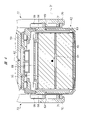
- a part of the arrangement area of the first arm 68 and a part of the arrangement area of the second arm 70 are the arrangement of the battery pack 62. Located within the area. Further, as shown in FIG. 2, the rotating shaft B1 is located within the arrangement region of the battery pack 62 in the axial direction of the rotating shaft B1.
- the center of gravity G1 of the battery pack 62 is located in the arrangement region E1 of the ten battery cells 65 in the axial direction of the rotation shaft B1. Further, in both the axial view of the rotating shaft B1 as shown in FIGS. 2 and 3 and the vertical view of the rotating shaft B1 and the center line A2 as shown in FIG. 4, the rotating shaft B1 and the center of gravity G1 are aligned with each other. Overlap. In other words, the rotation shaft B1 passes through the center of gravity G1.
- the phrase "the rotation axis B1 and the center of gravity G1 overlap" includes that the center of gravity G1 is located within the arrangement range of the protrusion 71 in the axial view of the rotation axis B1 shown in FIG. Therefore, it is possible to suppress an increase in the moment applied to the battery pack 62 around the rotation shaft B1, and it is possible to reliably suppress the vibration of the battery pack 62 with respect to the battery mounting portion 50.
- the hammer drill 10 of the second embodiment is shown in FIGS. 6, 7, and 8.
- the same configuration as that of the hammer drill 10 of the first embodiment is designated by the same reference numeral as that of the hammer drill 10 of the first embodiment.
- the hammer drill 10 of the second embodiment has a support mechanism 74 that makes the handle 16 rotatable with respect to the housing 11. Comparing the hammer drill 10 of the first embodiment and the hammer drill 10 of the second embodiment, the configuration of the support mechanism 73 and the configuration of the support mechanism 74 are different.
- the support mechanism 74 has a guide groove 75 and a protrusion 76.
- the guide groove 75 is provided in the housing 11, for example, the motor case 19.
- the guide groove 75 is an arc-shaped hole or recess provided around the rotation shaft B2.
- the protrusion 76 is provided on the battery mounting portion 50.
- the rotation axis B2 is a mechanical engineering virtual line or a rotation center, and the rotation axis B2 is not an object.
- the protrusion 76 is an arc-shaped rail or rib provided around the rotation shaft B2.
- the arrangement range of the protrusion 76 centered on the rotation shaft B2 is narrower than the arrangement range of the guide groove 75 centering on the rotation shaft B2.
- the guide groove 75 and the protrusion 76 are provided on the same virtual circle C1 centered on the rotation shaft B2 and at a position separated from the rotation shaft B2.
- the protrusion 76 is arranged in the guide groove 75, and the protrusion 76 can move in the guide groove 75 in an arc shape about the rotation shaft B1.
- the rotation shaft B2 is located outside the arrangement area of the housing 11 and outside the arrangement area of the battery mounting portion 50. For convenience, a part of the virtual circle C1 within a predetermined angle range is shown.
- the rotating shaft B2 is located in the arrangement area of the battery pack 62 with the battery pack 62 attached to the battery mounting portion 50. Further, the rotation shaft B2 is located in the arrangement region E1 with the battery pack 62 attached to the battery mounting portion 50. Further, with the battery pack 62 attached to the battery mounting portion 50, the rotation shaft B2 is provided at a position eccentric from the center of gravity G1 of the battery pack 62.
- the hammer drill 10 of the second embodiment when the handle 16 vibrates with respect to the housing 11, the protrusion 76 moves around the rotation shaft B2 in the guide groove 75. That is, the handle 16 is vibrated within a predetermined angle range about the rotation shaft B2. Further, the rotating shaft B2 is located within the arrangement region of the battery pack 62 in the vertical view with respect to the rotating shaft B2. Therefore, it is possible to suppress the battery pack 62 from vibrating with respect to the battery mounting portion 50. Therefore, the hammer drill 10 of the second embodiment can obtain the same effect as the hammer drill 10 of the first embodiment.
- the hammer drill 10 is an example of a working machine.
- the electric motor 12 is an example of a motor.
- the actuating portion 15 is an example of an actuating member.
- the housing 11 is an example of a housing.
- the handle 16 is an example of a handle.
- the battery pack 62 is an example of a battery pack.
- the connection portion 49 is an example of the first connection portion.
- the battery mounting unit 50 is an example of the second connection unit.
- the elastic member 56 is an example of an elastic member.
- FIG. 1, FIG. 2, FIG. 2, FIG. 3, FIG. 5, FIG. 6, FIG. 7, and FIG. 8 are examples of "axial orientation of the rotating shaft", respectively.
- the direction along the center line A1 or the direction parallel to the center line A1 is an example of the "operating direction of the operating member". That is, the center line A1 is a virtual line indicating the operating direction of the operating member.
- the direction along the center line A2 or the direction parallel to the center line A2 is an example of "a direction intersecting the operating direction of the operating member".
- the rotation shafts B1 and B2 are examples of rotation shafts, respectively.
- the center of gravity G1 is an example of the center of gravity of the battery pack.
- the first arm 68 is an example of the first element.
- the insertion hole 69 is an example of the insertion hole and the first engaging portion.
- the second arm 70 is an example of the second element.
- the protrusion 71 is an example of the second engaging portion.
- the guide groove 75 is an example of the first engaging portion.
- the protrusion 76 is an example of the second engaging portion.
- the guide rail 58 and the guide groove 72 are examples of the guide portion.
- the figure showing the hammer drill in the plane including the center lines A1 and A2 or in the plane parallel to the center lines A1 and A2 is an example of "front view of the hammer drill". Further, the figure showing the hammer drill in a plane including at least one of the center line A1 or the center line A2 and in a plane perpendicular to the rotation axis is an example of "axial view of the rotation axis".
- the working machine is not limited to the disclosed embodiment, and can be variously changed without departing from the gist thereof.
- the working machine applies a rotational force, a striking force in the direction along the center line, and a hammer drill that applies a rotational force around the center line to the tip tool, and a striking force in the direction along the center line to the tip tool.
- a hammer that does not apply a rotational force around the center line is included.
- the power conversion mechanism may be a cam mechanism instead of the crank mechanism.
- the electric motor may be either a brushless motor or a brushed motor.
- the axis of rotation may be either a mechanical engineering virtual line or an object as a solid.
- a protrusion, a cylinder, or a sleeve can be defined as a rotation axis.
- the rotation shaft as an object may be provided in the housing, and the handle may be provided with an insertion hole into which the rotation shaft as an object is inserted.
- the insertion hole into which the object as the rotation axis is inserted may be a through hole, a recess, or a groove.
- the housing may be configured as a casing, a body, or a working machine main body. Further, "centered on the rotating shaft” can be defined as "with the rotating shaft as a fulcrum".
- the working machine includes a virtual line in which the virtual line indicating the operating direction of the operating member intersects with the center line indicating the rotation center of the motor, or the virtual line and the center line are parallel to each other, or a virtual line. Any of those arranged concentrically with the center line may be used.
- the motor, the actuating member actuated by the motor, the housing supporting the motor and the actuating member, and the housing are rotatably connected to the housing via a support mechanism and gripped by an operator.
- a working machine having a handle and a battery pack attached to the handle, wherein the rotation axis of the support mechanism is viewed in a direction perpendicular to the operating direction of the operating member and the rotation center line of the motor. Located within the battery pack placement area. Further, the battery pack is attached to and detached from the handle along the operating direction of the operating member.
Landscapes
- Engineering & Computer Science (AREA)
- Mechanical Engineering (AREA)
- Percussive Tools And Related Accessories (AREA)
- Portable Power Tools In General (AREA)
Priority Applications (1)
| Application Number | Priority Date | Filing Date | Title |
|---|---|---|---|
| JP2022553709A JP7464139B2 (ja) | 2020-09-30 | 2021-09-03 | 作業機 |
Applications Claiming Priority (2)
| Application Number | Priority Date | Filing Date | Title |
|---|---|---|---|
| JP2020-164660 | 2020-09-30 | ||
| JP2020164660 | 2020-09-30 |
Publications (1)
| Publication Number | Publication Date |
|---|---|
| WO2022070763A1 true WO2022070763A1 (ja) | 2022-04-07 |
Family
ID=80950179
Family Applications (1)
| Application Number | Title | Priority Date | Filing Date |
|---|---|---|---|
| PCT/JP2021/032422 Ceased WO2022070763A1 (ja) | 2020-09-30 | 2021-09-03 | 作業機 |
Country Status (2)
| Country | Link |
|---|---|
| JP (1) | JP7464139B2 (https=) |
| WO (1) | WO2022070763A1 (https=) |
Citations (9)
| Publication number | Priority date | Publication date | Assignee | Title |
|---|---|---|---|---|
| US5950268A (en) * | 1997-12-02 | 1999-09-14 | Royal Appliance Mfg. Co. | Hand-held scrubbing device |
| JP2003260677A (ja) * | 2001-12-03 | 2003-09-16 | Milwaukee Electric Tool Corp | 往復動式のこぎりのハンドル装置 |
| WO2011105232A1 (ja) * | 2010-02-25 | 2011-09-01 | 株式会社マキタ | 動力工具 |
| JP2014231126A (ja) * | 2013-05-29 | 2014-12-11 | 株式会社マキタ | 往復動式作業工具 |
| JP2017001148A (ja) * | 2015-06-12 | 2017-01-05 | マックス株式会社 | 打撃工具 |
| WO2017002518A1 (ja) * | 2015-06-30 | 2017-01-05 | 日立工機株式会社 | 作業機 |
| US20170071134A1 (en) * | 2015-09-15 | 2017-03-16 | Chervon (Hk) Limited | Hedge trimmer |
| JP2019005848A (ja) * | 2017-06-23 | 2019-01-17 | 工機ホールディングス株式会社 | 動力工具 |
| JP2020040199A (ja) * | 2018-09-10 | 2020-03-19 | 株式会社マキタ | 打撃工具 |
-
2021
- 2021-09-03 WO PCT/JP2021/032422 patent/WO2022070763A1/ja not_active Ceased
- 2021-09-03 JP JP2022553709A patent/JP7464139B2/ja active Active
Patent Citations (9)
| Publication number | Priority date | Publication date | Assignee | Title |
|---|---|---|---|---|
| US5950268A (en) * | 1997-12-02 | 1999-09-14 | Royal Appliance Mfg. Co. | Hand-held scrubbing device |
| JP2003260677A (ja) * | 2001-12-03 | 2003-09-16 | Milwaukee Electric Tool Corp | 往復動式のこぎりのハンドル装置 |
| WO2011105232A1 (ja) * | 2010-02-25 | 2011-09-01 | 株式会社マキタ | 動力工具 |
| JP2014231126A (ja) * | 2013-05-29 | 2014-12-11 | 株式会社マキタ | 往復動式作業工具 |
| JP2017001148A (ja) * | 2015-06-12 | 2017-01-05 | マックス株式会社 | 打撃工具 |
| WO2017002518A1 (ja) * | 2015-06-30 | 2017-01-05 | 日立工機株式会社 | 作業機 |
| US20170071134A1 (en) * | 2015-09-15 | 2017-03-16 | Chervon (Hk) Limited | Hedge trimmer |
| JP2019005848A (ja) * | 2017-06-23 | 2019-01-17 | 工機ホールディングス株式会社 | 動力工具 |
| JP2020040199A (ja) * | 2018-09-10 | 2020-03-19 | 株式会社マキタ | 打撃工具 |
Also Published As
| Publication number | Publication date |
|---|---|
| JP7464139B2 (ja) | 2024-04-09 |
| JPWO2022070763A1 (https=) | 2022-04-07 |
Similar Documents
| Publication | Publication Date | Title |
|---|---|---|
| US10179400B2 (en) | Power tool | |
| JP6849088B2 (ja) | 電気機器 | |
| JP6278830B2 (ja) | 打撃工具 | |
| JPWO2018221105A1 (ja) | 往復動工具 | |
| US11471995B2 (en) | Oscillating electric power tool with balanced armature shaft | |
| WO2015145583A1 (ja) | 打撃工具 | |
| JP2015217470A (ja) | 打撃工具 | |
| CN112512737B (zh) | 动力工具 | |
| JP2022024097A (ja) | 打撃工具 | |
| JP6981803B2 (ja) | 打撃工具 | |
| JP2017001148A (ja) | 打撃工具 | |
| JP2007007832A (ja) | 電動工具 | |
| CN109693211B (zh) | 冲击工具 | |
| JP6429120B2 (ja) | インパクト回転工具 | |
| US11858100B2 (en) | Impact power tool | |
| JP2019209455A (ja) | 動力工具 | |
| WO2017110229A1 (ja) | 回転工具 | |
| JP7464139B2 (ja) | 作業機 | |
| US12172284B2 (en) | Power tool having hammer mechanism | |
| JP2013063494A (ja) | 電動工具 | |
| WO2017199823A1 (ja) | 打撃工具 | |
| EP4414135A1 (en) | Work machine | |
| JP7330009B2 (ja) | コンクリート型枠打撃用治具、及びコンクリート型枠打撃装置 | |
| JP4888329B2 (ja) | 往復動工具 | |
| JP7412135B2 (ja) | 打撃工具 |
Legal Events
| Date | Code | Title | Description |
|---|---|---|---|
| 121 | Ep: the epo has been informed by wipo that ep was designated in this application |
Ref document number: 21875065 Country of ref document: EP Kind code of ref document: A1 |
|
| ENP | Entry into the national phase |
Ref document number: 2022553709 Country of ref document: JP Kind code of ref document: A |
|
| NENP | Non-entry into the national phase |
Ref country code: DE |
|
| 122 | Ep: pct application non-entry in european phase |
Ref document number: 21875065 Country of ref document: EP Kind code of ref document: A1 |