WO2022070748A1 - 車両用センサ装置及び車両用灯具 - Google Patents
車両用センサ装置及び車両用灯具 Download PDFInfo
- Publication number
- WO2022070748A1 WO2022070748A1 PCT/JP2021/032169 JP2021032169W WO2022070748A1 WO 2022070748 A1 WO2022070748 A1 WO 2022070748A1 JP 2021032169 W JP2021032169 W JP 2021032169W WO 2022070748 A1 WO2022070748 A1 WO 2022070748A1
- Authority
- WO
- WIPO (PCT)
- Prior art keywords
- transmission region
- outer cover
- region
- generating member
- heat generating
- Prior art date
- Legal status (The legal status is an assumption and is not a legal conclusion. Google has not performed a legal analysis and makes no representation as to the accuracy of the status listed.)
- Ceased
Links
Images








Classifications
-
- F—MECHANICAL ENGINEERING; LIGHTING; HEATING; WEAPONS; BLASTING
- F21—LIGHTING
- F21S—NON-PORTABLE LIGHTING DEVICES; SYSTEMS THEREOF; VEHICLE LIGHTING DEVICES SPECIALLY ADAPTED FOR VEHICLE EXTERIORS
- F21S41/00—Illuminating devices specially adapted for vehicle exteriors, e.g. headlamps
- F21S41/20—Illuminating devices specially adapted for vehicle exteriors, e.g. headlamps characterised by refractors, transparent cover plates, light guides or filters
-
- F—MECHANICAL ENGINEERING; LIGHTING; HEATING; WEAPONS; BLASTING
- F21—LIGHTING
- F21S—NON-PORTABLE LIGHTING DEVICES; SYSTEMS THEREOF; VEHICLE LIGHTING DEVICES SPECIALLY ADAPTED FOR VEHICLE EXTERIORS
- F21S43/00—Signalling devices specially adapted for vehicle exteriors, e.g. brake lamps, direction indicator lights or reversing lights
- F21S43/20—Signalling devices specially adapted for vehicle exteriors, e.g. brake lamps, direction indicator lights or reversing lights characterised by refractors, transparent cover plates, light guides or filters
-
- F—MECHANICAL ENGINEERING; LIGHTING; HEATING; WEAPONS; BLASTING
- F21—LIGHTING
- F21S—NON-PORTABLE LIGHTING DEVICES; SYSTEMS THEREOF; VEHICLE LIGHTING DEVICES SPECIALLY ADAPTED FOR VEHICLE EXTERIORS
- F21S45/00—Arrangements within vehicle lighting devices specially adapted for vehicle exteriors, for purposes other than emission or distribution of light
- F21S45/60—Heating of lighting devices, e.g. for demisting
-
- F—MECHANICAL ENGINEERING; LIGHTING; HEATING; WEAPONS; BLASTING
- F21—LIGHTING
- F21V—FUNCTIONAL FEATURES OR DETAILS OF LIGHTING DEVICES OR SYSTEMS THEREOF; STRUCTURAL COMBINATIONS OF LIGHTING DEVICES WITH OTHER ARTICLES, NOT OTHERWISE PROVIDED FOR
- F21V29/00—Protecting lighting devices from thermal damage; Cooling or heating arrangements specially adapted for lighting devices or systems
- F21V29/90—Heating arrangements
-
- F—MECHANICAL ENGINEERING; LIGHTING; HEATING; WEAPONS; BLASTING
- F21—LIGHTING
- F21V—FUNCTIONAL FEATURES OR DETAILS OF LIGHTING DEVICES OR SYSTEMS THEREOF; STRUCTURAL COMBINATIONS OF LIGHTING DEVICES WITH OTHER ARTICLES, NOT OTHERWISE PROVIDED FOR
- F21V5/00—Refractors for light sources
-
- G—PHYSICS
- G01—MEASURING; TESTING
- G01S—RADIO DIRECTION-FINDING; RADIO NAVIGATION; DETERMINING DISTANCE OR VELOCITY BY USE OF RADIO WAVES; LOCATING OR PRESENCE-DETECTING BY USE OF THE REFLECTION OR RERADIATION OF RADIO WAVES; ANALOGOUS ARRANGEMENTS USING OTHER WAVES
- G01S13/00—Systems using the reflection or reradiation of radio waves, e.g. radar systems; Analogous systems using reflection or reradiation of waves whose nature or wavelength is irrelevant or unspecified
- G01S13/88—Radar or analogous systems specially adapted for specific applications
- G01S13/93—Radar or analogous systems specially adapted for specific applications for anti-collision purposes
- G01S13/931—Radar or analogous systems specially adapted for specific applications for anti-collision purposes of land vehicles
-
- G—PHYSICS
- G01—MEASURING; TESTING
- G01S—RADIO DIRECTION-FINDING; RADIO NAVIGATION; DETERMINING DISTANCE OR VELOCITY BY USE OF RADIO WAVES; LOCATING OR PRESENCE-DETECTING BY USE OF THE REFLECTION OR RERADIATION OF RADIO WAVES; ANALOGOUS ARRANGEMENTS USING OTHER WAVES
- G01S7/00—Details of systems according to groups G01S13/00, G01S15/00, G01S17/00
- G01S7/02—Details of systems according to groups G01S13/00, G01S15/00, G01S17/00 of systems according to group G01S13/00
- G01S7/03—Details of HF subsystems specially adapted therefor, e.g. common to transmitter and receiver
Definitions
- the present invention relates to a vehicle sensor device and a vehicle lamp equipped with the vehicle sensor device.
- a vehicle sensor device that is mounted inside a lamp cover of a vehicle and detects an object outside the vehicle using electromagnetic waves is known.
- the electromagnetic wave transmitted from the sensor is reflected by the ice and snow, which may affect the detection accuracy.
- the vehicle sensor device described in the following Patent Document 1 is known as a vehicle sensor device capable of reducing the influence of such ice and snow.
- the vehicle sensor device described in Patent Document 1 is arranged inside a lamp cover, and includes a sensor that transmits / receives electromagnetic waves to the outside of the vehicle and a separator that partitions a space in which the sensor is arranged.
- it is determined whether or not ice and snow are attached to the lamp cover based on the change in the behavior of the reflected wave power of the electromagnetic wave transmitted from the sensor, and the ice and snow are attached. When it is determined that the lamp cover is turned on, the light source in the lamp cover is turned on.
- the radiant heat from the light source is conducted to the lamp cover via the separator, and the ice and snow adhering to the lamp cover are melted, so that it is possible to suppress the influence on the detection accuracy of the sensor. Will be done.
- Patent Document 2 describes a vehicle lamp in which a heating element that generates heat when energized is attached to a lamp cover. According to the vehicle lighting equipment of Patent Document 2, since the lamp cover can be directly heated by the heating element that generates heat by energization, it is expected that the efficiency of removing ice and snow will be improved.
- an object of the present invention is to provide a vehicle sensor device capable of suppressing a decrease in detection accuracy and a vehicle lamp equipped with the vehicle sensor device.
- the vehicle sensor device is arranged inside the vehicle with respect to the outer cover and the outer cover, and transmits / receives a predetermined electromagnetic wave transmitted through the outer cover.
- a sensor unit that outputs a signal related to the electromagnetic wave incident on the inside of the outer cover and a transmission region of the outer cover through which the electromagnetic wave transmitted from the sensor unit is transmitted are heated by energization.
- the heat-generating member is provided with a heat-generating member, and the heat-generating member is attached to the outer cover so that the inside of the transmission region is sparser than the outside of the transmission region.
- the heat generating member for heating the transmission region is attached to the outer cover, as compared with the case where the outer cover is heated by heat conduction of radiant heat from the light source as in Patent Document 1, for example. Therefore, the outer cover can be directly heated, and the ice and snow adhering to the outer cover can be effectively melted. Further, according to this vehicle sensor device, since the heat generating member is attached so that the inside of the transmission region is sparser than the outside of the transmission region, the electromagnetic wave transmitted from the sensor unit is reflected by the heat generation member. Therefore, it can be suppressed to become noise. As described above, according to this vehicle sensor device, since it is possible to effectively remove ice and snow while suppressing the reflection of electromagnetic waves by the heat generating member, it is possible to suppress a decrease in detection accuracy.
- the heat generating member may not be arranged inside the transmission region.
- the reflection of electromagnetic waves by the heat generating member can be suppressed more effectively.
- the heat generating member is arranged outside the permeation region, ice and snow adhering to the permeation region can be effectively melted by the heat from the heat generating member.
- the vehicle sensor device operates the sensor unit so as to scan the electromagnetic wave along a predetermined direction, reflects the electromagnetic wave by a predetermined object, and receives the electromagnetic wave received by the sensor unit.
- a control unit for calculating the position of the object based on the above is further provided, and the heat generating member inside the transmission region is centered on the outer edge side of the transmission region in a direction perpendicular to the predetermined direction in the transmission region. It may be attached to the outer cover so that the side is sparser.
- an object to be detected is generally irradiated with electromagnetic waves transmitted and received through a region on the center side of a transmission region in a direction perpendicular to the direction in which electromagnetic waves are scanned. It is an object. Therefore, by attaching a heat generating member inside the transmission region so that the center side of the transmission region in the vertical direction becomes sparse, it is possible to suppress the reflection of electromagnetic waves on the center side of the transmission region to become noise, and detect it. It is possible to suppress a decrease in the detection accuracy of the target object. Further, by arranging the heat generating member so that the outer edge side of the transmission region in the vertical direction becomes dense inside the transmission region, the transmission region can be heated more effectively and adheres to the transmission region. It can effectively melt ice and snow.
- the heat generating member may be attached to the outer cover so as to surround the entire circumference of the transmission region.
- the permeation region can be effectively warmed as compared with the case where the heat generating member is attached to a part of the entire circumference of the permeation region, and the efficiency of removing ice and snow can be improved.
- the heat generating member may be attached only to a region of the outer cover that is vertically lower than the center of the transmission region.
- the ice and snow attached to the lower side of the permeation area can be melted first. After that, the ice and snow remaining on the upper side of the permeation region can fall and melt in the lower region from which the ice and snow have been removed. Therefore, even when the heat generating member is attached only to the lower region in this way, ice and snow can be effectively removed. Further, since the heat generating member can be reduced as compared with the case where the heat generating member is attached to the entire periphery of the transmission region, the cost can be reduced.
- the heat generating member may be in the form of a mesh.
- the mesh shape means a shape that divides a predetermined region into a plurality of sections, such as a net shape, a grid shape, or a porous shape. If the heat-generating member has such a mesh shape, a plurality of sections surrounded by the heat-generating member are formed in the outer cover. Then, each of the compartments can be heated from the entire circumference by the heat generating member surrounding these compartments. Therefore, the outer cover can be heated more effectively, and the efficiency of removing ice and snow can be improved.
- the vehicle lighting fixture of the present invention is arranged inside the vehicle with respect to the vehicle sensor device according to the first aspect according to any one of the above and the outer cover, and the outer cover is provided.
- a lamp unit that emits light to the outside of the vehicle via the It is characterized in that it is attached to the outer cover so that the inside of the light emitting region is sparser.
- this vehicle lamp is provided with the vehicle sensor device according to the first aspect described in any of the above, it is possible to suppress a decrease in detection accuracy. Further, in this vehicle lamp, since the heat generating member is attached so as to heat the light emitting region, ice and snow adhering to the light emitting region can be removed. Further, since the heat generating member is sparser inside the light emitting region than outside the light emitting region, the light emitted from the lamp unit is suppressed from being reflected by the heat generating member inside the light emitting region. It is possible to suppress a decrease in the emission efficiency of light from the lamp unit.
- the vehicle sensor device is arranged inside the vehicle with respect to the outer cover and the outer cover, and transmits / receives a predetermined electromagnetic wave transmitted through the outer cover.
- the sensor unit that outputs a signal related to the electromagnetic wave incident on the inside of the outer cover and the sensor unit are operated so as to scan the electromagnetic wave along a predetermined direction, and are reflected by a predetermined object to be reflected by the sensor unit.
- a control unit that calculates the position of the object based on the electromagnetic wave received in the above, and a heat generating member that is attached to the outer cover and heats a transmission region of the outer cover through which the electromagnetic wave is transmitted by energization.
- the heat generating member is characterized in that a part of the inside of the transmission region extends along the predetermined direction and crosses the transmission region.
- the heat generating member for heating the transmission region is attached to the outer cover, as compared with the case where the outer cover is heated by heat conduction of radiant heat from the light source as in Patent Document 1, for example. Therefore, the outer cover can be directly heated, and the ice and snow adhering to the outer cover can be effectively melted. Further, since the heat generating member crosses the inside of the transmission region, the transmission region is heated over the entire length of the transmission region in the predetermined direction, and the transmission region can be effectively warmed. Therefore, the ice and snow adhering to the permeation region can be effectively melted.
- the heat generating member inside the transmission region extends in a direction intersecting the predetermined direction
- the electromagnetic wave to be scanned is reflected by the heat generating member and the intensity of the electromagnetic wave received by the sensor unit in the predetermined direction is high.
- the distribution may change, leading to a decrease in detection accuracy.
- the heat generating member crosses a part of the inside of the transmission region along the predetermined direction. Therefore, the change in the intensity distribution of the electromagnetic wave received by the sensor unit in the predetermined direction is suppressed, and the deterioration of the detection accuracy can be suppressed.
- this vehicle sensor device since it is possible to effectively remove ice and snow while suppressing the influence of the reflection of electromagnetic waves by the heat generating member, it is possible to suppress the deterioration of the detection accuracy.
- the heat generating member inside the transmission region in the direction perpendicular to the predetermined direction in the transmission region, is closer to the center side than the outer edge side of the transmission region. It may be attached to the outer cover so as to be sparse.
- the heat generating member is provided so that the center side of the transmission region in the vertical direction becomes sparse inside the transmission region. By attaching it, it is possible to suppress the reflection of electromagnetic waves on the center side of the transmission region to become noise, and it is possible to suppress the deterioration of the detection accuracy of the object to be detected. Further, by arranging the heat generating member so that the outer edge side of the transmission region in the vertical direction becomes dense inside the transmission region, the transmission region can be heated more effectively and adheres to the transmission region. It can effectively melt ice and snow.
- the heat generating member may be attached to the outer cover so that the inside of the transmission region is sparser than the outside of the transmission region.
- the heat generating member may be attached to the outer cover so as to surround the entire circumference of the transmission region.
- the transmission area is more effective than the case where the heat generating member is attached to a part of the entire circumference of the transmission area. It can be warmed up and the efficiency of removing ice and snow can be improved.
- the heat generating member may be attached only to a region of the outer cover that is vertically lower than the center of the transmission region.
- the vehicle sensor device according to the second aspect can effectively remove ice and snow, etc., as compared with the case where the heat generating member is attached to the entire circumference of the transmission region. Since the number of heat generating members can be reduced, the cost can be reduced.
- the vehicle lighting fixture of the present invention is arranged inside the vehicle with respect to the vehicle sensor device according to the second aspect according to any one of the above and the outer cover, and the outer cover is provided.
- a lamp unit that emits light to the outside of the vehicle via the vehicle, and at least a part of the heat generating member inside the transmission region is the outer side of the transmission region along the predetermined direction. It is characterized in that it extends to the light emitting region of the cover from which the light is emitted.
- this vehicle lamp is provided with the vehicle sensor device according to the second aspect described in any of the above, it is possible to suppress a decrease in detection accuracy. Further, in this vehicle lamp, since the heat generating member is attached so as to heat the light emitting region, ice and snow adhering to the light emitting region can be removed. Further, in this vehicle lamp, since the heat generating member inside the transmission region extends to the light emission region along a predetermined direction, the light emission region can be heated by the heat generation member that heats the transmission region. Therefore, it is not necessary to separately provide a heat generating member for heating the light emitting region, and the wiring cost can be reduced.
- a vehicle sensor device capable of suppressing a decrease in detection accuracy and a vehicle lamp equipped with the vehicle sensor device.
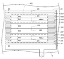
- FIG. 1 It is a figure which shows mainly the vicinity of a transmission region and the vicinity of a light emission region of the heater according to the fourth embodiment of the present invention from the same viewpoint as in FIG. It is a figure which shows the modification of the wiring pattern of the heating wire of FIG. It is a figure which shows the heater which concerns on 5th Embodiment of this invention from the same viewpoint as FIG. It is a figure which shows the modification of the wiring pattern of the heating wire of FIG. It is a figure which shows the 2nd modification of the wiring pattern of the heating wire of FIG. It is a figure which shows the modification of the wiring pattern of the heating wire of FIG. It is a figure which shows the heater which concerns on the modification of 1st Embodiment of this invention from the same viewpoint as FIG. It is a figure which shows the heater which concerns on the modification of 2nd Embodiment of this invention from the same viewpoint as FIG.
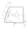
- FIG. 1 is a front view showing an outline of a vehicle and a vehicle lighting fixture provided with a vehicle sensor device according to the first embodiment of the present invention.
- the vehicle lighting fixture VL of the present embodiment is a vehicle headlight of the vehicle VE, and includes a vehicle sensor device 1 and a lighting fixture unit LU as a main configuration.
- the vehicle sensor device 1 and the lamp unit LU are substantially arranged along the left-right direction.
- the front means the traveling direction of the vehicle VE, and the left and right mean the left side and the right side with respect to the traveling direction.
- the lamp unit LU is arranged inside the vehicle VE with respect to the outer cover 12 described later, and emits light to the outside of the vehicle VE through the outer cover 12. As shown by the broken line in FIG. 1, the light emitted from the lamp unit LU passes through the light emission region LR of the outer cover 12 and is emitted in front of the vehicle VE.
- FIG. 2 is a diagram showing an outline of a cross section of the vehicle sensor device 1 on the line II-II shown in FIG.
- the vehicle sensor device 1 includes a housing 10, a sensor unit 20, a heater 30, and a control unit CO as main configurations. In FIG. 1, the heater 30 and the control unit CO are not shown.
- the control unit CO is connected to the sensor unit 20 and the heater 30.
- the control unit CO is composed of, for example, an integrated circuit such as a microcontroller, an IC (Integrated Circuit), an LSI (Large-scale Integrated Circuit), an ASIC (Application Specific Integrated Circuit), or an NC (Numerical Control) device. Further, when an NC device is used, these may be those using a machine learning device or those not using a machine learning device.
- the control unit CO may be unique to the vehicle sensor device 1, or at least a part of the control unit CO may be included in the ECU (Electronic Control Unit) of the vehicle VE.
- the housing 10 of the present embodiment includes the housing 11 and the outer cover 12 as the main configurations.
- the outer cover 12 is made of a material that transmits light emitted from the lamp unit LU and electromagnetic waves transmitted and received from the sensor unit 20 described later. Examples of the material for forming such an outer cover 12 include a resin such as polycarbonate.
- the housing 11 is configured in a box shape having an opening in the front, and the outer cover 12 is fixed to the housing 11 so as to close the opening. As shown in FIG. 2, the outer cover 12 extends substantially along the vertical direction.
- the housing 11 may be made of a material different from that of the outer cover 12, or may be made of the same material.
- a housing space 13 surrounded by the housing 11 and the outer cover 12 is formed in the housing 10, and the sensor unit 20 and the lamp unit LU are arranged in the housing space 13.
- the sensor unit 20 of this embodiment is a millimeter wave radar that transmits and receives millimeter waves as the above electromagnetic waves.
- FIG. 3 is a diagram showing an outline of the sensor unit 20 viewed forward. As shown in FIG. 3, the sensor unit 20 includes a transmitting antenna 25 and a plurality of receiving antennas 26. The control unit CO is connected to the transmitting antenna 25 and each receiving antenna 26. Although three receiving antennas 26 are shown in FIG. 3, there may be two or four or more receiving antennas 26.
- the transmitting antenna 25 transmits the millimeter wave EW forward. Therefore, the millimeter wave EW passes through a predetermined region of the outer cover 12 and propagates toward the front outside the vehicle.
- the millimeter wave EW is emitted from the transmitting antenna 25 so that the spread in the left-right direction is larger than the spread in the vertical direction. Therefore, as shown by the broken line in FIG. 1, the transmission region AR transmitted by the millimeter wave EW transmitted from the sensor unit 20 in the outer cover 12 is a substantially rectangular shape flat in the left-right direction.
- the transmitting antenna 25 uses a control signal from the control unit CO to make the millimeter wave EW a millimeter wave whose intensity is substantially constant and whose frequency repeatedly increases and decreases in a predetermined cycle.
- the millimeter wave EW passes through the transmission region AR and is emitted to the outside of the vehicle, it spreads largely in the left-right direction as compared with the vertical direction, and a detectable region FA by the millimeter wave EW is formed.
- the detectable region FA is a substantially rectangular shape that is flat in the left-right direction in the forward view, and is a substantially fan shape that is wider toward the front side in the upward view.
- the detectable area FA is also referred to as a FOV area.
- the millimeter wave EW is reflected by the object, and a part of the reflected millimeter wave EW passes through the transmission region AR and is incident on the accommodation space 13.
- the millimeter wave EW reflected by the object may be incident on the accommodation space 13 from other than the transmission region AR in the outer cover 12 when the position of the receiving antenna 26 and the position of the transmitting antenna 25 are separated from each other.
- each of the plurality of receiving antennas 26 has substantially the same configuration. As shown in FIG. 3, each of these receiving antennas 26 and the transmitting antenna 25 are arranged side by side at predetermined intervals along the left-right direction. Further, the center of the receiving antenna 26 in the vertical direction and the center of the transmitting antenna 25 in the vertical direction are generally located on a straight line extending in the left-right direction. Each of the receiving antennas 26 has, for example, a configuration in which a plurality of patch antennas are overlapped in the vertical direction. Each of the receiving antennas 26 receives the millimeter wave EW reflected by the object and incident on the accommodation space 13.
- each of the receiving antennas 26 outputs a signal indicating the waveform of the millimeter wave EW as a signal related to the received millimeter wave EW to the control unit CO.
- the strength of the electromagnetic wave received by the receiving antenna 26 is included as an element forming the waveform of the electromagnetic wave.
- the control unit CO When the signal related to the millimeter wave EW is input from each receiving antenna 26, the control unit CO is based on, for example, the signal related to the received millimeter wave EW and the signal indicating the waveform of the electromagnetic wave emitted from the transmitting antenna 25, for example.
- the distance from the vehicle VE to the object is calculated by the FMCW (Frequency Modified Continuous Wave) method.
- the plurality of receiving antennas 26 are provided at intervals in the left-right direction, a phase difference occurs in the millimeter wave EW reflected by the object and received by each receiving antenna 26. Based on this phase difference, the control unit CO is left and right with respect to the reference line SL in which the object OB in the detectable region FA shown in FIG.
- a predetermined direction for scanning an electromagnetic wave corresponds to a direction in which a plurality of receiving antennas are arranged in parallel, and is a left-right direction in the present embodiment. Therefore, in the present embodiment, the direction perpendicular to the predetermined direction for scanning the electromagnetic wave is generally the vertical direction.
- the scanning method of the sensor unit 20 is not limited to the electronic scanning method.
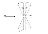
- one receiving antenna 26 may be rotated about the axis Ax extending in the vertical direction to change the angle of the receiving antenna 26 with respect to the left-right direction.
- FIG. 5 is a view of the one receiving antenna 26 viewed upward.
- the electromagnetic wave received by one receiving antenna 26 has a phase difference depending on the angle ⁇ of the receiving antenna 26. Therefore, the control unit CO calculates, for example, whether the object OB in the detectable region FA is unevenly distributed to the left or right with respect to the reference line SL at an angle ⁇ based on this phase difference. Can be done.
- the method of calculating the position of an object in the detectable region based on the phase difference of the electromagnetic wave generated by mechanically changing the direction of the receiving antenna in this way is called the mechanical scan method.
- the predetermined direction for scanning the electromagnetic wave corresponds to the direction in which the angle ⁇ of the receiving antenna is defined, and is the left-right direction in the present embodiment. Therefore, in the present embodiment, the direction perpendicular to the predetermined direction for scanning the electromagnetic wave is generally the vertical direction.
- the sensor unit 20 may be configured to emit a pulsed electromagnetic wave while the transmitting antenna 25 rotates about the axis extending in the vertical direction, for example.
- the direction of scanning the electromagnetic wave can be set to the left-right direction by rotating the transmitting antenna 25 about the axis extending in the vertical direction in this way.
- the control unit CO calculates the position of the object OB by, for example, the ToF (Time of Flight) method.
- control unit CO of the present embodiment operates the sensor unit 20 so as to scan the millimeter wave, which is an electromagnetic wave, along a predetermined direction, and the electromagnetic wave reflected by the object OB and received by the sensor unit 20.
- the position of the object OB is calculated based on.
- the heater 30 includes a plurality of heating wires 31 as heat generating members.
- Each of the heating wires 31 is attached to the inside of the transmission region AR and its vicinity on the inner surface 12i of the outer cover 12.
- the heat generating member may be attached to the entire inner surface 12i outside the transmission region AR.
- Each of the heating wires 31 is connected to the power supply circuit 32 via the connector 33.
- the power supply circuit 32 supplies a current from a power source (not shown) to each of the heating wires 31 by a control signal from the control unit CO.
- a control signal from the control unit CO As a result, each of the heating wires 31 is heated to a predetermined temperature by the electric resistance to energization, and as a result, at least the transmission region AR is heated.
- Such a heating wire 31 is formed on the inner surface 12i by, for example, applying or printing a conductive paste such as silver paste, gold paste, copper paste, aluminum paste, ITO paste on the inner surface 12i, or by using a predetermined adhesive. It may be attached. Alternatively, the heating wire 31 may be attached to the outer cover 12 with a metal wire attached to the outer cover 12 by a hot cloth wire or the like.
- the hot cloth wire means that heat is applied to the base material on which the heating wire is provided to soften the base material, and the metal wire is applied to the softened base material to be embedded in the base material. Therefore, in the case of using a hot cloth wire, at least a part of the heat generating member can be attached to the inside of the outer cover 12.
- the position where the heat generating member is attached may be the outer surface 12o of the outer cover 12.
- the heat generating member may be attached to the inner surface 12i of the outer cover 12 or the inside of the outer cover, it is possible to prevent ice, snow, dirt, etc. from adhering to the heat generating member.
- the heat generating member may be attached to at least the region for heating the transmission region AR, and may or may not be attached to, for example, the light emitting region LR in the region where it can be heated.
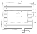
- FIG. 6 is a diagram showing a state mainly in the vicinity of the transmission region AR of the heater 30 in the present embodiment.
- the plurality of heating wires 31 extend along the left-right direction, which is the direction in which the electromagnetic wave is scanned, and surround the entire circumference of the transmission region AR indicated by the broken line.
- the heat generating member of the present embodiment is attached so as to surround the entire circumference of the transmission region AR.
- the addition of a reference numeral to a part of the heating wire 31 is omitted in this figure and the following figures.
- the plurality of heating wires 31 have the same thickness, and the distance between the heating wires 31 adjacent to each other outside the transmission region AR is the same D1.
- the addition of a reference numeral to a part of the interval D1 of the heating wire 31 is omitted in this figure and the following figures.
- each of the heating wires 31A, 31B, 31C, and 31D crosses a part of the inside of the transmission region AR. Inside the transmission region AR, the intervals between the heating wires 31A and 31B, the intervals between the heating wires 31B and 31C, and the intervals between the heating wires 31C and 31D are the same D2, respectively.
- the interval D2 is wider than the interval D1 and, in the present embodiment, is approximately three times the interval D1.
- FIG. 7 is a diagram showing a modified example of the wiring pattern of the heating wire 31 described with reference to FIG. 6, and the same reference numerals are used for the same configurations as those described with reference to FIG. 6, and the description thereof will be omitted.
- the heating wires 31 are formed in series, the heating wires 31 are not branched at least in and around the transmission region AR, and the arrangement of the heating wires 31 in the transmission region AR is the transmission region in FIG. It is the same as the arrangement of the heating wire 31 in AR.
- a plurality of unit region SRs having the same area are defined inside the transmission region AR and outside the transmission region AR, respectively.
- one unit region SR inside and one outside the transmission region AR is exemplified by a alternate long and short dash line.
- approximately one heating wire 31 crosses each unit region SR inside the transmission region AR, and approximately three unit region SRs outside the transmission region AR. The heating wire 31 crosses.
- the average ratio of the heat generating member to each unit region SR inside the transmission region AR is outside the transmission region AR. It is smaller than the average of the ratio of the heat generating member to each unit area SR in.
- the heat generating member is attached to the outer cover 12 so that the inside of the transmission region AR is sparser than the outside of the transmission region AR.
- the above ratio may be referred to as density.
- the vehicle sensor device 1 of the present embodiment can be grasped as follows as the first aspect. That is, the vehicle sensor device 1 of the present embodiment is arranged inside the outer cover 12 and the vehicle VE with respect to the outer cover 12, and transmits / receives millimeter wave EW transmitted through the outer cover 12 to the inside of the outer cover 12. Heat generation that heats the transmission region AR that is attached to the outer cover 12 and transmits the millimeter wave EW transmitted from the sensor unit 20 of the outer cover 12 and the sensor unit 20 that outputs the signal related to the incident millimeter wave EW. A plurality of heating wires 31 which are members are provided, and the heat generating member is attached to the outer cover 12 so that the inside of the transmission region AR is sparser than the outside of the transmission region AR.
- the vehicle sensor device 1 of the first aspect since a plurality of heating wires 31 for heating the transmission region AR by energization are attached to the outer cover 12 as heat generating members, for example, from the lighting unit LU. Compared with the case where the outer cover 12 is heated by utilizing the heat conduction of radiant heat, the outer cover 12 can be directly heated, and the ice and snow adhering to the outer cover 12 can be effectively melted. Further, according to the vehicle sensor device 1, the heat generating member is attached so that the inside of the transmission region AR is sparser than the outside of the transmission region AR, and occupies the region inside the transmission region AR.
- the ratio of the heat generating member is small, it is possible to suppress that millimeter waves are reflected by the heat generating member and become noise. Further, in the present embodiment, since the heat generating member is also attached to the inside of the transmission region AR, the ice and snow adhering to the inside of the transmission region AR is more effective than the case where the heat generating member is not arranged inside the transmission region AR. Can be removed. As described above, according to the vehicle sensor device 1 grasped as the first aspect, since it is possible to effectively remove ice and snow while suppressing the reflection of millimeter waves by the heat generating member, it is possible to suppress the deterioration of the detection accuracy. ..
- the vehicle sensor device 1 of the present embodiment can be grasped as follows as the second aspect. That is, the vehicle sensor device 1 of the present embodiment is arranged inside the vehicle VE with respect to the outer cover 12 and the outer cover 12, and transmits / receives millimeter wave EW, which is a predetermined electromagnetic wave transmitted through the outer cover 12, to the outer.
- the sensor unit 20 that outputs a signal related to the millimeter wave EW incident on the inside of the cover 12 and the sensor unit 20 are operated so as to scan the millimeter wave EW along the left and right directions that are predetermined directions, and the sensor unit 20 is operated with a predetermined object.
- the control unit CO that reflects and calculates the position of the object based on the millimeter wave EW received by the sensor unit 20 and the transmission region AR that is attached to the outer cover 12 and through which the millimeter wave EW passes is energized.
- a plurality of heating wires 31 which are heat generating members to be heated by the above are provided, and the heat generating member extends a part of the inside of the transmission region AR along a predetermined direction and crosses the transmission region AR.
- the transmission region AR is heated over the entire length of the transmission region AR in the left-right direction, and the transmission region AR is heated. Can be effectively warmed. Therefore, the ice and snow adhering to the transmission region AR can be effectively melted.
- the heat generating member inside the transmission region AR extends in a direction intersecting the left-right direction in which the electromagnetic wave is scanned, the scanned electromagnetic wave is reflected by the heat generating member, and the intensity distribution of the received electromagnetic wave in the left-right direction is increased. It changes and can lead to a decrease in detection accuracy.
- the heat generating member crosses the inside of the transmission region AR along the left-right direction. Therefore, the change in the intensity distribution of the electromagnetic wave received by the sensor unit 20 in the left-right direction is suppressed, and the deterioration of the detection accuracy can be suppressed.
- the vehicle sensor device 1 grasped as the second aspect since it is possible to effectively remove ice and snow while suppressing the influence of the reflection of millimeter waves by the heat generating member, the deterioration of the detection accuracy is suppressed. Can be.
- the predetermined direction for scanning the electromagnetic wave is the left-right direction.
- the object to be detected is generally a moving object such as another vehicle or a pedestrian.
- such a moving body is easily detected by scanning an electromagnetic wave in the left-right direction or the front-back direction. Therefore, as described above, when the predetermined direction is the left-right direction, other vehicles, pedestrians, and the like can be effectively detected.
- the outer cover 12 of the vehicle sensor device attached to the vehicle extends substantially along the vertical direction as described above, so that when the predetermined direction is the left-right direction, the outer cover 12 extends in the predetermined direction.
- the vertical direction is generally the vertical direction.
- the heat generating member is densely attached to the outside of the transmission region AR, so that the ice and snow adhering to the upper side or the lower side of the transmission region AR are effectively removed.
- the weight of the ice and snow promotes the fall of the ice and snow, which can increase the efficiency of removing the ice and snow.
- the heat generating member is attached to the outer cover 12 so as to surround the entire circumference of the transmission region AR.
- the transmission region AR can be effectively warmed and the efficiency of removing ice and snow can be improved, as compared with the case where the heat generating member is attached to a part of the entire circumference of the transmission region AR.
- the vehicle sensor device 1 according to the present embodiment has the same configuration as the vehicle sensor device 1 according to the first embodiment except that the configuration of the heater is different. Therefore, only the heater according to this embodiment will be described.
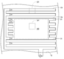
- FIG. 8 is a diagram showing the heater according to the present embodiment from the same viewpoint as in FIG.
- the heat generating member of the heater of the present embodiment is a plurality of heating wires 31 extending in the left-right direction as in the first embodiment, but the heat generating member is inside the transmission region AR.
- a heating wire 31 is non-arranged.
- the heating wire 31P extending substantially perpendicular to the direction in which these heating wires 31 extend to each of the ends of the heating wire 31 on the transmission region AR side that does not cross the inside of the transmission region AR. Is connected. In this way, in the present embodiment, all the heating wires 31 are conducted by connecting some of the heating wires in parallel.
- the wiring pattern for conducting all the heating wires is not limited to this.
- FIG. 9 is a diagram showing a modified example of the wiring pattern of the heating wire 31 described with reference to FIG. 8, and description thereof will be omitted by using the same reference numerals for the same configurations as those described with reference to FIG.
- the heating wire 31 is not arranged in the transmission region AR as in the heating wire 31 of FIG. Therefore, the vehicle sensor device 1 of the present embodiment does not correspond to the second aspect, but corresponds only to the first aspect. Further, the heating wire 31 similar to the heating wire 31 of FIG. 8 is formed in series, and the heating wire 31 is not branched at least around the transmission region AR.
- the heating wire 31 By attaching the heating wire 31 in this way, the current flowing through the heating wire 31 becomes constant regardless of the portion of the heating wire 31, and when the resistance value of the heating wire 31 is constant, the amount of heat generated in the heating wire 31 is unevenly distributed. It can be suppressed.
- the average ratio of the heat generating member to each unit region SR of the outer cover 12 inside the transmission region AR is zero.
- the average ratio of the heat generating member to each unit region SR inside the transmission region AR is the transmission region AR. It is smaller than the average of the ratio of the heat-generating member to each unit area SR on the outside of. Therefore, in the present embodiment, the heat generating member is attached to the outer cover 12 so that the inside of the transmission region AR is sparser than the outside of the transmission region AR.
- the vehicle sensor device 1 of the present embodiment suppresses the reflection of millimeter waves by the heat generating member while suppressing ice and snow, etc., as in the case of grasping the vehicle sensor device 1 of the first embodiment in the first aspect. Since it can be effectively removed, it is possible to suppress a decrease in detection accuracy.
- the heating wire 31 which is a heat generating member does not cross the transmission region AR. Therefore, the vehicle sensor device 1 of the present embodiment corresponds only to the first aspect and does not correspond to the second aspect.
- the predetermined direction for scanning the electromagnetic wave is the left-right direction, it is easy to detect the moving object, and the direction perpendicular to the predetermined direction is generally the vertical direction. , The efficiency of removing ice and snow can be increased.
- the heat generating member since the heat generating member is not arranged inside the transmission region AR, the reflection of the electromagnetic wave by the heat generating member can be suppressed more effectively. On the other hand, since the heat generating member is arranged outside the transmission region AR, the ice and snow adhering to the transmission region AR can be effectively melted by the heat from the heat generating member.
- the vehicle sensor device 1 according to the present embodiment has the same configuration as the vehicle sensor device 1 according to the first embodiment except that the configuration of the heater is different. Therefore, only the heater according to this embodiment will be described.
- FIG. 10 is a diagram showing the heater according to the present embodiment from the same viewpoint as in FIG.
- the heat generating member of the heater of the present embodiment is a plurality of heating wires 31 having the same thickness as in the first embodiment.
- a plurality of heating wires 31 are attached to the outer cover 12 in the following arrangement.
- each of the plurality of heating wires 31 which are heat generating members extends along the left-right direction which is the direction in which the electromagnetic wave is scanned. Further, on the outside of the transmission region AR, the distance between the heating wires 31 adjacent to each other is the same D1.
- each of the heating wires 31A to 31I crosses a part of the inside of the transmission region AR. Further, of these heating wires 31A to 31I, the heating wires 31A to 31C cross the upper region ARou inside the transmission region AR, respectively, and the heating wires 31G to 31I cross the lower region ARod inside the transmission region AR, respectively.
- the heat rays 31D to 31F cross the central region ARi sandwiched between the upper region ARou and the lower region ARod, respectively.
- Each of the heating wires 31 located between the heating wires 31A to 31I is connected to a heating wire extending substantially in the vertical direction along the outer edge of the transmission region AR. In this way, in the present embodiment, all the heating wires 31 are conducted by connecting some of the heating wires in parallel.
- the wiring pattern for conducting all the heating wires is not limited to this.
- FIG. 11 is a diagram showing a modified example of the wiring pattern of the heating wire 31 described with reference to FIG. 10, and the same reference numerals are used for the same configurations as those described with reference to FIG. 10, and the description thereof will be omitted.
- the heating wire 31 similar to the heating wire 31 of FIG. 10 is formed in series, and the heating wire 31 is not branched at least in the transmission region AR and its surroundings, and the heating wire 31 in the transmission region AR is not branched.
- the arrangement is the same as the arrangement of the heating wire 31 in the transmission region AR in FIG.
- the heating wire 31 By attaching the heating wire 31 in this way, the current flowing through the heating wire 31 becomes constant regardless of the portion of the heating wire 31, and when the resistance value of the heating wire 31 is constant, the amount of heat generated in the heating wire 31 is unevenly distributed. It can be suppressed.
- the upper region ARou is divided into four equal divisions along the left-right direction, and the lower region ARod is the lower division.
- the central area ARi corresponds to one section on the side and the central area ARi corresponds to two sections in the center.
- the heating wires 31A to 31C are arranged at the same interval D2 in the upper region ARou, the heating wires 31G to 31I are arranged at the same interval D2 in the lower region ARod, and the heating wires 31D to 31F are arranged in the central region ARi. They are arranged at intervals D3.
- the interval D2 is set to be three times the interval D1, but the interval D2 may be larger or smaller than the interval D1 as long as it is larger than the interval D1.
- the interval D3 is larger than the interval D2, and in the present embodiment, the interval D3 is 5 times the interval D1, but if the interval D3 is larger than the interval D2, it may be larger or smaller than the interval D1.
- the interval D3 may be approximately twice or more the interval D2.
- FIGS. 10 and 11 a plurality of unit regions SR having the same area are defined in each of the upper region ARou, the lower region ARod, the central region ARi, and the outer side of the transmission region AR.
- FIGS. Illustrated by a chain line.
- heating wires 31 Due to the arrangement of the heating wires 31 as described above, in the present embodiment, roughly two heating wires 31 cross each unit region SR of the upper region ARou and each unit region SR of the lower region ARod, and each of the central region ARi. Approximately one heating wire 31 crosses the unit region SR. Further, approximately four heating wires 31 cross each unit region SR outside the transmission region AR.
- the average ratio of the heat generating member to each unit region SR inside the transmission region AR is the unit region SR outside the transmission region AR. It is smaller than the average ratio of heat-generating members.
- the heat generating member is attached to the outer cover 12 so that the inside of the transmission region AR is sparser than the outside of the transmission region AR. Therefore, as in the first embodiment, it is possible to suppress that millimeter waves are reflected by the heat generating member and become noise.
- the heat generating member is also attached to the inside of the transmission region AR, the ice and snow adhering to the inside of the transmission region AR can be effectively removed as compared with the case where the heat generating member is not arranged inside the transmission region AR. Can be done.
- the average ratio of the heat generating members occupying each unit region SR of the central region ARi is the heat generating member occupying each unit region SR of the upper region ARou. Less than the average ratio.
- the average ratio of heat-generating members to each unit region SR in the central region ARi is smaller than the average ratio of heat-generating members to each unit region SR in the lower region ARod. Therefore, in the present embodiment, in the direction perpendicular to the left-right direction in which the electromagnetic wave is scanned in the transmission region AR, the heat generating member inside the transmission region AR is sparser on the center side than on the outer edge side of the transmission region AR. It is attached to the outer cover 12.
- an object to be detected is generally an object that is irradiated with electromagnetic waves transmitted and received through a region on the center side of a transmission region in a direction perpendicular to the direction in which electromagnetic waves are scanned.
- the object to be detected as such is generally a moving object such as another vehicle or a pedestrian. Therefore, as in the present embodiment, by attaching the heat generating member so that the central region ARi is relatively sparse inside the transmission region AR, the electromagnetic wave is reflected on the central side of the transmission region AR to generate noise. It is possible to suppress the deterioration of the detection accuracy of a moving object, for example, which is the detection target.
- the electromagnetic waves transmitted and received through the region on the upper edge side of the inside of the transmission region AR are mainly above the viewpoint of the driver of the vehicle VE. It is considered to be an electromagnetic wave reflected by a non-moving object such as an existing sign. Further, the electromagnetic waves transmitted and received through the region on the lower edge side of the inside of the transmission region AR are mainly non-moving objects such as roads existing substantially below the viewpoint of the driver of the vehicle VE. It is considered to be a reflected electromagnetic wave.
- the detection target is a moving body as described above, even if the heat generating members are arranged relatively densely in the upper region ARou and the lower region ARod, the detection accuracy of the detection target is unlikely to deteriorate. Therefore, by densely arranging the heat generating members in the upper region ARou and the lower region ARod, it is possible to more effectively remove ice and snow without affecting the detection accuracy. Therefore, the decrease in detection accuracy can be further suppressed.
- the predetermined direction for scanning the electromagnetic wave is the left-right direction, it may be easier to detect the moving object. Further, since the direction perpendicular to the predetermined direction is generally the vertical direction, the efficiency of removing ice and snow can be further improved.
- the upper region ARou, the lower region ARod, and the central region ARi do not need to be defined as described above.
- ARi can be specified as appropriate.
- the upper region ARou is in the range of 10 to 30% along the direction perpendicular to the left-right direction of the transmission region AR
- the center region ARi is 40 to 80% along the direction perpendicular to the left-right direction of the transmission region AR.
- the lower region ARod may be defined as a range of 10 to 30% along the direction perpendicular to the left-right direction of the transmission region AR.
- FIG. 12 is a diagram showing a second modification of the wiring pattern of the heating wire of FIG. 10, and the same reference numerals are used for the same configurations as those described with reference to FIG. 10, and the description thereof will be omitted. In the modification shown in FIG.
- the distance D2 between the heating wires 31 in the upper region ARou and the lower region ARod is larger than the distance D3 between the heating wires 31 in the central region ARi.
- approximately one heating wire 31 crosses the unit region SR of the upper region ARou and the unit region SR of the lower region ARod, and the unit region SR of the central region ARi is approximately.
- Two heating wires 31 cross.
- all the heating wires 31 are conducted by connecting some of the heating wires in parallel.
- the wiring pattern for conducting all the heating wires is not limited to this.
- FIG. 13 is a diagram showing a modified example of the wiring pattern of the heating wire 31 described with reference to FIG. 12, and the same reference numerals are used for the same configurations as those described with reference to FIG. 12, and the description thereof will be omitted.
- the heating wire 31 similar to the heating wire 31 of FIG. 12 is formed in series, and the heating wire 31 is not branched at least in the transmission region AR and its surroundings, and the heating wire 31 in the transmission region AR is not branched.
- the arrangement is the same as the arrangement of the heating wire 31 in the transmission region AR in FIG.
- the heating wire 31 By attaching the heating wire 31 in this way, the current flowing through the heating wire 31 becomes constant regardless of the portion of the heating wire 31, and when the resistance value of the heating wire 31 is constant, the amount of heat generated in the heating wire 31 is unevenly distributed. It can be suppressed.
- the heating wires 31A and 31B are arranged at the interval D2 in the upper region ARou, and the heating wires 31G and 31H are arranged at the interval D2 in the lower region ARod.
- the heating wires 31C to 31F are arranged in ALi at the same interval D3.
- the interval D2 is set to 5 times the interval D1, but the interval D2 may be larger or smaller than the interval D1 as long as it is larger than the interval D1.
- the interval D3 is smaller than the interval D2, and in these modifications, the interval D3 is 5 times the interval D1, but if the interval D3 is smaller than the interval D2, it may be larger or smaller than 3 times the interval D1. ..
- the interval D3 may be approximately half or less of the interval D2.
- the heat generating member inside the transmission region AR is attached so as to be denser on the center side than on the outer edge side of the transmission region AR in the direction perpendicular to the left-right direction in the transmission region AR. ..
- the central region ARi can be heated more effectively than the upper region ARou and the lower region ARod, so that ice and snow adhering to the central region ARi can be effectively removed.
- the heat generating member inside the transmission region AR may be attached at the same density on the outer edge side and the center side of the transmission region AR.
- the vehicle sensor device 1 according to the present embodiment has the same configuration as the vehicle sensor device 1 according to the first embodiment except that the configuration of the heater is different. Therefore, only the heater according to this embodiment will be described.
- FIG. 14 is a diagram showing mainly the vicinity of the transmission region and the vicinity of the light emission region of the heater according to the present embodiment from the same viewpoint as in FIG.
- the heating member of the heater of the present embodiment is a plurality of heating wires 31 having the same thickness as in the first embodiment.
- a plurality of heating wires 31 are attached to the outer cover 12 in the following arrangement.
- the plurality of heating wires 31 extend in the left-right direction from the vicinity of the transmission region AR and the transmission region AR to the vicinity of the light emission region LR and the light emission region LR. There is. With such a configuration, not only the transmission region AR but also the light emission region LR is heated by the plurality of heating wires 31. Of these heating wires 31, each of the heating wires 31A to 31D crosses a part of the inside of the transmission region AR and further crosses a part of the inside of the light emission region LR as in the first embodiment. Further, in the present embodiment, the heating wire 31E located three below the heating wire 31D crosses a part of the inside of the light emitting region LR.
- the four heating wires 31A, 31B, 31C, 31D extending from the transmission region AR and the heating wires 31E extending from the outside of the transmission region AR are each of the light emitting region LR. Cross part of the inner area.
- Each of the heating wires 31 between the heating wires 31A and 31D is divided into three in the left-right direction with the transmission region AR and the light emission region LR interposed therebetween, and is the first section between the transmission region AR and the light emission region LR. It has a second section on the side opposite to the first section side with the transmission region AR as a reference, and a third section on the side opposite to the first section side with the light emission region LR as a reference. These first to third sections are connected in parallel to the heating wires 31A to 31C via the heating wires extending in the vertical direction.
- the two heating wires 31 directly under the heating wire 31D are divided into two with the light emitting region LR in between, and the first section on the transmission region AR side and the light emitting region LR with the light emitting region LR as a reference. It has a second section on the opposite side to the first section side with reference to.
- Each of the first section and the second section of the heating wire 31 is connected in parallel to the heating wire 31D via the heating wire extending in the vertical direction. In this way, in the present embodiment, all the heating wires 31 are conducted by connecting some of the heating wires in parallel.
- the wiring pattern for conducting all the heating wires 31 is not limited to this.
- FIG. 15 is a diagram showing a modified example of the wiring pattern of the heating wire 31 described with reference to FIG. 14, and the same reference numerals are used for the same configurations as those described with reference to FIG. 14, and the description thereof will be omitted.
- the same heating wire 31 as the heating wire 31 of FIG. 14 is formed in series, and the heating wire 31 is not branched at least in the transmission region AR, the light emission region LR, and the periphery thereof, and the transmission region is formed.
- the arrangement of the heating wire 31 in the AR and the light emitting region LR is the same as the arrangement of the heating wire 31 in the transmission region AR and the light emitting region LR in FIG.
- the heating wire 31 By attaching the heating wire 31 in this way, the current flowing through the heating wire 31 becomes constant regardless of the portion of the heating wire 31, and when the resistance value of the heating wire 31 is constant, the amount of heat generated in the heating wire 31 is unevenly distributed. It can be suppressed.
- the intervals between the heating wires 31A and 31B, the intervals between the heating wires 31B and 31C, and the intervals between the heating wires 31C and 31D are the same D2 inside the transmission region AR and inside the light emitting region LR, respectively. Is. Further, inside the light emitting region LR, the distance between the heating wires 31D and 31E is also D2. On the other hand, the distance between the heating wires 31 adjacent to each other is the same D1 except for the inside of the transmission region AR and the inside of the light emission region LR.
- the interval D2 is set to be three times the interval D1, but the interval D2 may be larger or smaller than the interval D1 as long as it is larger than the interval D1.
- a plurality of unit regions SR having the same area are defined inside the transmission region AR and outside the transmission region AR, respectively. Further, a plurality of unit regions SR having the same area as each other are defined inside the light emitting region LR and outside the light emitting region LR. In addition, in FIGS. 14 and 15, only a part of the unit region SRs out of the plurality of unit region SRs is shown in order to avoid obscuring the figure.
- the heating wires 31 Due to the arrangement of the heating wires 31 as described above, approximately one heating wire 31 crosses each unit region SR inside the transmission region AR, and approximately three heating wires 31 cross each unit region SR outside the transmission region AR. .. Therefore, in the present embodiment, when focusing on the region of the outer cover 12 where the heat generating member is arranged, the average ratio of the heat generating member to each unit region SR inside the transmission region AR is outside the transmission region AR. It is smaller than the average of the ratio of the heat generating member to each unit area SR. As described above, in the present embodiment, as in the first embodiment, the heat generating member is attached to the outer cover 12 so that the inside of the transmission region AR is sparser than the outside of the transmission region AR.
- the heating wires 31 due to the arrangement of the heating wires 31 as described above, approximately three heating wires 31 cross each unit region SR outside the light emitting region LR. On the other hand, inside the light emission region LR, approximately one heating wire 31 crosses each unit region SR. Therefore, in the present embodiment, when focusing on the region of the outer cover 12 where the heat generating member is arranged, the average ratio of the heat generating member to each unit region SR inside the light emitting region LR is the light emitting region LR. It is smaller than the average of the ratio of the heat-generating member to each unit region SR on the outside of. Therefore, in the present embodiment, the heat generating member is attached to the outer cover 12 so that the inside of the light emitting region LR is sparser than the outside of the light emitting region LR.
- the heat generating member is attached to the outer cover 12 so that the inside of the transmission region AR is sparser than the outside of the transmission region AR. Therefore, as in the first embodiment, the vehicle sensor. It is possible to suppress a decrease in the detection accuracy of the device 1.
- the heat generating member is attached so as to heat the light emitting region LR, ice and snow adhering to the light emitting region can be removed. Further, since this heat generating member is sparser inside the light emitting region LR than outside the light emitting region LR, the light emitted from the lamp unit LU is reflected by the heat generating member inside the light emitting region LR. Can be suppressed, and the decrease in light emission efficiency from the lamp unit LU can be suppressed.
- the heat generating member inside the transmission region AR extends to the light emission region LR along the left-right direction, the light emission region LR can be heated by the heat generation member that heats the transmission region AR. .. Therefore, it is not necessary to separately provide a heat generating member for heating the light emitting region LR, and the wiring cost can be reduced.
- the heating wire that heats the light emission region LR may be provided separately from the heating wire that heats the transmission region AR.
- the predetermined direction for scanning the electromagnetic wave is the left-right direction, it is easy to detect the moving object, and the direction perpendicular to the predetermined direction is generally the vertical direction. , The efficiency of removing ice and snow can be increased.
- the heating wires 31A to 31D inside the transmission region AR extend outside the transmission region AR along the left-right direction to the light emission region LR.
- the heating wires 31A and 31B may extend outside the transmission region AR along the left-right direction to the light emission region LR.
- the density of the heat generating member may be the same between the inside and the outside of the light emission region LR, or the outside of the light emission region LR.
- the heat generating member may be attached so that the inside is denser than the inside.
- the heat generating member may not be arranged inside the light emitting region LR.
- the vehicle sensor device 1 according to the present embodiment has the same configuration as the vehicle sensor device 1 according to the first embodiment except that the configuration of the heater is different. Therefore, only the heater according to this embodiment will be described.
- FIG. 16 is a diagram showing the heater according to the present embodiment from the same viewpoint as in FIG.
- each of the plurality of heating wires 31 which are heat generating members is arranged at the same interval D1 and extends in the left-right direction which is the scanning direction of the electromagnetic wave.
- each heating wire 31 extending in the left-right direction is connected in parallel, and all the heating wires 31 are conducted.
- FIG. 17 is a diagram showing a modified example of the wiring pattern of the heating wire 31 described with reference to FIG. 16, and the same reference numerals are used for the same configurations as those described with reference to FIG.
- the heating wire 31 similar to the heating wire 31 of FIG. 16 is formed in series, and the heating wire 31 is not branched at least in the transmission region AR and its surroundings, and the heating wire 31 in the transmission region AR is not branched.
- the arrangement is the same as the arrangement of the heating wire 31 in the transmission region AR in FIG.
- the heat generating member when focusing on the region of the outer cover 12 where the heat generating member is arranged, the heat generating member occupying each unit region SR inside the transmission region AR.
- the average of the ratios of the heat-generating members is the same as the average of the ratios of the heat-generating members in each unit region SR outside the transmission region AR.
- the heat generating member is attached at the same density inside and outside the transmission region AR. Therefore, the vehicle sensor device 1 of the present embodiment does not correspond to the first aspect, but corresponds only to the second aspect.
- the distance between the heating wires inside the transmission region AR and the distance between the heating wires outside the transmission region AR are the same. Therefore, in order to make the distance between the heating wires inside the transmission region AR different from the distance between the heating wires outside and to make all the heating wires conductive, for example, as in the first embodiment.
- the heating wire directly under the heating wire that crosses the inside of the transmission region AR is divided into two with the transmission region AR in between, and each end of the divided heating wire on the transmission region AR side is connected to the heating wire directly above. There is no need to let it. Therefore, wiring can be simplified.
- FIG. 18 is a diagram showing a second modification of the wiring pattern of the heating wire of FIG. 16, and description of the same configuration as that described with reference to FIG. 16 will be omitted by using the same reference numerals. As shown in FIG.
- the distance D2 between the heating wires 31 inside the transmission region AR is made smaller than the distance D1 between the heating wires 31 outside, and the transmission region is smaller than the outside of the transmission region AR.
- a heat generating member is attached so that the inside of the AR becomes denser.
- Some heating wires 31 are connected in parallel with some other heating wires 31.
- FIG. 19 is a diagram showing a modified example of the wiring pattern of the heating wire 31 described with reference to FIG. 18, and the same reference numerals are used for the same configurations as those described with reference to FIG. 18, and the description thereof will be omitted.
- the heating wire 31 similar to the heating wire 31 of FIG. 18 is formed in series, and the heating wire 31 is not branched at least in the transmission region AR and its surroundings, and the heating wire 31 in the transmission region AR is not branched.
- the arrangement is the same as the arrangement of the heating wire 31 in the transmission region AR in FIG.
- the heating wire 31 By attaching the heating wire 31 in this way, the current flowing through the heating wire 31 becomes constant regardless of the portion of the heating wire 31, and when the resistance value of the heating wire 31 is constant, the amount of heat generated in the heating wire 31 is unevenly distributed. It can be suppressed.
- FIG. 20 is a diagram showing a heater according to a modified example of the first embodiment from the same viewpoint as in FIG. As shown in FIG.
- the plurality of heating wires 31 which are heat generating members are attached only to the region of the outer cover 12 which is vertically lower than the center C of the transmission region AR.
- the ice and snow adhering to the lower side of the transmission region AR can be melted.
- the ice and snow remaining on the upper side of the transmission region AR can fall and melt in the lower region from which the ice and snow has been removed. Therefore, even when the heat generating member is attached only to the lower region in this way, ice and snow can be effectively removed. Further, since the heat generating member can be reduced as compared with the case where the heat generating member is attached to the entire periphery of the transmission region AR, the cost can be reduced.
- the heating wire may be attached only to the region vertically below the center of the transmission region AR. Further, in the fourth embodiment, the heating wire may be attached only to the region vertically lower than the center of the transmission region AR or the center of the light emission region LR. Further, in these examples, the heating wires 31 may be formed in series as described with reference to FIG. 7 and the like.
- FIG. 21 is a diagram showing how such a modification is applied to the second embodiment from the same viewpoint as in FIG. Therefore, this modification corresponds to the case where the vehicle sensor device 1 is grasped in the first aspect.
- the end portion of each of the plurality of heating wires 131 on the transmission region AR side is connected to the heat generating member 131P surrounding the outside of the transmission region, and all the heating wires 131 are conducted.
- the heat-generating member is in the shape of a mesh in this way, a plurality of compartments SD surrounded by the heat-generating member are formed in the outer cover 12. Then, each of the compartments SD can be heated from all around by the heat generating member surrounding these compartments SD. Therefore, the outer cover 12 can be heated more effectively, and the efficiency of removing ice and snow can be improved.
- the heating wire is attached in a mesh shape to the inside of the transmission region AR and the inside of the light emission region LR, and the outside of the transmission region AR and the light emission region. The heating wire may be attached so that the inside of the transmission region AR and the inside of the light emission region LR are sparser than the outside of the LR.
- the heating wire 31 attached to the inside of the transmission region AR or the inside of the light emission region LR is attached to the outside of the transmission region AR or the outside of the light emission region LR. May be thin.
- the average of the ratios of the heat generating members to each unit region of the outer cover 12 inside the transmission region AR and the inside of the light emission region LR is set to the outside of the transmission region AR and the outside of the light emission region LR. It can be made even smaller than the average ratio of heat generating members in each unit area of the outer cover 12. Therefore, the heat generating member inside the transmission region AR and the inside of the light emission region LR can be made sparser.
- the heating wire attached to the inside of the transmission region AR is made thinner than the heating wire attached to the outside of the transmission region AR, and the heating wire in the central region ARi is set to the upper region ARou or the lower region. It may be thinner than the heating wire in ARod.
- the sensor unit 20 is a millimeter wave radar.
- the sensor unit 20 is not particularly limited as long as it can transmit and receive a predetermined electromagnetic wave transmitted through the outer cover 12 to detect an object existing outside the vehicle VE.
- the sensor unit 20 may be a LiDAR (Light Detection and Ringing) that transmits and receives laser light as an electromagnetic wave.
- the predetermined electromagnetic wave transmitted and received by the sensor unit 20 may be infrared rays or ultraviolet rays.
- the heat generating member is a heating wire
- the heat generating member is not particularly limited as long as it is heated by energization.
- the heat generating member may be a film-shaped member.
- the vehicle sensor device 1 may be attached to the left side or the right side of the vehicle VE to transmit and receive electromagnetic waves to the left side or the right side of the vehicle VE to detect an object on the left side or the right side.
- the vehicle sensor device 1 may be easy to detect a moving object such as a two-wheeled vehicle or a pedestrian existing on the side of the vehicle VE.
- the transmitting antenna 25 and the plurality of receiving antennas 26 are arranged in the front-rear direction so that the direction of scanning the electromagnetic wave is the front-back direction. Can be.
- the direction perpendicular to the predetermined direction of scanning the electromagnetic wave can be a substantially vertical direction.
- the vehicle sensor device 1 may be attached to the rear of the vehicle VE so that electromagnetic waves are transmitted and received to the rear side of the vehicle VE to detect an object behind.
- the direction of scanning the electromagnetic wave can be set to the left-right direction by arranging the transmitting antenna 25 and the plurality of receiving antennas 26 in the left-right direction. ..
- the vehicle lighting fixture is a vehicle headlight
- the present invention is not limited to this.
- the vehicle lighting equipment may be a tail lamp for a vehicle.
- the transmitting antenna 25 is configured so that the FOV region of the electromagnetic wave becomes a substantially rectangular shape flat in the vertical direction in the forward view, and the transmitting antenna 25 and each of the receiving antenna 26 are designated on a straight line parallel to the vertical direction. You may arrange them at intervals. As a result, the direction in which the electromagnetic wave is scanned can be set to the vertical direction. Further, the direction of scanning the electromagnetic wave is not limited to the left-right direction, the front-back direction, and the vertical direction, and may be, for example, a direction inclined at a predetermined angle with respect to the left-right direction.
- the electromagnetic wave is transmitted so that the transmission region AR has a rectangular shape
- the electromagnetic wave may be transmitted so that the transmission region AR has a shape different from the rectangle.
- a vehicle sensor device capable of suppressing a decrease in detection accuracy and a vehicle lamp equipped with the vehicle sensor device are provided, and can be used in a field such as an automobile.
Landscapes
- Engineering & Computer Science (AREA)
- General Engineering & Computer Science (AREA)
- Radar, Positioning & Navigation (AREA)
- Remote Sensing (AREA)
- Physics & Mathematics (AREA)
- Computer Networks & Wireless Communication (AREA)
- General Physics & Mathematics (AREA)
- Electromagnetism (AREA)
- Radar Systems Or Details Thereof (AREA)
- Geophysics And Detection Of Objects (AREA)
Abstract
車両用センサ装置(1)は、アウターカバー(12)と、アウターカバー(12)よりも車両(VE)の内側に配置され、アウターカバー(12)を透過する所定の電磁波を送受信してアウターカバー(12)の内側に入射する電磁波に係る信号を出力するセンサ部(20)と、アウターカバー(12)のうち前記センサ部から送信される上記電磁波が透過する透過領域(AR)を通電により加熱する発熱部材と、を備える。発熱部材は、透過領域(AR)の外側よりも透過領域(AR)の内側の方が疎になるようにアウターカバー(12)に取り付けられる。
Description
本発明は、車両用センサ装置及び当該車両用センサ装置を備える車両用灯具に関する。
近年、車両のランプカバー内に搭載され、電磁波を用いて車外の物体を検知する車両用センサ装置が知られている。このような車両用センサ装置において、ランプカバーに氷雪などが付着すると、センサから送信される電磁波が氷雪によって反射されることによって、検知精度に影響が出るおそれがある。
そこで、このような氷雪の影響を低減可能な車両用センサ装置として、例えば、下記特許文献1に記載された車両用センサ装置が知られている。この特許文献1に記載された車両用センサ装置は、ランプカバー内に配置されており、車外に対して電磁波を送受信するセンサと、当該センサが配置される空間を仕切るセパレータとを備えている。この特許文献1に記載された車両用センサ装置では、センサから送信された電磁波の反射波電力の挙動の変化に基づいてランプカバーに氷雪が付着しているか否かを判定し、氷雪が付着していると判定される場合にランプカバー内の光源を点灯させる。このような車両用センサ装置によれば、光源からの輻射熱がセパレータを介してランプカバーに伝導して、ランプカバーに付着した氷雪が溶けるため、センサの検知精度に影響が出ることを抑制できるとされる。
また、例えば下記特許文献2には、通電により発熱する発熱体がランプカバーに取り付けられた車両用灯具が記載されている。この特許文献2の車両用灯具によれば、通電によって発熱する発熱体によりランプカバーを直接的に温めることができるため、氷雪の除去効率が向上することが期待される。
しかし、上記特許文献1に記載された車両用センサ装置では、ランプカバーの昇温を光源からの輻射熱の熱伝導に頼っているため、ランプカバーが昇温し難く、氷雪の除去が十分でないおそれがある。
また、ランプカバー内に電磁波を送受信するセンサ装置を配置する場合において、上記特許文献2に記載された発熱体をランプカバーに取り付けると、センサから送信される電磁波が発熱体で反射してノイズになり得る。そのため、却って検知精度が低下するおそれがある。
そこで、本発明は、検知精度の低下を抑制し得る車両用センサ装置及び当該車両用センサ装置を備える車両用灯具を提供することを目的とする。
上記目的の達成のため、本発明の第1の態様による車両用センサ装置は、アウターカバーと、前記アウターカバーよりも車両の内側に配置され、前記アウターカバーを透過する所定の電磁波を送受信して前記アウターカバーの内側に入射する前記電磁波に係る信号を出力するセンサ部と、前記アウターカバーに取り付けられ、前記アウターカバーのうち前記センサ部から送信される前記電磁波が透過する透過領域を通電により加熱する発熱部材と、を備え、前記発熱部材は、前記透過領域の外側よりも前記透過領域の内側の方が疎になるように前記アウターカバーに取り付けられることを特徴とするものである。
この車両用センサ装置によれば、上記透過領域を加熱する発熱部材がアウターカバーに取り付けられているため、例えば上記特許文献1のように光源からの輻射熱の熱伝導によってアウターカバーを温める場合に比べて、アウターカバーを直接的に温めることができ、アウターカバーに付着した氷雪等を効果的に溶かし得る。また、この車両用センサ装置によれば、上記発熱部材が、透過領域の外側よりも透過領域の内側の方が疎になるように取り付けられるため、センサ部から送信される電磁波が発熱部材で反射してノイズとなることが抑制され得る。このように、この車両用センサ装置によれば、発熱部材による電磁波の反射を抑制しつつ氷雪等を効果的に除去し得るため、検知精度の低下を抑制し得る。
なお、第1の態様による車両用センサ装置において、前記発熱部材が前記透過領域の内側に非配置であってもよい。
このようにすることで、発熱部材による電磁波の反射をより効果的に抑制し得る。一方、透過領域の外側には発熱部材が配置されているため、透過領域に付着した氷雪等を発熱部材からの熱によって効果的に溶かし得る。
また、第1の態様による前記車両用センサ装置は、前記電磁波を所定の方向に沿って走査するように前記センサ部を動作させ、所定の物体で反射して前記センサ部に受信された前記電磁波に基づいて前記物体の位置を算出する制御部をさらに備え、前記透過領域における前記所定の方向に垂直な方向において、前記透過領域の内側の前記発熱部材は、前記透過領域の外縁側よりも中心側の方が疎になるように前記アウターカバーに取り付けられてもよい。
上記のような車両用センサ装置において、検知対象となる物体は、一般的に、電磁波を走査する方向に垂直な方向における透過領域の中心側の領域を透過して送受信される電磁波に照射される物体である。したがって、透過領域の内側において、上記垂直な方向における透過領域の中心側が疎になるように発熱部材を取り付けることによって、透過領域の中心側で電磁波が反射してノイズとなることが抑制され、検知対象となる物体の検知精度の低下が抑制され得る。また、透過領域の内側において、上記垂直な方向における透過領域の外縁側が密になるように発熱部材を配置することによって、透過領域をより効果的に加熱することができ、透過領域に付着した氷雪等を効果的に溶かし得る。
また、第1の態様による車両用センサ装置において、前記発熱部材は、前記透過領域の全周囲を囲うように前記アウターカバーに取り付けられてもよい。
このようにすることで、前記透過領域の全周囲のうち一部に発熱部材を取り付ける場合に比べて、透過領域を効果的に温めることができ、氷雪等の除去効率が向上し得る。
あるいは、第1の態様による車両用センサ装置において、前記発熱部材は、前記アウターカバーのうち前記透過領域の中心よりも鉛直方向下側の領域にのみ取り付けられてもよい。
この場合、まず透過領域の下側に付着した氷雪が溶け得る。その後、透過領域の上側に残存する氷雪が、氷雪の除去された下側の領域に落下して溶け得る。したがって、このように下側の領域にのみ発熱部材を取り付ける場合でも、氷雪等を効果的に除去し得る。また、発熱部材を透過領域の全周囲に取り付ける場合に比べて発熱部材を減らすことができるため、コストを低減し得る。
また、第1の態様による車両用センサ装置において、前記発熱部材はメッシュ状であってもよい。
ここでメッシュ状とは、網状、格子状、あるいは多孔状のように所定の領域を複数の区画に分割する形状をいう。発熱部材がこのようにメッシュ状であれば、アウターカバーにおいて発熱部材に囲われる複数の区画が形成される。そして、これらの区画を取り囲む発熱部材によって、区画のそれぞれを全周囲から加熱することができる。したがって、アウターカバーをより効果的に加熱することができ、氷雪等の除去効率が向上し得る。
また、上記目的の達成のため、本発明の車両用灯具は、上記いずれかに記載の第1の態様による車両用センサ装置と、前記アウターカバーよりも前記車両の内側に配置され、前記アウターカバーを介して前記車両の外側に光を出射する灯具ユニットと、を備え、前記発熱部材は、前記アウターカバーのうち前記光が出射する光出射領域を加熱するとともに、前記光出射領域の外側よりも前記光出射領域の内側の方が疎になるように前記アウターカバーに取り付けられることを特徴とするものである。
この車両用灯具は、上記いずれかに記載の第1の態様による車両用センサ装置を備えるため、検知精度の低下を抑制し得る。また、この車両用灯具では、発熱部材が上記光出射領域を加熱するように取り付けられるため、光出射領域に付着した氷雪等を除去し得る。また、この発熱部材は、光出射領域の外側よりも光出射領域の内側の方が疎であるため、灯具ユニットから出射する光が光出射領域の内側の発熱部材で反射することが抑制され、灯具ユニットからの光の出射効率が低下することが抑制され得る。
上記目的の達成のため、本発明の第2の態様による車両用センサ装置は、アウターカバーと、前記アウターカバーよりも車両の内側に配置され、前記アウターカバーを透過する所定の電磁波を送受信して前記アウターカバーの内側に入射する前記電磁波に係る信号を出力するセンサ部と、前記電磁波を所定の方向に沿って走査するように前記センサ部を動作させ、所定の物体で反射して前記センサ部に受信された前記電磁波に基づいて前記物体の位置を算出する制御部と、前記アウターカバーに取り付けられ、前記アウターカバーのうち前記電磁波が透過する透過領域を通電により加熱する発熱部材と、を備え、前記発熱部材は、前記透過領域の内側の一部の領域を前記所定の方向に沿って延在して、前記透過領域を横切ることを特徴とするものである。
この車両用センサ装置によれば、上記透過領域を加熱する発熱部材がアウターカバーに取り付けられているため、例えば上記特許文献1のように光源からの輻射熱の熱伝導によってアウターカバーを温める場合に比べて、アウターカバーを直接的に温めることができ、アウターカバーに付着した氷雪等を効果的に溶かし得る。また、発熱部材は透過領域の内側を横切るため、上記所定の方向における透過領域の全長に渡って透過領域が加熱され、透過領域を効果的に温めることができる。よって、透過領域に付着した氷雪等を効果的に溶かし得る。
ところで、透過領域の内側の発熱部材が、上記所定の方向と交差する方向に延在する場合、走査する電磁波が発熱部材で反射して、センサ部に受信される電磁波の上記所定の方向における強度分布が変化し、検知精度の低下を招き得る。これに対し、この車両用センサ装置では、上記発熱部材が透過領域の内側の一部を上記所定の方向に沿って横切る。このため、センサ部に受信される電磁波の上記所定の方向における強度分布の変化が抑制され、検知精度の低下を抑制することができる。
このように、この車両用センサ装置によれば、発熱部材による電磁波の反射の影響を抑制しつつ氷雪等を効果的に除去し得るため、検知精度の低下を抑制し得る。
また、第2の態様による車両用センサ装置において、前記透過領域における前記所定の方向に垂直な方向において、前記透過領域の内側の前記発熱部材は、前記透過領域の外縁側よりも中心側の方が疎になるように前記アウターカバーに取り付けられてもよい。
第2の態様による車両用センサ装置においても、第1の態様による車両用センサ装置と同様にして、透過領域の内側において、上記垂直な方向における透過領域の中心側が疎になるように発熱部材を取り付けることによって、透過領域の中心側で電磁波が反射してノイズとなることが抑制され、検知対象となる物体の検知精度の低下が抑制され得る。また、透過領域の内側において、上記垂直な方向における透過領域の外縁側が密になるように発熱部材を配置することによって、透過領域をより効果的に加熱することができ、透過領域に付着した氷雪等を効果的に溶かし得る。
また、第2の態様による車両用センサ装置において、前記発熱部材は、前記透過領域の外側よりも前記透過領域の内側の方が疎になるように前記アウターカバーに取り付けられてもよい。
このような構成によれば、発熱部材が透過領域の内側と外側とで同じ密度で取り付けられる場合や、透過領域の外側よりも透過領域の内側の方が密になるように取り付けられる場合に比べて、電磁波が発熱部材で反射してノイズとなることが抑制され得、検知精度の低下を抑制し得る。
また、第2の態様による車両用センサ装置において、前記発熱部材は、前記透過領域の全周囲を囲うように前記アウターカバーに取り付けられてもよい。
第2の態様による車両用センサ装置においても、第1の態様による車両用センサ装置と同様にして、前記透過領域の全周囲のうち一部に発熱部材を取り付ける場合に比べて、透過領域を効果的に温めることができ、氷雪等の除去効率が向上し得る。
あるいは、第2の態様による車両用センサ装置において、前記発熱部材は、前記アウターカバーのうち前記透過領域の中心よりも鉛直方向下側の領域にのみ取り付けられてもよい。
第2の態様による車両用センサ装置においても、第1の態様による車両用センサ装置と同様にして、氷雪等を効果的に除去し得、発熱部材を透過領域の全周囲に取り付ける場合に比べて発熱部材を減らすことができるため、コストを低減し得る。
また、上記目的の達成のため、本発明の車両用灯具は、上記いずれかに記載の第2の態様による車両用センサ装置と、前記アウターカバーよりも前記車両の内側に配置され、前記アウターカバーを介して前記車両の外側に光を出射する灯具ユニットと、を備え、前記透過領域の内側の前記発熱部材の少なくとも一部は、前記透過領域の外側を前記所定の方向に沿って、前記アウターカバーのうち前記光が出射する光出射領域まで延在することを特徴とするものである。
この車両用灯具は、上記いずれかに記載の第2の態様による車両用センサ装置を備えるため、検知精度の低下を抑制し得る。また、この車両用灯具では、発熱部材が上記光出射領域を加熱するように取り付けられるため、光出射領域に付着した氷雪等を除去し得る。また、この車両用灯具では、透過領域の内側の発熱部材が所定の方向に沿って光出射領域まで延在するため、透過領域を加熱する発熱部材によって光出射領域を加熱することができる。したがって、光出射領域を加熱するための発熱部材を別個に設ける必要がなく、配線コストを低減し得る。
以上のように、本発明によれば、検知精度の低下を抑制し得る車両用センサ装置及び当該車両用センサ装置を備える車両用灯具が提供される。
以下、本発明に係る車両用センサ装置及び車両用灯具を実施するための形態が添付図面とともに例示される。以下に例示する実施形態は、本発明の理解を容易にするためのものであり、本発明を限定して解釈するためのものではない。本発明は、その趣旨を逸脱することなく、以下の実施形態から変更、改良することができる。また、本明細書では、理解を容易にするために、各部材の寸法が誇張して示されている場合がある。
(第1実施形態)
図1は、本発明の第1実施形態に係る車両用センサ装置を備える車両及び車両用灯具の概略を示す正面図である。図1に示すように、本実施形態の車両用灯具VLは、車両VEの車両用前照灯であり、車両用センサ装置1と、灯具ユニットLUとを主な構成として備える。本実施形態において、車両用センサ装置1と灯具ユニットLUとは概ね左右方向に沿って並んでいる。なお、本明細書において前方とは、車両VEの進行方向を意味し、左右とは上記進行方向に対して左側及び右側を意味する。
図1は、本発明の第1実施形態に係る車両用センサ装置を備える車両及び車両用灯具の概略を示す正面図である。図1に示すように、本実施形態の車両用灯具VLは、車両VEの車両用前照灯であり、車両用センサ装置1と、灯具ユニットLUとを主な構成として備える。本実施形態において、車両用センサ装置1と灯具ユニットLUとは概ね左右方向に沿って並んでいる。なお、本明細書において前方とは、車両VEの進行方向を意味し、左右とは上記進行方向に対して左側及び右側を意味する。
灯具ユニットLUは、後述するアウターカバー12よりも車両VEの内側に配置され、アウターカバー12を介して車両VEの外側に光を出射する。図1において破線で示すように、灯具ユニットLUから出射する光は、アウターカバー12における光出射領域LRを透過して車両VEの前方に出射する。
図2は、図1に示されるII-II線における車両用センサ装置1の断面の概略を示す図である。図1及び図2に示すように、車両用センサ装置1は、筐体10と、センサ部20と、ヒータ30と、制御部COとを主な構成として備える。なお、図1では、ヒータ30と制御部COとの図示が省略されている。
制御部COは、センサ部20やヒータ30に接続されている。この制御部COは、例えば、マイクロコントローラ、IC(Integrated Circuit)、LSI(Large-scale Integrated Circuit)、ASIC(Application Specific Integrated Circuit)などの集積回路やNC(Numerical Control)装置によって構成される。また、これらは、NC装置を用いた場合、機械学習器を用いたものであってもよく、機械学習器を用いないものであってもよい。なお、制御部COは、車両用センサ装置1に固有のものであってもよいし、制御部COの少なくとも一部が車両VEのECU(Electronic Control Unit)に含まれてもよい。
本実施形態の筐体10は、ハウジング11及びアウターカバー12を主な構成として備える。アウターカバー12は、灯具ユニットLUから出射する光や後述するセンサ部20から送受信される電磁波を透過する材料から構成される。このようなアウターカバー12を形成する材料としては、例えば、ポリカーボネートなどの樹脂を挙げることができる。ハウジング11は前方に開口を有する箱状に構成され、当該開口を塞ぐようにアウターカバー12がハウジング11に固定される。図2に示すように、アウターカバー12は、概ね鉛直方向に沿って延在している。ハウジング11は、アウターカバー12とは異なる材料から構成されてもよいし、同じ材料から構成されてもよい。筐体10には、ハウジング11とアウターカバー12とによって囲われる収容空間13が形成されており、当該収容空間13にセンサ部20及び灯具ユニットLUが配置される。
本実施形態のセンサ部20は、上記電磁波としてミリ波を送受信するミリ波レーダである。図3は、センサ部20を前方視した概略を示す図である。図3に示すように、センサ部20は、送信アンテナ25と、複数の受信アンテナ26とを含んでいる。制御部COは、送信アンテナ25及び各受信アンテナ26に接続されている。なお、図3には、3つの受信アンテナ26が示されているが、2つであってもよく、4つ以上であってもよい。
送信アンテナ25は、ミリ波EWを前方に向かって送信する。このため、ミリ波EWは、アウターカバー12の所定の領域を透過して車外の前方に向かって伝搬する。本実施形態において、このミリ波EWは、鉛直方向の広がりよりも左右方向の広がりの方が大きくなるように送信アンテナ25から出射する。このため、図1において破線で示すように、アウターカバー12におけるセンサ部20から送信されるミリ波EWが透過する透過領域ARは、左右方向に偏平な略矩形となる。また、送信アンテナ25は、制御部COからの制御信号により、ミリ波EWを、強度が概ね一定で、周波数が所定の周期で増加と減少とを繰り返すミリ波とする。
図4に示すように、ミリ波EWは、透過領域ARを透過して車外に出射すると、鉛直方向に比べて左右方向に大きく広がり、ミリ波EWによる検知可能領域FAが形成される。本実施形態では、検知可能領域FAは、前方視において左右方向に偏平な略矩形であり、上方視において前方側ほど幅広な略扇型である。なお、検知可能領域FAは、FOV領域とも呼ばれる。検知可能領域FA内に物体が存在する場合、ミリ波EWは当該物体で反射し、この反射したミリ波EWの一部が透過領域ARを透過して上記収容空間13に入射する。なお、物体で反射したミリ波EWは、受信アンテナ26の位置と送信アンテナ25の位置とが離れている場合等に、アウターカバー12における透過領域AR以外から収容空間13に入射してもよい。
本実施形態において、複数の受信アンテナ26のそれぞれは概ね同じ構成を有している。図3に示すように、これら受信アンテナ26のそれぞれと、送信アンテナ25とは、左右方向に沿って所定の間隔を空けて並んでいる。また、受信アンテナ26のそれぞれの鉛直方向における中心と、送信アンテナ25の鉛直方向における中心とは、左右方向に延在する直線上に概ね位置している。受信アンテナ26のそれぞれは、例えば複数のパッチアンテナが鉛直方向に沿って重なる構成を有している。受信アンテナ26のそれぞれは、物体で反射して収容空間13に入射したミリ波EWを受信する。本実施形態では、受信アンテナ26のそれぞれは、受信したミリ波EWに係る信号として当該ミリ波EWの波形を示す信号を制御部COに出力する。なお、電磁波の波形を形成する要素として、受信アンテナ26が受信する電磁波の強度が含まれる。
制御部COは、各受信アンテナ26から上記ミリ波EWに係る信号が入力すると、これら受信したミリ波EWに係る信号と、送信アンテナ25から出射する電磁波の波形を示す信号とに基づいて、例えばFMCW(Frequency Modulated Continuous Wave)方式により、車両VEから当該物体までの距離の算出を行う。また、本実施形態では、複数の受信アンテナ26が左右方向に間隔を空けて設けられているため、物体で反射して各受信アンテナ26に受信されるミリ波EWには位相差が生じる。制御部COは、この位相差に基づいて、図4に示す検知可能領域FA内の物体OBが、例えば、上方視における検知可能領域FAの中央を前方に延びる基準線SLに対して、左右のどちらにどの程度の角度θで偏在するかを算出することができる。このように複数の受信アンテナを並列して、これらの受信アンテナが受信する電磁波の位相差に基づいて検知可能領域内の物体の位置を算出する方式は電子スキャン方式と呼ばれる。このような電子スキャン方式において、電磁波を走査する所定の方向は複数の受信アンテナが並列される方向に相当し、本実施形態では左右方向である。このため、本実施形態において、電磁波を走査する所定の方向に垂直な方向は概ね鉛直方向である。
なお、センサ部20のスキャン方式は電子スキャン方式に限定されない。例えば、図5に示すように、1つの受信アンテナ26を鉛直方向に延びる軸Ax中心に回転させて、受信アンテナ26の左右方向に対する角度を変えてもよい。なお、図5は、当該1つの受信アンテナ26を上方視した図である。これにより、1つの受信アンテナ26が受信する電磁波には、当該受信アンテナ26の角度ψに応じて位相差が生じる。そのため、制御部COは、この位相差に基づいて、検知可能領域FA内の物体OBが、例えば、上記基準線SLに対して左右のどちらにどの程度の角度θで偏在するかを算出することができる。このように機械的に受信アンテナの向きを変えることによって生じた電磁波の位相差に基づいて検知可能領域内の物体の位置を算出する方式はメカニカルスキャン方式と呼ばれる。このメカニカルスキャン方式において、電磁波を走査する所定の方向は受信アンテナの角度ψが規定される方向に相当し、本実施形態では左右方向である。このため、本実施形態において、電磁波を走査する所定の方向に垂直な方向は概ね鉛直方向である。
あるいは、センサ部20は、送信アンテナ25が例えば鉛直方向に延びる軸中心に回転しつつパルス状の電磁波を出射する構成とされてもよい。電磁波が前方に出射される場合において、このように送信アンテナ25を鉛直方向に延びる軸中心に回転させることによって、電磁波を走査する方向を左右方向にすることができる。なお、この場合、受信アンテナ26は1つでよく、制御部COは、例えば、ToF(Time of Flight)方式によって物体OBの位置の算出を行う。
このように、本実施形態の制御部COは、電磁波であるミリ波を所定の方向に沿って走査するようにセンサ部20を動作させ、物体OBで反射してセンサ部20に受信された電磁波に基づいて物体OBの位置を算出する。
図2に示すように、ヒータ30は、発熱部材としての複数の電熱線31を含んでいる。電熱線31のそれぞれは、アウターカバー12の内面12iのうち透過領域AR内とその近傍に取り付けられている。なお、発熱部材は、内面12iのうち透過領域ARの外側の領域の全体に亘って取り付けられてもよい。電熱線31のそれぞれは、コネクタ33を介して電源回路32に接続される。電源回路32は、制御部COからの制御信号により、不図示の電源からの電流を電熱線31のそれぞれに供給する。これにより、電熱線31のそれぞれは、通電に対する電気抵抗によって所定の温度まで昇温し、その結果、少なくとも透過領域ARが加熱される。
このような電熱線31は、例えば、銀ペースト、金ペースト、銅ペースト、アルミペースト、ITOペーストなどの導電ペーストを内面12iに塗布或いは印刷することによって、又は所定の接着剤によって、上記内面12iに取り付けられてもよい。あるいは、電熱線31は、金属線をアウターカバー12に熱布線等によってアウターカバー12に取り付けられてもよい。なお、熱布線とは、電熱線を設ける基材に熱を加えて当該基材を軟化させ、軟化した基材の箇所に金属線を加圧して当該基材に埋設することを言う。したがって、熱布線による場合、発熱部材の少なくとも一部をアウターカバー12の内部に取り付けられることができる。
なお、発熱部材を取り付ける位置はアウターカバー12の外面12oであってもよい。ただし、アウターカバー12の内面12iやアウターカバーの内部に発熱部材を取り付けることによって、発熱部材に氷雪や汚れ等が付着することを防止することができる。
また、本実施形態では、発熱部材は、少なくとも透過領域ARを加熱する領域に取り付けられればよく、例えば、光出射領域LRを加熱可能な領域に取り付けられても取り付けられなくてもよい。
図6は、本実施形態におけるヒータ30の主に透過領域AR近傍の様子を示す図である。図6に示すように、本実施形態では、複数の電熱線31は、電磁波を走査する方向である左右方向に沿って延在しており、破線で示される透過領域ARの全周囲を取り囲んでいる。このように、本実施形態の発熱部材は、透過領域ARの全周囲を囲うように取り付けられている。なお、図が煩雑になることを避けるため、本図及び以後の図において、電熱線31の一部への符号の付与を省略している。
また、本実施形態では、複数の電熱線31は同じ太さであり、透過領域ARの外側において、互いに隣り合う電熱線31同士の間隔は同一のD1である。なお、図が煩雑になることを避けるため、本図及び以後の図において、電熱線31の間隔D1の一部への符号の付与を省略している。複数の電熱線31のうち、一部の電熱線31A,31B,31C,31Dのそれぞれは、透過領域ARの内側の一部の領域を横切る。透過領域ARの内側において、電熱線31A,31Bの間隔と、電熱線31B,31Cの間隔と、電熱線31C,31Dの間隔とはそれぞれ同一のD2である。間隔D2は間隔D1よりも広く、本実施形態では、間隔D1の概ね3倍である。このように電熱線31A~31Dが互いに間隔を空けて取り付けられることにより、透過領域ARの内側のうち発熱部材が取り付けられていない領域が収容空間13に対して露出している。なお、本実施形態では、電熱線31A~31Cの直下の電熱線31のそれぞれは、透過領域ARを横切らず、電熱線31A~31Cのいずれかに接続されている。このようにして、本実施形態では、一部の電熱線同士が並列に接続されることで、全ての電熱線31が導通されている。
図7は、図6で説明した電熱線31の配線パターンの変形例を示す図であり、図6で説明した構成と同様の構成については同じ符号を用いて説明を省略する。本変形例では、電熱線31が直列に形成されており、少なくとも透過領域AR及びその周囲において、電熱線31が分岐しておらず、透過領域ARにおける電熱線31の配置は図6における透過領域ARにおける電熱線31の配置と同様である。このように電熱線31を取り付けることで、電熱線31に流れる電流が電熱線31の部位によらず一定となり、電熱線31の抵抗値が一定である場合、電熱線31の発熱量の偏在を抑制することができる。
ここで、図6,7に示すように、透過領域ARの内側及び透過領域ARの外側のそれぞれにおいて、互いに同じ面積の複数の単位領域SRを定める。なお、図6,7では、図が不明瞭になることを避けるために、透過領域ARの内側及び外側のそれぞれにおける単位領域SRが1つずつ、一点鎖線により例示的に示されている。本実施形態では、上記のような電熱線31の配置によって、透過領域ARの内側の各単位領域SRを概ね1つの電熱線31が横切り、透過領域ARの外側の各単位領域SRを概ね3つの電熱線31が横切る。したがって、本実施形態では、アウターカバー12のうち発熱部材が配置される領域に着目した場合に、透過領域ARの内側における各単位領域SRに占める発熱部材の比率の平均が、透過領域ARの外側における各単位領域SRに占める発熱部材の比率の平均よりも小さい。このように、本実施形態では、透過領域ARの外側よりも透過領域ARの内側の方が疎になるように発熱部材がアウターカバー12に取り付けられている。なお、本明細書では上記比率は密度と呼ばれる場合がある。
以上説明したように、本実施形態の車両用センサ装置1は、第1の態様として次のように把握することができる。すなわち、本実施形態の車両用センサ装置1は、アウターカバー12と、アウターカバー12よりも車両VEの内側に配置され、アウターカバー12を透過するミリ波EWを送受信してアウターカバー12の内側に入射するミリ波EWに係る信号を出力するセンサ部20と、アウターカバー12に取り付けられ、アウターカバー12のうちセンサ部20から送信されるミリ波EWが透過する透過領域ARを通電により加熱する発熱部材である複数の電熱線31と、を備えており、上記発熱部材は、透過領域ARの外側よりも透過領域ARの内側の方が疎になるようにアウターカバー12に取り付けられる。
このような第1の態様の車両用センサ装置1によれば、透過領域ARを通電により加熱する複数の電熱線31が発熱部材としてアウターカバー12に取り付けられているため、例えば灯具ユニットLUからの輻射熱の熱伝導を利用してアウターカバー12を温める場合に比べて、アウターカバー12を直接的に温めることができ、アウターカバー12に付着した氷雪等を効果的に溶かし得る。また、この車両用センサ装置1によれば、発熱部材が、透過領域ARの外側よりも透過領域ARの内側の方が疎になるように取り付けられており、透過領域ARの内側の領域に占める発熱部材の比率が小さいため、ミリ波が発熱部材で反射してノイズとなることが抑制され得る。さらに、本実施形態では、透過領域ARの内側にも発熱部材が取り付けられるため、透過領域ARの内側に発熱部材が非配置の場合に比べて、透過領域ARの内側に付着した氷雪等を効果的に除去することができる。このように、第1の態様として把握する車両用センサ装置1によれば、発熱部材によるミリ波の反射を抑制しつつ氷雪等を効果的に除去し得るため、検知精度の低下を抑制し得る。
また、本実施形態の車両用センサ装置1は、第2の態様として次のように把握することができる。すなわち、本実施形態の車両用センサ装置1は、アウターカバー12と、アウターカバー12よりも車両VEの内側に配置され、アウターカバー12を透過する所定の電磁波であるミリ波EWを送受信してアウターカバー12の内側に入射するミリ波EWに係る信号を出力するセンサ部20と、ミリ波EWを所定の方向である左右方向に沿って走査するようにセンサ部20を動作させ、所定の物体で反射してセンサ部20に受信されたミリ波EWに基づいて物体の位置を算出する制御部COと、アウターカバー12に取り付けられ、アウターカバー12のうちミリ波EWが透過する透過領域ARを通電により加熱する発熱部材である複数の電熱線31と、を備え、発熱部材は、透過領域ARの内側の一部の領域を所定の方向に沿って延在して、透過領域ARを横切る。
この車両用センサ装置1によれば、発熱部材である複数の電熱線31が透過領域ARの内側を横切るため、左右方向における透過領域ARの全長に渡って透過領域ARが加熱され、透過領域ARを効果的に温めることができる。よって、透過領域ARに付着した氷雪等を効果的に溶かし得る。ところで、透過領域ARの内側の発熱部材が、電磁波を走査する左右方向と交差する方向に延在する場合、走査する電磁波が発熱部材で反射して、受信される電磁波の左右方向における強度分布が変化し、検知精度の低下を招き得る。これに対し、この車両用センサ装置1では、上記発熱部材が透過領域ARの内側を左右方向に沿って横切る。このため、センサ部20に受信される電磁波の左右方向における強度分布の変化が抑制され、検知精度の低下を抑制することができる。このように、第2の態様として把握する車両用センサ装置1によれば、発熱部材によるミリ波の反射の影響を抑制しつつ氷雪等を効果的に除去し得るため、検知精度の低下を抑制し得る。
また、本実施形態の車両用センサ装置1では、電磁波を走査する所定の方向が左右方向である。車両用センサ装置において、検知対象となる物体は、一般的に、他車両や歩行者などの移動体であることが多い。一般的に、このような移動体は、電磁波を左右方向又は前後方向に走査することによって検知され易い。よって、上記のように、所定の方向が左右方向であることによって、他車両や歩行者などを効果的に検知し得る。また、一般的に、車両に取り付けられた車両用センサ装置のアウターカバー12は、上記のように概ね鉛直方向に沿って延在するため、所定の方向が左右方向である場合、所定の方向に垂直な方向は概ね鉛直方向となる。このような鉛直方向において、透過領域ARの外側に発熱部材が密に取り付けられることによって、透過領域ARの上側又は下側に付着した氷雪が効果的に除去される。その結果、氷雪の自重によって氷雪が落下することが促進され、氷雪の除去効率が高まり得る。
また、本実施形態の車両用センサ装置1では、発熱部材が透過領域ARの全周囲を囲うようにアウターカバー12に取り付けられる。このようにすることで、透過領域ARの全周囲のうち一部に発熱部材を取り付ける場合に比べて、透過領域ARを効果的に温めることができ、氷雪等の除去効率が向上し得る。
(第2実施形態)
次に、第2実施形態について説明する。第1実施形態と同一又は同等の構成要素については、特に説明する場合を除き、同一の参照符号を付して重複する説明を省略する。
次に、第2実施形態について説明する。第1実施形態と同一又は同等の構成要素については、特に説明する場合を除き、同一の参照符号を付して重複する説明を省略する。
本実施形態に係る車両用センサ装置1は、ヒータの構成が異なる点を除いて第1実施形態に係る車両用センサ装置1と同様の構成を有する。よって、本実施形態に係るヒータについてのみ説明する。
図8は、本実施形態に係るヒータを図6と同様の視点で示す図である。図8に示すように、本実施形態のヒータの発熱部材は、第1実施形態と同様に、左右方向に延在する複数の電熱線31であるが、透過領域ARの内側には発熱部材である電熱線31が非配置である。なお、本実施形態では、透過領域ARの内側を横切らない電熱線31の透過領域AR側の端部のそれぞれに、これらの電熱線31が延在する方向に対して概ね垂直に延びる電熱線31Pが接続される。このようにして、本実施形態では、一部の電熱線同士が並列に接続されることで、全ての電熱線31が導通されている。なお、全ての電熱線を導通させるための配線パターンはこれに限定されるものではない。
図9は、図8で説明した電熱線31の配線パターンの変形例を示す図であり、図8で説明した構成と同様の構成については同じ符号を用いて説明を省略する。本変形例では、図8の電熱線31と同様に透過領域ARに電熱線31が非配置とされる。従って、本実施形態の車両用センサ装置1は、上記第2の態様には該当せず、上記第1の態様のみに該当する。また、図8の電熱線31と同様の電熱線31が直列に形成されて、少なくとも透過領域ARの周囲において、電熱線31が分岐していない。このように電熱線31を取り付けることで、電熱線31に流れる電流が電熱線31の部位によらず一定となり、電熱線31の抵抗値が一定である場合、電熱線31における発熱量の偏在を抑制することができる。
図8,9に示す電熱線31の配置によれば、透過領域ARの内側におけるアウターカバー12の各単位領域SRに占める発熱部材の比率の平均はゼロである。このように、本実施形態では、アウターカバー12のうち発熱部材が配置される領域に着目した場合に、透過領域ARの内側の各単位領域SRに占める発熱部材の比率の平均が、透過領域ARの外側の各単位領域SRに占める発熱部材の比率の平均よりも小さい。このため、本実施形態では、発熱部材が透過領域ARの外側よりも透過領域ARの内側の方が疎になるようにアウターカバー12に取り付けられている。したがって、本実施形態の車両用センサ装置1は、第1実施形態の車両用センサ装置1を第1の態様で把握する場合と同様に、発熱部材によるミリ波の反射を抑制しつつ氷雪等を効果的に除去し得るため、検知精度の低下を抑制し得る。なお、図8,9では、図6と同様に、透過領域ARの内側と外側における単位領域SRが、それぞれ1つずつ一点鎖線で例示的に示されている。なお、本実施形態では、発熱部材である電熱線31は透過領域ARを横切らない。このため、本実施形態の車両用センサ装置1は、上記第1の態様のみに該当し、上記第2の態様には該当しない。
また、第1実施形態と同様に、電磁波を走査する所定の方向が左右方向であるため、上記移動体の検知がし易く、また、当該所定の方向に垂直な方向が概ね鉛直方向であるため、氷雪の除去効率が高まり得る。
また、本実施形態では、発熱部材が透過領域ARの内側に非配置であるため、発熱部材による電磁波の反射をより効果的に抑制し得る。一方、透過領域ARの外側には発熱部材が配置されているため、透過領域ARに付着した氷雪等を発熱部材からの熱によって効果的に溶かし得る。
(第3実施形態)
次に、第3実施形態について説明する。第1実施形態と同一又は同等の構成要素については、特に説明する場合を除き、同一の参照符号を付して重複する説明を省略する。
次に、第3実施形態について説明する。第1実施形態と同一又は同等の構成要素については、特に説明する場合を除き、同一の参照符号を付して重複する説明を省略する。
本実施形態に係る車両用センサ装置1は、ヒータの構成が異なる点を除いて第1実施形態に係る車両用センサ装置1と同様の構成を有する。よって、本実施形態に係るヒータについてのみ説明する。
図10は、本実施形態に係るヒータを図6と同様の視点で示す図である。図10に示すように、本実施形態のヒータの発熱部材は、第1実施形態と同様に、それぞれが同じ太さである複数の電熱線31である。しかし、本実施形態では、複数の電熱線31が以下のような配置でアウターカバー12に取り付けられている。
図10に示すように、発熱部材である複数の電熱線31のそれぞれは、電磁波を走査する方向である左右方向に沿って延在している。また、透過領域ARの外側において、互いに隣り合う電熱線31同士の間隔は同一のD1である。これら複数の電熱線31のうち、電熱線31A~31Iのそれぞれは、透過領域ARの内側の一部の領域を横切る。また、これら電熱線31A~31Iのうち電熱線31A~31Cは透過領域ARの内側における上側領域ARouをそれぞれ横切り、電熱線31G~31Iは透過領域ARの内側における下側領域ARodをそれぞれ横切り、電熱線31D~31Fは上側領域ARouと下側領域ARodとに挟まれる中心側領域ARiをそれぞれ横切る。電熱線31A~31Iの間に位置する電熱線31のそれぞれは、透過領域ARの外縁に沿って概ね鉛直方向に延びる電熱線に接続される。このようにして、本実施形態では、一部の電熱線同士が並列に接続されることで、全ての電熱線31が導通されている。なお、全ての電熱線を導通させるための配線パターンはこれに限定されるものではない。
図11は、図10で説明した電熱線31の配線パターンの変形例を示す図であり、図10で説明した構成と同様の構成については同じ符号を用いて説明を省略する。本変形例では、図10の電熱線31と同様の電熱線31が直列に形成されて、少なくとも透過領域AR及びその周囲において電熱線31が分岐しておらず、透過領域ARにおける電熱線31の配置は図10における透過領域ARにおける電熱線31の配置と同様である。このように電熱線31を取り付けることで、電熱線31に流れる電流が電熱線31の部位によらず一定となり、電熱線31の抵抗値が一定である場合、電熱線31における発熱量の偏在を抑制することができる。
図10,11において破線で示すように、本実施形態では、上側領域ARouは透過領域ARを左右方向に沿って4区画に等分割した場合の上側の1区画分に、下側領域ARodは下側の1区画分に、中心側領域ARiは中央の2区画分に、それぞれ相当する。上側領域ARouには電熱線31A~31Cが同じ間隔D2で配置され、下側領域ARodには電熱線31G~31Iが同じ間隔D2で配置され、中心側領域ARiには電熱線31D~31Fが同じ間隔D3で配置されている。本実施形態では、間隔D2は間隔D1の3倍とされるが、間隔D2は間隔D1よりも大きければ、3倍より大きくても小さくてもよい。また、間隔D3は間隔D2よりも大きく、本実施形態では、間隔D1の5倍とされるが、間隔D3は間隔D2よりも大きければ、間隔D1の5倍より大きくても小さくてもよい。例えば間隔D3は間隔D2の概ね2倍以上であってもよい。
ここで、図10,11に示すように、上側領域ARou、下側領域ARod、中心側領域ARi、及び透過領域ARの外側のそれぞれにおいて、互いに同じ面積の複数の単位領域SRを定める。なお、図10,11では、図が不明瞭になることを避けるために、上側領域ARou、下側領域ARod、中心側領域ARi、及び透過領域ARの外側の単位領域SRが1つずつ、一点鎖線により例示的に示されている。
上記のような電熱線31の配置によって、本実施形態では、上側領域ARouの各単位領域SR及び下側領域ARodの各単位領域SRを概ね2つの電熱線31が横切り、中心側領域ARiの各単位領域SRを概ね1つの電熱線31が横切る。また、透過領域ARの外側の各単位領域SRを概ね4つの電熱線31が横切る。
したがって、アウターカバー12のうち発熱部材が配置される領域に着目した場合に、透過領域ARの内側における各単位領域SRに占める発熱部材の比率の平均が、透過領域ARの外側の単位領域SRに占める発熱部材の比率の平均よりも小さい。このように、本実施形態では、透過領域ARの外側よりも透過領域ARの内側の方が疎になるように発熱部材がアウターカバー12に取り付けられている。このため、第1実施形態と同様に、ミリ波が発熱部材で反射してノイズとなることが抑制され得る。また、透過領域ARの内側にも発熱部材が取り付けられるため、透過領域ARの内側に発熱部材が非配置の場合に比べて、透過領域ARの内側に付着した氷雪等を効果的に除去することができる。
また、本実施形態では、透過領域ARの内側に着目した場合に、中心側領域ARiの各単位領域SRに占める発熱部材の比率の平均が、上側領域ARouの各単位領域SRに占める発熱部材の比率の平均よりも小さい。同様に、中心側領域ARiの各単位領域SRに占める発熱部材の比率の平均が、下側領域ARodの各単位領域SRに占める発熱部材の比率の平均よりも小さい。したがって、本実施形態では、透過領域ARにおける電磁波を走査する左右方向に垂直な方向において、透過領域ARの内側の発熱部材が透過領域ARの外縁側よりも中心側の方が疎になるようにアウターカバー12に取り付けられている。
車両用センサ装置において、検知対象となる物体は、一般的に、電磁波を走査する方向に垂直な方向における透過領域の中心側の領域を透過して送受信される電磁波に照射される物体である。なお、このような検知対象となる物体は、一般的に、他車両や歩行者などの移動体である。したがって、本実施形態のように、透過領域ARの内側において、中心側領域ARiが相対的に疎になるように発熱部材を取り付けることによって、透過領域ARの中心側で電磁波が反射してノイズとなることが抑制され、検知対象である例えば移動体の検知精度の低下が抑制され得る。
一方、上記のような車両用センサ装置において、透過領域ARの内側のうち上縁部側の領域を透過して送受信される電磁波は、主に、車両VEの運転者の視点よりも概ね上側に存在する標識などの非移動体で反射した電磁波であると考えられる。また、透過領域ARの内側のうち下縁部側の領域を透過して送受信される電磁波は、主に、車両VEの運転者の視点よりも概ね下側に存在する道路などの非移動体で反射した電磁波であると考えられる。このため、検知対象が上記のような移動体である場合、上側領域ARouや下側領域ARodに発熱部材を相対的に密に配置しても、検知対象の検知精度の低下を招きにくい。よって、発熱部材を上側領域ARouや下側領域ARodに密に配置することによって、検知精度に影響を及ぼさずに氷雪などをさらに効果的に除去し得る。したがって、検知精度の低下をより抑制し得る。
また、第1実施形態と同様に、電磁波を走査する所定の方向が左右方向であるため、上記移動体をより検知し易くなり得る。また、当該所定の方向に垂直な方向が概ね鉛直方向であるため、氷雪の除去効率がさらに高まり得る。
なお、上側領域ARou、下側領域ARod、及び中心側領域ARiは上記のように定められる必要はなく、例えば検知対象となる物体に応じて、上側領域ARou、下側領域ARod、及び中心側領域ARiを適宜規定することができる。例えば、上側領域ARouを透過領域ARの左右方向に垂直な方向に沿った10~30%の範囲に、中心側領域ARiを透過領域ARの左右方向に垂直な方向に沿った40~80%の範囲に、下側領域ARodを透過領域ARの左右方向に垂直な方向に沿った10~30%の範囲に、それぞれ定めてもよい。
また、本実施形態上記説明では、透過領域ARにおける左右方向に垂直な方向において、透過領域ARの内側の発熱部材が、透過領域ARの外縁側よりも中心側において疎になるように取り付けられる例を説明した。しかし、発熱部材が透過領域ARを横切る場合、この例に限定されない。図12は、図10の電熱線の配線パターンの第2の変形例を示す図であり、図10で説明した構成と同様の構成については同じ符号を用いて説明を省略する。図12に示す変形例では、上側領域ARou及び下側領域ARodにおける電熱線31同士の間隔D2が、中心側領域ARiにおける電熱線31同士の間隔D3よりも大きい。このような電熱線31に配置により、本例では、上側領域ARouの単位領域SR及び下側領域ARodの単位領域SRを概ね1つの電熱線31が横切り、中心側領域ARiの単位領域SRを概ね2つの電熱線31が横切る。この例においても、一部の電熱線同士が並列に接続されることで、全ての電熱線31が導通されている。なお、全ての電熱線を導通させるための配線パターンはこれに限定されるものではない。
図13は、図12で説明した電熱線31の配線パターンの変形例を示す図であり、図12で説明した構成と同様の構成については同じ符号を用いて説明を省略する。本変形例では、図12の電熱線31と同様の電熱線31が直列に形成されて、少なくとも透過領域AR及びその周囲において電熱線31が分岐しておらず、透過領域ARにおける電熱線31の配置は図12における透過領域ARにおける電熱線31の配置と同様である。このように電熱線31を取り付けることで、電熱線31に流れる電流が電熱線31の部位によらず一定となり、電熱線31の抵抗値が一定である場合、電熱線31における発熱量の偏在を抑制することができる。
これら図12、図13に示す変形例では、上側領域ARouには電熱線31A,31Bが間隔D2で配置され、下側領域ARodには電熱線31G,31Hが間隔D2で配置され、中心側領域ARiには電熱線31C~31Fが同じ間隔D3で配置されている。これらの変形例では、間隔D2は間隔D1の5倍とされるが、間隔D2は間隔D1よりも大きければ、5倍より大きくても小さくてもよい。また、間隔D3は間隔D2よりも小さく、これらの変形例では、間隔D1の5倍とされるが、間隔D3は間隔D2よりも小さければ、間隔D1の3倍より大きくても小さくてもよい。例えば間隔D3は間隔D2の概ね半分以下であってもよい。これらの変形例では、透過領域ARにおける左右方向に垂直な方向において、透過領域ARの内側の発熱部材が、透過領域ARの外縁側よりも中心側の方が密になるように取り付けられている。これらの構成によれば、中心側領域ARiを上側領域ARouや下側領域ARodよりも効果的に加熱することができるため、中心側領域ARiに付着した氷雪等を効果的に除去することができ、検知精度の低下を抑制し得る。なお、透過領域ARの内側の発熱部材は、透過領域ARの外縁側と中心側とで同じ密度で取り付けられてもよい。
(第4実施形態)
次に、第4実施形態について説明する。第1実施形態と同一又は同等の構成要素については、特に説明する場合を除き、同一の参照符号を付して重複する説明を省略する。
次に、第4実施形態について説明する。第1実施形態と同一又は同等の構成要素については、特に説明する場合を除き、同一の参照符号を付して重複する説明を省略する。
本実施形態に係る車両用センサ装置1は、ヒータの構成が異なる点を除いて第1実施形態に係る車両用センサ装置1と同様の構成を有する。よって、本実施形態に係るヒータについてのみ説明する。
図14は、本実施形態に係るヒータの主に透過領域近傍及び光出射領域近傍を図6と同様の視点で示す図である。図14に示すように、本実施形態のヒータの発熱部材は、第1実施形態と同様に、それぞれが同じ太さである複数の電熱線31である。しかし、本実施形態では、複数の電熱線31が以下のような配置でアウターカバー12に取り付けられている。
図14に示すように、本実施形態において、複数の電熱線31は、透過領域AR及び透過領域AR近傍から、光出射領域LR及び光出射領域LR近傍まで、左右方向に沿って延在している。このような構成により、透過領域ARだけでなく光出射領域LRが複数の電熱線31によって加熱される。これら電熱線31のうち電熱線31A~31Dのそれぞれは、第1実施形態と同様に透過領域ARの内側の一部の領域を横切り、さらに光出射領域LRの内側の一部の領域を横切る。また、本実施形態では、電熱線31Dから3つ下に位置する電熱線31Eが、光出射領域LRの内側の一部の領域を横切る。このように、本実施形態では、透過領域ARから延在する4つの電熱線31A,31B,31C,31D、及び透過領域ARの外側から延在する電熱線31Eのそれぞれが、光出射領域LRの内側の領域の一部を横切る。
電熱線31A~31Dの間の電熱線31のそれぞれは、透過領域AR及び光出射領域LRを挟んで左右方向に3分割されており、透過領域ARと光出射領域LRとの間の第1区間と、透過領域ARを基準として第1区間側とは反対側の第2区間と、光出射領域LRを基準として第1区間側とは反対側の第3区間とを有している。これら第1~第3区間は、鉛直方向に延びる電熱線を介して電熱線31A~31Cに並列に接続される。また、電熱線31Dの直下の2本の電熱線31は、光出射領域LRを挟んで2分割されており、光出射領域LRを基準として透過領域AR側の第1区間と、光出射領域LRを基準として第1区間側とは反対側の第2区間とを有している。これら電熱線31の第1区間及び第2区間のそれぞれは、鉛直方向に延びる電熱線を介して電熱線31Dに並列に接続される。このようにして、本実施形態では、一部の電熱線同士が並列に接続されることで、全ての電熱線31が導通されている。なお、全ての電熱線31を導通させるための配線パターンはこれに限定されるものではない。
図15は、図14で説明した電熱線31の配線パターンの変形例を示す図であり、図14で説明した構成と同様の構成については同じ符号を用いて説明を省略する。本変形例では、図14の電熱線31と同様の電熱線31が直列に形成されて、少なくとも透過領域AR、光出射領域LR、及びその周囲において電熱線31が分岐しておらず、透過領域AR及び光出射領域LRにおける電熱線31の配置は図14における透過領域AR及び光出射領域LRにおける電熱線31の配置と同様である。このように電熱線31を取り付けることで、電熱線31に流れる電流が電熱線31の部位によらず一定となり、電熱線31の抵抗値が一定である場合、電熱線31における発熱量の偏在を抑制することができる。
本実施形態において、透過領域ARの内側及び光出射領域LRの内側のそれぞれにおいて、電熱線31A,31Bの間隔、電熱線31B,31Cの間隔、及び電熱線31C,31Dの間隔は、それぞれ同じD2である。また、光出射領域LRの内側において、電熱線31D,31Eの間隔もD2である。一方、透過領域ARの内側及び光出射領域LRの内側を除いて、互いに隣り合う電熱線31同士の間隔は同じD1である。本実施形態では、間隔D2は、間隔D1の3倍とされるが、間隔D2は間隔D1よりも大きければ、3倍より大きくても小さくてもよい。
ここで、図14,15に示すように、透過領域ARの内側及び透過領域ARの外側のそれぞれにおいて、互いに同じ面積の複数の単位領域SRを定める。また、光出射領域LRの内側及び光出射領域LRの外側のそれぞれにおいて、互いに同じ面積の複数の単位領域SRを定める。なお、図14,15では、図が不明確になることを避けるために、複数の単位領域SRのうち一部の単位領域SRのみが示されている。
上記のような電熱線31の配置によって、透過領域ARの内側の各単位領域SRを概ね1つの電熱線31が横切り、透過領域ARの外側の各単位領域SRを概ね3つの電熱線31が横切る。したがって、本実施形態では、アウターカバー12のうち発熱部材が配置される領域に着目した場合に、透過領域ARの内側における各単位領域SRに占める発熱部材の比率の平均が、透過領域ARの外側の各単位領域SRに占める発熱部材の比率の平均よりも小さい。このように、本実施形態では、第1実施形態と同様に、透過領域ARの外側よりも透過領域ARの内側の方が疎になるように発熱部材がアウターカバー12に取り付けられている。
また、上記のような電熱線31の配置によって、光出射領域LRの外側の各単位領域SRを概ね3つの電熱線31が横切る。一方、光出射領域LRの内側では、各単位領域SRを概ね1つの電熱線31が横切る。したがって、本実施形態では、アウターカバー12のうち発熱部材が配置される領域に着目した場合に、光出射領域LRの内側における各単位領域SRに占める発熱部材の比率の平均が、光出射領域LRの外側の各単位領域SRに占める発熱部材の比率の平均よりも小さい。したがって、本実施形態では、光出射領域LRの外側よりも光出射領域LRの内側の方が疎になるように発熱部材がアウターカバー12に取り付けられている。
このような構成によれば、透過領域ARの外側よりも透過領域ARの内側の方が疎になるように発熱部材がアウターカバー12に取り付けられるため、第1実施形態と同様に、車両用センサ装置1の検知精度の低下を抑制し得る。本実施形態では、発熱部材が光出射領域LRを加熱するように取り付けられるため、光出射領域に付着した氷雪等を除去し得る。また、この発熱部材は、光出射領域LRの外側よりも光出射領域LRの内側の方が疎であるため、灯具ユニットLUから出射する光が光出射領域LRの内側の発熱部材で反射することが抑制され、灯具ユニットLUからの光の出射効率が低下することが抑制され得る。
また、本実施形態では、透過領域ARの内側の発熱部材が左右方向に沿って光出射領域LRまで延在するため、透過領域ARを加熱する発熱部材によって光出射領域LRを加熱することができる。したがって、光出射領域LRを加熱するための発熱部材を別個に設ける必要がなく、配線コストを低減し得る。ただし、光出射領域LRを加熱する電熱線を、透過領域ARを加熱する電熱線とは別に設けてもよい。
また、第1実施形態と同様に、電磁波を走査する所定の方向が左右方向であるため、上記移動体の検知がし易く、また、当該所定の方向に垂直な方向が概ね鉛直方向であるため、氷雪の除去効率が高まり得る。
なお、本実施形態では、透過領域ARの内側の電熱線31A~31Dの全てが透過領域ARの外側を左右方向に沿って、光出射領域LRまで延在する例を説明した。しかし、電熱線31A~31Dの一部、例えば電熱線31A,31Bのみが、透過領域ARの外側を左右方向に沿って、光出射領域LRまで延在してもよい。本実施形態の車両用センサ装置1を上記第2の態様として把握する場合には、光出射領域LRの内側と外側とで発熱部材の密度を同じにしてもよいし、光出射領域LRの外側よりも内側の方が密になるように発熱部材を取り付けてもよい。
なお、光出射領域LRの内側において発熱部材を非配置としてもよい。
(第5実施形態)
次に、第4実施形態について説明する。第1実施形態と同一又は同等の構成要素については、特に説明する場合を除き、同一の参照符号を付して重複する説明を省略する。
次に、第4実施形態について説明する。第1実施形態と同一又は同等の構成要素については、特に説明する場合を除き、同一の参照符号を付して重複する説明を省略する。
本実施形態に係る車両用センサ装置1は、ヒータの構成が異なる点を除いて第1実施形態に係る車両用センサ装置1と同様の構成を有する。よって、本実施形態に係るヒータについてのみ説明する。
図16は、本実施形態に係るヒータを図6と同様の視点で示す図である。図16に示すように、本実施形態では、発熱部材である複数の電熱線31のそれぞれは、同じ間隔D1で配置され、電磁波の走査方向である左右方向に延在している。図16の例では、左右方向に延在するそれぞれの電熱線31が並列に接続され、全ての電熱線31が導通されている。
図17は、図16で説明した電熱線31の配線パターンの変形例を示す図であり、図16で説明した構成と同様の構成については同じ符号を用いて説明を省略する。本変形例では、図16の電熱線31と同様の電熱線31が直列に形成されて、少なくとも透過領域AR及びその周囲において電熱線31が分岐しておらず、透過領域ARにおける電熱線31の配置は図16における透過領域ARにおける電熱線31の配置と同様である。このように電熱線31を取り付けることで、電熱線31に流れる電流が電熱線31の部位によらず一定となり、電熱線31の抵抗値が一定である場合、電熱線31における発熱量の偏在を抑制することができる。
図16、図17に示す本実施形態の車両用センサ装置1では、アウターカバー12のうち発熱部材が配置される領域に着目した場合に、透過領域ARの内側における各単位領域SRに占める発熱部材の比率の平均が、透過領域ARの外側の各単位領域SRに占める発熱部材の比率の平均と同じである。このように、本実施形態では、発熱部材が透過領域ARの内側と外側とで同じ密度で取り付けられる。従って、本実施形態の車両用センサ装置1は、上記第1の態様には該当せず、上記第2の態様のみに該当する。なお、図16、図17では、図6と同様に、図が不明瞭になることを避けるために、透過領域ARの内側及び外側のそれぞれにおける単位領域SRが1つずつ、一点鎖線により例示されている。
本実施形態では、上記のように、透過領域ARの内側における電熱線同士の間隔と外側における電熱線同士の間隔とが同じである。このため、透過領域ARの内側における電熱線同士の間隔と外側における電熱線同士の間隔とを異ならせ、かつ、全ての電熱線の導通を図るために、例えば、第1実施形態のように、透過領域ARの内側を横切る電熱線の直下の電熱線を透過領域ARを挟んで2つに分断して、分断された電熱線の透過領域AR側のそれぞれの端部を直上の電熱線に接続させる必要がない。したがって、配線を簡易にし得る。
なお、本実施形態では、発熱部材が透過領域ARの内側と外側とで同じ密度で取り付けられる例を説明した。しかし、車両用センサ装置1を上記第2の態様で把握する場合、発熱部材は、電磁波を走査する方向に沿って延在するとともに、透過領域ARの内側の一部の領域を横切ればよい。従って、図18の例であってもよい。図18は、図16の電熱線の配線パターンの第2の変形例を示す図であり、図16で説明した構成と同様の構成については同じ符号を用いて説明を省略する。図16に示すように、本変形例では、透過領域ARの内側における電熱線31同士の間隔D2を外側における電熱線31同士の間隔D1よりも小さくして、透過領域ARの外側よりも透過領域ARの内側の方が密になるように発熱部材が取り付けられている。一部の電熱線31は他の一部の電熱線31と並列に接続されている。このように透過領域ARの内側に発熱部材を密に配置することで、透過領域ARの外側よりも内側を効果的に加熱することができ、透過領域ARの内側に付着した氷雪等を効果的に除去し得る。このため、検知精度の低下を抑制し得る。
図19は、図18で説明した電熱線31の配線パターンの変形例を示す図であり、図18で説明した構成と同様の構成については同じ符号を用いて説明を省略する。本変形例では、図18の電熱線31と同様の電熱線31が直列に形成されて、少なくとも透過領域AR及びその周囲において電熱線31が分岐しておらず、透過領域ARにおける電熱線31の配置は図18における透過領域ARにおける電熱線31の配置と同様である。このように電熱線31を取り付けることで、電熱線31に流れる電流が電熱線31の部位によらず一定となり、電熱線31の抵抗値が一定である場合、電熱線31における発熱量の偏在を抑制することができる。
以上、本発明について上記実施形態を例に説明したが、本発明はこれに限定されるものではない。
例えば、上記実施形態では、発熱部材が透過領域ARや光出射領域LRの全周囲を囲うようにアウターカバー12に取り付けられる例を説明した。しかし、透過領域ARや光出射領域LRを加熱できるのであれば、発熱部材を透過領域や光出射領域の全周囲のうち一部に取り付けてもよい。例えば、図20に示すように発熱部材を配置してもよい。図20は、第1実施形態の変形例に係るヒータを図6と同様の視点で示す図である。図20に示すように、この変形例では、発熱部材である複数の電熱線31が、アウターカバー12のうち透過領域ARの中心Cよりも鉛直方向下側の領域にのみ取り付けられる。このような変形例では、まず透過領域ARの下側に付着した氷雪が溶け得る。その後、透過領域ARの上側に残存する氷雪が、氷雪の除去された下側の領域に落下して溶け得る。したがって、このように下側の領域にのみ発熱部材を取り付ける場合でも、氷雪等を効果的に除去し得る。また、発熱部材を透過領域ARの全周囲に取り付ける場合に比べて発熱部材を減らすことができるため、コストを低減し得る。なお、第2実施形態や第3実施形態において、透過領域ARの中心よりも鉛直方向下側の領域にのみ電熱線を取り付けてもよい。また、第4実施形態において、透過領域ARの中心や光出射領域LRの中心よりも鉛直方向下側の領域のみに電熱線を取り付けてもよい。また、これらの例において、図7等で説明したように電熱線31が直列に形成されてもよい。
また、上記実施形態では、複数の電熱線31が一方向に互いに平行に取り付けられる例を説明したが、これに限定されない。例えば、発熱部材としてメッシュ状の電熱線131を用いてもよい。図21は、このような変形例を第2実施形態に適用した様子を図6と同様の視点で示す図である。従って、本変形例は、車両用センサ装置1を第1の態様で把握する場合に該当する。図21に示すように、この変形例では、複数の電熱線131のそれぞれの透過領域AR側の端部が、透過領域の外側を囲む発熱部材131Pに接続され、全ての電熱線131が導通される。発熱部材がこのようにメッシュ状であれば、アウターカバー12において発熱部材に囲われる複数の区画SDが形成される。そして、これらの区画SDを取り囲む発熱部材によって、区画SDのそれぞれを全周囲から加熱することができる。したがって、アウターカバー12をより効果的に加熱することができ、氷雪等の除去効率が向上し得る。なお、第1実施形態、第3実施形態、第4実施形態において、透過領域ARの内側や光出射領域LRの内側にも電熱線をメッシュ状に取り付けるとともに、透過領域ARの外側や光出射領域LRの外側よりも透過領域ARの内側や光出射領域LRの内側の方が疎になるように電熱線を取り付けてもよい。
また、第1実施形態や第4実施形態において、透過領域ARの内側や光出射領域LRの内側に取り付けられる電熱線31を透過領域ARの外側や光出射領域LRの外側に取り付けられる電熱線よりも細くしてもよい。このようにすることで、透過領域ARの内側や光出射領域LRの内側におけるアウターカバー12の各単位領域に占める発熱部材の比率の平均を、透過領域ARの外側や光出射領域LRの外側におけるアウターカバー12の各単位領域に占める発熱部材の比率の平均よりもさらに小さくし得る。したがって、透過領域ARの内側や光出射領域LRの内側における発熱部材をより疎にし得る。
また、第3実施形態において、透過領域ARの内側に取り付けられる電熱線を透過領域ARの外側に取り付けられる電熱線よりも細くするとともに、中心側領域ARiにおける電熱線を上側領域ARouや下側領域ARodにおける電熱線よりも細くしてもよい。これにより、第3実施形態において発熱部材の疎密をより顕著にし得る。
また、上記実施形態では、センサ部20がミリ波レーダである例を説明した。しかし、センサ部20は、アウターカバー12を透過する所定の電磁波を送受信して車両VEの外側に存在する物体を検知可能であれば、特に限定されない。例えば、センサ部20は、電磁波としてのレーザ光を送受信するLiDAR(Light Detection and Ranging)であってもよい。また、センサ部20が送受信する所定の電磁波は、赤外線や紫外線であってもよい。
また、上記実施形態では、発熱部材が電熱線である例を説明したが、発熱部材は、通電により加熱されるものであれば特に限定されない。例えば、発熱部材は、フィルム状の部材であってもよい。
また、上記実施形態では、車両用センサ装置1が車両用前照灯の一部として構成され、主に車両VEの前方側の物体を検知する例を説明したが、これに限られない。例えば、車両用センサ装置1を車両VEの左側や右側に取り付けて、電磁波を車両VEの左側や右側に対して送受信するようにして、左側又は右側の物体を検知するようにしてもよい。この場合、車両VEの側方に存在する2輪車や歩行者などの移動体を検知し易くなり得る。なお、車両VEの左側や右側の物体を検知する場合において、電子スキャン方式を採用する場合、送信アンテナ25と複数の受信アンテナ26とを前後方向に並べることによって、電磁波を走査する方向を前後方向にし得る。電磁波を走査する方向が前後方向の場合、電磁波を走査する所定の方向に垂直な方向を概ね鉛直方向にし得る。あるいは、車両用センサ装置1を車両VEの後方に取り付けて、電磁波を車両VEの後方側に対して送受信するようにして、後方の物体を検知するようにしてもよい。なお、車両VEの後方の物体を検知する場合において、電子スキャン方式を採用する場合、送信アンテナ25と複数の受信アンテナ26とを左右方向に並べることによって、電磁波を走査する方向を左右方向にし得る。
また、上記第4実施形態では、車両用灯具が車両用前照灯である例を説明したが、これに限られない。例えば、車両用灯具は車両用のテールランプであってもよい。
また、上記実施形態では、電磁波を走査する方向が左右方向である例を説明したが、これに限定されない。例えば、電磁波のFOV領域が前方視において鉛直方向に偏平な略矩形となるように送信アンテナ25を構成し、この送信アンテナ25と、受信アンテナ26のそれぞれとを鉛直方向に平行な直線上に所定の間隔を空けて並べてもよい。これにより、電磁波を走査する方向を鉛直方向にし得る。また、電磁波を走査する方向は、左右方向、前後方向、及び鉛直方向に限定されるものではなく、例えば、左右方向に対して所定の角度で傾いた方向であってもよい。
また、上記実施形態では、透過領域ARが矩形となるように電磁波が送信される例を説明したが、透過領域ARが矩形とは異なる形状となるように電磁波が送信されてもよい。
本発明によれば、検知精度の低下を抑制し得る車両用センサ装置及び当該車両用センサ装置を備える車両用灯具が提供され、例えば自動車などの分野において利用可能である。
Claims (13)
- アウターカバーと、
前記アウターカバーよりも車両の内側に配置され、前記アウターカバーを透過する所定の電磁波を送受信して前記アウターカバーの内側に入射する前記電磁波に係る信号を出力するセンサ部と、
前記アウターカバーに取り付けられ、前記アウターカバーのうち前記センサ部から送信される前記電磁波が透過する透過領域を通電により加熱する発熱部材と、
を備え、
前記発熱部材は、前記透過領域の外側よりも前記透過領域の内側の方が疎になるように前記アウターカバーに取り付けられる
ことを特徴とする車両用センサ装置。 - 前記発熱部材が前記透過領域の内側に非配置である
ことを特徴とする請求項1に記載の車両用センサ装置。 - 前記電磁波を所定の方向に沿って走査するように前記センサ部を動作させ、所定の物体で反射して前記センサ部に受信された前記電磁波に基づいて前記物体の位置を算出する制御部をさらに備え、
前記透過領域における前記所定の方向に垂直な方向において、前記透過領域の内側の前記発熱部材は、前記透過領域の外縁側よりも中心側の方が疎になるように前記アウターカバーに取り付けられる
ことを特徴とする請求項1に記載の車両用センサ装置。 - 前記発熱部材は、前記透過領域の全周囲を囲うように前記アウターカバーに取り付けられる
ことを特徴とする請求項1から3のいずれか1項に記載の車両用センサ装置。 - 前記発熱部材は、前記アウターカバーのうち前記透過領域の中心よりも鉛直方向下側の領域にのみ取り付けられる
ことを特徴とする請求項1から3のいずれか1項に記載の車両用センサ装置。 - 前記発熱部材はメッシュ状である
ことを特徴とする請求項1から5のいずれか1項に記載の車両用センサ装置。 - 請求項1から6のいずれか1項に記載の車両用センサ装置と、
前記アウターカバーよりも前記車両の内側に配置され、前記アウターカバーを介して前記車両の外側に光を出射する灯具ユニットと、
を備え、
前記発熱部材は、前記アウターカバーのうち前記光が出射する光出射領域を加熱するとともに、前記光出射領域の外側よりも前記光出射領域の内側の方が疎になるように前記アウターカバーに取り付けられる
ことを特徴とする車両用灯具。 - アウターカバーと、
前記アウターカバーよりも車両の内側に配置され、前記アウターカバーを透過する所定の電磁波を送受信して前記アウターカバーの内側に入射する前記電磁波に係る信号を出力するセンサ部と、
前記電磁波を所定の方向に沿って走査するように前記センサ部を動作させ、所定の物体で反射して前記センサ部に受信された前記電磁波に基づいて前記物体の位置を算出する制御部と、
前記アウターカバーに取り付けられ、前記アウターカバーのうち前記センサ部から送信される前記電磁波が透過する透過領域を通電により加熱する発熱部材と、
を備え、
前記発熱部材は、前記透過領域の内側の一部の領域を前記所定の方向に沿って延在して、前記透過領域を横切る
ことを特徴とする車両用センサ装置。 - 前記透過領域における前記所定の方向に垂直な方向において、前記透過領域の内側の前記発熱部材は、前記透過領域の外縁側よりも中心側の方が疎になるように前記アウターカバーに取り付けられる
ことを特徴とする請求項8に記載の車両用センサ装置。 - 前記発熱部材は、前記透過領域の外側よりも前記透過領域の内側の方が疎になるように前記アウターカバーに取り付けられる
ことを特徴とする請求項8に記載の車両用センサ装置。 - 前記発熱部材は、前記透過領域の全周囲を囲うように前記アウターカバーに取り付けられる
ことを特徴とする請求項8から10のいずれか1項に記載の車両用センサ装置。 - 前記発熱部材は、前記アウターカバーのうち前記透過領域の中心よりも鉛直方向下側の領域にのみ取り付けられる
ことを特徴とする請求項8から10のいずれか1項に記載の車両用センサ装置。 - 請求項8から12のいずれか1項に記載の車両用センサ装置と、
前記アウターカバーよりも前記車両の内側に配置され、前記アウターカバーを介して前記車両の外側に光を出射する灯具ユニットと、
を備え、
前記透過領域の内側の前記発熱部材の少なくとも一部は、前記透過領域の外側を前記所定の方向に沿って、前記アウターカバーのうち前記光が出射する光出射領域まで延在する
ことを特徴とする車両用灯具。
Priority Applications (1)
| Application Number | Priority Date | Filing Date | Title |
|---|---|---|---|
| JP2022553704A JP7621373B2 (ja) | 2020-09-30 | 2021-09-01 | 車両用センサ装置及び車両用灯具 |
Applications Claiming Priority (6)
| Application Number | Priority Date | Filing Date | Title |
|---|---|---|---|
| JP2020165965 | 2020-09-30 | ||
| JP2020165966 | 2020-09-30 | ||
| JP2020-165965 | 2020-09-30 | ||
| JP2020-165966 | 2020-09-30 | ||
| JP2021094787 | 2021-06-04 | ||
| JP2021-094787 | 2021-06-04 |
Publications (1)
| Publication Number | Publication Date |
|---|---|
| WO2022070748A1 true WO2022070748A1 (ja) | 2022-04-07 |
Family
ID=80950200
Family Applications (1)
| Application Number | Title | Priority Date | Filing Date |
|---|---|---|---|
| PCT/JP2021/032169 Ceased WO2022070748A1 (ja) | 2020-09-30 | 2021-09-01 | 車両用センサ装置及び車両用灯具 |
Country Status (2)
| Country | Link |
|---|---|
| JP (1) | JP7621373B2 (ja) |
| WO (1) | WO2022070748A1 (ja) |
Cited By (1)
| Publication number | Priority date | Publication date | Assignee | Title |
|---|---|---|---|---|
| WO2025119681A1 (en) * | 2023-12-07 | 2025-06-12 | Valeo Vision | Lighting device and motor vehicle |
Citations (5)
| Publication number | Priority date | Publication date | Assignee | Title |
|---|---|---|---|---|
| JP3117480U (ja) * | 2004-10-07 | 2006-01-05 | レーアウ アクチエンゲゼルシヤフト ウント コンパニー | レーダ送受信ユニットと作用結合された自動車のフロントモジュール/バンパのポリマ内部表面に設けられた加熱部材 |
| US20170175971A1 (en) * | 2015-12-21 | 2017-06-22 | Min Shiang Corporation | Heating device for a vehicle lamp |
| JP2017183063A (ja) * | 2016-03-30 | 2017-10-05 | 大日本印刷株式会社 | 加熱電極付き合わせガラス板、及び乗り物 |
| JP2017215242A (ja) * | 2016-06-01 | 2017-12-07 | 豊田合成株式会社 | 車両用装飾部品 |
| WO2020075539A1 (ja) * | 2018-10-09 | 2020-04-16 | 豊田合成株式会社 | 電波透過カバー |
-
2021
- 2021-09-01 JP JP2022553704A patent/JP7621373B2/ja active Active
- 2021-09-01 WO PCT/JP2021/032169 patent/WO2022070748A1/ja not_active Ceased
Patent Citations (5)
| Publication number | Priority date | Publication date | Assignee | Title |
|---|---|---|---|---|
| JP3117480U (ja) * | 2004-10-07 | 2006-01-05 | レーアウ アクチエンゲゼルシヤフト ウント コンパニー | レーダ送受信ユニットと作用結合された自動車のフロントモジュール/バンパのポリマ内部表面に設けられた加熱部材 |
| US20170175971A1 (en) * | 2015-12-21 | 2017-06-22 | Min Shiang Corporation | Heating device for a vehicle lamp |
| JP2017183063A (ja) * | 2016-03-30 | 2017-10-05 | 大日本印刷株式会社 | 加熱電極付き合わせガラス板、及び乗り物 |
| JP2017215242A (ja) * | 2016-06-01 | 2017-12-07 | 豊田合成株式会社 | 車両用装飾部品 |
| WO2020075539A1 (ja) * | 2018-10-09 | 2020-04-16 | 豊田合成株式会社 | 電波透過カバー |
Cited By (1)
| Publication number | Priority date | Publication date | Assignee | Title |
|---|---|---|---|---|
| WO2025119681A1 (en) * | 2023-12-07 | 2025-06-12 | Valeo Vision | Lighting device and motor vehicle |
Also Published As
| Publication number | Publication date |
|---|---|
| JPWO2022070748A1 (ja) | 2022-04-07 |
| JP7621373B2 (ja) | 2025-01-24 |
Similar Documents
| Publication | Publication Date | Title |
|---|---|---|
| US12269391B2 (en) | Vehicle light fitting, radar module, radar, and vehicle | |
| US11370366B2 (en) | Decorative component for vehicle | |
| JP7312608B2 (ja) | 車両用装飾部品 | |
| JP6589726B2 (ja) | 車両用撮影装置 | |
| JP7844686B2 (ja) | レーダ装置 | |
| JP2020056788A (ja) | 車両用ランプ | |
| US20140098517A1 (en) | Low and high beam headlamp | |
| CN106256043A (zh) | 用于车辆的天线设备 | |
| CN104583805A (zh) | 包括具有有源场景照明的光学检测器的驾驶员辅助系统 | |
| TW202030499A (zh) | 用於發光和雷達輻射之車輛的雷達和發光配置及方法和用途 | |
| JP7126746B2 (ja) | 車両レーダ装置 | |
| WO2019035296A1 (ja) | 電波透過カバー | |
| JP7484163B2 (ja) | 赤外線センサ用カバー | |
| EP4063722B1 (en) | Light emitting unit, and lamp device | |
| CN105531151A (zh) | 具体用于机动车辆照明构件的、包括在照明方向的平面中的印刷电路板的照明系统 | |
| WO2022070748A1 (ja) | 車両用センサ装置及び車両用灯具 | |
| CN110979154A (zh) | 探测灯组及车辆 | |
| WO2022102743A1 (ja) | カバー | |
| WO2020196316A1 (ja) | ライダ装置 | |
| JP2023110258A (ja) | 車両用外装品 | |
| JP7379284B2 (ja) | 発光ユニット及びランプ装置 | |
| CN105829167A (zh) | 用于机动车、具有用于探测故障状态的保险装置的照明装置和用于探测故障状态的方法 | |
| JP7842854B2 (ja) | 車両のレーダーセンサの放射コーンに対向して設置することを意図した除氷装置を含む自動車部品 | |
| WO2021200590A1 (ja) | 防曇発熱体 | |
| KR20190083873A (ko) | 차량용 램프 및 차량 |
Legal Events
| Date | Code | Title | Description |
|---|---|---|---|
| 121 | Ep: the epo has been informed by wipo that ep was designated in this application |
Ref document number: 21875050 Country of ref document: EP Kind code of ref document: A1 |
|
| ENP | Entry into the national phase |
Ref document number: 2022553704 Country of ref document: JP Kind code of ref document: A |
|
| NENP | Non-entry into the national phase |
Ref country code: DE |
|
| 122 | Ep: pct application non-entry in european phase |
Ref document number: 21875050 Country of ref document: EP Kind code of ref document: A1 |