WO2022070658A1 - 車両制御装置、車両制御方法および車両制御システム - Google Patents
車両制御装置、車両制御方法および車両制御システム Download PDFInfo
- Publication number
- WO2022070658A1 WO2022070658A1 PCT/JP2021/030350 JP2021030350W WO2022070658A1 WO 2022070658 A1 WO2022070658 A1 WO 2022070658A1 JP 2021030350 W JP2021030350 W JP 2021030350W WO 2022070658 A1 WO2022070658 A1 WO 2022070658A1
- Authority
- WO
- WIPO (PCT)
- Prior art keywords
- vehicle
- control unit
- vehicle control
- physical quantity
- braking force
- Prior art date
Links
- 238000000034 method Methods 0.000 title claims abstract description 17
- 230000001133 acceleration Effects 0.000 claims description 51
- 230000007423 decrease Effects 0.000 claims description 16
- 238000010586 diagram Methods 0.000 description 17
- 238000012937 correction Methods 0.000 description 10
- 230000008569 process Effects 0.000 description 7
- 230000008859 change Effects 0.000 description 6
- 230000001172 regenerating effect Effects 0.000 description 6
- 230000003247 decreasing effect Effects 0.000 description 4
- 238000012545 processing Methods 0.000 description 4
- 230000009467 reduction Effects 0.000 description 3
- PXHVJJICTQNCMI-UHFFFAOYSA-N Nickel Chemical compound [Ni] PXHVJJICTQNCMI-UHFFFAOYSA-N 0.000 description 2
- 238000006243 chemical reaction Methods 0.000 description 2
- 230000000881 depressing effect Effects 0.000 description 2
- 230000004043 responsiveness Effects 0.000 description 2
- UFHFLCQGNIYNRP-UHFFFAOYSA-N Hydrogen Chemical compound [H][H] UFHFLCQGNIYNRP-UHFFFAOYSA-N 0.000 description 1
- HBBGRARXTFLTSG-UHFFFAOYSA-N Lithium ion Chemical compound [Li+] HBBGRARXTFLTSG-UHFFFAOYSA-N 0.000 description 1
- 230000005540 biological transmission Effects 0.000 description 1
- 239000003638 chemical reducing agent Substances 0.000 description 1
- 238000002485 combustion reaction Methods 0.000 description 1
- 230000000994 depressogenic effect Effects 0.000 description 1
- 238000013461 design Methods 0.000 description 1
- 230000000694 effects Effects 0.000 description 1
- 238000002474 experimental method Methods 0.000 description 1
- 229910052739 hydrogen Inorganic materials 0.000 description 1
- 239000001257 hydrogen Substances 0.000 description 1
- 229910001416 lithium ion Inorganic materials 0.000 description 1
- 230000007246 mechanism Effects 0.000 description 1
- 238000012986 modification Methods 0.000 description 1
- 230000004048 modification Effects 0.000 description 1
- 229910052759 nickel Inorganic materials 0.000 description 1
- 230000003068 static effect Effects 0.000 description 1
Images


Classifications
-
- B—PERFORMING OPERATIONS; TRANSPORTING
- B60—VEHICLES IN GENERAL
- B60T—VEHICLE BRAKE CONTROL SYSTEMS OR PARTS THEREOF; BRAKE CONTROL SYSTEMS OR PARTS THEREOF, IN GENERAL; ARRANGEMENT OF BRAKING ELEMENTS ON VEHICLES IN GENERAL; PORTABLE DEVICES FOR PREVENTING UNWANTED MOVEMENT OF VEHICLES; VEHICLE MODIFICATIONS TO FACILITATE COOLING OF BRAKES
- B60T8/00—Arrangements for adjusting wheel-braking force to meet varying vehicular or ground-surface conditions, e.g. limiting or varying distribution of braking force
- B60T8/17—Using electrical or electronic regulation means to control braking
- B60T8/172—Determining control parameters used in the regulation, e.g. by calculations involving measured or detected parameters
-
- B—PERFORMING OPERATIONS; TRANSPORTING
- B60—VEHICLES IN GENERAL
- B60T—VEHICLE BRAKE CONTROL SYSTEMS OR PARTS THEREOF; BRAKE CONTROL SYSTEMS OR PARTS THEREOF, IN GENERAL; ARRANGEMENT OF BRAKING ELEMENTS ON VEHICLES IN GENERAL; PORTABLE DEVICES FOR PREVENTING UNWANTED MOVEMENT OF VEHICLES; VEHICLE MODIFICATIONS TO FACILITATE COOLING OF BRAKES
- B60T8/00—Arrangements for adjusting wheel-braking force to meet varying vehicular or ground-surface conditions, e.g. limiting or varying distribution of braking force
- B60T8/32—Arrangements for adjusting wheel-braking force to meet varying vehicular or ground-surface conditions, e.g. limiting or varying distribution of braking force responsive to a speed condition, e.g. acceleration or deceleration
- B60T8/58—Arrangements for adjusting wheel-braking force to meet varying vehicular or ground-surface conditions, e.g. limiting or varying distribution of braking force responsive to a speed condition, e.g. acceleration or deceleration responsive to speed and another condition or to plural speed conditions
-
- B—PERFORMING OPERATIONS; TRANSPORTING
- B60—VEHICLES IN GENERAL
- B60L—PROPULSION OF ELECTRICALLY-PROPELLED VEHICLES; SUPPLYING ELECTRIC POWER FOR AUXILIARY EQUIPMENT OF ELECTRICALLY-PROPELLED VEHICLES; ELECTRODYNAMIC BRAKE SYSTEMS FOR VEHICLES IN GENERAL; MAGNETIC SUSPENSION OR LEVITATION FOR VEHICLES; MONITORING OPERATING VARIABLES OF ELECTRICALLY-PROPELLED VEHICLES; ELECTRIC SAFETY DEVICES FOR ELECTRICALLY-PROPELLED VEHICLES
- B60L15/00—Methods, circuits, or devices for controlling the traction-motor speed of electrically-propelled vehicles
- B60L15/20—Methods, circuits, or devices for controlling the traction-motor speed of electrically-propelled vehicles for control of the vehicle or its driving motor to achieve a desired performance, e.g. speed, torque, programmed variation of speed
- B60L15/2009—Methods, circuits, or devices for controlling the traction-motor speed of electrically-propelled vehicles for control of the vehicle or its driving motor to achieve a desired performance, e.g. speed, torque, programmed variation of speed for braking
-
- B—PERFORMING OPERATIONS; TRANSPORTING
- B60—VEHICLES IN GENERAL
- B60L—PROPULSION OF ELECTRICALLY-PROPELLED VEHICLES; SUPPLYING ELECTRIC POWER FOR AUXILIARY EQUIPMENT OF ELECTRICALLY-PROPELLED VEHICLES; ELECTRODYNAMIC BRAKE SYSTEMS FOR VEHICLES IN GENERAL; MAGNETIC SUSPENSION OR LEVITATION FOR VEHICLES; MONITORING OPERATING VARIABLES OF ELECTRICALLY-PROPELLED VEHICLES; ELECTRIC SAFETY DEVICES FOR ELECTRICALLY-PROPELLED VEHICLES
- B60L7/00—Electrodynamic brake systems for vehicles in general
- B60L7/24—Electrodynamic brake systems for vehicles in general with additional mechanical or electromagnetic braking
- B60L7/26—Controlling the braking effect
-
- B—PERFORMING OPERATIONS; TRANSPORTING
- B60—VEHICLES IN GENERAL
- B60T—VEHICLE BRAKE CONTROL SYSTEMS OR PARTS THEREOF; BRAKE CONTROL SYSTEMS OR PARTS THEREOF, IN GENERAL; ARRANGEMENT OF BRAKING ELEMENTS ON VEHICLES IN GENERAL; PORTABLE DEVICES FOR PREVENTING UNWANTED MOVEMENT OF VEHICLES; VEHICLE MODIFICATIONS TO FACILITATE COOLING OF BRAKES
- B60T8/00—Arrangements for adjusting wheel-braking force to meet varying vehicular or ground-surface conditions, e.g. limiting or varying distribution of braking force
- B60T8/17—Using electrical or electronic regulation means to control braking
- B60T8/175—Brake regulation specially adapted to prevent excessive wheel spin during vehicle acceleration, e.g. for traction control
-
- B—PERFORMING OPERATIONS; TRANSPORTING
- B60—VEHICLES IN GENERAL
- B60T—VEHICLE BRAKE CONTROL SYSTEMS OR PARTS THEREOF; BRAKE CONTROL SYSTEMS OR PARTS THEREOF, IN GENERAL; ARRANGEMENT OF BRAKING ELEMENTS ON VEHICLES IN GENERAL; PORTABLE DEVICES FOR PREVENTING UNWANTED MOVEMENT OF VEHICLES; VEHICLE MODIFICATIONS TO FACILITATE COOLING OF BRAKES
- B60T8/00—Arrangements for adjusting wheel-braking force to meet varying vehicular or ground-surface conditions, e.g. limiting or varying distribution of braking force
- B60T8/17—Using electrical or electronic regulation means to control braking
- B60T8/1755—Brake regulation specially adapted to control the stability of the vehicle, e.g. taking into account yaw rate or transverse acceleration in a curve
- B60T8/17555—Brake regulation specially adapted to control the stability of the vehicle, e.g. taking into account yaw rate or transverse acceleration in a curve specially adapted for enhancing driver or passenger comfort, e.g. soft intervention or pre-actuation strategies
-
- B—PERFORMING OPERATIONS; TRANSPORTING
- B60—VEHICLES IN GENERAL
- B60W—CONJOINT CONTROL OF VEHICLE SUB-UNITS OF DIFFERENT TYPE OR DIFFERENT FUNCTION; CONTROL SYSTEMS SPECIALLY ADAPTED FOR HYBRID VEHICLES; ROAD VEHICLE DRIVE CONTROL SYSTEMS FOR PURPOSES NOT RELATED TO THE CONTROL OF A PARTICULAR SUB-UNIT
- B60W30/00—Purposes of road vehicle drive control systems not related to the control of a particular sub-unit, e.g. of systems using conjoint control of vehicle sub-units, or advanced driver assistance systems for ensuring comfort, stability and safety or drive control systems for propelling or retarding the vehicle
- B60W30/02—Control of vehicle driving stability
- B60W30/025—Control of vehicle driving stability related to comfort of drivers or passengers
-
- B—PERFORMING OPERATIONS; TRANSPORTING
- B60—VEHICLES IN GENERAL
- B60W—CONJOINT CONTROL OF VEHICLE SUB-UNITS OF DIFFERENT TYPE OR DIFFERENT FUNCTION; CONTROL SYSTEMS SPECIALLY ADAPTED FOR HYBRID VEHICLES; ROAD VEHICLE DRIVE CONTROL SYSTEMS FOR PURPOSES NOT RELATED TO THE CONTROL OF A PARTICULAR SUB-UNIT
- B60W30/00—Purposes of road vehicle drive control systems not related to the control of a particular sub-unit, e.g. of systems using conjoint control of vehicle sub-units, or advanced driver assistance systems for ensuring comfort, stability and safety or drive control systems for propelling or retarding the vehicle
- B60W30/18—Propelling the vehicle
- B60W30/18009—Propelling the vehicle related to particular drive situations
- B60W30/181—Preparing for stopping
-
- B—PERFORMING OPERATIONS; TRANSPORTING
- B60—VEHICLES IN GENERAL
- B60W—CONJOINT CONTROL OF VEHICLE SUB-UNITS OF DIFFERENT TYPE OR DIFFERENT FUNCTION; CONTROL SYSTEMS SPECIALLY ADAPTED FOR HYBRID VEHICLES; ROAD VEHICLE DRIVE CONTROL SYSTEMS FOR PURPOSES NOT RELATED TO THE CONTROL OF A PARTICULAR SUB-UNIT
- B60W40/00—Estimation or calculation of non-directly measurable driving parameters for road vehicle drive control systems not related to the control of a particular sub unit, e.g. by using mathematical models
- B60W40/02—Estimation or calculation of non-directly measurable driving parameters for road vehicle drive control systems not related to the control of a particular sub unit, e.g. by using mathematical models related to ambient conditions
- B60W40/06—Road conditions
- B60W40/076—Slope angle of the road
-
- B—PERFORMING OPERATIONS; TRANSPORTING
- B60—VEHICLES IN GENERAL
- B60L—PROPULSION OF ELECTRICALLY-PROPELLED VEHICLES; SUPPLYING ELECTRIC POWER FOR AUXILIARY EQUIPMENT OF ELECTRICALLY-PROPELLED VEHICLES; ELECTRODYNAMIC BRAKE SYSTEMS FOR VEHICLES IN GENERAL; MAGNETIC SUSPENSION OR LEVITATION FOR VEHICLES; MONITORING OPERATING VARIABLES OF ELECTRICALLY-PROPELLED VEHICLES; ELECTRIC SAFETY DEVICES FOR ELECTRICALLY-PROPELLED VEHICLES
- B60L2240/00—Control parameters of input or output; Target parameters
- B60L2240/10—Vehicle control parameters
- B60L2240/12—Speed
-
- B—PERFORMING OPERATIONS; TRANSPORTING
- B60—VEHICLES IN GENERAL
- B60L—PROPULSION OF ELECTRICALLY-PROPELLED VEHICLES; SUPPLYING ELECTRIC POWER FOR AUXILIARY EQUIPMENT OF ELECTRICALLY-PROPELLED VEHICLES; ELECTRODYNAMIC BRAKE SYSTEMS FOR VEHICLES IN GENERAL; MAGNETIC SUSPENSION OR LEVITATION FOR VEHICLES; MONITORING OPERATING VARIABLES OF ELECTRICALLY-PROPELLED VEHICLES; ELECTRIC SAFETY DEVICES FOR ELECTRICALLY-PROPELLED VEHICLES
- B60L2240/00—Control parameters of input or output; Target parameters
- B60L2240/10—Vehicle control parameters
- B60L2240/14—Acceleration
- B60L2240/16—Acceleration longitudinal
-
- B—PERFORMING OPERATIONS; TRANSPORTING
- B60—VEHICLES IN GENERAL
- B60L—PROPULSION OF ELECTRICALLY-PROPELLED VEHICLES; SUPPLYING ELECTRIC POWER FOR AUXILIARY EQUIPMENT OF ELECTRICALLY-PROPELLED VEHICLES; ELECTRODYNAMIC BRAKE SYSTEMS FOR VEHICLES IN GENERAL; MAGNETIC SUSPENSION OR LEVITATION FOR VEHICLES; MONITORING OPERATING VARIABLES OF ELECTRICALLY-PROPELLED VEHICLES; ELECTRIC SAFETY DEVICES FOR ELECTRICALLY-PROPELLED VEHICLES
- B60L2240/00—Control parameters of input or output; Target parameters
- B60L2240/40—Drive Train control parameters
- B60L2240/42—Drive Train control parameters related to electric machines
- B60L2240/423—Torque
-
- B—PERFORMING OPERATIONS; TRANSPORTING
- B60—VEHICLES IN GENERAL
- B60T—VEHICLE BRAKE CONTROL SYSTEMS OR PARTS THEREOF; BRAKE CONTROL SYSTEMS OR PARTS THEREOF, IN GENERAL; ARRANGEMENT OF BRAKING ELEMENTS ON VEHICLES IN GENERAL; PORTABLE DEVICES FOR PREVENTING UNWANTED MOVEMENT OF VEHICLES; VEHICLE MODIFICATIONS TO FACILITATE COOLING OF BRAKES
- B60T2201/00—Particular use of vehicle brake systems; Special systems using also the brakes; Special software modules within the brake system controller
- B60T2201/04—Hill descent control
-
- B—PERFORMING OPERATIONS; TRANSPORTING
- B60—VEHICLES IN GENERAL
- B60T—VEHICLE BRAKE CONTROL SYSTEMS OR PARTS THEREOF; BRAKE CONTROL SYSTEMS OR PARTS THEREOF, IN GENERAL; ARRANGEMENT OF BRAKING ELEMENTS ON VEHICLES IN GENERAL; PORTABLE DEVICES FOR PREVENTING UNWANTED MOVEMENT OF VEHICLES; VEHICLE MODIFICATIONS TO FACILITATE COOLING OF BRAKES
- B60T2210/00—Detection or estimation of road or environment conditions; Detection or estimation of road shapes
- B60T2210/10—Detection or estimation of road conditions
-
- B—PERFORMING OPERATIONS; TRANSPORTING
- B60—VEHICLES IN GENERAL
- B60T—VEHICLE BRAKE CONTROL SYSTEMS OR PARTS THEREOF; BRAKE CONTROL SYSTEMS OR PARTS THEREOF, IN GENERAL; ARRANGEMENT OF BRAKING ELEMENTS ON VEHICLES IN GENERAL; PORTABLE DEVICES FOR PREVENTING UNWANTED MOVEMENT OF VEHICLES; VEHICLE MODIFICATIONS TO FACILITATE COOLING OF BRAKES
- B60T2230/00—Monitoring, detecting special vehicle behaviour; Counteracting thereof
- B60T2230/04—Jerk, soft-stop; Anti-jerk, reduction of pitch or nose-dive when braking
-
- B—PERFORMING OPERATIONS; TRANSPORTING
- B60—VEHICLES IN GENERAL
- B60T—VEHICLE BRAKE CONTROL SYSTEMS OR PARTS THEREOF; BRAKE CONTROL SYSTEMS OR PARTS THEREOF, IN GENERAL; ARRANGEMENT OF BRAKING ELEMENTS ON VEHICLES IN GENERAL; PORTABLE DEVICES FOR PREVENTING UNWANTED MOVEMENT OF VEHICLES; VEHICLE MODIFICATIONS TO FACILITATE COOLING OF BRAKES
- B60T2250/00—Monitoring, detecting, estimating vehicle conditions
- B60T2250/04—Vehicle reference speed; Vehicle body speed
-
- B—PERFORMING OPERATIONS; TRANSPORTING
- B60—VEHICLES IN GENERAL
- B60W—CONJOINT CONTROL OF VEHICLE SUB-UNITS OF DIFFERENT TYPE OR DIFFERENT FUNCTION; CONTROL SYSTEMS SPECIALLY ADAPTED FOR HYBRID VEHICLES; ROAD VEHICLE DRIVE CONTROL SYSTEMS FOR PURPOSES NOT RELATED TO THE CONTROL OF A PARTICULAR SUB-UNIT
- B60W50/00—Details of control systems for road vehicle drive control not related to the control of a particular sub-unit, e.g. process diagnostic or vehicle driver interfaces
- B60W2050/0001—Details of the control system
- B60W2050/0019—Control system elements or transfer functions
- B60W2050/0022—Gains, weighting coefficients or weighting functions
- B60W2050/0024—Variable gains
-
- B—PERFORMING OPERATIONS; TRANSPORTING
- B60—VEHICLES IN GENERAL
- B60W—CONJOINT CONTROL OF VEHICLE SUB-UNITS OF DIFFERENT TYPE OR DIFFERENT FUNCTION; CONTROL SYSTEMS SPECIALLY ADAPTED FOR HYBRID VEHICLES; ROAD VEHICLE DRIVE CONTROL SYSTEMS FOR PURPOSES NOT RELATED TO THE CONTROL OF A PARTICULAR SUB-UNIT
- B60W2520/00—Input parameters relating to overall vehicle dynamics
- B60W2520/10—Longitudinal speed
- B60W2520/105—Longitudinal acceleration
-
- B—PERFORMING OPERATIONS; TRANSPORTING
- B60—VEHICLES IN GENERAL
- B60W—CONJOINT CONTROL OF VEHICLE SUB-UNITS OF DIFFERENT TYPE OR DIFFERENT FUNCTION; CONTROL SYSTEMS SPECIALLY ADAPTED FOR HYBRID VEHICLES; ROAD VEHICLE DRIVE CONTROL SYSTEMS FOR PURPOSES NOT RELATED TO THE CONTROL OF A PARTICULAR SUB-UNIT
- B60W2540/00—Input parameters relating to occupants
- B60W2540/10—Accelerator pedal position
-
- B—PERFORMING OPERATIONS; TRANSPORTING
- B60—VEHICLES IN GENERAL
- B60W—CONJOINT CONTROL OF VEHICLE SUB-UNITS OF DIFFERENT TYPE OR DIFFERENT FUNCTION; CONTROL SYSTEMS SPECIALLY ADAPTED FOR HYBRID VEHICLES; ROAD VEHICLE DRIVE CONTROL SYSTEMS FOR PURPOSES NOT RELATED TO THE CONTROL OF A PARTICULAR SUB-UNIT
- B60W2540/00—Input parameters relating to occupants
- B60W2540/12—Brake pedal position
-
- B—PERFORMING OPERATIONS; TRANSPORTING
- B60—VEHICLES IN GENERAL
- B60W—CONJOINT CONTROL OF VEHICLE SUB-UNITS OF DIFFERENT TYPE OR DIFFERENT FUNCTION; CONTROL SYSTEMS SPECIALLY ADAPTED FOR HYBRID VEHICLES; ROAD VEHICLE DRIVE CONTROL SYSTEMS FOR PURPOSES NOT RELATED TO THE CONTROL OF A PARTICULAR SUB-UNIT
- B60W2710/00—Output or target parameters relating to a particular sub-units
- B60W2710/08—Electric propulsion units
- B60W2710/083—Torque
Definitions
- the present invention relates to a vehicle control device, a vehicle control method, and a vehicle control system.
- Patent Document 1 describes the torque reduction start vehicle speed at which the vehicle front-rear direction acceleration when the vehicle shifts from the decelerated state to zero vehicle speed is equal to or less than a predetermined allowable value, the regenerative braking force during regenerative braking, and the final motor control driving force.
- a vehicle front-rear vibration control device set based on a target value and a predetermined reduction gradient for reducing the regenerative braking force is disclosed.
- Patent Document 1 since the regenerative braking force is reduced in accordance with the decrease in the vehicle speed, pitching fluctuation may occur when the vehicle is stopped due to a control error based on the estimation of the decrease gradient of the regenerative braking force. There was a risk of it occurring.
- One of an object of the present invention is to provide a vehicle control device, a vehicle control method, and a vehicle control system capable of suppressing pitching fluctuations when a vehicle is stopped.
- the vehicle control device, the vehicle control method, and the vehicle control system according to the embodiment of the present invention acquire the physical quantity related to the speed of the vehicle and the physical quantity related to the required braking force required for decelerating the vehicle, and the physical quantity related to the required braking force.
- pitching fluctuations when the vehicle is stopped can be suppressed.
- FIG. It is a block diagram of the control system of the electric vehicle in Embodiment 1.
- FIG. It is a control block diagram which shows the drive torque calculation process of the vehicle control apparatus in Embodiment 1.
- FIG. It is a control block diagram which shows the detail of the driver required torque calculation process in Embodiment 1.
- FIG. It is a control block diagram which shows the detail of the gradient resistance calculation part in Embodiment 1.
- FIG. It is a figure which shows the operation of the stop determination part in Embodiment 1.
- FIG. It is a forgetting gain map provided in the information holding part at the time of a stop in Embodiment 1.
- FIG. It is a gradient correction torque map provided in the gradient resistance calculation unit in Embodiment 1.
- FIG. 9 is a variable acceleration control gain map according to the first embodiment.
- 9 is a speed variable control gain map according to the first embodiment.
- It is a control block diagram which shows the detail of the gain holding time adjustment part in Embodiment 1.
- FIG. It is a time chart which shows the operation in the gain holding time adjustment part in Embodiment 1.
- It is a control block diagram which shows the detail of the control gain rate limit part in Embodiment 1.
- FIG. It is a time chart which shows the gain characteristic when the vehicle speed is decreasing.
- FIG. 1 is a configuration diagram of a control system for an electric vehicle according to the first embodiment.
- the electric vehicle 1 includes front wheels 2FL, 2FR, rear wheels 2RL, and 2RR, and friction brakes 3FL, 3FR, 3RR, and 3RR (hereinafter, friction brakes for each wheel) that are provided on each wheel and generate friction braking force on the wheels. Also referred to as a friction brake 3).
- the electric vehicle 1 has a rear motor (rear wheel electric motor) 7 that outputs torque to the rear wheels 2RL and 2RR.
- the rear wheels 2RL and 2RR are also collectively referred to as drive wheels 2.
- Each wheel 2FL, 2FR, 2RL, 2RR has wheel speed sensors 11FL, 11FR, 11RL, 11RR for detecting the wheel speed.
- the rear motor 7 has a resolver 13 for rear wheels that detects the motor rotation speed.
- the electric vehicle 1 has an acceleration sensor 5 that detects the acceleration of the vehicle.
- the friction brake 3 presses the brake pad in the direction of the rotation axis of each wheel against the brake rotor that rotates integrally with each wheel, and generates a braking force by the frictional force.
- the friction brake 3 of the first embodiment describes a configuration in which the brake pad is pressed by a wheel cylinder operated by the brake hydraulic pressure, but the brake pad may be pressed via a ball screw mechanism or the like driven by an electric motor, and in particular. Not limited.
- the electric vehicle 1 has a low voltage battery 14 and a high voltage battery 15.
- the low voltage battery 14 is, for example, a lead storage battery.
- the high voltage battery 15 is, for example, a lithium ion battery or a nickel hydrogen battery.
- the high voltage battery 15 is charged by the electric power boosted by the DC-DC converter 16.
- the electric vehicle 1 has a vehicle control device 17, a brake control device 18, a rear motor control device 20, and a battery control device 19.
- the control devices 17, 18 and 20 share information with each other via the CAN bus 21.
- the vehicle control device 17 acquires information from various sensors such as a resolver 13 for rear wheels, an accelerator pedal sensor 22 for detecting an accelerator operation amount, a brake sensor 23 for detecting a brake operation amount, and a gear position sensor 24, and integrates the vehicle. Take control.
- the vehicle control device 17 outputs the driver-required torque to be output by the rear motor 7 according to the required distribution torque with respect to the required torque corresponding to the accelerator operation, the brake operation, and the like of the driver.
- the brake control device 18 acquires information from various sensors such as the acceleration sensor 5 and the wheel speed sensor 11, calculates the friction brake torque generated in the friction brake 3 based on the driver-required torque, and is required for each wheel. Brake hydraulic pressure is generated and output to the friction brake 3 through the hydraulic pipe 18a.
- the battery control device 19 monitors the charge / discharge state of the high-voltage battery 15 and the cell cells constituting the high-voltage battery 15.
- the battery control device 19 calculates a battery required torque limit value based on the charge / discharge state of the high voltage battery 15 and the like.
- the battery required torque limit value is the maximum torque allowed in the rear motor 7. For example, when the charge amount of the high voltage battery 15 is low, the battery required torque limit value is set to a smaller value than usual.
- the rear motor control device 20 controls the electric power supplied to the rear motor 7 based on the rear required torque.
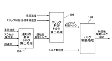
- FIG. 2 is a control block diagram showing a drive torque calculation process of the vehicle control device 17 according to the first embodiment.
- the driver-required torque calculation processing unit 101 calculates the driver-required torque based on the vehicle speed, the accelerator operation amount, and the acceleration of the vehicle.
- the coast torque which is a negative torque simulating the engine braking force
- the creep torque which is a positive torque
- the vehicle speed is calculated from the rotation speed information acquired by the rear motor 7 from the wheel speed sensor 11 and the resolver 13 for the rear wheels, but the vehicle speed may be calculated from other sensors.
- the slip control torque calculation processing unit 103 calculates the drive torque limit value during acceleration or the braking torque limit value during deceleration from the vehicle speed, slip control target wheel speed, and driver-required torque, and the torque after receiving the regenerative cooperative brake is the above.
- the slip control torque limited so as to be within the limit value is calculated.
- the torque limit processing unit 104 limits the slip control torque by various torque limit values such as the battery required torque limit value, and outputs the limited drive torque as a command torque.
- the rear-wheel drive torque after limitation includes both the acceleration side torque and the deceleration side torque of the vehicle.
- FIG. 3 is a control block diagram showing details of the driver-required torque calculation process according to the first embodiment.
- the driver-required torque calculation unit 201 calculates the torque required by the driver based on the accelerator operation amount and the vehicle speed.
- the calculation content is not particularly limited as long as a well-known technical configuration may be appropriately adopted.
- the gradient resistance calculation unit 202 calculates the resistance acting on the vehicle due to the gradient of the road surface based on the vehicle speed and the acceleration which is the value of the acceleration sensor 5. Specifically, the gradient is estimated from the deviation between the estimated acceleration calculated from the vehicle speed and the actual acceleration detected by the acceleration sensor 5. This is to prevent the vehicle deceleration from being excessively reduced when torque is added due to the slope of the downhill.
- the torque calculation unit 203 for the gradient resistance and the required braking force converts the torque corresponding to the required braking force. Specifically, the torque equivalent to the gradient resistance and the creep torque are subtracted from the torque value equivalent to the braking force requirement to avoid applying a torque that generates a driving force exceeding the braking force.
- the control gain calculation unit 204 calculates both the gain according to the vehicle speed and the gain according to the deceleration. Specifically, this is because the peak gain is changed according to the deceleration, and the gain is increased or decreased according to the vehicle speed.
- the added torque calculation unit 205 calculates the added torque capable of suppressing vibration in the pitching direction by multiplying the torque value corresponding to the braking force request by the control gain.
- the addition unit 206 adds the addition torque output from the addition torque calculation unit 205 to the value output from the driver-requested torque calculation unit.
- FIG. 4 is a control block diagram showing details of the gradient resistance calculation unit 202 in the first embodiment.
- the gradient resistance calculation unit 202 includes a stopped information holding unit 2021, an actual gradient estimation unit 2022, a gradient estimation correction unit 2023, and a gradient correction torque map 2024.
- the stop information holding unit 2021 has a stop determination unit a1, an acceleration sensor value storage unit a2, a mileage estimation unit a3, a forgetting gain map a4, a multiplication unit a5, and a deviation calculation unit a6.
- the actual gradient estimation unit 2022 does not have sufficient time for gradient estimation and the performance may deteriorate.
- the actual gradient estimation unit 2022 calculates the deviation between the value output from the acceleration / deceleration speed estimation unit a7 that calculates the estimated acceleration / deceleration speed of the vehicle calculated by differentiating the vehicle speed and the value output from the acceleration sensor 5.
- the actual gradient estimated value which is the current gradient, is estimated based on the acceleration / deceleration rate subtraction unit a8.
- FIG. 5 is a diagram showing the operation of the stop determination unit in the first embodiment.
- the stop determination unit a1 has a function of determining a stop after a specified time after the vehicle speed is equal to or less than the default value and is equal to or less than the default value.
- the reason for waiting for a specified time is that the acceleration sensor value immediately after the vehicle is stopped may be vibrating.
- the acceleration sensor value storage unit a2 has a function of holding the value of the acceleration sensor 5 after the vehicle stop determination unit a1 determines that the vehicle is stopped.
- the mileage estimation unit a3 calculates the mileage from the control cycle time and the vehicle speed.
- FIG. 6 is a forgetting gain map provided in the stopped information holding unit in the first embodiment. This map is a gain for gradually forgetting the stored acceleration sensor value according to the mileage, and is completely forgotten when the default value x1 (m) is reached.
- the multiplication unit a5 the stored acceleration sensor value is multiplied by the oblivion gain according to the mileage to calculate the acceleration sensor value.
- the deviation calculation unit a6 calculates the deviation between the actual gradient estimated value calculated by the actual gradient estimation unit 2022 and the gradient held by the stopped information value holding unit 2021.
- the gradient estimation correction unit 2023 adds the value output from the deviation calculation unit a6 to the actual gradient estimation value and corrects it.
- FIG. 7 is a gradient correction torque map provided in the gradient resistance calculation unit in the first embodiment. If it is an uphill (+), the value corrected to the plus side as the gradient correction torque is output as the gradient correction torque, and if it is the downhill (-), the value corrected to the minus side as the gradient correction torque is the gradient correction torque. I
- FIG. 8 is a control block diagram showing details of the torque calculation unit corresponding to the gradient resistance & braking force requirement in the first embodiment.
- the torque calculation unit 203 corresponding to the gradient resistance & braking force request includes a braking force torque conversion unit 2031, an addition unit 2032, a select unit 2033, and a subtraction unit 2034.
- the braking force torque conversion unit 2031 calculates the torque corresponding to the braking force generated by the braking operation.
- the addition unit 2032 adds the gradient correction torque to the torque corresponding to the braking force.
- the select unit 2033 the torque corresponding to the braking force requirement is limited to 0 so as not to be on the plus side (acceleration side).
- the creep torque amount is subtracted so that the total of the creep torque and the added torque does not exceed the braking force, and the vehicle deceleration does not excessively decrease when the torque is added due to the inertia of the downhill. This prevents the vehicle 1 from accelerating unexpectedly.
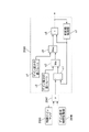
- FIG. 9 is a control block diagram showing details of the control gain calculation unit 204 and the additional torque calculation unit 205 in the first embodiment.
- the control gain calculation unit 204 includes an acceleration estimation value calculation unit 2041, an estimation speed calculation unit 2042, a control gain map (variable acceleration type) 2043, a control gain map (variable speed type) 2048, and a multiplication unit 2045. It has a gain holding time adjusting unit 2046, a multiplying unit 2047, and a control gain rate limit unit 2048. Further, the addition torque calculation unit 205 has a multiplication unit 2051 and a select unit 2052.
- the acceleration estimation value calculation unit 2041 calculates the estimated value of the vehicle acceleration from the differential value of the vehicle speed.
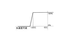
- FIG. 10 is an acceleration variable control gain map
- FIG. 10 is an acceleration variable control gain map
- variable acceleration control gain map 2043 when a deceleration of the specified value x2 (G) or more occurs as an absolute value, the gain is gradually reduced and the deceleration is smaller than the specified value x2 (G) as an absolute value. In this case, the gain is set to 100% to avoid adding torque during sudden braking. Needless to say, at the time of sudden braking, it is desirable to secure the braking force rather than suppressing the vibration in the pitching direction.
- the variable speed control gain map 2044 it is a gain that acts in a suppressive manner according to an increase in the vehicle speed, and is completely set to 0 when the vehicle speed reaches x3 (km / m). It mainly works just before the vehicle stops. By multiplying these two gains, the crossing unit 2045 effectively operates from immediately before the vehicle stops except during sudden deceleration.
- FIG. 12 is a control block diagram showing the details of the gain holding time adjusting unit 2046
- FIG. 13 is a time chart showing the operation of the gain holding time adjusting unit 2046.
- the gain holding time adjusting unit 2046 includes a vehicle stop determination unit b1, a brake ON determination unit b2, a multiplication unit b3, and a predetermined time lapse determination unit b4.
- the stop determination unit b1 determines whether or not the vehicle speed has reached the default value of the stop determination, outputs 1 when it is determined to be stopped, and outputs 0 otherwise.
- the brake ON determination unit b2 outputs 1 when it is determined that the brake is depressed or is in the ON state, and outputs 0 in other cases.
- the multiplication unit b3 outputs 1 when it is determined that the brake is in the ON state and the vehicle has stopped, and outputs 0 in other cases.
- 1 is output from the multiplication unit b3, 1 is output until the preset predetermined time elapses, and 0 is output after the predetermined time elapses, so that the gain is lowered immediately after the vehicle is stopped. Keep the maximum value so that it does not.
- FIG. 14 is a control block diagram showing details of the control gain rate limit unit 2048.
- the control gain rate limit unit 2048 includes a deviation calculation unit c1, a minimum gain output unit c2, a select unit c3, an output unit c4 that outputs the minimum gain decrease rate, a select unit c5, and an addition unit c6. And the previous value holding unit c7.
- the deviation calculation unit c1 calculates the deviation between the gain multiplied by the multiplication unit 2047 and the limited gain.
- the select unit c3 compares the value output from the minimum rate output unit c2 with increased gain with the deviation, and outputs the smaller one. That is, when the gain increases, it is avoided that the gain changes beyond the minimum rate, and the gain is changed smoothly.
- the select unit c5 outputs the larger of the value output from the minimum rate output unit c4 for gain reduction and the value output from the select unit c3. That is, when the gain decreases, it is avoided that the gain changes beyond the minimum rate, and the gain is changed smoothly.
- FIG. 15 is a time chart showing the gain characteristics when the vehicle speed is decreasing.
- the gain output from the control gain map (variable speed type) 2045 is described as 2045 gain, and the value obtained by multiplying the 2045 gain by the value output from the gain holding time adjustment unit 2046 is described as 2047 gain and controlled to 2047 gain.
- the gain on which the gain rate limit portion is applied is referred to as 2048 gain. If the gain is set according to the vehicle speed, such as the 2045 gain, the vehicle can be stopped smoothly, but the gain is continuously generated even after the vehicle is stopped. Therefore, even when the vehicle is stopped, a torque lower than the torque of the friction brake 3 is continuously output from the rear motor 7, resulting in extra power consumption.
- the additional torque calculation unit 205 has a multiplication unit 2051 and a select unit 2052.
- the multiplication unit 2051 outputs a limited control gain by multiplying the torque value corresponding to the braking force request by the gain output from the control gain rate limit unit 2048.
- the select unit 2052 compares the torque value corresponding to the braking force requirement and the limited torque value corresponding to the braking force requirement, and outputs the smaller one as the final added torque.
- FIG. 16 is a time chart showing a change in vehicle speed when the driver-required torque calculation process according to the first embodiment is performed
- FIG. 17 is an experiment in which this control is applied to an actual vehicle and when it is not applied. It is a figure which shows the result.
- the dotted line in the torque column in FIG. 16 represents the torque commensurate with the required braking force
- the alternate long and short dash line represents the torque when there is no control without performing the driver required torque calculation process
- the solid line represents the torque after addition.
- the peak gain is increased or decreased at the timing corresponding to the vehicle stop, the output torque from the rear motor 3 is added without changing the braking force of the friction brake 3, and the friction brake 3 hinders the rotation of the rear wheels 2RR and RL. It was decided to apply the drive side torque within the range below the torque to be applied. As a result, it is possible to suppress the change in acceleration acting on the vehicle while maintaining the braking force of the friction brake 3 (see the “controlled” acceleration column in FIG. 17: inside the square frame). It is conceivable to change the braking torque on the friction brake 3 side, but in this case, there is a limit to the responsiveness of the mechanical inertia from the viewpoint of using the frictional force, and the friction coefficient of the brake pad or the like varies.
- the control device, control method, and control system of the electric vehicle according to the first embodiment have the effects listed below.
- the vehicle control device 17 Obtain the physical quantity related to the speed of vehicle 1 and obtain it.
- the vehicle control device 17 outputs a control command when the physical quantity related to the speed falls below the predetermined speed. Therefore, it is possible to avoid applying unnecessary torque in a normal deceleration state except when the vehicle is stopped.
- the vehicle control device 17 outputs a control command so that the driving force increases as the physical quantity related to the speed decreases and as the physical quantity related to the deceleration of the vehicle 1 decreases. Therefore, the driving force can be effectively generated immediately before the vehicle is stopped except during sudden deceleration.
- the vehicle control device 17 outputs a control command so as to maintain the maximum value of the driving force until a predetermined time elapses after it is determined that the vehicle 1 has stopped. Therefore, it is possible to prevent the torque acting on the drive wheels from suddenly changing after the vehicle is stopped.
- the vehicle control device 17 outputs a control command so that the driving force gradually decreases after maintaining the maximum value of the driving force. Therefore, it is possible to avoid sudden changes in the vehicle posture, torsional resonance of the drive shaft, and the like, and it is possible to suppress vibration and discomfort to the driver.
- the vehicle control device 17 outputs a control command so that the total of the driving force and the force due to the creep phenomenon generated in the vehicle 1 does not exceed the friction braking force. Therefore, it is possible to prevent the vehicle 1 from accelerating unexpectedly.
- the vehicle control device 17 outputs the control command so that the driving force decreases as the road surface gradient in the downward direction when decelerating the vehicle 1 increases. Therefore, it is possible to avoid the generation of torque on the acceleration side due to the influence of the road surface.
- the vehicle control device 17 estimates the road surface gradient based on the difference between the differential value of the physical quantity related to the vehicle speed and the sensor value acquired from the acceleration sensor. Therefore, the road surface gradient can be estimated accurately.
- the vehicle control device 17 includes the difference between the differential value of the physical quantity related to the vehicle speed and the sensor value acquired from the acceleration sensor, and the value acquired and stored from the acceleration sensor when the vehicle 1 is stopped on the road surface gradient. Estimate the road surface gradient based on. That is, when traveling at a low speed on a slope road and stopping again, there is not enough time to estimate the slope and the performance may deteriorate. Therefore, the gradient estimation is performed by using the acceleration sensor value information at the time of the previous stop. The accuracy can be improved.
- a rear motor 7, which is an electric motor, is provided as a drive device. Therefore, the driving force can be controlled by high control accuracy and responsiveness, and the pitching fluctuation when the vehicle is stopped can be effectively suppressed.
- the application is applied to a rear-wheel drive electric vehicle, but a front-wheel drive electric vehicle or a four-wheel drive electric vehicle may be used.
- the vehicle is not limited to an electric vehicle, and may be a vehicle equipped with an engine which is an internal combustion engine or a hybrid vehicle capable of traveling by using both an engine and a motor. That is, when the vehicle is stopped using the friction brake, torque can be applied from the drive source side within a range where the vehicle can be stopped or a braking force acts between the drive wheels and the road surface. Just do it.
- the vehicle control device of this technical idea is in one aspect thereof.
- a vehicle control device provided in a vehicle having a friction braking device that generates a friction braking force in the vehicle and a driving device that generates a driving force in the vehicle.
- the control unit Obtain the physical quantity related to the speed of the vehicle, and Obtain the physical quantity related to the required braking force required to decelerate the vehicle, When the vehicle is decelerated based on the physical quantity related to the required braking force, a control command for generating the driving force by the driving device is output in a state where the friction braking force is generated.
- the control unit When the physical quantity related to the speed falls below the predetermined speed, the control command is output.
- control unit The control command is output so that the driving force increases as the physical quantity related to the speed decreases and as the physical quantity related to the deceleration of the vehicle decreases.
- control unit After it is determined that the vehicle has stopped, the control command is output so as to maintain the maximum value of the driving force until a predetermined time elapses.
- control unit After holding the maximum value of the driving force, the control command is output so that the driving force gradually decreases.
- the control unit The control command is output so that the sum of the driving force and the force generated by the creep phenomenon in the vehicle does not exceed the friction braking force.
- the control unit The control command is output so that the driving force becomes smaller as the road surface gradient in the downward direction when decelerating the vehicle becomes larger.
- the control unit The road surface gradient is estimated based on the difference between the differential value of the physical quantity related to the vehicle speed and the sensor value acquired from the acceleration sensor that detects the acceleration of the vehicle.
- the control unit is based on the difference between the differential value of the physical quantity related to the vehicle speed and the sensor value acquired from the acceleration sensor, and the value acquired and stored from the acceleration sensor when the vehicle is stopped on the road surface gradient. Estimate the road surface gradient.
- the drive device is an electric motor.
- the vehicle control method of the present technical idea is, in one aspect thereof.
- a vehicle control method for controlling a vehicle comprising: a friction braking device that generates a friction braking force in the vehicle and a driving device that generates a driving force in the vehicle.
- the vehicle control system of the present technical idea is in one aspect thereof.
- a friction braking device that generates friction braking force on the vehicle A drive device that generates a driving force in the vehicle, It is a control device that outputs the result of calculation based on the input information.
- the present invention is not limited to the above-described embodiment, and includes various modifications.
- the above-described embodiment has been described in detail in order to explain the present invention in an easy-to-understand manner, and is not necessarily limited to the one including all the described configurations.
- it is possible to replace a part of the configuration of one embodiment with the configuration of another embodiment and it is also possible to add the configuration of another embodiment to the configuration of one embodiment.
Abstract
本発明の一実施形態における車両制御装置、車両制御方法および車両制御システムは、車両の速度に関する物理量と、車両を減速させるために必要な要求制動力に関する物理量をと取得し、要求制動力に関する物理量に基づいて車両を減速させるときに、摩擦制動力が発生している状態で、駆動装置による駆動力を発生させることとした。
Description
本発明は、車両制御装置、車両制御方法および車両制御システムに関する。
特許文献1には、車両が減速状態から車速ゼロに移行する際の車両前後方向加速度を所定許容値以下とするトルク減少開始車速を、回生制動中の回生制動力と、モータ制駆動力の最終目標値と、回生制動力を減少させる所定の減少勾配と、に基づいて設定する車両の前後振動制御装置が開示されている。
しかしながら、特許文献1では、車両速度の低下に合わせて回生制動力を低下させているため、該回生制動力の減少勾配の推定に基づく制御上の誤差によっては、車両停車の際にピッチング変動が生じるおそれがあった。
本発明の目的の一つは、車両停車の際のピッチング変動を抑制することができる車両制御装置、車両制御方法、及び車両制御システムを提供することにある。
本発明の一実施形態における車両制御装置、車両制御方法および車両制御システムは、車両の速度に関する物理量と、車両を減速させるために必要な要求制動力に関する物理量とを取得し、要求制動力に関する物理量に基づいて車両を減速させるときに、摩擦制動力が発生している状態で、駆動装置による駆動力を発生させることとした。
本発明の一実施形態における車両制御装置、車両制御方法および車両制御システムは、車両の速度に関する物理量と、車両を減速させるために必要な要求制動力に関する物理量とを取得し、要求制動力に関する物理量に基づいて車両を減速させるときに、摩擦制動力が発生している状態で、駆動装置による駆動力を発生させることとした。
本発明の一実施形態によれば、車両停車の際のピッチング変動を抑制することができる。
〔実施形態1〕
図1は、実施形態1における電動車両の制御システムの構成図である。
電動車両1は、前輪2FL、2FRと後輪2RL、2RRと、各輪に設けられ車輪に摩擦制動力を発生させる摩擦ブレーキ3FL、3FR、3RL、3RR(以下、各輪の摩擦ブレーキを総称して摩擦ブレーキ3とも記載する。)を有する。
電動車両1は、後輪2RL、2RRにトルクを出力するリアモータ(後輪用電動モータ)7を有する。尚、後輪2RL、2RRを総称して駆動輪2とも記載する。リアモータ7および後輪2RL、2RR間の動力伝達は、減速機8、ディファレンシャル10およびリア車軸6RL、6RRを介して行われる。
各車輪2FL、2FR、2RL、2RRは、車輪速を検出する車輪速センサ11FL、11FR、11RL、11RRを有する。リアモータ7は、モータ回転数を検出する後輪用レゾルバ13を有する。また、電動車両1は、車両の加速度を検出する加速度センサ5を有する。
摩擦ブレーキ3は、各輪と一体に回転するブレーキロータに対し、各輪の回転軸方向にブレーキパッドを押し付けて摩擦力により制動力を発生させる。実施形態1の摩擦ブレーキ3は、ブレーキ液圧により作動するホイルシリンダによってブレーキパッドを押し付ける構成について説明するが、電動モータにより駆動するボールねじ機構等を介してブレーキパッドを押し付ける構成としても良く、特に限定しない。
電動車両1は、低電圧バッテリ14および高電圧バッテリ15を有する。低電圧バッテリ14は、例えば鉛蓄電池である。高電圧バッテリ15は、例えばリチウムイオン電池またはニッケル水素電池である。高電圧バッテリ15は、DC-DCコンバータ16により昇圧された電力により充電される。
電動車両1は、車両制御装置17、ブレーキ制御装置18、リアモータ制御装置20およびバッテリ制御装置19を有する。各制御装置17、18、20は、CANバス21を介してお互いに情報を共有する。
車両制御装置17は、後輪用レゾルバ13、アクセル操作量を検出するアクセルペダルセンサ22、ブレーキ操作量を検出するブレーキセンサ23、ギヤ位置センサ24等の各種センサから情報を取得し、車両の統合制御を行う。車両制御装置17は、ドライバのアクセル操作やブレーキ操作等に応じた要求トルクに対し、要求配分トルクに応じてリアモータ7が出力すべき運転者要求トルクを出力する。
ブレーキ制御装置18は、加速度センサ5と、車輪速センサ11等の各種センサから情報を取得するとともに運転者要求トルクに基づいて、摩擦ブレーキ3に発生させる摩擦ブレーキトルクを算出し、各輪に必要なブレーキ液圧を発生させ、油圧配管18aを通して摩擦ブレーキ3に出力する。
バッテリ制御装置19は、高電圧バッテリ15の充放電状態および高電圧バッテリ15を構成する単電池セルを監視する。バッテリ制御装置19は、高電圧バッテリ15の充放電状態等に基づいて、バッテリ要求トルク制限値を算出する。バッテリ要求トルク制限値は、リアモータ7において許容する最大トルクである。例えば高電圧バッテリ15の充電量が低下しているときには、通常よりもバッテリ要求トルク制限値を小さな値に設定する。
リアモータ制御装置20は、リア要求トルクに基づいてリアモータ7に供給する電力を制御する。
リアモータ制御装置20は、リア要求トルクに基づいてリアモータ7に供給する電力を制御する。
図2は、実施形態1における車両制御装置17の駆動トルク算出処理を表す制御ブロック図である。
運転者要求トルク算出処理部101では、車両速度とアクセル操作量と車両の加速度に基づいて運転者要求トルクを算出する。運転者がアクセルペダルを離しており、かつ車速が所定車速以上の場合はエンジンブレーキ力を模擬した負トルクであるコーストトルクを出力し、車速が低車速領域の場合は正トルクであるクリープトルクを出力する。本処理部における算出の詳細については後述する。尚、車両速度は、車輪速センサ11や後輪用レゾルバ13からのリアモータ7の取得した回転数情報から、推定した車両速度を算定するが、他のセンサから算出してもよい。
スリップ制御トルク算出処理部103では、車両速度とスリップ制御目標車輪速度と運転者要求トルクから加速時における駆動トルク制限値もしくは減速時における制動トルク制限値を算出し、回生協調ブレーキ受け入れ以後トルクが上記制限値の範囲内となるように制限したスリップ制御トルクを算出する。
トルク制限処理部104では、バッテリ要求トルク制限値等の各種トルク制限値によってスリップ制御トルクを制限し、指令トルクとして制限後駆動トルクを出力する。尚、制限後駆動トルクとは、車両の加速側と減速側の両方のトルクを含む。
図3は、実施形態1における運転者要求トルク算出処理の詳細を表す制御ブロック図である。
運転者要求トルク算出部201では、アクセル操作量と車両速度に基づいて運転者が要求しているトルクを算出する。この算出内容については周知の技術構成を適宜採用すればよく特に限定しない。
勾配抵抗算出部202では、車両速度と加速度センサ5の値である加速度とに基づいて、路面の勾配によって車両に作用する抵抗を算出する。具体的には、車両速度から算出される推定加速度と加速度センサ5から検出される実加速度との偏差から勾配推定を行う。下り坂の勾配によりトルク加算時に車両減速度が過度に低下することを回避するためである。
勾配抵抗&制動力要求相当分トルク算出部203では、制動力要求値に相当するトルクに変換する。具体的には制動力要求相当トルク値から勾配抵抗相当分のトルクとクリープトルクを減算し、ブレーキ制動力を上回る駆動力を発生するトルクが印加されることを回避する。
制御ゲイン算出部204では、車両速度に応じたゲインと、減速度に応じたゲインの両方を算出する。具体的には、減速度に応じてピークゲインを変化させ、車両速度によって停車に合わせてゲインを増減させるためである。
加算トルク算出部205では、制動力要求相当分トルク値に対して制御ゲインを乗算してピッチング方向の振動抑制が可能な加算トルクを算出する。
加算部206では、運転者要求トルク算出部から出力された値に加算トルク算出部205から出力された加算トルクを加算する。
図4は、実施形態1における勾配抵抗算出部202の詳細を表す制御ブロック図である。勾配抵抗算出部202は、停車時情報保持部2021と、実勾配推定部2022と、勾配推定補正部2023と、勾配補正トルクマップ2024と、を有する。
停車時情報保持部2021は、停車判定部a1と、加速度センサ値保存部a2と、走行距離推定部a3と、忘却ゲインマップa4と、掛け合わせ部a5と、偏差算出部a6と、を有する。停車時情報保存部2021は、勾配路において低速で走行し、再停車する場合に、実勾配推定部2022では勾配推定に十分な時間がなく、性能が低下するおそれがあることから、前回停車時の加速度センサ値情報を用いて勾配推定精度を向上させることを目的に構成される。
実勾配推定部2022は、車両速度を微分して算出された車両の推定加減速度を算出する加減速度推定部a7から出力された値と、加速度センサ5から出力された値との偏差を算出する加減速度減算部a8と、に基づいて現在の勾配である実勾配推定値を推定する。
図5は、実施形態1における停車判定部の動作を表す図である。停車判定部a1では、車両速度が既定値以下、かつ既定値以下になった後、規定時間後に停車判断をする機能を有する。ここで、規定時間待機するのは、停車直後の加速度センサ値が振動的な場合があるからである。加速度センサ値保存部a2は、停車判定部a1が停車と判定後、加速度センサ5の値を保持する機能を有する。走行距離推定部a3では、制御サイクル時間と車両速度とから走行距離を算出する。
図6は、実施形態1における停車時情報保持部に備えられた忘却ゲインマップである。このマップは、走行距離に応じて保存された加速度センサ値を徐々に忘却させるためのゲインであり、既定値x1(m)に到達したときに完全に忘却させる。掛け合わせ部a5では、保存された加速度センサ値に走行距離に応じた忘却ゲインを乗算し、加速度センサ値を算出する。偏差算出部a6では、実勾配推定部2022で算出された実勾配推定値と、停車時情報値保持部2021で保持された勾配との偏差を演算する。
勾配推定補正部2023では、偏差算出部a6から出力された値を実勾配推定値に加算して補正する。図7は、実施形態1における勾配抵抗算出部に備えられた勾配補正トルクマップである。上り勾配(+)であれば勾配補正トルクとしてプラス側に補正された値が勾配補正トルクとして出力され、下り勾配(―)であれば勾配補正トルクとしてマイナス側に補正された値が勾配補正トルクとして出力される。
勾配推定補正部2023では、偏差算出部a6から出力された値を実勾配推定値に加算して補正する。図7は、実施形態1における勾配抵抗算出部に備えられた勾配補正トルクマップである。上り勾配(+)であれば勾配補正トルクとしてプラス側に補正された値が勾配補正トルクとして出力され、下り勾配(―)であれば勾配補正トルクとしてマイナス側に補正された値が勾配補正トルクとして出力される。
図8は、実施形態1における勾配抵抗&制動力要求相当分トルク算出部の詳細を表す制御ブロック図である。勾配抵抗&制動力要求相当分トルク算出部203は、制動力トルク変換部2031と、加算部2032と、セレクト部2033と、減算部2034と、を有する。制動力トルク変換部2031は、ブレーキ操作により発生する制動力に相当するトルクを算出する。加算部2032は、制動力に相当するトルクに勾配補正トルクを加算する。セレクト部2033では、制動力要求相当分のトルクがプラス側(加速側)とならないように0で制限する。減算部2034では、クリープトルク分を減算し、クリープトルクと加算トルクの合計が制動力を上回らないように、下り坂の慣性でトルク加算時に車両減速度が過度に低下しないようにする。これにより、車両1が意に反して加速することを回避する。
図9は、実施形態1における制御ゲイン算出部204及び加算トルク算出部205の詳細を表す制御ブロック図である。制御ゲイン算出部204は、加速度推定値算出部2041と、推定速度算出部2042と、制御ゲインマップ(加速度可変型)2043と、制御ゲインマップ(速度可変型)2044と、掛け合わせ部2045と、ゲイン保持時間調整部2046と、乗算部2047と、制御ゲインレートリミット部2048と、を有する。また、加算トルク算出部205は、乗算部2051と、セレクト部2052と、を有する。
加速度推定値算出部2041は、車両速度の微分値から車両加速度の推定値を算出する。図10は加速度可変型制御ゲインマップ、図11は速度可変型制御ゲインマップである。加速度可変型制御ゲインマップ2043では、絶対値として規定値x2(G)以上の減速度が生じる場合には、徐々にゲインを小さくし、絶対値として規定値x2(G)よりも小さな減速度の場合には100%にゲイン設定するため、急制動時にトルクが加算されることを回避する。尚、急制動時には、ピッチング方向の振動を抑制することよりも制動力を確保することが望ましいことは言うまでもない。また、速度可変型制御ゲインマップ2044では、車両速度の増加に応じて抑制的に作用するためのゲインであり、車両速度がx3(km/m)に到達すると完全に0が設定されるため、主に停車直前に作用する。掛け合わせ部2045では、これら両ゲインを掛け合わせることで、急減速時以外であって車両停止直前から効果的に作用させる。
加速度推定値算出部2041は、車両速度の微分値から車両加速度の推定値を算出する。図10は加速度可変型制御ゲインマップ、図11は速度可変型制御ゲインマップである。加速度可変型制御ゲインマップ2043では、絶対値として規定値x2(G)以上の減速度が生じる場合には、徐々にゲインを小さくし、絶対値として規定値x2(G)よりも小さな減速度の場合には100%にゲイン設定するため、急制動時にトルクが加算されることを回避する。尚、急制動時には、ピッチング方向の振動を抑制することよりも制動力を確保することが望ましいことは言うまでもない。また、速度可変型制御ゲインマップ2044では、車両速度の増加に応じて抑制的に作用するためのゲインであり、車両速度がx3(km/m)に到達すると完全に0が設定されるため、主に停車直前に作用する。掛け合わせ部2045では、これら両ゲインを掛け合わせることで、急減速時以外であって車両停止直前から効果的に作用させる。
図12は、ゲイン保持時間調整部2046の詳細を表す制御ブロック図、図13は、ゲイン保持時間調整部2046における作用を表すタイムチャートである。ゲイン保持時間調整部2046は、停車判断部b1と、ブレーキON判断部b2と、乗算部b3と、所定時間経過判断部b4と、を有する。停車判断部b1は、車両速度が停車判断の既定値になったか否かを判断し、停車と判断しているときは1を出力し、それ以外は0を出力する。ブレーキON判断部b2は、ブレーキが踏み込またON状態と判断したときには1を出力し、それ以外は0を出力する。乗算部b3は、ブレーキがON状態でかつ停車したと判断された場合に1を出力し、それ以外は0を出力する。所定時間経過判断部b4では、乗算部b3から1が出力され、予め設定された所定時間が経過するまで1を出力し、所定時間経過後に0を出力することで、停車後にすぐにゲインが低下しないよう、最大値を保持させる。
図14は、制御ゲインレートリミット部2048の詳細を表す制御ブロック図である。制御ゲインレートリミット部2048は、偏差演算部c1と、ゲイン増加の最小レート出力部c2と、セレクト部c3と、ゲイン減少の最小レートを出力する出力部c4と、セレクト部c5と、加算部c6と、前回値保持部c7と、を有する。偏差演算部c1では、乗算部2047で乗算されたゲインと、制限されたゲインとの偏差を算出する。セレクト部c3では、ゲイン増加の最小レート出力部c2から出力された値と偏差とを比較し、小さい方を出力する。すなわち、ゲインが増加する際に最小レート以上にゲインが変化することを回避し、なめらかに変化させる。セレクト部c5では、ゲイン減少の最小レート出力部c4から出力された値とセレクト部c3から出力された値のうち大きい方を出力する。すなわち、ゲインが減少する際に最小レート以上にゲインが変化することを回避し、なめらかに変化させる。
図15は、車両速度が低下している際のゲイン特性を表すタイムチャートである。制御ゲインマップ(速度可変型)2045から出力されるゲインを2045ゲインと記載し、2045ゲインにゲイン保持時間調整部2046から出力された値を乗算した値を2047ゲインと記載し、2047ゲインに制御ゲインレートリミット部を作用させたゲインを2048ゲインと記載する。
2045ゲインのように車速に応じたゲインを設定すると、車両をなめらかに停車可能であるものの、車両停止後も継続してゲインが発生してしまう。よって、車両停車中も摩擦ブレーキ3のトルクより低いトルクをリアモータ7から出力し続けてしまい、余分な電力消費が生じる。次に、2047ゲインの場合、なめらかに停車できるとともに、2045ゲインと比較した場合は、余分な電力消費を低減できる。しかしながら、急激なゲイン変動により、車両停止後に車両姿勢の急変や、ドライブシャフトのねじれ共振などが要因となって、振動や運転者への違和感が発生するおそれがある。これに対し、2048ゲインを採用した場合、ゲインの変動を制限することになるため、他のゲインに比べてなめらかにゲインが変動する。これにより、車両姿勢の急変やドライブシャフトのねじれ共振等を回避することができ、振動や運転者への違和感を抑制できる。
2045ゲインのように車速に応じたゲインを設定すると、車両をなめらかに停車可能であるものの、車両停止後も継続してゲインが発生してしまう。よって、車両停車中も摩擦ブレーキ3のトルクより低いトルクをリアモータ7から出力し続けてしまい、余分な電力消費が生じる。次に、2047ゲインの場合、なめらかに停車できるとともに、2045ゲインと比較した場合は、余分な電力消費を低減できる。しかしながら、急激なゲイン変動により、車両停止後に車両姿勢の急変や、ドライブシャフトのねじれ共振などが要因となって、振動や運転者への違和感が発生するおそれがある。これに対し、2048ゲインを採用した場合、ゲインの変動を制限することになるため、他のゲインに比べてなめらかにゲインが変動する。これにより、車両姿勢の急変やドライブシャフトのねじれ共振等を回避することができ、振動や運転者への違和感を抑制できる。
加算トルク算出部205(図9参照)は、乗算部2051とセレクト部2052とを有する。乗算部2051では、制動力要求相当トルク値に制御ゲインレートリミット部2048から出力されたゲインを乗算して制限された制御ゲインを出力する。セレクト部2052では、制動力要求相当トルク値と制限された制動力要求相当トルク値とを比較し、小さい方を最終的な加算トルクとして出力する。
図16は、実施形態1における運転者要求トルク算出処理を実施した場合の車両速度の変化を表すタイムチャート、図17は、実際の車両に本制御を適用した場合と、適用しない場合との実験結果を表す図である。図16中のトルクの欄の点線は要求制動力に釣り合うトルクを表し、一点鎖線は運転者要求トルク算出処理を実施しない制御無しの場合のトルクを表し、実線は加算後トルクを表す。
すなわち、運転者がブレーキペダルを踏み込んだ状態で車両停止に至ると、運転者のブレーキペダルの踏み込み状態に基づいて運転者要求トルクとしての要求制動力が算出される。よって、車両停止に必要な制動力以上の制動力が摩擦ブレーキ3によって付与され続ける。そうすると、停車直前に摩擦ブレーキ3の摩擦係数が動摩擦係数から静止摩擦係数に急激に切り替わることで、車両速度が急激に落ち込みやすく、加速度の急変を招きやすい(図17の「制御無し」の加速度の欄:四角枠内参照)。
そこで、車両停車に合わせたタイミングにおいてピークゲインを増減させ、摩擦ブレーキ3の制動力は変更することなく、リアモータ3からの出力トルクを加算し、摩擦ブレーキ3が後輪2RR,RLの回転を阻害するトルク以下の範囲で、駆動側トルクを付与することとした。これにより、摩擦ブレーキ3の制動力は確保したまま、車両に作用する加速度変化を抑制することができる(図17の「制御あり」の加速度の欄:四角枠内参照)。
尚、摩擦ブレーキ3側の制動トルクを変更することも考えられるが、この場合、摩擦力を使用する観点から機械的なイナーシャの応答性に限界があり、更にブレーキパッド等の摩擦係数のばらつきの影響によって、制御精度を確保することが困難である。これに対し、摩擦ブレーキ3の制動トルクを確保した状態でリアモータ3からの出力トルクを加算することで、摩擦ブレーキ3の摩擦係数変化などによるトルク変動を抑制することができ、車両停止時におけるピッチング振動を効果的に抑制できる。
尚、摩擦ブレーキ3側の制動トルクを変更することも考えられるが、この場合、摩擦力を使用する観点から機械的なイナーシャの応答性に限界があり、更にブレーキパッド等の摩擦係数のばらつきの影響によって、制御精度を確保することが困難である。これに対し、摩擦ブレーキ3の制動トルクを確保した状態でリアモータ3からの出力トルクを加算することで、摩擦ブレーキ3の摩擦係数変化などによるトルク変動を抑制することができ、車両停止時におけるピッチング振動を効果的に抑制できる。
実施形態1の電動車両の制御装置、制御方法および制御システムにあっては、以下に列挙する作用効果を奏する。
(1)車両1に摩擦制動力を発生させる摩擦ブレーキ3(摩擦制動装置)と、車両1に駆動力を発生させるリアモータ7(駆動装置)と、を有する車両1に備えられ、入力した情報に基づいて演算した結果を出力する車両制御装置17(コントロール部)を備える車両制御装置であって、
車両制御装置17は、
車両1の速度に関する物理量を取得し、
車両1を減速させるために必要な要求制動力に関する物理量を取得し、
要求制動力に関する物理量に基づいて車両1を減速させるときに、摩擦制動力が発生している状態で、リアモータ7による駆動力を発生させるための制御指令を出力する。
よって、摩擦制動力による車両加速度の急変を抑制することができ、車両停車の際のピッチング変動を抑制することができる。
(2)車両制御装置17は、速度に関する物理量が所定速度を下回ると、制御指令を出力する。よって、車両停止を除く通常の減速状態で、不要なトルク付与を回避できる。
(3)車両制御装置17は、速度に関する物理量が小さくなるにつれて、かつ車両1の減速度に関する物理量が小さくなるにつれて駆動力が大きくなるように制御指令を出力する。よって、急減速時以外であって車両停止直前に効果的に駆動力を発生させることができる。
(4)車両制御装置17は、車両1が停車したと判断された後、所定時間を経過するまで駆動力の最大値を保持するように制御指令を出力する。よって、停車後に駆動輪に作用するトルクが急変することを防止できる。
(5)車両制御装置17は、駆動力の最大値を保持した後、徐々に駆動力が低下するように制御指令を出力する。よって、車両姿勢の急変やドライブシャフトのねじれ共振等を回避することができ、振動や運転者への違和感を抑制できる。
(6)車両制御装置17は、駆動力と車両1に発生するクリープ現象による力の合計が、摩擦制動力を超えないように制御指令を出力する。よって、車両1が意に反して加速することを回避できる。
(7)車両制御装置17は、車両1を減速させるときの下り方向の路面勾配が大きくなるにつれて、駆動力が小さくなるように前記制御指令を出力する。よって、路面の影響により加速側のトルクが生じることを回避できる。
(7)車両制御装置17は、車両1を減速させるときの下り方向の路面勾配が大きくなるにつれて、駆動力が小さくなるように前記制御指令を出力する。よって、路面の影響により加速側のトルクが生じることを回避できる。
(8)車両制御装置17は、車速に関する物理量の微分値と、加速度センサから取得したセンサ値と、の差に基づいて路面勾配を推定する。よって、路面勾配を精度良く推定できる。
(9)車両制御装置17は、車速に関する物理量の微分値と、加速度センサから取得したセンサ値との差と、車両1が路面勾配で停車したときの加速度センサから取得して記憶した値と、に基づいて路面勾配を推定する。すなわち、勾配路において低速で走行し、再停車する場合に、勾配推定に十分な時間がなく、性能が低下するおそれがあることから、前回停車時の加速度センサ値情報を用いることで、勾配推定精度を向上させることができる。
(10)実施形態1では、駆動装置として電動モータであるリアモータ7を備えた。よって、高い制御精度と応答性によって駆動力を制御することができ、効果的に車両停車の際のピッチング変動を抑制することができる。
〔他の実施形態〕
以上、本発明を実施するための実施形態を説明したが、本発明の具体的な構成は実施形態の構成に限定されるものではなく、発明の要旨を逸脱しない範囲の設計変更等があっても本発明に含まれる。
例えば、本実施形態では、後輪駆動の電動車両に適用したが、前輪駆動の電動車両や四輪駆動の電動車両でもよい。また、電動車両に限らず、内燃機関であるエンジンを備えた車両や、エンジンとモータの両方を用いて走行可能なハイブリッド車両であってもよい。すなわち、摩擦ブレーキを用いた車両停止時に、車両が停止可能な範囲で、もしくは駆動輪と路面との間に制動力が働く範囲で、駆動源側からトルクを付与することが可能な構成であればよい。
以上、本発明を実施するための実施形態を説明したが、本発明の具体的な構成は実施形態の構成に限定されるものではなく、発明の要旨を逸脱しない範囲の設計変更等があっても本発明に含まれる。
例えば、本実施形態では、後輪駆動の電動車両に適用したが、前輪駆動の電動車両や四輪駆動の電動車両でもよい。また、電動車両に限らず、内燃機関であるエンジンを備えた車両や、エンジンとモータの両方を用いて走行可能なハイブリッド車両であってもよい。すなわち、摩擦ブレーキを用いた車両停止時に、車両が停止可能な範囲で、もしくは駆動輪と路面との間に制動力が働く範囲で、駆動源側からトルクを付与することが可能な構成であればよい。
[実施例から把握しうる技術的思想]
以上説明した実施例から把握しうる技術的思想(又は技術的解決策。以下同じ。)について、以下に記載する。
(1) 本技術的思想の車両制御装置は、その1つの態様において、
車両に摩擦制動力を発生させる摩擦制動装置と、前記車両に駆動力を発生させる駆動装置と、を有する前記車両に設けられる車両制御装置であって、
入力された情報に基づいて演算した結果を出力するコントロール部を備え、
前記コントロール部は、
前記車両の速度に関する物理量を取得し、
前記車両を減速させるために必要な要求制動力に関する物理量を取得し、
前記要求制動力に関する物理量に基づいて前記車両を減速させるときに、前記摩擦制動力が発生している状態で、前記駆動装置による駆動力を発生させるための制御指令を出力する。
(2) より好ましい態様では、前記態様において、
前記コントロール部は、
前記速度に関する物理量が所定速度を下回ると、前記制御指令を出力する。
(3) 別の好ましい態様では、前記態様のいずれかにおいて、
前記コントロール部は、
前記速度に関する物理量が小さくなるにつれて、かつ前記車両の減速度に関する物理量が小さくなるにつれて、前記駆動力が大きくなるように前記制御指令を出力する。
(4) さらに別の好ましい態様では、前記態様のいずれかにおいて、
前記コントロール部は、
前記車両が停車したと判断された後、所定時間を経過するまで前記駆動力の最大値を保持するように前記制御指令を出力する。
(5) さらに別の好ましい態様では、前記態様のいずれかにおいて、
前記コントロール部は、
前記駆動力の最大値を保持した後、前記駆動力が徐々に低下するように前記制御指令を出力する。
(6) さらに別の好ましい態様では、前記態様のいずれかにおいて、
前記コントロール部は、
前記駆動力と前記車両に発生するクリープ現象による力との合計が、前記摩擦制動力を超えないように前記制御指令を出力する。
(7) さらに別の好ましい態様では、前記態様のいずれかにおいて、
前記コントロール部は、
前記車両を減速させるときの下り方向の路面勾配が大きくなるにつれて、前記駆動力が小さくなるように前記制御指令を出力する。
(8) さらに別の好ましい態様では、前記態様のいずれかにおいて、
前記コントロール部は、
前記車速に関する物理量の微分値と、車両の加速度を検出する加速度センサから取得したセンサ値と、の差に基づいて前記路面勾配を推定する。
(9) さらに別の好ましい態様では、前記態様のいずれかにおいて、
前記コントロール部は、
前記車速に関する物理量の微分値と、加速度センサから取得したセンサ値と、の差と、前記車両が前記路面勾配で停車したときの前記加速度センサから取得して記憶された値と、に基づいて前記路面勾配を推定する。
(10) さらに別の好ましい態様では、前記態様のいずれかにおいて、
前記駆動装置は、電動モータである。
(11) また、他の観点から、本技術的思想の車両制御方法は、その1つの態様において、
車両に摩擦制動力を発生させる摩擦制動装置と、前記車両に駆動力を発生させる駆動装置と、を備える前記車両を制御する車両制御方法であって、
前記車両の速度に関する物理量を取得し、
前記車両を減速させるために必要な要求制動力に関する物理量を取得し、
前記要求制動力に関する物理量に基づいて前記車両を減速させるときに、前記摩擦制動力が発生している状態で、前記駆動装置による駆動力を発生させるための制御指令を出力する。
(12) また、他の観点から、本技術的思想の車両制御システムは、その1つの態様において、
車両に摩擦制動力を発生させる摩擦制動装置と、
前記車両に駆動力を発生させる駆動装置と、
入力された情報に基づいて演算した結果を出力する制御装置であって、
前記車両の速度に関する物理量を取得し、
前記車両を減速させるために必要な要求制動力に関する物理量を取得し、
前記要求制動力に関する物理量に基づいて前記車両を減速させるときに、前記摩擦制動力が発生している状態で、前記駆動装置による駆動力を発生させるための制御指令を出力する、
制御装置と、
を備える。
なお、本発明は上記した実施形態に限定されるものではなく、様々な変形例が含まれる。例えば、上記した実施形態は本発明を分かりやすく説明するために詳細に説明したものであり、必ずしも説明した全ての構成を備えるものに限定されるものではない。また、ある実施形態の構成の一部を他の実施形態の構成に置き換えることが可能であり、また、ある実施形態の構成に他の実施形態の構成を加えることも可能である。また、各実施形態の構成の一部について、他の構成の追加・削除・置換をすることが可能である。
本願は、2020年9月30日付出願の日本国特許出願第2020-164411号に基づく優先権を主張する。2020年9月30日付出願の日本国特許出願第2020-164411号の明細書、特許請求の範囲、図面、および要約書を含む全開示内容は、参照により本願に全体として組み込まれる。
1 電動車両
2RL、2RR 後輪
3 摩擦ブレーキ
5 加速度センサ
7 リアモータ
11 車輪速センサ
13 後輪用レゾルバ
17 車両制御装置
18 ブレーキ制御装置
20 リアモータ制御装置
22 アクセルペダルセンサ
23 ブレーキセンサ
2RL、2RR 後輪
3 摩擦ブレーキ
5 加速度センサ
7 リアモータ
11 車輪速センサ
13 後輪用レゾルバ
17 車両制御装置
18 ブレーキ制御装置
20 リアモータ制御装置
22 アクセルペダルセンサ
23 ブレーキセンサ
Claims (14)
- 車両に摩擦制動力を発生させる摩擦制動装置と、前記車両に駆動力を発生させる駆動装置と、を有する前記車両に設けられる車両制御装置であって、
入力された情報に基づいて演算した結果を出力するコントロール部を備え、
前記コントロール部は、
前記車両の速度に関する物理量を取得し、
前記車両を減速させるために必要な要求制動力に関する物理量を取得し、
前記要求制動力に関する物理量に基づいて前記車両を減速させるときに、前記摩擦制動力が発生している状態で、前記駆動装置による駆動力を発生させるための制御指令を出力する、
車両制御装置。 - 請求項1に記載の車両制御装置であって、
前記コントロール部は、
前記速度に関する物理量が所定速度を下回ると、前記制御指令を出力する、
車両制御装置。 - 請求項2に記載の車両制御装置であって、
前記コントロール部は、
前記速度に関する物理量が小さくなるにつれて、かつ前記車両の減速度に関する物理量が小さくなるにつれて、前記駆動力が大きくなるように前記制御指令を出力する、
車両制御装置。 - 請求項3に記載の車両制御装置であって、
前記コントロール部は、
前記車両が停車したと判断された後、所定時間を経過するまで前記駆動力の最大値を保持するように前記制御指令を出力する、
車両制御装置。 - 請求項4に記載の車両制御装置であって、
前記コントロール部は、
前記駆動力の最大値を保持した後、前記駆動力が徐々に低下するように前記制御指令を出力する、
車両制御装置。 - 請求項2に記載の車両制御装置であって、
前記コントロール部は、
前記車両が停車したと判断された後、所定時間を経過するまで前記駆動力の最大値を保持するように前記制御指令を出力する、
車両制御装置。 - 請求項2に記載の車両制御装置であって、
前記コントロール部は、
前記駆動力の最大値を保持した後、前記駆動力が徐々に低下するように前記制御指令を出力する、
車両制御装置。 - 請求項2に記載の車両制御装置であって、
前記コントロール部は、
前記駆動力と前記車両に発生するクリープ現象による力との合計が、前記摩擦制動力を超えないように前記制御指令を出力する、
車両制御装置。 - 請求項8に記載の車両制御装置であって、
前記コントロール部は、
前記車両を減速させるときの下り方向の路面勾配が大きくなるにつれて、前記駆動力が小さくなるように前記制御指令を出力する、
車両制御装置。 - 請求項9に記載の車両制御装置であって、
前記コントロール部は、
前記車速に関する物理量の微分値と、前記車両の加速度を検出する加速度センサから取得したセンサ値と、の差に基づいて前記路面勾配を推定する、
車両制御装置。 - 請求項10に記載の車両制御装置であって、
前記コントロール部は、
前記車速に関する物理量の微分値と、前記加速度センサから取得したセンサ値と、の差と、前記車両が前記路面勾配で停車したときの前記加速度センサから取得して記憶された値と、に基づいて前記路面勾配を推定する、
車両制御装置。 - 請求項1に記載の車両制御装置であって、
前記駆動装置は、電動モータである、
車両制御装置。 - 車両に摩擦制動力を発生させる摩擦制動装置と、前記車両に駆動力を発生させる駆動装置と、を備える前記車両を制御する車両制御方法であって、
前記車両の速度に関する物理量を取得し、
前記車両を減速させるために必要な要求制動力に関する物理量を取得し、
前記要求制動力に関する物理量に基づいて前記車両を減速させるときに、前記摩擦制動力が発生している状態で、前記駆動装置による駆動力を発生させるための制御指令を出力する、
車両制御方法。 - 車両制御システムであって、
車両に摩擦制動力を発生させる摩擦制動装置と、
前記車両に駆動力を発生させる駆動装置と、
入力された情報に基づいて演算した結果を出力する制御装置であって、
前記車両の速度に関する物理量を取得し、
前記車両を減速させるために必要な要求制動力に関する物理量を取得し、
前記要求制動力に関する物理量に基づいて前記車両を減速させるときに、前記摩擦制動力が発生している状態で、前記駆動装置による駆動力を発生させるための制御指令を出力する、
制御装置と、
を備える車両制御システム。
Priority Applications (3)
| Application Number | Priority Date | Filing Date | Title |
|---|---|---|---|
| US18/024,608 US20230322195A1 (en) | 2020-09-30 | 2021-08-19 | Vehicle control device, vehicle control method, and vehicle control system |
| EP21874961.2A EP4223607A1 (en) | 2020-09-30 | 2021-08-19 | Vehicle control device, vehicle control method, and vehicle control system |
| CN202180063360.4A CN116194349A (zh) | 2020-09-30 | 2021-08-19 | 车辆控制装置、车辆控制方法以及车辆控制系统 |
Applications Claiming Priority (2)
| Application Number | Priority Date | Filing Date | Title |
|---|---|---|---|
| JP2020164411A JP2022056583A (ja) | 2020-09-30 | 2020-09-30 | 車両制御装置、車両制御方法および車両制御システム |
| JP2020-164411 | 2020-09-30 |
Publications (1)
| Publication Number | Publication Date |
|---|---|
| WO2022070658A1 true WO2022070658A1 (ja) | 2022-04-07 |
Family
ID=80949906
Family Applications (1)
| Application Number | Title | Priority Date | Filing Date |
|---|---|---|---|
| PCT/JP2021/030350 WO2022070658A1 (ja) | 2020-09-30 | 2021-08-19 | 車両制御装置、車両制御方法および車両制御システム |
Country Status (5)
| Country | Link |
|---|---|
| US (1) | US20230322195A1 (ja) |
| EP (1) | EP4223607A1 (ja) |
| JP (1) | JP2022056583A (ja) |
| CN (1) | CN116194349A (ja) |
| WO (1) | WO2022070658A1 (ja) |
Cited By (2)
| Publication number | Priority date | Publication date | Assignee | Title |
|---|---|---|---|---|
| WO2024048321A1 (ja) * | 2022-09-01 | 2024-03-07 | 日立Astemo株式会社 | 車両制御装置、車両制御方法および車両制御システム |
| WO2024048322A1 (ja) * | 2022-09-01 | 2024-03-07 | 日立Astemo株式会社 | 車両制御装置、車両制御方法および車両制御システム |
Families Citing this family (1)
| Publication number | Priority date | Publication date | Assignee | Title |
|---|---|---|---|---|
| JP2024034575A (ja) * | 2022-09-01 | 2024-03-13 | 日立Astemo株式会社 | 車両制御装置、車両制御方法および車両制御システム |
Citations (6)
| Publication number | Priority date | Publication date | Assignee | Title |
|---|---|---|---|---|
| JPS6212305A (ja) * | 1985-07-06 | 1987-01-21 | Toyota Motor Corp | 電気自動車のピツチング抑制装置 |
| JP2006284414A (ja) * | 2005-04-01 | 2006-10-19 | Xanavi Informatics Corp | 車載情報端末、自動車の走行制御システム、自動車の走行制御装置及び方法 |
| JP2007030631A (ja) * | 2005-07-25 | 2007-02-08 | Advics:Kk | 車両用ブレーキ制御装置 |
| JP2011259645A (ja) * | 2010-06-11 | 2011-12-22 | Hitachi Constr Mach Co Ltd | 電動車両のピッチング制御装置 |
| JP2013179728A (ja) * | 2012-02-28 | 2013-09-09 | Nissan Motor Co Ltd | 車体制振制御装置 |
| JP2020164411A (ja) | 2019-03-28 | 2020-10-08 | 三菱マテリアル株式会社 | セメント組成物及びその製造方法 |
-
2020
- 2020-09-30 JP JP2020164411A patent/JP2022056583A/ja active Pending
-
2021
- 2021-08-19 WO PCT/JP2021/030350 patent/WO2022070658A1/ja unknown
- 2021-08-19 EP EP21874961.2A patent/EP4223607A1/en active Pending
- 2021-08-19 CN CN202180063360.4A patent/CN116194349A/zh active Pending
- 2021-08-19 US US18/024,608 patent/US20230322195A1/en active Pending
Patent Citations (6)
| Publication number | Priority date | Publication date | Assignee | Title |
|---|---|---|---|---|
| JPS6212305A (ja) * | 1985-07-06 | 1987-01-21 | Toyota Motor Corp | 電気自動車のピツチング抑制装置 |
| JP2006284414A (ja) * | 2005-04-01 | 2006-10-19 | Xanavi Informatics Corp | 車載情報端末、自動車の走行制御システム、自動車の走行制御装置及び方法 |
| JP2007030631A (ja) * | 2005-07-25 | 2007-02-08 | Advics:Kk | 車両用ブレーキ制御装置 |
| JP2011259645A (ja) * | 2010-06-11 | 2011-12-22 | Hitachi Constr Mach Co Ltd | 電動車両のピッチング制御装置 |
| JP2013179728A (ja) * | 2012-02-28 | 2013-09-09 | Nissan Motor Co Ltd | 車体制振制御装置 |
| JP2020164411A (ja) | 2019-03-28 | 2020-10-08 | 三菱マテリアル株式会社 | セメント組成物及びその製造方法 |
Cited By (2)
| Publication number | Priority date | Publication date | Assignee | Title |
|---|---|---|---|---|
| WO2024048321A1 (ja) * | 2022-09-01 | 2024-03-07 | 日立Astemo株式会社 | 車両制御装置、車両制御方法および車両制御システム |
| WO2024048322A1 (ja) * | 2022-09-01 | 2024-03-07 | 日立Astemo株式会社 | 車両制御装置、車両制御方法および車両制御システム |
Also Published As
| Publication number | Publication date |
|---|---|
| US20230322195A1 (en) | 2023-10-12 |
| JP2022056583A (ja) | 2022-04-11 |
| EP4223607A1 (en) | 2023-08-09 |
| CN116194349A (zh) | 2023-05-30 |
Similar Documents
| Publication | Publication Date | Title |
|---|---|---|
| WO2022070658A1 (ja) | 車両制御装置、車両制御方法および車両制御システム | |
| CN111601731B (zh) | 电动车辆的控制装置、控制系统以及控制方法 | |
| US8342618B2 (en) | Traction control device for vehicle | |
| US11584225B2 (en) | One-pedal speed control for off-road driving | |
| JP5596756B2 (ja) | 電動車両 | |
| CN114248770A (zh) | 单踏板驾驶模式下的上坡车辆起步 | |
| JP2007131093A (ja) | 車両用減速制御装置 | |
| US20150274033A1 (en) | Wheel control device, vehicle, and wheel control method | |
| JP2006264628A (ja) | 車輌の制駆動力制御装置 | |
| CN110799397B (zh) | 车辆控制装置、车辆控制系统和车辆控制方法 | |
| JP2023174056A (ja) | 制駆動力制御装置 | |
| JP4239861B2 (ja) | 車両の挙動制御装置 | |
| US11472384B2 (en) | Drive control apparatus for drive system of vehicle | |
| WO2024048322A1 (ja) | 車両制御装置、車両制御方法および車両制御システム | |
| JP2005219580A (ja) | 車両の挙動制御装置 | |
| CN113879306A (zh) | 车辆驱动系统 | |
| WO2024048323A1 (ja) | 車両制御装置、車両制御方法および車両制御システム | |
| WO2023281975A1 (ja) | 車両制御装置、車両制御方法および車両制御システム | |
| WO2024048321A1 (ja) | 車両制御装置、車両制御方法および車両制御システム | |
| JP2006238528A (ja) | バッテリ蓄電余裕を考慮した回生制動を伴う車輌用制動装置 | |
| JP2023021494A (ja) | 車両制御装置、車両制御方法および車両制御システム | |
| WO2022138092A1 (ja) | 制御装置 | |
| WO2021145301A1 (ja) | 電動車両の制御装置、電動車両の制御方法および電動車両の制御システム | |
| JP2024058480A (ja) | 車両の回生協調制動制御装置 | |
| JP2019103320A (ja) | 車両用制御装置及び車両の制御方法 |
Legal Events
| Date | Code | Title | Description |
|---|---|---|---|
| 121 | Ep: the epo has been informed by wipo that ep was designated in this application |
Ref document number: 21874961 Country of ref document: EP Kind code of ref document: A1 |
|
| NENP | Non-entry into the national phase |
Ref country code: DE |
|
| ENP | Entry into the national phase |
Ref document number: 2021874961 Country of ref document: EP Effective date: 20230502 |