WO2022070538A1 - ブラシレスモータ - Google Patents
ブラシレスモータ Download PDFInfo
- Publication number
- WO2022070538A1 WO2022070538A1 PCT/JP2021/024719 JP2021024719W WO2022070538A1 WO 2022070538 A1 WO2022070538 A1 WO 2022070538A1 JP 2021024719 W JP2021024719 W JP 2021024719W WO 2022070538 A1 WO2022070538 A1 WO 2022070538A1
- Authority
- WO
- WIPO (PCT)
- Prior art keywords
- rotor
- shaft
- brushless motor
- yoke
- stator
- Prior art date
- Legal status (The legal status is an assumption and is not a legal conclusion. Google has not performed a legal analysis and makes no representation as to the accuracy of the status listed.)
- Ceased
Links
Images






Classifications
-
- H—ELECTRICITY
- H02—GENERATION; CONVERSION OR DISTRIBUTION OF ELECTRIC POWER
- H02K—DYNAMO-ELECTRIC MACHINES
- H02K29/00—Motors or generators having non-mechanical commutating devices, e.g. discharge tubes or semiconductor devices
-
- H—ELECTRICITY
- H02—GENERATION; CONVERSION OR DISTRIBUTION OF ELECTRIC POWER
- H02K—DYNAMO-ELECTRIC MACHINES
- H02K21/00—Synchronous motors having permanent magnets; Synchronous generators having permanent magnets
- H02K21/12—Synchronous motors having permanent magnets; Synchronous generators having permanent magnets with stationary armatures and rotating magnets
- H02K21/14—Synchronous motors having permanent magnets; Synchronous generators having permanent magnets with stationary armatures and rotating magnets with magnets rotating within the armatures
-
- F—MECHANICAL ENGINEERING; LIGHTING; HEATING; WEAPONS; BLASTING
- F16—ENGINEERING ELEMENTS AND UNITS; GENERAL MEASURES FOR PRODUCING AND MAINTAINING EFFECTIVE FUNCTIONING OF MACHINES OR INSTALLATIONS; THERMAL INSULATION IN GENERAL
- F16C—SHAFTS; FLEXIBLE SHAFTS; ELEMENTS OR CRANKSHAFT MECHANISMS; ROTARY BODIES OTHER THAN GEARING ELEMENTS; BEARINGS
- F16C17/00—Sliding-contact bearings for exclusively rotary movement
- F16C17/04—Sliding-contact bearings for exclusively rotary movement for axial load only
- F16C17/08—Sliding-contact bearings for exclusively rotary movement for axial load only for supporting the end face of a shaft or other member, e.g. footstep bearings
-
- F—MECHANICAL ENGINEERING; LIGHTING; HEATING; WEAPONS; BLASTING
- F16—ENGINEERING ELEMENTS AND UNITS; GENERAL MEASURES FOR PRODUCING AND MAINTAINING EFFECTIVE FUNCTIONING OF MACHINES OR INSTALLATIONS; THERMAL INSULATION IN GENERAL
- F16C—SHAFTS; FLEXIBLE SHAFTS; ELEMENTS OR CRANKSHAFT MECHANISMS; ROTARY BODIES OTHER THAN GEARING ELEMENTS; BEARINGS
- F16C17/00—Sliding-contact bearings for exclusively rotary movement
- F16C17/12—Sliding-contact bearings for exclusively rotary movement characterised by features not related to the direction of the load
- F16C17/24—Sliding-contact bearings for exclusively rotary movement characterised by features not related to the direction of the load with devices affected by abnormal or undesired positions, e.g. for preventing overheating, for safety
- F16C17/246—Sliding-contact bearings for exclusively rotary movement characterised by features not related to the direction of the load with devices affected by abnormal or undesired positions, e.g. for preventing overheating, for safety related to wear, e.g. sensors for measuring wear
-
- H—ELECTRICITY
- H02—GENERATION; CONVERSION OR DISTRIBUTION OF ELECTRIC POWER
- H02K—DYNAMO-ELECTRIC MACHINES
- H02K1/00—Details of the magnetic circuit
- H02K1/06—Details of the magnetic circuit characterised by the shape, form or construction
- H02K1/22—Rotating parts of the magnetic circuit
- H02K1/27—Rotor cores with permanent magnets
- H02K1/2706—Inner rotors
-
- H—ELECTRICITY
- H02—GENERATION; CONVERSION OR DISTRIBUTION OF ELECTRIC POWER
- H02K—DYNAMO-ELECTRIC MACHINES
- H02K15/00—Processes or apparatus specially adapted for manufacturing, assembling, maintaining or repairing of dynamo-electric machines
- H02K15/02—Processes or apparatus specially adapted for manufacturing, assembling, maintaining or repairing of dynamo-electric machines of stator or rotor bodies
- H02K15/03—Processes or apparatus specially adapted for manufacturing, assembling, maintaining or repairing of dynamo-electric machines of stator or rotor bodies having permanent magnets
-
- H—ELECTRICITY
- H02—GENERATION; CONVERSION OR DISTRIBUTION OF ELECTRIC POWER
- H02K—DYNAMO-ELECTRIC MACHINES
- H02K5/00—Casings; Enclosures; Supports
- H02K5/04—Casings or enclosures characterised by the shape, form or construction thereof
- H02K5/16—Means for supporting bearings, e.g. insulating supports or means for fitting bearings in the bearing-shields
- H02K5/167—Means for supporting bearings, e.g. insulating supports or means for fitting bearings in the bearing-shields using sliding-contact or spherical cap bearings
- H02K5/1675—Means for supporting bearings, e.g. insulating supports or means for fitting bearings in the bearing-shields using sliding-contact or spherical cap bearings radially supporting the rotary shaft at only one end of the rotor
-
- H—ELECTRICITY
- H02—GENERATION; CONVERSION OR DISTRIBUTION OF ELECTRIC POWER
- H02K—DYNAMO-ELECTRIC MACHINES
- H02K7/00—Arrangements for handling mechanical energy structurally associated with dynamo-electric machines, e.g. structural association with mechanical driving motors or auxiliary dynamo-electric machines
- H02K7/08—Structural association with bearings
- H02K7/09—Structural association with bearings with magnetic bearings
-
- H—ELECTRICITY
- H02—GENERATION; CONVERSION OR DISTRIBUTION OF ELECTRIC POWER
- H02K—DYNAMO-ELECTRIC MACHINES
- H02K2213/00—Specific aspects, not otherwise provided for and not covered by codes H02K2201/00 - H02K2211/00
- H02K2213/03—Machines characterised by numerical values, ranges, mathematical expressions or similar information
Definitions
- the present invention relates to a brushless motor having a single-axis structure.
- Patent Document 1 describes a brushless motor having a single-axis structure.
- the brushless motor described in Patent Document 1 includes a rotor, a stator, and a preload adjusting mechanism.
- the preload adjustment mechanism is equipped with a mechanism that slides in a helicoid manner. When the sliding ball wears due to use, the preload adjustment mechanism is adjusted and the position of the shaft is corrected by screwing the bottom plate that supports the shaft.
- an object of the present invention is to provide a brushless motor that can more reliably suppress the thrust movement of the rotor even if the thrust generation force is large.
- the brushless motor of the present invention includes a rotor, a stator, a bearing member, a suction generating member, and a suction force assisting member.
- the rotor includes a shaft, a rotor yoke that holds the shaft and covers the peripheral surface of the shaft, and permanent magnets arranged on the outer periphery of the rotor yoke.
- the stator is arranged on the outer peripheral side of the rotor.
- the bearing member rotatably holds the shaft.
- the suction force generating member is arranged at the end of the bearing member on the side where the rotor yoke holds the shaft, and generates a suction force with respect to the rotor yoke.
- the suction force assisting member assists the suction force.
- the thrust movement of the rotor can be suppressed more reliably.
- FIG. 1 is an external perspective view of the brushless motor 10 according to the embodiment of the present invention.
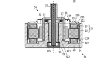
- FIG. 2 is a side sectional view showing the configuration of the brushless motor 10 according to the embodiment of the present invention.
- FIG. 3 is a side sectional view showing the configuration of the stator assembly 20 according to the embodiment of the present invention.
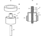
- FIG. 4A is an exploded perspective view of the rotor 30, and
- FIG. 4B is a side sectional view showing the configuration of the rotor 30.
- 5 (A) and 5 (B) are enlarged views of the proximity portion between the rotor 30 and the stator 40.
- FIG. 6 is a graph showing the relationship between the separation distance between the rotor 30 and the stator 40 and the magnetic attraction force.
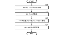
- FIG. 7 is a flowchart showing an example of a method for manufacturing a brushless motor 10 according to an embodiment of the present invention.
- FIG. 8 is a side sectional view showing a configuration example of the pump 1, which is an example of using the brushless motor 10 of the present invention.
- FIG. 9 is a graph showing changes in the required suction force between the rotor 30 and the stator 40 with respect to the rotation speed of the impeller 90.
- FIG. 1 is an external perspective view of the brushless motor 10 according to the embodiment of the present invention.
- FIG. 2 is a side sectional view showing the configuration of the brushless motor 10 according to the embodiment of the present invention.
- FIG. 3 is a side sectional view showing the configuration of the stator assembly 20 according to the embodiment of the present invention.
- FIG. 4A is an exploded perspective view of the rotor 30, and
- FIG. 4B is a side sectional view showing the configuration of the rotor 30.
- the brushless motor 10 includes a stator assembly 20 and a rotor 30.
- the specific structure of the stator assembly 20 and the rotor 30 will be described later.
- the stator assembly 20 has an opening 234.
- the rotor 30 is inserted into the stator assembly 20 through the opening 234.
- the opening 234 overlaps with the central space of the stator 40.
- the rotor 30 is arranged inside the stator 40.
- the stator 40 is arranged on the outer peripheral side of the rotor 30.
- One end of the rotor 30 in the extending direction of the shaft 33 projects outward from the opening 234 side of the stator assembly 20.
- the other end of the rotor 30 in the extending direction of the shaft 33 is rotatably supported by the stator assembly 20.
- the rotation of the rotor 30 is controlled by controlling the signal given to the stator 40.
- the brushless motor 10 realizes an inner rotor type brushless motor having a uniaxial structure.
- stator assembly 20 includes a housing 21, an insulating resin 24, a shaft lid member 25, a bearing 26, a suction magnet 27, a yoke 28, and a stator 40.
- the housing 21 includes a first housing member 22 and a second housing member 23.
- the first housing member 22 and the second housing member 23 are made of a highly rigid material such as SUS.
- the first housing member 22 includes a main wall 221, a side wall 222, and an internal wall 223.
- the main wall 221 is circular in a plan view.
- the side wall 222 has a cylindrical shape, is formed along the outer peripheral end of the main wall 221 and extends in a direction orthogonal to the main surface of the main wall 221.
- the inner wall 223 has a cylindrical shape, is formed in the center of the main wall 221 and extends in a direction orthogonal to the main surface of the main wall 221.
- the inner wall 223 has a hollow portion 225 that opens on both sides of the cylinder.
- the main wall 231 has an opening in a region overlapping the hollow portion 225. Therefore, the hollow portion 225 also communicates with the outside of the first housing member 22 on the main wall 231 side.
- the first housing member 22 has a space 224 surrounded by the main wall 221, the side wall 222, and the inner wall 223.
- the space 224 is annular in a plan view and opens on the side opposite to the main wall 221 side.
- the second housing member 23 includes a main wall 231 and a side wall 232.
- the main wall 231 is circular in a plan view.
- the side wall 232 has a cylindrical shape in a plan view.
- the side wall 232 has a cylindrical shape, is formed along the outer peripheral end of the main wall 231 and extends in a direction orthogonal to the main surface of the main wall 231.
- the second housing member 23 has a space 235 surrounded by the main wall 231 and the side wall 232.
- the space 235 is circular in a plan view and opens on the side opposite to the main wall 231 side.
- the main wall 231 has an opening 234 in the center that penetrates the main wall 231 in the thickness direction.
- the opening 234 communicates with the space 235.
- the opening 234 is circular in plan view.
- the outer shape of the opening 234 is similar to the outer shape of the rotor 30 in a plan view (the outer shape seen from one end or the other end side of the shaft 33).
- the area of the opening 234 is an area into which the rotor 30 can be inserted, and is, for example, about the plane area of the central space of the stator 40.
- the main wall 231 has a plurality of holes 236.
- the plurality of holes 236 penetrate the main wall 231 in the thickness direction and communicate with the space 235.
- the plurality of holes 236 are arranged along the outer circumference of the opening 234.
- the first housing member 22 and the second housing member 23 are assembled to each other. More specifically, in the first housing member 22, the opening of the space 235 is the opening of the space 235 in the second housing member 23 so that the opening of the space 224 faces the second housing member 23 side. Arranged so that it faces to the side. Then, the second housing member 23 is fitted into the first housing member 22 so that the outer wall of the side wall 232 abuts on the inner wall surface 2221 of the side wall 222 of the first housing member 22.
- the housing 21 has an internal space.
- the internal space of the housing 21 communicates with the outside of the second housing member 23 side by the above-mentioned opening 234 and the plurality of holes 236.
- the shaft lid member 25 is disk-shaped and has a recess 250 recessed from the main surface.
- the shaft lid member 25 is arranged near the end of the hollow portion 225 on the main wall 221 side.
- the shaft lid member 25 has a groove for screwing on the outer periphery.
- a groove for screwing is formed on the wall surface of the recess 250 near the end on the main wall 221 side.
- the shaft lid member 25 is screwed into the wall surface forming the recess 250 by these screwing grooves. Then, by adjusting this screwing state, the position of the shaft lid member 25 in the axial direction of the recess 250 (the depth at which the shaft lid member 25 is embedded in the housing 21 (embedding in FIG. 5A).
- the depth HS1 and the embedding depth HS2 in FIG. 5 (B)) are adjusted.
- the bearing 26 has a cylindrical shape, is arranged in the hollow portion 225, and is fixed to the wall on the hollow portion 225 side of the inner wall 223.
- the structure including the bearing 26 and the inner wall 223 corresponds to the "bearing member" of the present invention.
- the suction magnet 27 has an annular shape.
- the attraction magnet 27 is arranged at the tip of the inner wall 223, in other words, at the end of the inner wall 223 opposite to the connection end to the main wall 221.
- the attraction magnet 27 corresponds to the "attraction force generating member" of the present invention.
- the yoke 28 has an annular shape.
- the shape of the yoke 28 is substantially the same as the shape of the suction magnet 27.
- the yoke 28 is arranged near the tip of the inner wall 223 and is arranged on the main wall 221 side of the suction magnet 27.
- the yoke 28 corresponds to the "suction force assisting member" and the "suction yoke" of the present invention.
- the stator 40 includes a plurality of stator cores, insulators, and a plurality of coil conductors.
- the stator 40 is annular and has a central space.
- the plurality of stator cores are arranged at intervals from each other along the circumferential direction of the ring shape.
- a plurality of coil conductors are wound around a plurality of stator cores with an insulator interposed therebetween. More specifically, the plurality of coil conductors are wound around the stator core about a direction extending outward from the center of the annular shape of the stator 40.
- the outer shape of the stator 40 in a plan view has substantially the same shape as the inner wall surface 2221 of the side wall 222 of the first housing member 22, and is smaller than the inner wall surface 2221.
- the outer shape of the central space in which the stator 40 is viewed in a plan view in other words, the shape of the inner end of the stator 40 is substantially the same as the outer shape of the rotor 30 described later, and is larger than the outer shape of the rotor 30.
- the stator 40 is arranged in the internal space of the housing 21. More specifically, the stator 40 is arranged so as to be accommodated in the space 224 of the first housing member 22 and the space 235 of the second housing member 23. At this time, the center of the stator 40 and the center of the internal space of the housing 21 substantially coincide with each other in a plan view. Further, the outer peripheral end of the stator 40 does not come into contact with the inner wall surface 2221 of the side wall 222 of the first housing member 22, but is in close proximity to the inner wall surface 2221.
- the positioning of the stator 40 with respect to the first housing member 22 is realized, for example, by abutting the leg member formed on the stator 40 on the inner surface of the main wall 221 of the first housing member 22.
- the insulating resin 24 is arranged in the internal space of the housing 21. With this configuration, the stator 40 and the housing 21 are fixed by the insulating resin 24. Further, the first housing member 22 and the second housing member 23 are fixed by the insulating resin 24.
- the rotor 30 includes a rotor yoke 31, a magnet 32, and a shaft 33.
- the rotor yoke 31 includes a main body portion 311 and a connecting portion 312, and a shaft holding portion 313.
- the rotor yoke 31 is made of a magnetized metal such as SUS.
- the main body portion 311 is a cylinder having an internal space 3110.
- the shape of the inner wall surface of the main body portion 311 is substantially the same as the outer shape of the inner wall surface 223 of the first housing member 22, and the diameter of the inner wall surface is larger than the diameter of the outer wall surface of the inner wall 223.
- the main body portion 311 is arranged so as to cover the peripheral surface of the shaft 33. That is, the main body portion 311 is a cylindrical structure having a surface parallel to the peripheral surface of the shaft 33, and is arranged so as to be separated outward from the peripheral surface of the shaft 33 by a predetermined distance.
- the shaft holding portion 313 has a cylindrical shape having an internal space 3130.
- the shape of the inner wall surface of the shaft holding portion 313 is substantially the same as the shape of the side surface (peripheral surface) of the shaft 33, and the diameter of the inner wall surface of the shaft holding portion 313 is the same as the diameter of the shaft 33.
- the shaft holding portion 313 is arranged at one end in the axial direction of the main body portion 311. At this time, the central axis of the shaft holding portion 313 coincides with the central axis of the main body portion 311. The shaft holding portion 313 holds the shaft 33.
- the connecting portion 312 is an annular flat plate and has a plane orthogonal to the axial direction of the main body portion 311 and the shaft holding portion 313. In other words, the connecting portion 312 has a plane orthogonal to the axial direction (extending direction) of the shaft 33.
- the connecting portion 312 connects the main body portion 311 and the shaft holding portion 313.
- the magnet 32 has an annular shape.
- the magnet 32 is arranged along the outer surface of the main body portion 311 of the rotor yoke 31.
- the shaft 33 is a cylinder.
- the shaft 33 is inserted into the internal space 3130 of the shaft holding portion 313 through the internal space 3110 of the main body portion 311.
- One end of the shaft 33 projects outward from the main body portion 311.
- the rotor 30 is inserted into and supported by the stator assembly 20. More specifically, the rotor 30 is inserted from the opening 234 so that the opening side of the main body portion 311 of the rotor yoke 31 is the main wall 221 side of the first housing member 22 in the stator assembly 20. Then, the rotor yoke 31 covers the inner wall 223 of the first housing member 22 in the stator assembly 20 in a separated state.
- the shaft 33 inserts the bearing 26, and one end of the shaft 33 (the end opposite to the side held by the rotor yoke 31) abuts on the shaft lid member 25. Then, the magnet 32 of the rotor 30 is close to the stator core of the stator 40 of the stator assembly 20.
- the brushless motor 10 can control the rotation of the rotor 30 by controlling the current applied to the plurality of coil conductors of the stator 40.
- FIGS. 5A, 5B, and 2 above are enlarged views of the vicinity of the rotor and the stator.
- the suction magnet 27 faces and is close to the connection portion 312 of the rotor yoke 31.
- a magnetic attraction force is generated between the connection portion 312 of the rotor yoke 31 and the attraction magnet 27, and the rotor yoke 31 is attracted to the main wall 221 side of the stator assembly 20.
- the connecting portion 312 of the rotor yoke 31 and the attractive magnet 27 face each other in a predetermined area, so that a strong magnetic attractive force can be generated. Therefore, the thrust movement of the rotor 30 can be suppressed.
- the yoke 28 is arranged on the side opposite to the connection portion 312 side of the rotor yoke 31 with respect to the suction magnet 27.
- the magnetic attraction force generated between the attraction magnet 27 and the connection portion 312 of the rotor yoke 31 can be further strengthened (auxiliary). Therefore, the thrust movement of the rotor 30 can be suppressed without increasing the suction magnet 27. That is, the brushless motor 10 can be made smaller while suppressing the thrust movement of the rotor 30.
- the rotor yoke 31 can be made smaller, the brushless motor 10 on the inner rotor side in which the rotor 30 is arranged inside the stator 40 can be easily and more reliably realized.
- the member arranged at the end of the shaft 33 is not used as a suction magnet, so that the member arranged at the end of the shaft 33, that is, for the shaft in the brushless motor 10.
- the lid member 25 can be made smaller.
- the stator assembly 20 can be made smaller and the brushless motor 10 can be made smaller.
- the main direction of the magnetic field of the magnet 32 for generating the rotational force and the main direction of the magnetic field of the suction magnet 27 are substantially orthogonal to each other. Therefore, it is suppressed that the magnetic field generated by the attractive magnet 27 adversely affects the generation of the rotational force.
- the position of the shaft lid member 25 can be moved along the axial direction of the shaft 33.
- the depth at which the shaft lid member 25 is embedded from the outer surface of the main wall 221 of the housing 21 (embedding depth HS1 in FIG. 5A and embedding depth HS2 in FIG. 5B). ) Can be adjusted.
- the distance between the attraction magnet 27 and the connection portion 312 of the rotor yoke 31 (distance D1 in FIG. 5A and distance D2 in FIG. 5B). ) Can be adjusted. Therefore, the magnitude of the magnetic attraction force generated between the attraction magnet 27 and the connection portion 312 of the rotor yoke 31 can be adjusted.
- FIG. 6 is a graph showing the relationship between the separation distance between the rotor 30 and the stator 40 and the magnetic attraction force.
- the separation distance in FIG. 6 is a distance corresponding to the above-mentioned distances D1, D2, and the like, and is a separation distance along the axial direction from the rotor 30 and the stator assembly 20.
- the magnetic attraction force in the axial direction between the rotor 30 and the stator assembly 20 can be adjusted.
- the separation distance can be adjusted to a continuous value, and the magnetic attraction force can be adjusted to a continuous value.
- the distance between the attraction magnet 27 and the connection portion 312 of the rotor yoke 31 can be adjusted so as to realize the optimum magnetic attraction force. Therefore, it is not necessary to use an attractive magnet larger than necessary, and the brushless motor 10 can be miniaturized.
- the shaft lid member 25 does not protrude from the housing 21. Therefore, it is possible to prevent the outer shape of the brushless motor 10 from becoming unnecessarily large.
- the position of the shaft lid member 25 is adjusted by screwing, the position can be finely adjusted, and the optimum magnetic attraction force can be realized more reliably.
- the suction magnet 27 is annular, the variation in the magnitude of the magnetic field in the circumferential direction of the rotor 30 can be reduced.
- the suction magnets 27 are not arranged discretely in the circumferential direction of the rotor 30 or are arranged only at specific positions in the circumferential direction. As a result, the magnetic force can be made uniform in all directions from the central axis of the rotor 30, and the inclination of the rotor 30 can be suppressed.
- the suction magnet 27 and the yoke 28 are fitted into the recess 2230 formed at the tip of the inner wall 223. There is. As a result, it is not necessary to provide a region for mounting the suction magnet 27 and the yoke 28 separately from the internal wall 223, and the brushless motor 10 can be made compact. In particular, by using the yoke 28, it is not necessary to make the suction magnet 27 unnecessarily large, so that it is possible to realize a structure in which the suction magnet 27 and the yoke 28 do not protrude from the peripheral surface of the inner wall 223. Therefore, the brushless motor 10 can be made even smaller.
- FIG. 7 is a flowchart showing an example of a method for manufacturing a brushless motor according to an embodiment of the present invention.
- stator assembly 20 and the rotor 30 are individually formed (S21, S22).
- the rotor 30 is mounted on the stator assembly 20 (S23).
- the position of the rotor 30 is adjusted by using the shaft lid member 25 (S23).
- FIG. 8 is a side sectional view showing a configuration example of the pump 1, which is an example of using the brushless motor 10 of the present invention.
- the pump 1 includes a brushless motor 10 and an impeller 90.
- the impeller 90 is fixed to the rotor 30.
- the thrust movement of the rotor 30 can be suppressed more reliably. Further, by using the configuration of the brushless motor 10, the brushless motor 10 can be made smaller and the pump 1 can be made smaller.
- FIG. 9 is a graph showing changes in the required suction force between the rotor 30 and the stator 40 with respect to the rotation speed of the impeller 90. As shown in FIG. 9, when the rotation speed (rotational speed) changes, the required suction force also changes.
- the distance between the rotor 30 and the stator assembly 20 in the axial direction can be adjusted, so that the magnetic attraction force in the axial direction between the rotor 30 and the stator assembly 20 can be adjusted. Therefore, the positional relationship between the rotor 30 and the stator assembly 20 in the axial direction can be adjusted so that an appropriate magnetic suction force is obtained according to the required suction force.
- the configuration of the brushless motor 10 of the present invention works effectively if it is a device that utilizes the high-speed rotation of the rotor 30. Further, if the device needs to adjust the rotation of the rotor 30, the configuration of the brushless motor 10 of the present invention works effectively.
Landscapes
- Engineering & Computer Science (AREA)
- Power Engineering (AREA)
- General Engineering & Computer Science (AREA)
- Mechanical Engineering (AREA)
- Manufacturing & Machinery (AREA)
- Motor Or Generator Frames (AREA)
- Connection Of Motors, Electrical Generators, Mechanical Devices, And The Like (AREA)
Abstract
ブラシレスモータ(10)は、ロータ(30)、ステータ(40)、軸受け部材、吸引磁石(27)、および、ヨーク(28)を備える。ロータ(30)は、シャフト(33)、シャフト(33)を保持するとともにシャフト(33)の周面を覆うロータヨーク(31)、および、ロータヨーク(31)の外周に配置された磁石(32)を備える。ステータ(40)は、ロータ(30)の外周側に配置される。軸受け部材である筐体(21)の内部壁(223)は、軸受け(26)を介してシャフト(33)を回転可能に保持する。吸引磁石(27)は、内部壁(223)におけるロータヨーク(31)がシャフト(33)を保持する側の端部に配置され、ロータヨーク(31)に対する吸引力を発生する。ヨーク(28)は、吸引磁石(27)が発生する吸引力を補助、強化する。
Description
本発明は、片軸構造のブラシレスモータに関する。
特許文献1には、片軸構造のブラシレスモータが記載されている。
特許文献1に記載のブラシレスモータは、ロータ、ステータ、および、予圧調整機構を備える。
予圧調整機構は、ヘリコイド方式で摺動する機構を備える。使用によって、摺動用のボールが摩耗すると、シャフトを支持する底板をねじ込むことで、予圧調整機構を調整し、シャフトの位置を補正する。
しかしながら、例えば回転対象物がファン等の場合、ロータをステータから引き離す力(スラスト発生力)が大きく、特許文献1に示すような従来の構成では、ロータのスラスト移動を抑制することは難しい。
したがって、本発明の目的は、スラスト発生力が大きくても、ロータのスラスト移動をより確実に抑制できるブラシレスモータを提供することにある。
この発明のブラシレスモータは、ロータ、ステータ、軸受け部材、吸引発生部材、および、吸引力補助部材を備える。ロータは、シャフト、シャフトを保持するとともにシャフトの周面を覆うロータヨーク、および、ロータヨークの外周に配置された永久磁石を備える。ステータは、ロータの外周側に配置される。軸受け部材は、シャフトを回転可能に保持する。吸引力発生部材は、軸受け部材におけるロータヨークがシャフトを保持する側の端部に配置され、ロータヨークに対する吸引力を発生する。吸引力補助部材は、吸引力を補助する。
この構成では、ロータヨークに対する吸引力を高くできる。
この発明によれば、ロータのスラスト移動をより確実に抑制できる。
本発明の実施形態に係るブラシレスモータ、ステータアッシー、および、これらの製造方法について、図を参照して説明する。
図1は、本発明の実施形態に係るブラシレスモータ10の外観斜視図である。図2は、本発明の実施形態に係るブラシレスモータ10の構成を示す側面断面図である。図3は、本発明の実施形態に係るステータアッシー20の構成を示す側面断面図である。図4(A)は、ロータ30の分解斜視図であり、図4(B)は、ロータ30の構成を示す側面断面図である。
(ブラシレスモータ10の概略構成)
図1、図2に示すように、ブラシレスモータ10は、ステータアッシー20、および、ロータ30を備える。ステータアッシー20およびロータ30の具体的な構造は後述する。
図1、図2に示すように、ブラシレスモータ10は、ステータアッシー20、および、ロータ30を備える。ステータアッシー20およびロータ30の具体的な構造は後述する。
ステータアッシー20は、開口234を有する。ロータ30は、開口234から、ステータアッシー20の内部に挿入される。ブラシレスモータ10(ステータアッシー20)を平面視して、開口234は、ステータ40の中央空間と重なっている。これにより、ロータ30は、ステータ40の内側に配置される。言い換えれば、ステータ40は、ロータ30の外周側に配置される。
ロータ30のシャフト33の延びる方向の一方端は、ステータアッシー20の開口234側から外部に突出している。ロータ30のシャフト33の延びる方向の他方端は、ステータアッシー20によって回転可能に支持されている。
この構成において、ステータ40に与える信号を制御することで、ロータ30の回転は、制御される。これにより、ブラシレスモータ10は、インナーロータ型で片軸構造のブラシレスモータを実現する。
(ステータアッシー20の具体的な構成)
図1、図2、図3に示すように、ステータアッシー20は、筐体21、絶縁性樹脂24、軸用蓋部材25、軸受け26、吸引磁石27、ヨーク28、および、ステータ40を備える。
図1、図2、図3に示すように、ステータアッシー20は、筐体21、絶縁性樹脂24、軸用蓋部材25、軸受け26、吸引磁石27、ヨーク28、および、ステータ40を備える。
筐体21は、第1筐体部材22および第2筐体部材23を備える。第1筐体部材22および第2筐体部材23は、SUS等の剛性の高い材料からなる。
第1筐体部材22は、主壁221、側壁222、および、内部壁223を備える。主壁221は、平面視して、円形である。側壁222は、円筒形であり、主壁221の外周端に沿って形成され、主壁221の主面に直交する方向に延びる形状である。
内部壁223は円筒形であり、主壁221の中央に形成され、主壁221の主面に直交する方向に延びる形状である。内部壁223は、円筒形の両側で開口する中空部225を有する。主壁231には、中空部225と重なる領域に開口を有する。したがって、中空部225は、第1筐体部材22における主壁231側の外部にも連通する。
主壁221、側壁222、および、内部壁223が上述の構成であることによって、第1筐体部材22は、主壁221、側壁222、および、内部壁223によって囲まれる空間224を有する。空間224は、平面視して環状であり、主壁221側と反対側で開口する。
第2筐体部材23は、主壁231と側壁232とを備える。主壁231は、平面視して円形である。側壁232は、平面視して円筒形である。側壁232は、円筒形であり、主壁231の外周端に沿って形成され、主壁231の主面に直交する方向に延びる形状である。これにより、第2筐体部材23は、主壁231と側壁232とによって囲まれる空間235を有する。空間235は、平面視において円形であり、主壁231側と反対側で開口する。
主壁231は、主壁231を厚み方向に貫通する開口234を、中央に有する。開口234は、空間235に連通する。開口234は、平面視して円形である。開口234の外形は、ロータ30を平面視した外形(シャフト33の一方端または他方端側から視た外形)に対して相似形である。開口234の面積は、ロータ30が挿入可能な面積であり、例えば、ステータ40の中央空間の平面面積程度である。
また、主壁231は、複数の孔236を有する。複数の孔236は、主壁231を厚み方向に貫通し、空間235に連通する。複数の孔236は、開口234の外周に沿って配置される。
第1筐体部材22と第2筐体部材23とは、互いに組み付けられる。より具体的には、第1筐体部材22は、空間224の開口が第2筐体部材23側に向くように、第2筐体部材23は、空間235の開口が第1筐体部材22側に向くように、配置される。そして、第2筐体部材23は、側壁232の外壁が第1筐体部材22の側壁222の内壁面2221に当接するように、第1筐体部材22に嵌め込まれる。
これにより、筐体21は、内部空間を有する。筐体21の内部空間は、上述の開口234および複数の孔236によって、第2筐体部材23側の外部に連通する。
軸用蓋部材25は、円板形であり、一方主面から凹む凹部250を有する。軸用蓋部材25は、中空部225における主壁221側の端部付近に配置される。
軸用蓋部材25は、外周に螺合用の溝を有する。凹部250における主壁221側の端部付近の壁面には、螺合用の溝が形成されている。軸用蓋部材25は、これら螺合用の溝によって、凹部250を形成する壁面に螺合する。そして、この螺合状態を調整することによって、凹部250の軸方向における軸用蓋部材25の位置(筐体21に対して軸用蓋部材25が埋め込まれる深さ(図5(A)の埋め込み深さHS1、図5(B)の埋め込み深さHS2を参照))が調整される。
軸受け26は、円筒形であり、中空部225に配置され、内部壁223の中空部225側の壁に固定される。これら軸受け26と内部壁223とからなる構造体が、本発明の「軸受け部材」に対応する。
吸引磁石27は、円環形である。吸引磁石27は、内部壁223の先端、言い換えれば、内部壁223における主壁221への接続端と反対側の端部に配置される。吸引磁石27が、本発明の「吸引力発生部材」に対応する。
ヨーク28は、円環形である。ヨーク28の形状は、吸引磁石27の形状と略同じである。ヨーク28は、内部壁223の先端付近に配置され、吸引磁石27の主壁221側に配置される。ヨーク28が、本発明の「吸引力補助部材」および「吸引用ヨーク」に対応する。
ステータ40は、複数のステータコア、インシュレータ、および、複数のコイル導体を備える。ステータ40は、円環形であり、中央空間を有する。複数のステータコアは、円環形の周方向に沿って、互いに間隔を空けて配置される。複数のコイル導体は、インシュレータを間に挟んで、複数のステータコアに巻き付けられている。より具体的には、複数のコイル導体は、ステータ40の円環形の中心から外方に延びる方向を軸としてステータコアに対して、巻回される。
ステータ40を平面視した外形は、第1筐体部材22の側壁222の内壁面2221と略同じ形状で、且つ、内壁面2221よりも小さい。ステータ40を平面視した中央空間の外形、言い換えれば、ステータ40の内端の形状は、後述するロータ30の外形と略同じ形状で、且つ、ロータ30の外形よりも大きい。
ステータ40は、筐体21の内部空間に配置される。より具体的には、ステータ40は、第1筐体部材22の空間224および第2筐体部材23の空間235に収容されるように配置される。この際、平面視した状態において、ステータ40の中心と筐体21の内部空間の中心とは略一致する。また、ステータ40の外周端は、第1筐体部材22の側壁222の内壁面2221に接触せず、近接する。なお、ステータ40の第1筐体部材22に対する位置決めは、例えば、ステータ40に形成された脚部材を第1筐体部材22の主壁221の内面に当接することによって実現される。
絶縁性樹脂24は、筐体21の内部空間に配置される。この構成によって、ステータ40と筐体21とは、絶縁性樹脂24によって固定される。さらに、第1筐体部材22、および、第2筐体部材23は、絶縁性樹脂24によって固定される。
(ロータ30の具体的な構成)
図4(A)、図4(B)に示すように、ロータ30は、ロータヨーク31、磁石32、および、シャフト33を備える。
図4(A)、図4(B)に示すように、ロータ30は、ロータヨーク31、磁石32、および、シャフト33を備える。
ロータヨーク31は、主体部311、接続部312、および、シャフト保持部313を備える。ロータヨーク31は、SUS等の磁化する金属からなる。
主体部311は、内部空間3110を有する円筒形である。主体部311の内壁面の形状は、第1筐体部材22の内部壁223の外形と略同じであり、内壁面の直径は、内部壁223の外形の直径よりも大きい。主体部311は、シャフト33の周面を覆うように配置される。すなわち、主体部311は、シャフト33の周面に平行な面を有する円筒状の構造体であり、シャフト33の周面から外方に所定距離で離間するように配置されている。
シャフト保持部313は、内部空間3130を有する円筒形である。シャフト保持部313の内壁面の形状は、シャフト33の側面(周面)の形状と略同じであり、シャフト保持部313の内壁面の直径は、シャフト33の直径と同じである。シャフト保持部313は、主体部311の軸方向の一方端に配置される。この際、シャフト保持部313の中心軸と、主体部311の中心軸とは一致する。シャフト保持部313は、シャフト33を保持する。
接続部312は、円環形の平板であり、主体部311およびシャフト保持部313の軸方向に対して直交する平面を有する。言い換えれば、接続部312は、シャフト33の軸方向(延びる方向)に直交する平面を有する。接続部312は、主体部311とシャフト保持部313とを接続する。
磁石32は、円環形である。磁石32は、ロータヨーク31の主体部311の外面に沿って配置される。
シャフト33は、円柱である。シャフト33は、主体部311の内部空間3110を挿通し、シャフト保持部313の内部空間3130に挿嵌される。シャフト33の一方端は、主体部311よりも外部に突出する。
(ステータアッシー20とロータ30との具体的な位置関係)
図2に示すように、ロータ30は、ステータアッシー20に挿入され、支持される。より具体的には、ロータ30は、ロータヨーク31の主体部311の開口側がステータアッシー20における第1筐体部材22の主壁221側となるように、開口234から挿入される。そして、ロータヨーク31は、ステータアッシー20における第1筐体部材22の内部壁223を離間した状態で覆う。
図2に示すように、ロータ30は、ステータアッシー20に挿入され、支持される。より具体的には、ロータ30は、ロータヨーク31の主体部311の開口側がステータアッシー20における第1筐体部材22の主壁221側となるように、開口234から挿入される。そして、ロータヨーク31は、ステータアッシー20における第1筐体部材22の内部壁223を離間した状態で覆う。
また、シャフト33は、軸受け26を挿通し、シャフト33の一方端(ロータヨーク31で保持される側と反対側の端)は、軸用蓋部材25に当接する。そして、ロータ30の磁石32は、ステータアッシー20のステータ40のステータコアに近接する。
この状態において、ステータ40の複数のコイル導体に与える電流を制御することによって、ブラシレスモータ10は、ロータ30を回転制御できる。
(ロータ30のスラスト移動の抑制構造)
図5(A)、図5(B)は、ロータとステータとの近接部の拡大図である。図5(A)、図5(B)、および、上述の図2に示すように、ブラシレスモータ10では、吸引磁石27は、ロータヨーク31の接続部312に対向し、近接する。これにより、ロータヨーク31の接続部312と吸引磁石27との間には、磁気吸引力が発生し、ロータヨーク31は、ステータアッシー20の主壁221側に吸引される。
図5(A)、図5(B)は、ロータとステータとの近接部の拡大図である。図5(A)、図5(B)、および、上述の図2に示すように、ブラシレスモータ10では、吸引磁石27は、ロータヨーク31の接続部312に対向し、近接する。これにより、ロータヨーク31の接続部312と吸引磁石27との間には、磁気吸引力が発生し、ロータヨーク31は、ステータアッシー20の主壁221側に吸引される。
そして、この構成では、ロータヨーク31の接続部312と吸引磁石27とが所定面積で対向するので、強い磁気吸引力を発生できる。したがって、ロータ30のスラスト移動を抑制できる。
さらに、ブラシレスモータ10では、吸引磁石27に対してロータヨーク31の接続部312側と反対側に、ヨーク28が配置される。これにより、吸引磁石27とロータヨーク31の接続部312との間に生じる磁気吸引力を、さらに強く(補助)できる。したがって、吸引磁石27を大きくすることなく、ロータ30のスラスト移動を抑制できる。すなわち、ロータ30のスラスト移動を抑制しながら、ブラシレスモータ10を小型にできる。また、ロータヨーク31を小さくできるので、ステータ40の内側にロータ30が配置されるインナーロータ側のブラシレスモータ10を、容易且つより確実に実現できる。
また、この構成では、従来技術のように、シャフト33の端部に配置される部材を吸引用磁石にしないことによって、シャフト33の端部に配置される部材、すなわち、ブラシレスモータ10における軸用蓋部材25を小さくできる。これにより、ステータアッシー20を小型にでき、ブラシレスモータ10を小型にできる。
また、ブラシレスモータ10では、回転力発生用の磁石32の磁界の主たる方向と、吸引磁石27の磁界の主たる方向とが略直交する。したがって、吸引磁石27の発生する磁界が、回転力の発生に悪影響を生じることは抑制される。
また、図5(A)、図5(B)に示すように、ブラシレスモータ10では、軸用蓋部材25の位置をシャフト33の軸方向に沿って移動させることができる。言い換えれば、ブラシレスモータ10では、軸用蓋部材25が筐体21の主壁221の外面から埋め込まれる深さ(図5(A)の埋め込み深さHS1および図5(B)の埋め込み深さHS2)を調整できる。
これにより、図5(A)、図5(B)に示すように、吸引磁石27とロータヨーク31の接続部312との距離(図5(A)の距離D1および図5(B)の距離D2)を調整できる。したがって、吸引磁石27とロータヨーク31の接続部312との間に生じる磁気吸引力の大きさを調整できる。
図6は、ロータ30とステータ40との離間距離と磁気吸引力との関係を示すグラフである。図6の離間距離は、上述の距離D1、D2等に対応する距離であり、ロータ30とステータアッシー20と軸方向に沿った離間距離である。図6に示すように、離間距離を調整することで、ロータ30とステータアッシー20との間の軸方向の磁気吸引力を調整できる。特に、この構成を用いることで、離間距離を連続的な値に調整でき、磁気吸引力を連続的な値に調整できる。
この結果、例えば、ブラシレスモータ10を構成する各部品に製造誤差があっても、最適な磁気吸引力を実現するように、吸引磁石27とロータヨーク31の接続部312との距離を調整できる。よって、必要以上に大きな吸引磁石を用いなくてもよく、ブラシレスモータ10を小型化できる。
また、ブラシレスモータ10では、軸用蓋部材25が筐体21から突出していない。したがって、ブラシレスモータ10の外形が不要に大きくなることを抑制できる。
また、軸用蓋部材25の位置は、螺合によって調整されるので、位置の微調整が可能であり、最適な磁気吸引力をより確実に実現できる。
また、ブラシレスモータ10では、吸引磁石27が環状であるので、ロータ30の周方向における磁界の大きさのばらつきを小さくできる。言い換えれば、ブラシレスモータ10では、吸引磁石27が、ロータ30の周方向に離散的に配置されている、または、周方向の特定位置のみに配置されている構成ではない。これにより、ロータ30の中心軸から全方位において磁力を均一にでき、ロータ30の傾き等を抑制できる。
また、図2、図5(A)、図5(B)に示すように、ブラシレスモータ10では、吸引磁石27およびヨーク28は、内部壁223の先端部に形成された凹部2230に嵌め込まれている。これにより、吸引磁石27およびヨーク28を装着する領域を内部壁223と別に設ける必要が無く、ブラシレスモータ10を小型にできる。特に、ヨーク28を用いることで、吸引磁石27を不要に大きくしなくてもよいので、吸引磁石27およびヨーク28が内部壁223の周面から突出しない構造を実現できる。したがって、ブラシレスモータ10をさらに小型にできる。
(ブラシレスモータ10の製造方法)
上述の構成からなるブラシレスモータ10は、例えば、次に示す方法によって製造できる。図7は、本発明の実施形態に係るブラシレスモータの製造方法の一例を示すフローチャートである。
上述の構成からなるブラシレスモータ10は、例えば、次に示す方法によって製造できる。図7は、本発明の実施形態に係るブラシレスモータの製造方法の一例を示すフローチャートである。
図7に示すように、まず、ステータアッシー20とロータ30とを個別に形成する(S21、S22)。次に、ロータ30をステータアッシー20に装着する(S23)。次に、ロータ30の位置を、軸用蓋部材25を用いて調整する(S23)。
(ブラシレスモータ10の利用例)
図8は、本発明のブラシレスモータ10の利用例であるポンプ1の構成例を示す側面断面図である。図8に示すように、ポンプ1は、ブラシレスモータ10とインペラー90とを備える。インペラー90は、ロータ30に固定される。
図8は、本発明のブラシレスモータ10の利用例であるポンプ1の構成例を示す側面断面図である。図8に示すように、ポンプ1は、ブラシレスモータ10とインペラー90とを備える。インペラー90は、ロータ30に固定される。
このようなポンプ1では、利用用途によって、インペラー90を高速で回転させる必要がある。インペラー90が高速回転すると、ロータ30をスラスト移動させる力は大きくなる。
しかしながら、ブラシレスモータ10の構成を用いることによって、ロータ30のスラスト移動を、より確実に抑制できる。また、ブラシレスモータ10の構成を用いることによって、ブラシレスモータ10を小型にでき、ポンプ1を小型にできる。
また、使用用途によっては、インペラー90の回転数を異なる値に設定する必要がある。図9は、インペラー90の回転数に対するロータ30とステータ40との間の必要吸引力の変化を示すグラフである。図9に示すように、回転数(回転速度)が変化すると、必要吸引力も変化する。
しかしながら、ブラシレスモータ10の構成を用いることによって、ロータ30とステータアッシー20との軸方向の離間距離を調整できるので、ロータ30とステータアッシー20との軸方向の磁気吸引力を調整できる。したがって、必要吸引力に応じた適切な磁気吸引力となるように、ロータ30とステータアッシー20との軸方向の位置関係を、調整できる。
なお、本実施形態では、ポンプ1を例に示したが、ロータ30の高速回転を利用する装置であれば、本発明のブラシレスモータ10の構成は、有効に作用する。また、ロータ30の回転を調整する必要がある装置であれば、本発明のブラシレスモータ10の構成は、有効に作用する。
1:ポンプ
10:ブラシレスモータ
20:ステータアッシー
21:筐体
22:第1筐体部材
23:第2筐体部材
24:絶縁性樹脂
25:軸用蓋部材
26:軸受け
27:吸引磁石
28:ヨーク
30:ロータ
31:ロータヨーク
32:磁石
33:シャフト
40:ステータ
90:インペラー
10:ブラシレスモータ
20:ステータアッシー
21:筐体
22:第1筐体部材
23:第2筐体部材
24:絶縁性樹脂
25:軸用蓋部材
26:軸受け
27:吸引磁石
28:ヨーク
30:ロータ
31:ロータヨーク
32:磁石
33:シャフト
40:ステータ
90:インペラー
Claims (7)
- シャフト、前記シャフトを保持するとともに前記シャフトの周面を覆うロータヨーク、および、前記ロータヨークの外周に配置された永久磁石を備えたロータと、
前記ロータの外周側に配置されたステータと、
前記シャフトを回転可能に保持する軸受け部材と、
前記軸受け部材における前記ロータヨークが前記シャフトを保持する側の端部に配置され、前記ロータヨークに対する吸引力を発生する吸引力発生部材と、
前記吸引力を補助する吸引力補助部材と、
を備える、ブラシレスモータ。 - 前記吸引力発生部材は、前記ロータヨークに対向して配置された吸引磁石であり、
前記吸引力補助部材は、前記吸引磁石に対して前記ロータヨークと反対側に配置された吸引用ヨークである、
請求項1に記載のブラシレスモータ。 - 前記ロータヨークは、
前記シャフトの周面に平行な円筒状の主体部と、
前記シャフトを保持する保持部と、
前記主体部と前記保持部とを接続し、前記シャフトの延びる方向に直交する面を有する接続部と、
を備え、
前記吸引磁石は、前記接続部に対向する、
請求項2に記載のブラシレスモータ。 - 前記吸引磁石および前記吸引用ヨークは、環形である、
請求項3に記載のブラシレスモータ。 - 前記シャフトにおける前記ロータヨークに保持される端部と反対側の先端に当接し、前記シャフトの軸方向に沿った前記ロータの位置を調整する位置調整部材を、備える、
請求項1乃至請求項4のいずれかに記載のブラシレスモータ。 - 前記ステータを囲む筐体を備え、
前記位置調整部材は、前記筐体に対して螺合する部材である、
請求項5に記載のブラシレスモータ。 - 前記位置調整部材は、前記筐体の内側に配置される、
請求項6に記載のブラシレスモータ。
Priority Applications (3)
| Application Number | Priority Date | Filing Date | Title |
|---|---|---|---|
| CN202180050024.6A CN115943544A (zh) | 2020-10-01 | 2021-06-30 | 无刷马达 |
| JP2022553476A JP7424504B2 (ja) | 2020-10-01 | 2021-06-30 | ブラシレスモータ |
| US18/087,326 US12323020B2 (en) | 2020-10-01 | 2022-12-22 | Brushless motor |
Applications Claiming Priority (2)
| Application Number | Priority Date | Filing Date | Title |
|---|---|---|---|
| JP2020166697 | 2020-10-01 | ||
| JP2020-166697 | 2020-10-01 |
Related Child Applications (1)
| Application Number | Title | Priority Date | Filing Date |
|---|---|---|---|
| US18/087,326 Continuation US12323020B2 (en) | 2020-10-01 | 2022-12-22 | Brushless motor |
Publications (1)
| Publication Number | Publication Date |
|---|---|
| WO2022070538A1 true WO2022070538A1 (ja) | 2022-04-07 |
Family
ID=80949858
Family Applications (1)
| Application Number | Title | Priority Date | Filing Date |
|---|---|---|---|
| PCT/JP2021/024719 Ceased WO2022070538A1 (ja) | 2020-10-01 | 2021-06-30 | ブラシレスモータ |
Country Status (4)
| Country | Link |
|---|---|
| US (1) | US12323020B2 (ja) |
| JP (1) | JP7424504B2 (ja) |
| CN (1) | CN115943544A (ja) |
| WO (1) | WO2022070538A1 (ja) |
Citations (5)
| Publication number | Priority date | Publication date | Assignee | Title |
|---|---|---|---|---|
| JPH0523782U (ja) * | 1991-08-30 | 1993-03-26 | 東京パーツ工業株式会社 | 径方向空隙型ブラシレスモータ |
| JPH11275806A (ja) * | 1998-03-19 | 1999-10-08 | Nippon Seiko Kk | スピンドルモータ |
| JP2001157407A (ja) * | 1999-11-25 | 2001-06-08 | Tokyo Parts Ind Co Ltd | ヘリコイド方式の予圧調節機構を備えた小型モータ |
| JP2005168264A (ja) * | 2003-12-05 | 2005-06-23 | Asmo Co Ltd | ブラシレスモータ |
| JP2007318985A (ja) * | 2006-04-26 | 2007-12-06 | Victor Co Of Japan Ltd | マグネットの着磁方法,モータ及びモータの製造方法 |
Family Cites Families (7)
| Publication number | Priority date | Publication date | Assignee | Title |
|---|---|---|---|---|
| US6172847B1 (en) | 1997-03-27 | 2001-01-09 | Nsk Ltd. | Rotational assembly for disc drive device having small runout and reduced axial displacement |
| JP2002247828A (ja) * | 2001-02-21 | 2002-08-30 | Canon Inc | スピンドルモータ |
| AU2002258183A1 (en) * | 2001-05-15 | 2002-11-25 | Matsushita Electric Industrial Co., Ltd. | Lubricant composition and analysis method for same |
| US7084536B2 (en) * | 2003-03-31 | 2006-08-01 | Matsushita Electric Industrial Co., Ltd. | Fluid bearing motor, and disk drive mounted with same |
| JP2007318961A (ja) * | 2006-05-29 | 2007-12-06 | Nippon Densan Corp | ブラシレスモータ及びブラシレスモータの製造方法 |
| JP6195309B2 (ja) * | 2014-08-29 | 2017-09-13 | ミネベアミツミ株式会社 | ブラシレスモータ |
| US11139714B2 (en) * | 2017-01-31 | 2021-10-05 | Hitachi Industrial Equipment Systems Co., Ltd. | Axial gap rotary electric machine |
-
2021
- 2021-06-30 WO PCT/JP2021/024719 patent/WO2022070538A1/ja not_active Ceased
- 2021-06-30 CN CN202180050024.6A patent/CN115943544A/zh active Pending
- 2021-06-30 JP JP2022553476A patent/JP7424504B2/ja active Active
-
2022
- 2022-12-22 US US18/087,326 patent/US12323020B2/en active Active
Patent Citations (5)
| Publication number | Priority date | Publication date | Assignee | Title |
|---|---|---|---|---|
| JPH0523782U (ja) * | 1991-08-30 | 1993-03-26 | 東京パーツ工業株式会社 | 径方向空隙型ブラシレスモータ |
| JPH11275806A (ja) * | 1998-03-19 | 1999-10-08 | Nippon Seiko Kk | スピンドルモータ |
| JP2001157407A (ja) * | 1999-11-25 | 2001-06-08 | Tokyo Parts Ind Co Ltd | ヘリコイド方式の予圧調節機構を備えた小型モータ |
| JP2005168264A (ja) * | 2003-12-05 | 2005-06-23 | Asmo Co Ltd | ブラシレスモータ |
| JP2007318985A (ja) * | 2006-04-26 | 2007-12-06 | Victor Co Of Japan Ltd | マグネットの着磁方法,モータ及びモータの製造方法 |
Also Published As
| Publication number | Publication date |
|---|---|
| JPWO2022070538A1 (ja) | 2022-04-07 |
| JP7424504B2 (ja) | 2024-01-30 |
| US12323020B2 (en) | 2025-06-03 |
| US20230130413A1 (en) | 2023-04-27 |
| CN115943544A (zh) | 2023-04-07 |
Similar Documents
| Publication | Publication Date | Title |
|---|---|---|
| US11892033B2 (en) | Motor | |
| US7205697B2 (en) | Claw-pole permanent magnet stepping motor | |
| JP2017167014A (ja) | エンコーダおよびエンコーダ付きモータ | |
| US20200032844A1 (en) | Magnetic bearing | |
| US20250300518A1 (en) | Motor | |
| JP2006288185A (ja) | モータ | |
| JP2019180141A (ja) | モータ | |
| US10892661B2 (en) | Motor | |
| JP7424504B2 (ja) | ブラシレスモータ | |
| CN110971053A (zh) | 电动机 | |
| WO2021090577A1 (ja) | 電動アクチュエータ | |
| CN106208585B (zh) | 无刷马达 | |
| WO2017154832A1 (ja) | 永久磁石式回転電機及びその磁石固定方法 | |
| JP2019161800A (ja) | モータ | |
| JP2020162399A (ja) | ブラシレスモータ | |
| JP2018074765A (ja) | 電動機 | |
| JP2009290915A (ja) | モータ | |
| JP2022152554A (ja) | モータ | |
| WO2022070537A1 (ja) | ステータアッシー、ブラシレスモータ、および、ステータアッシーの製造方法 | |
| JPH07238924A (ja) | 動圧空気軸受 | |
| JPH0837766A (ja) | ディスク駆動用スピンドルモータ | |
| US20230077681A1 (en) | Motor | |
| KR20190086084A (ko) | 팬 모터 | |
| JP2023146295A (ja) | モータ及び回転翼装置 | |
| JP2022055465A (ja) | ステータ、モータ、およびコア体の製造方法 |
Legal Events
| Date | Code | Title | Description |
|---|---|---|---|
| 121 | Ep: the epo has been informed by wipo that ep was designated in this application |
Ref document number: 21874842 Country of ref document: EP Kind code of ref document: A1 |
|
| ENP | Entry into the national phase |
Ref document number: 2022553476 Country of ref document: JP Kind code of ref document: A |
|
| NENP | Non-entry into the national phase |
Ref country code: DE |
|
| 122 | Ep: pct application non-entry in european phase |
Ref document number: 21874842 Country of ref document: EP Kind code of ref document: A1 |