WO2022070369A1 - 掃除機用ヘッドと掃除機 - Google Patents
掃除機用ヘッドと掃除機 Download PDFInfo
- Publication number
- WO2022070369A1 WO2022070369A1 PCT/JP2020/037372 JP2020037372W WO2022070369A1 WO 2022070369 A1 WO2022070369 A1 WO 2022070369A1 JP 2020037372 W JP2020037372 W JP 2020037372W WO 2022070369 A1 WO2022070369 A1 WO 2022070369A1
- Authority
- WO
- WIPO (PCT)
- Prior art keywords
- vacuum cleaner
- head
- handle
- rotating
- main body
- Prior art date
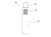
- Legal status (The legal status is an assumption and is not a legal conclusion. Google has not performed a legal analysis and makes no representation as to the accuracy of the status listed.)
- Ceased
Links
Images













Classifications
-
- A—HUMAN NECESSITIES
- A47—FURNITURE; DOMESTIC ARTICLES OR APPLIANCES; COFFEE MILLS; SPICE MILLS; SUCTION CLEANERS IN GENERAL
- A47L—DOMESTIC WASHING OR CLEANING; SUCTION CLEANERS IN GENERAL
- A47L9/00—Details or accessories of suction cleaners, e.g. mechanical means for controlling the suction or for effecting pulsating action; Storing devices specially adapted to suction cleaners or parts thereof; Carrying-vehicles specially adapted for suction cleaners
Definitions
- the present invention relates to a vacuum cleaner head and a vacuum cleaner.
- a vacuum cleaner equipped with a rotating brush is known as a vacuum cleaner head (nozzle head) that absorbs dust and other debris on the cleaning surface.
- the vacuum cleaner scrapes dust on the cleaning surface by rotating the rotating brush of the nozzle head that moves in the front-rear direction by the user's operation, and sucks the scraped dust.
- the front part of the head body that constitutes the nozzle head may come into contact with the wall. Since the nozzle head is allowed to move in the front-rear direction, the head body may repeatedly touch the wall when sucking dust near the wall (dust at the boundary between the wall and the cleaning surface). .. At this time, the head body strongly collides with the wall depending on the force of the user's operation.
- the head body If the head body collides with the wall, the head body can be damaged.
- the vacuum cleaner head body (nozzle head) disclosed in Patent Document 1 is provided with elastic rubber bumpers on the front portion and the left and right side portions.
- the bumper comes into contact with (collision) with the wall or the like. That is, the head body itself does not come into contact (collision) with a wall or the like. As a result, damage to the head body and the like is suppressed.
- An object of the present invention is to realize a vacuum cleaner head that prevents the head body from coming into contact with surrounding objects and improves the operability of the vacuum cleaner.
- the vacuum cleaner head prevents the head body that houses the rotating brush that collects dust on the cleaning surface and the head body mounted on the cleaning surface from coming into contact with objects around the head body.
- the protective member comprises a rotating shaft arranged on the head body and a rotating body rotatably attached to the rotating shaft.
- the present invention prevents the head body from coming into contact with surrounding objects and improves the operability of the vacuum cleaner.
- FIG. 1 It is a front perspective view which shows the embodiment of the vacuum cleaner which concerns on this invention. It is a front perspective view of the head for a vacuum cleaner provided in the vacuum cleaner of FIG. It is a rear perspective view of the head for a vacuum cleaner of FIG. It is a front view of the head for a vacuum cleaner of FIG. It is a rear view of the head for a vacuum cleaner of FIG. It is a top view of the head for a vacuum cleaner of FIG. It is a bottom view of the head for a vacuum cleaner of FIG. It is a right side view of the head for a vacuum cleaner of FIG. It is a left side view of the head for a vacuum cleaner of FIG. It is a partial cross-sectional view of a plane in the vacuum cleaner of FIG. FIG.
- FIG. 8 is a partial cross-sectional view of a side surface of the vacuum cleaner head of FIG. It is a front perspective view of the main body for a vacuum cleaner provided in the vacuum cleaner of FIG. It is a rear perspective view of the main body for a vacuum cleaner of FIG. It is a front view of the main body for a vacuum cleaner of FIG. It is a rear view of the main body for a vacuum cleaner of FIG. It is a top view of the main body for a vacuum cleaner of FIG. It is a bottom view of the main body for a vacuum cleaner of FIG. It is a right side view of the main body for a vacuum cleaner of FIG. It is a left side view of the main body for a vacuum cleaner of FIG. FIG.
- FIG. 12 is a reference rear view showing a transparent portion or a translucent portion of the vacuum cleaner main body of FIG. It is an overall view of the handle provided in the vacuum cleaner of FIG. It is a schematic diagram which shows the state which the vacuum cleaner of FIG. 1 is located near a wall. It is a schematic diagram which shows another example of the state which the vacuum cleaner of FIG. 1 is located near a wall. It is a side view which shows the other embodiment of the vacuum cleaner which concerns on this invention.
- FIG. 6 is an overall configuration diagram of a handle provided in the vacuum cleaner of FIG. 24. It is a partially disassembled perspective view of the vacuum cleaner of FIG. 24.
- each direction of up, down, left and right is defined with reference to the front. That is, the upper part with respect to the front is “upper”, the lower part with respect to the front is “lower”, the right with respect to the front is “right (right)”, and the left with respect to the front is “left (left)”.
- FIG. 1 is a front perspective view showing an embodiment of a vacuum cleaner according to the present invention (hereinafter referred to as “first embodiment”).
- Vacuum cleaner 1 sucks up dust and other debris on the cleaning surface.
- the vacuum cleaner 1 includes a vacuum cleaner head (suction port for an electric vacuum cleaner) 10, a universal joint portion 20, a vacuum cleaner main body (main body for an electric vacuum cleaner) 30, and a handle 40.
- FIG. 2 is a front perspective view of the vacuum cleaner head 10.
- FIG. 3 is a rear perspective view of the vacuum cleaner head 10.
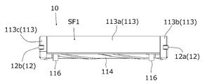
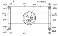
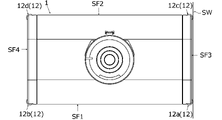
- FIG. 4 is a front view of the vacuum cleaner head 10.
- FIG. 5 is a rear view of the vacuum cleaner head 10.
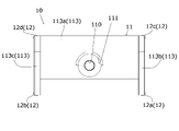
- FIG. 6 is a plan view of the vacuum cleaner head 10.
- FIG. 7 is a bottom view of the vacuum cleaner head 10.
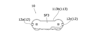
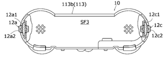
- FIG. 8 is a right side view of the vacuum cleaner head 10.
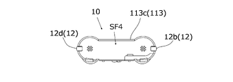
- FIG. 9 is a left side view of the vacuum cleaner head 10.
- the vacuum cleaner head 10 absorbs dust and other debris on the cleaning surface.
- the vacuum cleaner head 10 is a structure that faces the cleaning surface and sucks dust during use (during cleaning).
- the shape of the vacuum cleaner head 10 is substantially rectangular in a plan view.
- the vacuum cleaner head 10 is connected to the vacuum cleaner main body 30 via the universal joint portion 20.
- the vacuum cleaner head 10 includes a head body 11 and a protective member 12.
- the head body 11 accommodates a rotating brush (first rotating brush 114, second rotating brush 115) that scrapes off dust on the cleaning surface.
- the head body 11 includes a suction port 110, a mounting port 111, a suction portion 112, a cover body 113, a rotating brush (first rotating brush 114, second rotating brush 115), and a first hover brush 116.
- a second hover brush 117, casters (first caster 118a, second caster 118b), and a safety caster 119 are provided.
- the suction port 110 is a passage (flow path) through which dust collected by the first rotating brush 114 and the second rotating brush 115 and collected in the suction unit 112 passes.
- the suction port 110 is arranged at a position substantially in the center of the head main body 11 and overlapping with the mounting port 111.
- the mounting port 111 is a hole to which the universal joint portion 20 is mounted.
- the mounting port 111 is arranged substantially in the center of the head body 11. Inside the mounting port 111, suction ports 110 are concentrically arranged.
- the suction unit 112 is a space in which dust scraped off by the first rotating brush 114 and the second rotating brush 115 is collected.
- the dust collected in the suction unit 112 is stored in the dust box 32 (see FIG. 13) of the vacuum cleaner main body 30 via the suction port 110 by the suction force of a suction motor (not shown) described later.
- the cover body 113 houses the first rotating brush 114 and the second rotating brush 115 inside.
- the cover body 113 includes an upper cover 113a, a side cover 113b, and a side cover 113c.
- the upper cover 113a is provided with a suction port 110 in the substantially center of the plan view.
- the upper cover 113a covers the first rotating brush 114 and the second rotating brush 115 from above.
- the side cover 113b is attached to the right end of the upper cover 113a.
- a first caster 118a is attached to substantially the center of the lower surface of the side cover 113b.
- the side cover 113c is attached to the left end of the upper cover 113a.
- a second caster 118b is attached to substantially the center of the lower surface of the side cover 113c.
- the rotating brush is housed in the cover body 113.
- the rotating brush is a brush that extends in the left-right direction.
- the rotary brush includes a first rotary brush 114 and a second rotary brush 115.
- Each of the first rotating brush 114 and the second rotating brush 115 partially abuts (grounds / contacts) with the cleaning surface while rotating, and dust and the like on the cleaning surface and the cleaning surface are fluffy.
- dust such as hair and food debris that has entered the inside of the hair feet is scraped out and collected in the suction unit 112.
- the shape, size, and mass of the first rotating brush 114 are the same as the shape, size, and mass of the second rotating brush 115, respectively.
- the second rotating brush 115 rotates in the opposite direction to the rotation direction of the first rotating brush 114.
- the first rotating brush 114 is attached to the first rotating shaft (not shown) and is housed inside the cover body 113 (upper cover 113a).
- the first rotary brush 114 rotates with the rotation of the first rotary shaft due to the rotary drive of the drive motor (not shown).
- the first rotating brush 114 is arranged on the front side of the head main body 11.
- the second rotating brush 115 is attached to the second rotating shaft (not shown) and is housed inside the cover body 113 (upper cover 113a).
- the second rotary brush 115 rotates with the rotation of the second rotary shaft due to the rotary drive of the drive motor (not shown).
- the second rotating brush 115 is arranged on the back surface side of the head main body 11.
- the first hover brush 116 is arranged at both left and right ends of the first rotating brush 114 and rotates together with the first rotating brush 114.
- the first hover brush 116 reduces the frictional force between the first rotating brush 114 and the cleaning surface.
- the second hover brush 117 is arranged at the left and right ends of the second rotating brush 115 and rotates together with the second rotating brush 115.
- the second hover brush 117 reduces the frictional force between the second rotating brush 115 and the cleaning surface.
- the first caster 118a is attached to the head body 11 and rotates along the traveling direction of the head body 11.
- the first caster 118a is rotatable in all directions on the cleaning surface.
- the first caster 118a is arranged below the side cover 113b.
- the first caster 118a is, for example, a wheel type caster.
- the first caster 118a is arranged at an intermediate position between the first rotating brush 114 and the second rotating brush 115. That is, the first caster 118a is arranged at a position equidistant from each of the first rotating brush 114 and the second rotating brush 115.
- the second caster 118b is attached to the head body 11 and rotates along the traveling direction of the head body 11.
- the second caster 118b is rotatable in all directions on the cleaning surface.
- the second caster 118b is arranged below the side cover 113c.
- the second caster 118b is, for example, a wheel type caster.
- the second caster 118b is arranged at an intermediate position between the first rotating brush 114 and the second rotating brush 115. That is, the second caster 118b is arranged at a position equidistant from each of the first rotating brush 114 and the second rotating brush 115.
- the shape, size, and mass of the first caster 118a are the same as the shape, size, and mass of the second caster 118b, respectively.
- the direction of the line (virtual line) connecting the first caster 118a and the second caster 118b is parallel to the extending direction of the first rotating brush 114 and the extending direction of the second rotating brush 115.
- the safety caster 119 is attached to the lower part of the head body 11.
- the safety caster 119 can move up and down.
- Safety casters 119 are wheeled casters that can rotate in the front-back direction.
- the safety caster 119 retracts (retracts) upward when the vacuum cleaner head 10 is mounted on the cleaning surface (hereinafter referred to as “mounted state”).
- the drive motor (not shown) is in an energized state (hereinafter referred to as “energized state") when it is in the mounted state.
- the drive motor in the energized state drives the first rotary brush 114 and the second rotary brush 115.
- the driven first rotating brush 114 and the second rotating brush 115 rotate.
- the safety caster 119 moves forward (advances) downward when the vacuum cleaner head 10 is separated from the cleaning surface (hereinafter referred to as "separated state").
- the drive motor When the drive motor is in the separated state, the energized state is released (non-energized state).
- the drive motor in the non-energized state does not drive the first rotary brush 114 and the second rotary brush 115.
- the undriven first rotating brush 114 and the second rotating brush 115 do not rotate. That is, the rotation of the first rotating brush 114, which was driven and rotated in the energized state, and the rotation of the second rotating brush 115 stop in the non-energized state.
- the portion of the head body 11 represented in the front view of the vacuum cleaner head 10 is an example of the first surface portion SF1 in the present invention. That is, the first surface portion SF1 is composed of a part of the upper cover 113a, a part of the side cover 113b, and a part of the side cover 113c.
- the portion of the head body 11 represented in the rear view of the vacuum cleaner head 10 is an example of the second surface portion SF2 in the present invention. That is, the second surface portion SF2 is composed of a part of the upper cover 113a, a part of the side cover 113b, and a part of the side cover 113c. The second surface portion SF2 is arranged so as to face the first surface portion SF1.
- the portion of the head body 11 represented in the right side view of the vacuum cleaner head 10 is an example of the third surface portion SF3 in the present invention. That is, the third surface portion SF3 is composed of a part of the side cover 113b. The third surface portion SF3 is arranged so as to be connected to each of the first surface portion SF1 and the second surface portion SF2.
- the portion of the head body 11 represented in the left side view of the vacuum cleaner head 10 is an example of the fourth surface portion SF4 in the present invention. That is, the fourth surface portion SF4 is composed of a part of the side cover 113c. The fourth surface portion SF4 faces the third surface portion SF3 and is arranged so as to be connected to each of the first surface portion SF1 and the second surface portion SF2.
- the protective member 12 prevents the vacuum cleaner head 10 placed on the cleaning surface from coming into contact with an object around the vacuum cleaner head 10.
- the vacuum cleaner head 10 includes a plurality of protective members 12. That is, for example, the protective member 12 includes a first protective member 12a, a second protective member 12b, a third protective member 12c, and a fourth protective member 12d.
- the shape, size, and mass of the first protective member 12a are the shape, size, and mass of the second protective member 12b, the shape, size, and mass of the third protective member 12c, and the shape of the fourth protective member 12d. It is the same in size and mass.
- the "peripheral object” is an object that comes into contact with the protective member 12 of the vacuum cleaner head 10.
- Peripheral objects are, for example, walls such as rooms or corridors cleaned by the vacuum cleaner 1, TV boards and other furniture installed in these rooms and the like.
- the peripheral object is an object having a size such that two adjacent protective members 12 come into contact with each other at the same time.
- protective member 12 when it is not necessary to separately explain the first protective member 12a, the second protective member 12b, the third protective member 12c, and the fourth protective member 12d, each of them is collectively referred to as "protective member 12".
- FIG. 10 is a partial cross-sectional view of a plane of the vacuum cleaner 1.
- FIG. 11 is a partial cross-sectional view of a side surface of the vacuum cleaner head 10. The following description is also referred to in FIG. 2-9.
- the first protective member 12a cooperates with the second protective member 12b to prevent the first surface portion SF1 from coming into contact with surrounding objects, and cooperates with the third protective member 12c to prevent the third surface portion SF3 from coming into contact with the surrounding objects. Prevents contact with objects.
- the first protective member 12a includes a rotating shaft 12a1 and a rotating body 12a2. The first protective member 12a is arranged at the boundary between the adjacent first surface portion SF1 and the third surface portion SF3.
- the rotating shaft 12a1 is a shaft on which the rotating body 12a2 rotates.
- the rotating shaft 12a1 is arranged (accommodated) in the side cover 113b.
- the rotating shaft 12a1 is arranged (accommodated) in the head main body 11.
- the axial direction of the rotating shaft 12a1 is the direction perpendicular to the cleaning surface in the mounted state. That is, for example, the rotating shaft 12a1 is a shaft extending in the vertical direction in the mounted state.
- the rotating body 12a2 rotates about the rotation shaft 12a1.
- the rotating body 12a2 has a columnar shape.
- the rotating body 12a2 includes an insertion hole through which the rotating shaft 12a1 is inserted.
- the rotating body 12a2 is rotatably attached around the rotating shaft 12a1.
- the rotating body 12a2 is arranged (accommodated) in the side cover 113b with a part exposed.
- the rotating shaft 12a1 is arranged (accommodated) in the head body 11 with a part exposed.
- the rotating body 12a2 is an elastic material such as an elastomer.
- the rotating body 12a2 also serves as a cushion when it comes into contact with a surrounding object.
- the second protective member 12b cooperates with the first protective member 12a to prevent the first surface portion SF1 from coming into contact with surrounding objects, and cooperates with the fourth protective member 12d to prevent the fourth surface portion SF4 from coming into contact with surrounding objects. Prevents contact with objects.
- the second protective member 12b includes a rotating shaft 12b1 and a rotating body 12b2. The second protective member 12b is arranged at the boundary between the adjacent first surface portion SF1 and the fourth surface portion SF4.
- the rotating shaft 12b1 is a shaft on which the rotating body 12b2 rotates.
- the rotating shaft 12b1 is arranged (accommodated) in the side cover 113c.
- the rotating shaft 12b1 is arranged (accommodated) in the head main body 11.
- the axial direction of the rotating shaft 12b1 is the direction perpendicular to the cleaning surface in the mounted state. That is, for example, the rotating shaft 12b1 is a shaft extending in the vertical direction in the mounted state.
- the rotating body 12b2 rotates about the rotation shaft 12b1.
- the rotating body 12b2 is cylindrical.
- the rotating body 12b2 includes an insertion hole through which the rotating shaft 12b1 is inserted.
- the rotating body 12b2 is rotatably attached around the rotating shaft 12b1.
- the rotating body 12b2 is arranged (accommodated) in the side cover 113c with a part exposed.
- the rotating shaft 12b1 is arranged (accommodated) in the head body 11 with a part exposed.
- the rotating body 12b2 is an elastic material such as an elastomer.
- the rotating body 12b2 also serves as a cushion when it comes into contact with a surrounding object.
- the third protective member 12c cooperates with the fourth protective member 12d to prevent the second surface portion SF2 from coming into contact with surrounding objects, and cooperates with the first protective member 12a to prevent the third surface portion SF3 from coming into contact with the surrounding objects. Prevents contact with objects.
- the third protective member 12c includes a rotating shaft 12c1 and a rotating body 12c2. The third protective member 12c is arranged at the boundary between the adjacent second surface portion SF2 and the third surface portion SF3.
- the rotating shaft 12c1 is a shaft on which the rotating body 12c2 rotates.
- the rotating shaft 12c1 is arranged (accommodated) in the side cover 113b.
- the rotating shaft 12c1 is arranged (accommodated) in the head main body 11.
- the axial direction of the rotating shaft 12c1 is the direction perpendicular to the cleaning surface in the mounted state. That is, for example, the rotating shaft 12c1 is a shaft extending in the vertical direction in the mounted state.
- the rotating body 12c2 rotates about the rotation shaft 12c1.
- the rotating body 12c2 is cylindrical.
- the rotating body 12c2 includes an insertion hole through which the rotating shaft 12c1 is inserted.
- the rotating body 12c2 is rotatably attached around the rotating shaft 12c1.
- the rotating body 12c2 is arranged (accommodated) in the side cover 113b with a part exposed.
- the rotating shaft 12c1 is arranged (accommodated) in the head body 11 with a part exposed.
- the rotating body 12c2 is an elastic material such as an elastomer.
- the rotating body 12c2 also serves as a cushion when it comes into contact with a surrounding object.
- the fourth protective member 12d cooperates with the third protective member 12c to prevent the second surface portion SF2 from coming into contact with surrounding objects, and cooperates with the second protective member 12b to prevent the fourth surface portion SF4 from coming into contact with surrounding objects. Prevents contact with objects.
- the fourth protective member 12d includes a rotating shaft 12d1 and a rotating body 12d2. The fourth protective member 12d is arranged at the boundary between the adjacent second surface portion SF2 and the fourth surface portion SF4.
- the rotating shaft 12d1 is a shaft on which the rotating body 12d2 rotates.
- the rotating shaft 12d1 is arranged (accommodated) in the side cover 113c.
- the rotating shaft 12d1 is arranged (accommodated) in the head main body 11.
- the axial direction of the rotating shaft 12d1 is the direction perpendicular to the cleaning surface in the mounted state. That is, for example, the rotating shaft 12d1 is a shaft extending in the vertical direction in the mounted state.
- the rotating body 12d2 rotates about the rotation shaft 12d1.
- the rotating body 12d2 is cylindrical.
- the rotating body 12d2 includes an insertion hole through which the rotating shaft 12d1 is inserted.
- the rotating body 12d2 is rotatably attached around the rotating shaft 12d1.
- the rotating body 12d2 is arranged (accommodated) in the side cover 113c with a part exposed.
- the rotating shaft 12d1 is arranged (accommodated) in the head body 11 with a part exposed.
- the rotating body 12d2 is an elastic material such as an elastomer.
- the rotating body 12d2 also serves as a cushion when it comes into contact with a surrounding object.
- the configuration of the first protective member 12a is common to the configuration of the second protective member 12b, the configuration of the third protective member 12c, and the configuration of the fourth protective member 12d.
- the axial direction of the rotary shaft 12a1 is parallel to the axial direction of the rotary shaft 12b1, the axial direction of the rotary shaft 12c1, and the axial direction of the rotary shaft 12d1.
- the axial directions of the rotation axes (rotational shafts 12a1, 12b1, 12c1, 12d1) for each of the protective members 12a-12d are parallel to each other.
- each of the protective members 12a-12d is arranged at the boundary portion of the continuous (adjacent) surface portions (any two of SF1-SF4).
- each protective member 12a-12d is arranged at the four corners of the head main body 11. Furthermore, the height positions of the protective members 12a-12d arranged on the head body 11 are the same. That is, for example, when the head body 11 (vacuum cleaner head 10) is placed on a flat cleaning surface (straight cleaning surface), the height positions of the protective members 12a-12d from the respective cleaning surfaces ( The distance from the cleaning surface) is the same.
- the universal joint portion 20 connects the vacuum cleaner head 10 and the vacuum cleaner main body 30.
- the universal joint portion 20 enables the vacuum cleaner main body 30 to freely tilt at an arbitrary angle with respect to the vacuum cleaner head 10.
- One end (lower end) of the universal joint portion 20 is attached to the attachment port 111. That is, the universal joint portion 20 is attached to substantially the center of the upper part of the vacuum cleaner head 10. One end of the universal joint portion 20 is arranged at a position where it overlaps with the suction port 110 in a plan view. The axis (axis) of the suction port 110 coincides with the axis of the universal joint portion 20.
- the other end (upper end) of the universal joint portion 20 is attached to the lower end of the vacuum cleaner main body 30.
- the axis of the universal joint portion 20 coincides with the axis of the vacuum cleaner main body 30. That is, the axis of the universal joint portion 20 is located on the axis of the vacuum cleaner main body 30.
- the vacuum cleaner main body 30 is located on the axis (axis) of the suction port 110 and is freely tilted at an arbitrary angle with respect to the vacuum cleaner head 10.
- the universal joint portion 20 houses a flexible member (not shown) such as a bellows-shaped hose inside.
- the flexible member is connected to the suction port 110 and the lower end of the vacuum cleaner main body 30.
- the flexible member constitutes a passage (flow path) through which dust passing through the suction port 110 passes toward the vacuum cleaner main body 30.
- the other end of the universal joint portion 20 and the flexible member are detachable from the lower end of the vacuum cleaner main body 30.
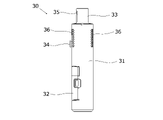
- FIG. 12 is a front perspective view of the vacuum cleaner main body 30.
- FIG. 13 is a rear perspective view of the vacuum cleaner main body 30.
- FIG. 14 is a front view of the vacuum cleaner main body 30.
- FIG. 15 is a rear view of the vacuum cleaner main body 30.
- FIG. 16 is a plan view of the vacuum cleaner main body 30.
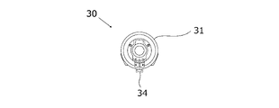
- FIG. 17 is a bottom view of the vacuum cleaner main body 30.
- FIG. 18 is a right side view of the vacuum cleaner main body 30.
- FIG. 19 is a left side view of the vacuum cleaner main body 30.
- FIG. 20 is a reference diagram showing a transparent portion or a translucent portion of the vacuum cleaner main body 30.
- the vacuum cleaner main body 30 houses a suction motor (not shown), a battery (not shown), and the like, which will be described later.
- a handle 40 (see FIG. 1) can be attached to and detached from the vacuum cleaner main body 30.
- One end (lower end) of the vacuum cleaner main body 30 is connected to the universal joint portion 20 (see FIG. 1).
- the other end (upper end) of the vacuum cleaner body 30 is connected to the handle 40.
- the vacuum cleaner main body 30 has a substantially tubular shape.
- the vacuum cleaner main body 30 includes a main body portion 31, a dust box 32, a handle attachment / detachment portion 33, an engagement portion 34, a handle removal outer surface 35, an exhaust port 36, a suction motor (not shown), and a battery (not shown). (Illustrated) and.
- the main body 31 accommodates the dust box 32, the suction motor, and the battery. One end (lower end) of the main body 31 is connected to the universal joint 20 (see FIG. 1).
- the shape composed of the main body 31 and the dust box 32 is substantially cylindrical.
- the dust box 32 is a box that is scraped off by the first rotating brush 114 and the second rotating brush 115, sucked by a suction motor, and passed through the suction port 110 to collect dust on the cleaning surface.
- the dust box 32 is detachably attached (accommodated) to the main body 31.
- Some of the members constituting the dust box 32 are made of, for example, transparent or translucent plastic (see FIG. 20).
- a part of the members constituting the dust box 32 is exposed to the outside of the main body 31. That is, a part of the dust box 32 is visible from the outside of the main body 31. That is, the dust collected inside the dust box 32 can be visually recognized from the outside of the vacuum cleaner main body 30.
- the dust collected inside the dust box 32 is discarded by the user to the outside of the dust box 32.
- the user removes the dust box 32 from the main body 31.
- the user removes a part of the member of the dust box 32 from the member that houses the dust.
- the user discharges the dust from the opening of the member by tilting the member for accommodating the dust.
- the "user” is the user (operator) of the vacuum cleaner 1.
- the handle attachment / detachment portion 33 attaches (attaches) the handle 40 detachably.
- the handle attachment / detachment portion 33 is arranged at the other end (upper end) of the main body portion 31.
- the handle attachment / detachment portion 33 includes an insertion port 331.
- the insertion port 331 is an opening into which the insertion portion 412 (see FIG. 21) of the handle 40 is inserted.
- the engaging portion 34 engages with the guide portion 4221 (see FIG. 25) of the second handle 42 (see FIG. 25), which will be described later, among the handles 40.
- the engaging portion 34 is arranged on the outer peripheral surface of the main body portion 31.
- the engaging portion 34 is arranged side by side on the outer peripheral surface of the main body portion 31 in the axial direction (vertical direction) of the main body portion 31 with the portion exposed from the main body portion 31 of the dust box 32.
- the handle removal outer surface 35 is used when the user removes the handle 40 attached to the handle attachment / detachment portion 33.
- the handle removal outer surface 35 is, for example, a pressing type button.
- the handle removal outer surface 35 is attached to, for example, the handle attachment / detachment portion 33. With the handle 40 attached to the handle attachment / detachment portion 33, the user pulls the handle 40 in a direction away from the vacuum cleaner main body 30 while pressing the handle removal outer portion 35, so that the handle 40 becomes the handle attachment / detachment portion 33 ( It is removed from the vacuum cleaner body 30).
- the exhaust port 36 is sucked by a suction motor and discharges the air that has passed through the dust box 32 to the outside of the main body 31.
- the exhaust port 36 is a plurality of openings arranged on the outer periphery of the main body 31, and exhausts the air inside the main body 31 to the outside.
- the suction motor sucks air by driving.
- the suction motor is housed in the main body 31.
- the battery is a power source that drives the drive motor and the suction motor.
- the battery is housed (attached) in the main body 31.
- FIG. 21 is an overall view of the handle 40. The following description will also be referred to in FIG.
- the handle 40 is gripped by the user during use. That is, the user grips the handle 40 and operates the vacuum cleaner 1.
- the handle 40 is detachably attached (attached) to the handle attachment / detachment portion 33.
- the handle 40 in the first embodiment is a rod-shaped first handle 41.
- the first handle 41 is gripped by the user during use. That is, the user grips the first handle 41 and operates the vacuum cleaner 1.
- the first handle 41 is, for example, cylindrical.
- the first handle 41 extends upward from the handle attachment / detachment portion 33 (vacuum cleaner main body 30).
- the axis (axis) of the first handle 41 in the state of being attached to the handle attachment / detachment portion 33 coincides with the axis of the universal joint portion 20.
- the first handle 41 includes a grip portion 411, an insertion portion 412, and an operation portion 413.
- the grip portion 411 is gripped by the user.
- the grip portion 411 is a portion between the insertion portion 412 and the operation portion 413.
- the insertion portion 412 is inserted into the insertion port 331 (see FIG. 12) of the handle attachment / detachment portion 33.
- the insertion portion 412 is arranged on one end side (lower end side) of the first handle 41.
- the first handle 41 is attached (attached) to the handle attachment / detachment portion 33 (vacuum cleaner main body 30).
- the operation unit 413 switches the power of the vacuum cleaner 1 on and off. That is, the operation unit 413 controls the operation of the suction motor.
- the operation unit 413 is, for example, a pressing type operation button.
- the operation unit 413 is arranged on the other end side (upper end side) of the first handle 41. The operation unit 413 is operated by the user when the cleaning is started (when the cleaning that has been temporarily suspended is resumed) and when the cleaning is finished (when the cleaning is temporarily interrupted).
- FIG. 22 is a schematic diagram showing a state in which the vacuum cleaner 1 is located near the wall. The figure shows a state in which the front side of the vacuum cleaner head 10 is in contact with a surrounding object.
- front wall a front wall
- the protective member 12 rotating body 12a2 of the first protective member 12a (FIG. FIG. 10) and the rotating body 12b2 (see FIG. 10) of the second protective member 12b come into contact with the front wall FW. That is, when the front side of the vacuum cleaner head 10 is in contact with the front wall FW, the head body 11 (first surface portion SF1) does not come into contact with the front wall FW. That is, when the front side of the vacuum cleaner head 10 is in contact with the front wall FW, a gap is formed between the front wall FW and the head main body 11 (first surface portion SF1). In other words, the first protective member 12a and the second protective member 12b prevent the first surface portion SF1 from coming into contact with the front wall FW.
- the rotating body 12a2 of the first protective member 12a and the rotating body 12b2 of the second protective member 12b are attached to the front wall FW.
- the shape of the rotating body 12a2 is the same as the shape of the rotating body 12b2.
- the axial direction of the rotating shaft 12a1 of the rotating body 12a2 is parallel to the axial direction of the rotating shaft 12b1 of the rotating body 12b2. Therefore, when the vacuum cleaner head 10 is moved in the left-right direction by the user, the rotating bodies 12a2 and 12b2 rotate in contact with the front wall FW. As a result, the movement of the vacuum cleaner head 10 in the left-right direction becomes smooth.
- back wall a back wall
- the protective member 12 the rotating body 12c2 of the third protective member 12c and the rotating body 12d2 of the fourth protective member 12d
- the head body 11 does not come into contact with the back wall.
- the third protective member 12c and the fourth protective member 12d prevent the second surface portion SF2 from coming into contact with the back wall.
- the rotating body 12c2 of the third protective member 12c and the rotating body 12d2 of the fourth protective member 12d come into contact with the back wall. ..
- the shape of the rotating body 12c2 is the same as the shape of the rotating body 12d2.
- the axial direction of the rotating shaft 12c1 of the rotating body 12c2 is parallel to the axial direction of the rotating shaft of the rotating shaft 12d1 of the rotating body 12d2. Therefore, when the vacuum cleaner head 10 is moved in the left-right direction by the user, the rotating bodies 12c2 and 12d2 rotate in contact with the back wall. As a result, the movement of the vacuum cleaner head 10 in the left-right direction becomes smooth.
- FIG. 23 is a schematic view showing another example of the state where the vacuum cleaner 1 is located near the wall. The figure shows a state in which the right side surface of the vacuum cleaner head 10 is in contact with a surrounding object.
- the protective member 12 rotates body 12a2 of the first protective member 12a (FIG. 10) and the rotating body 12c2 (see FIG. 10) of the third protective member 12c come into contact with the side wall SW. That is, when the right side of the vacuum cleaner head 10 is in contact with the side wall SW, the head body 11 (third surface portion SF3) does not come into contact with the side wall SW. That is, when the right side of the vacuum cleaner head 10 is in contact with the side wall SW, a gap is formed between the side wall SW and the head main body 11 (third surface portion SF3). In other words, the first protective member 12a and the third protective member 12c prevent the third surface portion SF3 from coming into contact with the side wall SW.
- the rotating body 12a2 of the first protective member 12a and the rotating body 12c2 of the third protective member 12c are in contact with the side wall SW.
- the shape of the rotating body 12a2 is the same as the shape of the rotating body 12c2.
- the axial direction of the rotating shaft 12a1 of the rotating body 12a2 is parallel to the axial direction of the rotating shaft 12c1 of the rotating body 12c2. Therefore, when the vacuum cleaner head 10 is moved in the front-rear direction by the user, the rotating bodies 12a2 and 12c2 rotate in contact with the side wall SW. As a result, the movement of the vacuum cleaner head 10 from the front to the back becomes smooth.
- the second protective member 12b and the fourth protective member 12d prevent the fourth surface portion SF4 from coming into contact with the side wall SW.
- the rotating body 12b2 of the second protective member 12b and the rotating body 12d2 of the fourth protective member 12d are in contact with the side wall SW.
- the shape of the rotating body 12b2 is the same as the shape of the rotating body 12d2.
- the axial direction of the rotating shaft of the rotating body 12b2 is parallel to the axial direction of the rotating shaft of the rotating body 12d2. Therefore, when the vacuum cleaner head 10 is moved in the front-rear direction by the user, the rotating bodies 12b2 and 12d2 rotate in contact with the side wall SW. As a result, the movement of the vacuum cleaner head 10 from the front to the back becomes smooth.
- the vacuum cleaner head 10 when the vacuum cleaner head 10 is placed in the corner of the room and the front side and the right side surface side of the vacuum cleaner head 10 are in contact with the front wall FW and the side wall SW.
- the rotating body 12a2 of the first protective member 12a and the rotating body 12b2 of the second protective member 12b are in contact with the front wall FW
- the rotating body 12a2 of the first protective member 12a and the rotating body 12c of the third protective member 12c are in contact with each other. 12c2 comes into contact with the side wall SW. That is, the rotating body 12a2 of the first protective member 12a comes into contact with the front wall FW and the side wall SW.
- the first protective member 12a and the second protective member 12b prevent the first surface portion SF1 from coming into contact with the front wall FW, and the first protective member 12a and the third protective member 12c are the third surface portion. Prevents SF3 from coming into contact with the side wall SW.
- the vacuum cleaner head 10 includes a protective member 12. Even if the vacuum cleaner head 10 approaches a peripheral object such as a wall (for example, a front wall FW or a side wall SW) during cleaning and the protective member 12 comes into contact with a peripheral object, the head body 11 is still in the vicinity. Do not touch objects. As a result, the head body 11 is not damaged. Further, since the protective member 12 itself acts as a cushion, damage to surrounding objects is reduced.
- a peripheral object such as a wall (for example, a front wall FW or a side wall SW) during cleaning and the protective member 12 comes into contact with a peripheral object
- the head body 11 is still in the vicinity. Do not touch objects. As a result, the head body 11 is not damaged.
- the protective member 12 itself acts as a cushion, damage to surrounding objects is reduced.
- the protective member 12 is arranged at each corner of the head body 11 having a substantially rectangular shape. Therefore, even if the vacuum cleaner head 10 approaches a peripheral object such as a wall during cleaning and two adjacent protective members 12 come into contact with the peripheral object, the head body 11 does not come into contact with the peripheral object. As a result, the head body 11 is not damaged.
- the protective members 12 are arranged at the four corners of the head body 11 having a substantially rectangular shape. Therefore, even if the vacuum cleaner head 10 approaches the two walls and the protective member 12 comes into contact with one or both of the two walls in a place where there are two walls such as a corner of a room. The head body 11 does not touch either of the two walls. As a result, the head body 11 is not damaged.
- the protective member 12 includes a rotating shaft 12a1-12d1 and a rotating body 12a2-12d2 rotatably attached to each rotating shaft 12a1-12d1. Therefore, for example, when the front side of the vacuum cleaner head 10 is in contact with the front wall FW (peripheral object), the rotating body 12a2 of the first protective member 12a, the rotating body 12b2 of the second protective member 12b, and the like. Contact the front wall FW.
- the rotating bodies 12a2 and 12b2 rotate in contact with the front wall FW, so that the vacuum cleaner head 10 moves smoothly in the left-right direction. become. As a result, the operability of the vacuum cleaner 1 is improved.
- the place where the protective member is placed is not limited to the four corners of the head body. That is, for example, two or more protective members may be arranged on each surface portion of the first surface portion to the fourth surface portion. Further, in addition to the four corners of the head body, one or more may be arranged on each surface portion of the first surface portion to the fourth surface portion. That is, the number of protective members is not limited to "4".
- the shape of the head body is not limited to a substantially rectangular shape.
- FIG. 24 is a side view of the vacuum cleaner 100 of the second embodiment.
- a handle 40 (second handle 42) different from the first handle 41 is attached to the vacuum cleaner main body 30.
- the figure shows an example of a case where the gap nozzle 50 is attached to the other end of the vacuum cleaner main body 30 instead of the vacuum cleaner head 10 as an example of the case where the second handle 42 is used.
- the vacuum cleaner 100 includes a vacuum cleaner main body 30, a second handle 42 (handle 40), and a gap nozzle 50.
- the configuration of the vacuum cleaner main body 30 in the second embodiment is the same as the configuration of the vacuum cleaner main body 30 in the first embodiment. Therefore, the specific description of the vacuum cleaner main body 30 in the second embodiment will be omitted.
- FIG. 25 is an overall configuration diagram of the second handle 42.
- the function of the second handle 42 is the same as the function of the first handle 41 (handle 40). That is, the second handle 42 is gripped by the user during use. That is, the user grips the second handle 42 and operates the vacuum cleaner 100.
- the second handle 42 is detachably attached (attached) to the handle attachment / detachment portion 33 (see FIG. 26).
- the shape of the second handle 42 is different from the shape of the first handle 41. That is, the second handle 42 includes a grip body 421, a guide body 422, an insertion portion 423, a connecting body 424, and an operation portion 425 (see FIG. 26).
- the second handle 42 is smaller than the first handle 41.
- the second handle 42 is a handle when the vacuum cleaner 100 is used as a so-called handy type.
- the grip body 421 is gripped by the user during cleaning (during use).
- the grip body 421 is arranged between the guide body 422 and the connecting body 424.
- the grip body 421 is arranged on one end side of the connecting body 424.
- the guide body 422 is attached to and fixed to the vacuum cleaner main body 30.
- the guide body 422 is connected (arranged) to one end side (lower end side) (lower side of the paper surface in FIG. 25) of the grip body 421.
- the guide body 422 includes a guide portion 4221.
- the guide portion 4221 engages with the engaging portion 34 while being guided by the engaging portion 34 (see FIG. 26). By engaging the guide portion 4221 with the engaging portion 34, the position and orientation of the second handle 42 with respect to the vacuum cleaner main body 30 are determined.
- the insertion portion 423 is inserted into the insertion port 331 (see FIG. 12) of the handle attachment / detachment portion 33.
- the insertion portion 423 is arranged on the other end side of the connecting body 424.
- the second handle 42 is attached (attached) to the handle attachment / detachment portion 33 (vacuum cleaner main body 30).
- the shape of the insertion portion 423 of the second handle 42 is the same as the shape of the insertion portion 412 of the first handle 41. Therefore, the insertion portion 412 of the first handle 41 or the insertion portion 423 of the second handle 42 can be inserted into the insertion port 331 of the handle attachment / detachment portion 33.
- the connecting body 424 connects the gripping body 421 and the insertion portion 423.
- the connecting body 424 is connected (arranged) to the other end side (upper end side) of the grip body 421 (upper side of the paper surface in FIG. 25).
- the operation unit 425 switches the power of the vacuum cleaner 1 on and off. That is, the operation unit 425 controls the operation of the suction motor (not shown).
- the operation unit 425 is, for example, a pressing type operation button.
- the operation unit 425 is arranged on the guide body 422. The operation unit 425 is operated by the user when the cleaning is started (when the cleaning that has been temporarily suspended is resumed) and when the cleaning is finished (when the cleaning is temporarily interrupted).
- the user pulls the second handle 42 away from the vacuum cleaner main body 30 while pressing the handle removal outer surface 35 (see, for example, FIG. 15). Thereby, the second handle 42 can be removed from the handle attachment / detachment portion 33 (vacuum cleaner main body 30).
- the user can attach the first handle 41 to the handle attachment / detachment portion 33 (vacuum cleaner main body 30). That is, only one of the first handle 41 and the second handle 42 is selectively mounted on the handle attachment / detachment portion 33. In other words, the vacuum cleaner main body 30 is shared by the first handle 41 and the second handle 42.
- FIG. 26 is a partially disassembled perspective view of the vacuum cleaner 100.
- the figure shows a state in which the second handle 42 is removed from the vacuum cleaner main body 30.
- the illustration of the gap nozzle 50 is omitted.
- the user When attaching (attaching) the second handle 42 to the vacuum cleaner main body 30, the user inserts the insertion portion 423 into the insertion port 331 (handle attachment / detachment portion 33). At this time, when the insertion portion 423 is engaged while a part of the guide portion 4221 is guided by the engagement portion 34 and the insertion portion 423 is completely inserted into the insertion port 331, the entire guide portion 4221 is inserted. Engage with the engaging portion 34. By engaging the guide portion 4221 with the engaging portion 34, the strength of the vacuum cleaner 100 becomes higher than that in the case where the engaging portion 34 is not provided (in the case of cantilever).
- the gap nozzle 50 (see FIG. 24) is used when cleaning a part of the cleaning surface where it is difficult for the head body 11 (for example, see FIG. 1) to enter, such as the back of a TV board, or the top of a sofa. Be done. That is, for example, the gap nozzle 50 is a so-called attachment tool that can be attached to and detached from the vacuum cleaner main body 30. The gap nozzle 50 is attached to the lower end of the vacuum cleaner main body 30.
- the user When using the gap nozzle 50, the user removes the universal joint portion 20 and the vacuum cleaner head 10 in the first embodiment from the vacuum cleaner main body 30.
- the gap nozzle 50 is attached (mounted) to the vacuum cleaner main body 30 instead of the universal joint portion 20.
- the vacuum cleaner main body 30 of the vacuum cleaner according to the present invention only one of the first handle 41 and the second handle 42 having different shapes can be selectively mounted. It has a handle attachment / detachment portion 33. That is, the number of handle attachment / detachment portions 33 is one for the plurality of handles 40. That is, the handle attachment / detachment portion 33 is common to the different handles 40. Therefore, the vacuum cleaner main body 30 does not need to be provided with a handle attachment / detachment portion 33 for each different handle 40. Further, the vacuum cleaner according to the present invention has a structure in which a handy type handle (second handle) is not permanently installed.
- the vacuum cleaner according to the present invention can be optimized according to each usage mode depending on whether the first handle 41 is used or the second handle 42 is used.
- the vacuum cleaner main body 30 has an engaging portion 34. Therefore, when the second handle 42 is attached to the vacuum cleaner main body 30, the engaging portion 34 engages with the guide body 422 while being guided by the guide portion 4221 of the second handle 42. As for the strength of the vacuum cleaner 100, an appropriate strength can be ensured as compared with the case where the engaging portion 34 is not provided (in the case of cantilever).
- the handle is not limited to the first handle and the second handle. That is, for example, the vacuum cleaner main body 30 may have other handles detachable. That is, the number of handles that can be attached to and detached from the vacuum cleaner main body 30 is not limited to "2", and may be "3" or more.
- the shape / configuration of the second handle is not limited to the shape / configuration shown in the second embodiment. That is, for example, the second handle may have another shape / configuration as long as it has a shape / configuration different from that of the first handle.
- the universal joint portion and the vacuum cleaner body shown in the first embodiment are used as the vacuum cleaner body instead of the gap nozzle. It may be attached and used.
- Vacuum cleaner 10 Vacuum cleaner head 11 Head body 110 Suction port 111 Mounting port 112 Suction part 113 Cover body 113a Top cover 113b Side cover 113c Side cover 114 1st rotation brush 115 2nd rotation brush 116 1st hover brush 117th 2 Hover brush 118a 1st caster 118b 2nd caster 119 Safety caster 12 Protective member 12a 1st protective member 12a1 Rotating shaft 12a2 Rotating body 12b 2nd protective member 12b1 Rotating shaft 12b2 Rotating body 12c 3rd protective member 12c1 Rotating shaft 12c2 Rotation Body 12d 4th protective member 12d1 Rotating shaft 12d2 Rotating body 20 Flexible joint part 30 Main body for vacuum cleaner 31 Main body 32 Dust box 33 Handle attachment / detachment part 331 Insertion port 34 Engagement part 35 Handle removal outside 40 Handle 41 1st handle 411 Grip part 412 Insertion part 413 Operation part 42 Second handle 421 Grip body 422 Guide body 4221 Guide part 423
Landscapes
- Engineering & Computer Science (AREA)
- Mechanical Engineering (AREA)
- Nozzles For Electric Vacuum Cleaners (AREA)
Priority Applications (2)
| Application Number | Priority Date | Filing Date | Title |
|---|---|---|---|
| JP2022553361A JP7448999B2 (ja) | 2020-09-30 | 2020-09-30 | 掃除機用ヘッドと掃除機 |
| PCT/JP2020/037372 WO2022070369A1 (ja) | 2020-09-30 | 2020-09-30 | 掃除機用ヘッドと掃除機 |
Applications Claiming Priority (1)
| Application Number | Priority Date | Filing Date | Title |
|---|---|---|---|
| PCT/JP2020/037372 WO2022070369A1 (ja) | 2020-09-30 | 2020-09-30 | 掃除機用ヘッドと掃除機 |
Publications (1)
| Publication Number | Publication Date |
|---|---|
| WO2022070369A1 true WO2022070369A1 (ja) | 2022-04-07 |
Family
ID=80949990
Family Applications (1)
| Application Number | Title | Priority Date | Filing Date |
|---|---|---|---|
| PCT/JP2020/037372 Ceased WO2022070369A1 (ja) | 2020-09-30 | 2020-09-30 | 掃除機用ヘッドと掃除機 |
Country Status (2)
| Country | Link |
|---|---|
| JP (1) | JP7448999B2 (https=) |
| WO (1) | WO2022070369A1 (https=) |
Citations (3)
| Publication number | Priority date | Publication date | Assignee | Title |
|---|---|---|---|---|
| JPH0947394A (ja) * | 1995-08-08 | 1997-02-18 | Tec Corp | 電気掃除機の吸込口体 |
| JP2011045694A (ja) * | 2009-07-31 | 2011-03-10 | Fuji Heavy Ind Ltd | サイドブラシ装置を備えた自走式清掃ロボット |
| JP2016039858A (ja) * | 2014-08-12 | 2016-03-24 | 株式会社マキタ | ハンディクリーナ |
Family Cites Families (5)
| Publication number | Priority date | Publication date | Assignee | Title |
|---|---|---|---|---|
| JPH05329071A (ja) * | 1992-05-29 | 1993-12-14 | Tokyo Electric Co Ltd | 電気掃除機の吸込口体 |
| JP3457541B2 (ja) * | 1998-07-29 | 2003-10-20 | シャープ株式会社 | 電気掃除機用吸込口体 |
| JP2005000308A (ja) * | 2003-06-10 | 2005-01-06 | Toshiba Tec Corp | 吸込み口体及び電気掃除機 |
| JP3868954B2 (ja) * | 2003-12-22 | 2007-01-17 | 株式会社日立製作所 | 電気掃除機 |
| JP2007111158A (ja) * | 2005-10-19 | 2007-05-10 | Matsushita Electric Ind Co Ltd | 電気掃除機 |
-
2020
- 2020-09-30 WO PCT/JP2020/037372 patent/WO2022070369A1/ja not_active Ceased
- 2020-09-30 JP JP2022553361A patent/JP7448999B2/ja active Active
Patent Citations (3)
| Publication number | Priority date | Publication date | Assignee | Title |
|---|---|---|---|---|
| JPH0947394A (ja) * | 1995-08-08 | 1997-02-18 | Tec Corp | 電気掃除機の吸込口体 |
| JP2011045694A (ja) * | 2009-07-31 | 2011-03-10 | Fuji Heavy Ind Ltd | サイドブラシ装置を備えた自走式清掃ロボット |
| JP2016039858A (ja) * | 2014-08-12 | 2016-03-24 | 株式会社マキタ | ハンディクリーナ |
Also Published As
| Publication number | Publication date |
|---|---|
| JP7448999B2 (ja) | 2024-03-13 |
| JPWO2022070369A1 (https=) | 2022-04-07 |
Similar Documents
| Publication | Publication Date | Title |
|---|---|---|
| EP3646768B1 (en) | Vacuum cleaner | |
| KR100474083B1 (ko) | 다용도 진공청소기 | |
| CN107397506B (zh) | 吸尘器 | |
| CN102987983B (zh) | 自主清洁器具 | |
| EP2016882B1 (en) | Suction brush for vacuum cleaner | |
| JP2005323999A (ja) | ロボット掃除機 | |
| GB2430863A (en) | Dust collector having filter cleaning means | |
| CN106793903A (zh) | 机器人清洁器 | |
| WO2019044074A1 (ja) | 自律走行型掃除機 | |
| KR100405244B1 (ko) | 진공청소기의 흡입부 조립체 | |
| KR101917702B1 (ko) | 청소기 | |
| KR101208979B1 (ko) | 분리형 로봇 청소기 | |
| WO2022070370A1 (ja) | 掃除機用本体と掃除機 | |
| WO2022070369A1 (ja) | 掃除機用ヘッドと掃除機 | |
| JP2000070198A (ja) | 電気掃除機 | |
| JP5481087B2 (ja) | 吸口体及びこの吸口体を備えた電気掃除機 | |
| JP2013070838A (ja) | 電気掃除機 | |
| JP7249496B2 (ja) | 自律走行型掃除機 | |
| KR20200084213A (ko) | 브러쉬가 구비된 물걸레 겸용 청소기 | |
| JPH11309099A (ja) | 電気掃除機の吸口体及びこの吸口体を備えた電気掃除機 | |
| JP2019166255A (ja) | 吸込具及び電気掃除機 | |
| WO2020105223A1 (ja) | 吸込具および電気掃除機 | |
| JP2010273991A (ja) | 吸込口体および電気掃除機 | |
| JP7400858B2 (ja) | 掃除具、電気掃除機、及びコードレス型掃除機 | |
| JP3149160B2 (ja) | 電気掃除機の吸口体及びこれを備えた電気掃除機 |
Legal Events
| Date | Code | Title | Description |
|---|---|---|---|
| 121 | Ep: the epo has been informed by wipo that ep was designated in this application |
Ref document number: 20956297 Country of ref document: EP Kind code of ref document: A1 |
|
| ENP | Entry into the national phase |
Ref document number: 2022553361 Country of ref document: JP Kind code of ref document: A |
|
| NENP | Non-entry into the national phase |
Ref country code: DE |
|
| 122 | Ep: pct application non-entry in european phase |
Ref document number: 20956297 Country of ref document: EP Kind code of ref document: A1 |