WO2022065280A1 - 工作機械の制御装置 - Google Patents
工作機械の制御装置 Download PDFInfo
- Publication number
- WO2022065280A1 WO2022065280A1 PCT/JP2021/034514 JP2021034514W WO2022065280A1 WO 2022065280 A1 WO2022065280 A1 WO 2022065280A1 JP 2021034514 W JP2021034514 W JP 2021034514W WO 2022065280 A1 WO2022065280 A1 WO 2022065280A1
- Authority
- WO
- WIPO (PCT)
- Prior art keywords
- setting
- input
- interference check
- area
- item
- Prior art date
- Legal status (The legal status is an assumption and is not a legal conclusion. Google has not performed a legal analysis and makes no representation as to the accuracy of the status listed.)
- Ceased
Links
Images




Classifications
-
- G—PHYSICS
- G05—CONTROLLING; REGULATING
- G05B—CONTROL OR REGULATING SYSTEMS IN GENERAL; FUNCTIONAL ELEMENTS OF SUCH SYSTEMS; MONITORING OR TESTING ARRANGEMENTS FOR SUCH SYSTEMS OR ELEMENTS
- G05B19/00—Program-control systems
- G05B19/02—Program-control systems electric
- G05B19/18—Numerical control [NC], i.e. automatically operating machines, in particular machine tools, e.g. in a manufacturing environment, so as to execute positioning, movement or co-ordinated operations by means of program data in numerical form
- G05B19/406—Numerical control [NC], i.e. automatically operating machines, in particular machine tools, e.g. in a manufacturing environment, so as to execute positioning, movement or co-ordinated operations by means of program data in numerical form characterised by monitoring or safety
-
- G—PHYSICS
- G05—CONTROLLING; REGULATING
- G05B—CONTROL OR REGULATING SYSTEMS IN GENERAL; FUNCTIONAL ELEMENTS OF SUCH SYSTEMS; MONITORING OR TESTING ARRANGEMENTS FOR SUCH SYSTEMS OR ELEMENTS
- G05B19/00—Program-control systems
- G05B19/02—Program-control systems electric
- G05B19/18—Numerical control [NC], i.e. automatically operating machines, in particular machine tools, e.g. in a manufacturing environment, so as to execute positioning, movement or co-ordinated operations by means of program data in numerical form
- G05B19/406—Numerical control [NC], i.e. automatically operating machines, in particular machine tools, e.g. in a manufacturing environment, so as to execute positioning, movement or co-ordinated operations by means of program data in numerical form characterised by monitoring or safety
- G05B19/4061—Avoiding collision or forbidden zones
-
- G—PHYSICS
- G05—CONTROLLING; REGULATING
- G05B—CONTROL OR REGULATING SYSTEMS IN GENERAL; FUNCTIONAL ELEMENTS OF SUCH SYSTEMS; MONITORING OR TESTING ARRANGEMENTS FOR SUCH SYSTEMS OR ELEMENTS
- G05B19/00—Program-control systems
- G05B19/02—Program-control systems electric
- G05B19/18—Numerical control [NC], i.e. automatically operating machines, in particular machine tools, e.g. in a manufacturing environment, so as to execute positioning, movement or co-ordinated operations by means of program data in numerical form
- G05B19/409—Numerical control [NC], i.e. automatically operating machines, in particular machine tools, e.g. in a manufacturing environment, so as to execute positioning, movement or co-ordinated operations by means of program data in numerical form characterised by using manual data input [MDI] or by using control panel, e.g. controlling functions with the panel; characterised by control panel details or by setting parameters
-
- G—PHYSICS
- G05—CONTROLLING; REGULATING
- G05B—CONTROL OR REGULATING SYSTEMS IN GENERAL; FUNCTIONAL ELEMENTS OF SUCH SYSTEMS; MONITORING OR TESTING ARRANGEMENTS FOR SUCH SYSTEMS OR ELEMENTS
- G05B2219/00—Program-control systems
- G05B2219/30—Nc systems
- G05B2219/49—Nc machine tool, till multiple
- G05B2219/49141—Detect near collision and slow, stop, inhibit movement tool
-
- G—PHYSICS
- G05—CONTROLLING; REGULATING
- G05B—CONTROL OR REGULATING SYSTEMS IN GENERAL; FUNCTIONAL ELEMENTS OF SUCH SYSTEMS; MONITORING OR TESTING ARRANGEMENTS FOR SUCH SYSTEMS OR ELEMENTS
- G05B2219/00—Program-control systems
- G05B2219/30—Nc systems
- G05B2219/49—Nc machine tool, till multiple
- G05B2219/49143—Obstacle, collision avoiding control, move so that no collision occurs
-
- Y—GENERAL TAGGING OF NEW TECHNOLOGICAL DEVELOPMENTS; GENERAL TAGGING OF CROSS-SECTIONAL TECHNOLOGIES SPANNING OVER SEVERAL SECTIONS OF THE IPC; TECHNICAL SUBJECTS COVERED BY FORMER USPC CROSS-REFERENCE ART COLLECTIONS [XRACs] AND DIGESTS
- Y02—TECHNOLOGIES OR APPLICATIONS FOR MITIGATION OR ADAPTATION AGAINST CLIMATE CHANGE
- Y02P—CLIMATE CHANGE MITIGATION TECHNOLOGIES IN THE PRODUCTION OR PROCESSING OF GOODS
- Y02P90/00—Enabling technologies with a potential contribution to greenhouse gas [GHG] emissions mitigation
- Y02P90/02—Total factory control, e.g. smart factories, flexible manufacturing systems [FMS] or integrated manufacturing systems [IMS]
Definitions
- the present invention relates to a control device for a machine tool.
- Patent Document 1 a machine tool control device having a function of checking the interference between the tool and the auxiliary mechanism is known (for example, Patent Document 1). And 2).
- Patent Documents 1 and 2 the interference areas of the auxiliary mechanism and the tool are set by using the three-dimensional data of the auxiliary mechanism and the tool, the movement of the auxiliary mechanism and the tool is simulated, and whether or not the interference areas interfere with each other. Is checking.
- the shape and dimensions of the auxiliary mechanism used may vary from user to user. Further, even if the auxiliary mechanism is the same, the installation direction and the installation position may differ from user to user. Therefore, it is inconvenient because it takes time to set the interference area.
- One aspect of the present disclosure is a control device for a machine tool having a function of checking interference between a tool and an auxiliary mechanism on a table, from a storage unit that stores three-dimensional basic shape data and the basic shape data.
- An interference check area of the auxiliary mechanism is created, and the positions of a region setting unit that sets the interference check area within a predetermined setting area surrounding the auxiliary mechanism and a plurality of boundary surfaces of the interference check area are determined.
- the plurality of setting items include at least one non-essential item in which the input of the setting value is not essential, and the area setting unit includes an input unit in which the setting values of the plurality of setting items for the purpose are input by the operator.
- the interference check area is set based on the set value input to the input unit and there is an uninput item which is a non-essential item for which the set value is not input, the non-input item is used. It is a machine tool control device that sets the determined boundary surface at the end of the predetermined setting area.
- the machine tool 10 has a spindle 3 for holding a tool 2, a table 4 on which a work W is placed, a spindle motor 5 for rotating the spindle 3, and a spindle 3 with respect to the table 4.
- the Z-axis feed motor 6 that moves the table 4 in the Z direction
- the X-axis feed motor 7 and the Y-axis feed motor 8 that move the table 4 in the X and Y directions with respect to the spindle 3, and the motors 5, 6, and 7.
- a numerical control device 1 for controlling, 8 is provided.
- the Z direction is a direction along the longitudinal axis of the tool 2 held by the spindle 3.
- the X direction and the Y direction are directions orthogonal to the longitudinal axis of the tool 2 held by the spindle 3, and are orthogonal to each other.
- the Z direction is the vertical direction
- the X direction and the Y direction are the horizontal directions.
- the spindle 3 is arranged in the vertical direction and is movably supported in the vertical direction by a support mechanism (not shown).
- the tool 2 is held coaxially with the spindle 3 at the lower end of the spindle 3, and rotates and moves integrally with the spindle 3.
- the table 4 is horizontally arranged below the spindle 3.
- An auxiliary mechanism 9 for holding the work W is installed on the mounting surface 4a, which is the upper surface of the table 4.
- the auxiliary mechanism 9 is, for example, a jig for fixing the work W to the table 4, or an additional axis table for changing the posture of the work W with respect to the table 4.
- the feed motors 6, 7 and 8 are servo motors, respectively.
- the feed motors 7 and 8 move the tool 2 in the X and Y directions with respect to the table 4 by moving the table 4 in the X and Y directions.
- the operating range in the X direction is between both ends of the table 4 in the X direction
- the operating range in the Y direction is between both ends of the table 4 in the Y direction.
- the control device 1 includes a storage unit 11, an input unit 12, and a control unit 13.
- the storage unit 11 has a RAM, a ROM, and any other storage device.
- the input unit 12 has a touch panel, a mouse, a keyboard, and the like. The operator can perform various input operations to the control device 1 by using the input unit 12.
- control unit 13 controls the operations of the spindle 3 and the table 4 by transmitting control commands based on the machining program stored in the storage unit 11 to the motors 5, 6, 7, and 8.
- control unit 13 controls the operations of the spindle 3 and the table 4 by transmitting control commands to the motors 5, 6, 7, and 8 based on the input to the operation input device (not shown) by the operator. do.
- the control unit 13 is realized by at least one processor such as a central processing unit built in the control device 1.
- control device 1 includes an area setting unit 14 and an interference check unit 15 as a function of checking interference between the tool 2 and the auxiliary mechanism 9 during automatic or manual operation of the machine tool 10.
- the area setting unit 14 and the interference check unit 15 are realized by the processor in the same manner as the control unit 13.
- the interference check area A of the auxiliary mechanism 9 is set in the predetermined setting area P.
- the setting area P is a three-dimensional area surrounding the auxiliary mechanism 9 preset in the control device 1, and is, for example, the operating range of the tool 2.
- the interference check region A is composed of a single region or a combination of a plurality of partial regions A1, A2, and A3.
- the single region and each subregion A1, A2, A3 each has a simple shape such as a rectangular parallelepiped or a cylinder. 2 and 3 show an example of the interference check region A when the auxiliary mechanism 9 is an additional two-axis table installed in parallel in the X direction.
- the additional two-axis table 9 has a rotary table 9a and two motor units 9b, and the rotary table 9a can rotate around the inclined axis B parallel to the X direction and around the rotary axis C which is the central axis of the rotary table 9a. be.
- the storage unit 11 stores a plurality of three-dimensional basic shape data for creating the interference check area A.
- a plurality of basic shape data have different shapes from each other, and each basic shape data is composed of a combination of simple shapes such as a rectangular parallelepiped or a cylindrical body.
- the operator can select the basic shape data to be used for the interference check area A in the input unit 12.
- basic shape data composed of three rectangular parallelepipeds corresponding to the three partial areas A1, A2, and A3 is selected.
- each basic shape data is associated with at least one type of auxiliary mechanism 9.
- the basic shape data composed of three rectangular parallelepipeds is associated with the additional two-axis table.
- the operator selects the auxiliary mechanism 9 to be used from the list of types of the auxiliary mechanism 9 displayed on the setting screen of the control device 1.
- the auxiliary mechanism 9 is selected, at least one basic shape data associated with the selected auxiliary mechanism 9 is displayed on the setting screen.
- the operator uses the input unit 12 to select one of the displayed basic shape data.
- the interference check region A is defined by 19 boundary surfaces a, b, ..., M, n, and the positions of the boundary surfaces a, b, ..., M, n. 16 setting items 1 to 16 are provided for determining.
- the setting items 1 to 3 are XYZ coordinates (Bx, By, Bz) of the position of the inclined axis B on one side surface of the rotary table 9a.
- the setting item 4 is the X coordinate xj of the other side surface of the rotary table 9a.
- the setting items 5, 6, 7, 8, 9, 10, 11, and 12 are boundary surfaces a, b, c, d, e, f, k, parallel to the inclined axis B from the inclined axis (predetermined axis) B.
- the distances to l are ⁇ a, ⁇ b, ⁇ c, ⁇ d, ⁇ e, ⁇ f, ⁇ k, and ⁇ l.
- the setting item 13 is the width ⁇ gh between the boundary surfaces h and g
- the setting item 14 is the width ⁇ ij between the boundary surfaces i and j.
- the setting items 15 and 16 are distances ⁇ m and ⁇ n from the mounting surface 4a to the boundary surfaces m and n.
- the input unit 12 is an operation panel having a numerical keypad, and the operator inputs a set value to the input unit 12 using the numerical keypad.
- the input unit 12 has a touch panel, the operator moves the position of each boundary surface of the basic shape data displayed on the touch panel to a position corresponding to the shape and dimensions of the auxiliary mechanism 9 to be used by a touch operation. , You may enter each setting value.
- the input unit 12 has a voice input device such as a microphone, the set value may be input as the voice of the operator.
- the plurality of setting items are composed of a required item in which the operator is required to input the setting value and at least one non-essential item in which the operator is not required to input the setting value.
- An example of a non-essential item is the boundary surface of the partial regions A2 and A3 surrounding the stationary portion 9b of the auxiliary mechanism 9 among the boundary surfaces facing outward of the interference check region A in the X direction and the Y direction along the mounting surface 4a.
- Items ⁇ c, ⁇ d, ⁇ e, ⁇ f, ⁇ gh, ⁇ ij for determining the positions of c, d, e, f, g, and i, respectively.
- the stationary portion 9b is a portion stationary with respect to the table 4, and in the case of the additional two-axis table, it is a portion that is not synchronized with the rotation of the auxiliary mechanism 9 around the rotation axis C.
- Another example of the non-essential item is the item ⁇ l for determining the position of the boundary surface l on the table 4 side of the partial region A1 surrounding the movable portion 9a of the auxiliary mechanism 9.
- the movable portion 9a is a portion movable with respect to the table 4, and in the case of an additional two-axis table, it is a portion synchronized with the rotation of the auxiliary mechanism 9 around the rotation axis C.
- the area setting unit 14 acquires the basic shape data of the shape selected by the input unit 12 from the storage unit 11. Subsequently, the area setting unit 14 creates an interference check area A based on the basic shape data selected by the input unit 12 and the set value of the setting item, and sets the interference check area A in the setting area P. That is, the area setting unit 14 creates the interference check area A by enlarging or reducing the basic shape data in the X, Y, and Z directions and arranging each boundary surface of the basic shape data at a position determined by the set value. do.
- the area setting unit 14 determines the position of each boundary surface based on the setting values of the required items and the non-essential items input to the input unit 12.
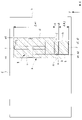
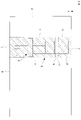
- the area setting unit 14 sets the boundary surface determined by the non-input item on the same side as the boundary surface with respect to the interference check area A. It is determined at the end of the setting area P which is located at and faces the boundary surface. 2 and 3 show an interference check area A when the setting values of all the setting items are input. 4 and 5 show an extended interference check area A when the set values of all non-essential items are not input.
- the boundary surfaces g and i are determined at the ends of the setting area P, so that the partial areas A2 and A3 surrounding the motor unit 9b become the setting area P. It is extended in the X direction to the end of.
- the boundary surfaces c, d, e, and f are determined at the end of the setting area P, so that the partial areas A2 and A3 surrounding the motor unit 9b are set. It is extended in the Y direction to the end of the region P.
- the area A1 surrounding the rotary table 9a is expanded in the Z direction by determining the boundary surface l as the mounting surface 4a which is the lower end of the setting area P.
- the interference check unit 15 checks whether the tool 2 and the interference check area A interfere with each other. For example, the interference check unit 15 assumes that the tool 2 and the table 4 have moved according to the control command before the control unit 13 transmits the control command to the feed motors 6, 7, and 8, and the tool 2 and the interference check area. The position of A is calculated, and it is checked whether or not the tool 2 and the interference check area A interfere with each other at the calculated position.
- the control unit 13 controls the feed motors 6, 7, and 8 to at least one of the spindle 3 and the table 4. Perform actions to avoid interference. For example, the control unit 13 stops the spindle 3 and the table 4, or moves the spindle 3 and the table 4 in a direction away from each other.
- the interference check area A is set as shown in FIG. 6 before the start of automatic or manual operation.
- the basic shape data used for the interference check area A is selected by the operator using the input unit 12 (step S1).
- a set value for determining a plurality of boundary surfaces of the interference check area A is input by the operator using the input unit 12 (step S2).
- step S3 After the input of the set value is completed (YES in step S3), it is confirmed by the area setting unit 14 that the set value of all the required items has been input (step S4). Completion of input of the set value is determined based on, for example, pressing a predetermined button on the setting screen by the operator. If there is a required item for which the set value has not been input, the control device 1 outputs an error (step S5) and requests the operator to input the set value of the required item that has not been input.
- the interference check area A of the auxiliary mechanism 9 is created and set by the area setting unit 14 based on the basic shape data selected in step S1 and the set value input in step S2 (step S6).
- the positions of all the boundary surfaces a, b, ..., M, n of the interference check area A are set as shown in FIGS. 2 and 3. Determined based on the value.
- the process proceeds to step S7 with the position of the boundary surface corresponding to the non-input item undetermined.
- the area setting unit 14 confirms whether or not the set values of all the non-essential items have been input (step S7).
- the set values of all the non-essential items are input (YES in step S7)
- the creation and setting of the interference check area A of the auxiliary mechanism 9 is completed.
- the interference check area A is set by determining the undetermined boundary surface at the end of the predetermined setting area P by the area setting unit 14. It is expanded to the end of the area P (step S8), and the creation and setting of the interference check area A of the auxiliary mechanism 9 is completed.
- the interference check unit 15 checks whether or not the tool 2 and the interference check area A interfere with each other.
- the interference check area A of the auxiliary mechanism 9 is created by a simple operation of giving a set value to a predetermined basic shape data registered in advance in the storage unit 11. Will be done. Therefore, the interference check area A of various auxiliary mechanisms 9 can be easily set in a short time.
- the boundary surface corresponding to the non-input item is automatically determined at the end of the setting area P, for example, the end of the operating range of the tool 2, and the end of the setting area P.
- the interference check area A extended to is automatically set. That is, the operator can omit the input of the set value of the non-essential item, and can set the interference check area A more easily and in a shorter time.
- the number of setting items for which input of setting values is indispensable can be reduced to nine.
- interference check area A By extending the interference check area A to the end of the operating range of the tool 2, interference between the tool 2 and the auxiliary mechanism 9 can be more reliably prevented and safety can be enhanced. Further, if the operator forgets to input the setting value of the non-essential item, the interference check area A can be automatically adjusted in the direction of enhancing the safety. Further, in the case of the additional two-axis table, normally, the tool 2 does not move to the outside of the rotary table 9a in the X direction and the Y direction during the machining of the work W. Therefore, the movement of the tool 2 is not unnecessarily restricted by extending the interference check area A to the end of the operating range of the tool 2.
- the interference check region A includes a plurality of partial regions A2 and A3 surrounding the stationary portion 9b, a plurality of boundary surfaces of the partial regions A2 and A3 exist on the same side of the interference check region A.
- the item that determines the position of the boundary surface other than the outermost boundary surface among the plurality of boundary surfaces on the same side may be a non-essential item.
- the smaller of ⁇ m and ⁇ n may be a non-essential item.
- the area setting unit 14 determines the set value of one of ⁇ m and ⁇ n to be the same as the set value of the other. As a result, the number of setting items that require input of setting values can be further reduced to eight.
- FIGS. 7 to 10 show an example of the interference check area A when the auxiliary mechanism 9 is a vise which is a kind of jig.
- the interference check area A of the vise consists of three partial areas surrounding each of the three stationary parts.
- 13 setting items 1 to 13 are provided.
- 7 and 8 show the interference check area A when the set values of all the setting items are input.
- 9 and 10 show an extended interference check area A when the set values of all non-essential items are not input.
- the setting items 1 and 2 are the Y coordinates ya and yb of the boundary surfaces a and b.
- the setting items 3 to 8 are the X coordinates xc, xd, xe, xf, xg, xh of the boundary surfaces c, d, e, f, g, h.
- the setting item 9 is the width ⁇ ai between the boundary surfaces a and i, and the setting item 10 is the width ⁇ bj between the boundary surfaces b and j.
- the setting items 11, 12, and 13 are Z coordinates zk, zl, zm of the boundary surfaces k, l, m.
- An example of a non-essential item is an item ⁇ ai, ⁇ bj for determining the positions of the boundary surfaces i and i facing outward of the interference check region A in the Y direction along the mounting surface 4a, respectively.
- Another example of the non-essential item is the position of two boundary surfaces e, g other than the outermost boundary surface c among the three boundary surfaces c, e, g located on the same side of the interference check area A.
- Items xe and xg for determining.
- Another example of the non-essential item is the position of two boundary surfaces f, h other than the outermost boundary surface d among the three boundary surfaces d, f, h located on the same side of the interference check area A.
- Items xf and xh for determining Another example of the non-essential item is to determine the position of one boundary surface m other than the outermost boundary surface l among the two boundary surfaces l and m located on the same side of the interference check area A. Item zm. In this example, there are 5 required items and 7 non-essential items. That is, the number of setting items that require the operator to input the setting value can be reduced from the conventional 13 to 5.
- the central partial region arranged between the boundary surfaces a and b corresponds to the portion that receives the lower surface of the work W.
- the operator may determine that this portion is unlikely to interfere with the tool 2 and may omit the middle partial region as shown in FIGS. 9 and 10. In this case, since the item zk does not exist, there are eight non-essential items.
- the area setting unit 14 may refer to the position information of the auxiliary mechanism 9 already stored in the storage unit 11 and automatically set the setting values of some setting items.
- the position information regarding the position of the auxiliary mechanism 9 may have already been input to and set in the control device 1.
- the area setting unit 14 automatically sets the set value of the item (Bx, By, Bz) based on the position and direction of the inclined axis B stored in the storage unit 11. As a result, the number of setting items that the operator must enter the setting value can be further reduced.
- Expanding the interference check area A works in the direction of improving safety.
- the control device 1 further includes the proposal unit 16 and there is a space in the setting area P where no object exists, the proposal unit 16 interferes so that this space is included in the interference check area A.
- An extension of the check area A may be proposed.
- an image of the setting area P is acquired by a visual sensor 17 such as a camera installed above the table 4.
- the proposal unit 16 determines whether or not an object exists between the auxiliary mechanism 9 and the end of the setting region P based on the image. When it is determined that the object does not exist, the proposal unit 16 proposes to the operator to change the boundary surface of the interference check area A to the end of the setting area P and expand the interference check area A.
- the proposal unit 16 determines whether or not an object exists in a gap of a predetermined width or less between the two partial regions based on the image, and if it is determined that the object does not exist, the two partial regions are expanded. You may suggest to the operator to combine with each other. Instead of the proposal unit 16 proposing the expansion of the interference check area A, the area setting unit 14 may automatically expand the interference check area A.
- the proposal unit 16 may propose the interference check area A having a simpler shape to the operator. For example, after the basic shape data is selected by the operator, the proposal unit 16 may propose to expand the interference check area A or combine a plurality of partial areas into one.
- the auxiliary mechanism 9 may be any device generally installed on the mounting surface 4a.
- the auxiliary mechanism 9 may be a contact-type tool length switch for measuring the tool length.
- a plurality of auxiliary mechanisms 9 may be installed on the mounting surface 4a, and in this case, a plurality of interference check areas A may be set.
- the spindle 3 is movable in the Z direction and the table 4 is movable in the X and Y directions, but the relative movement of the spindle 3 and the table 4 is the relative movement of the spindle 3 and the table 4. It may be achieved by moving either or both.
- the spindle 3 may be movable in the XY direction and the table 4 may be movable in the Z direction, or one of the spindle 3 and the table 4 may be movable in the three directions of X, Y, and Z. You may.
- the spindle 3 is arranged vertically and the table 4 is arranged horizontally, but the arrangement directions of the spindle 3 and the table 4 can be changed as appropriate.
- the spindle 3 may be arranged horizontally and the table 4 may be arranged vertically.
Landscapes
- Engineering & Computer Science (AREA)
- Human Computer Interaction (AREA)
- Manufacturing & Machinery (AREA)
- Physics & Mathematics (AREA)
- General Physics & Mathematics (AREA)
- Automation & Control Theory (AREA)
- Numerical Control (AREA)
Abstract
工作機械(10)の制御装置(1)は、3次元の基本形状データを記憶する記憶部(11)と、基本形状データからテーブル(4)上の補助機構(9)の干渉チェック領域を作成し、干渉チェック領域を補助機構(9)を囲む所定の設定領域内に設定する領域設定部(14)と、干渉チェック領域の複数の境界面の各々の位置を決定するための複数の設定項目の設定値が操作者によって入力される入力部(12)とを備え、複数の設定項目は、設定値の入力が必須でない少なくとも1つの非必須項目を含み、領域設定部(14)が、入力部(12)に入力された設定値に基づいて干渉チェック領域を設定し、設定値が入力されていない非必須項目である未入力項目が存在する場合、該未入力項目によって決定される境界面を所定の設定領域の端に設定する。
Description
本発明は、工作機械の制御装置に関するものである。
工作機械のテーブル上には、テーブルに対してワークを固定するための治具またはテーブルに対するワークの姿勢を変化させるための付加軸テーブル等の補助機構が設置される。工作機械の運転中の工具と補助機構との意図しない干渉を防止するために、工具と補助機構との干渉をチェックする機能を有する工作機械の制御装置が知られている(例えば、特許文献1および2参照。)。特許文献1,2において、補助機構および工具の3次元データを用いて補助機構および工具の各々の干渉領域を設定し、補助機構および工具の移動をシミュレーションし、干渉領域同士が干渉するか否かをチェックしている。
使用される補助機構の形状および寸法は、ユーザ毎に異なり得る。さらに、同一の補助機構であっても、設置方向および設置位置がユーザ毎に異なり得る。そのため、干渉領域の設定に時間がかかり不便である。
本開示の一態様は、工具とテーブル上の補助機構との干渉をチェックする機能を有する工作機械の制御装置であって、3次元の基本形状データを記憶する記憶部と、前記基本形状データから前記補助機構の干渉チェック領域を作成し、該干渉チェック領域を前記補助機構を囲む所定の設定領域内に設定する領域設定部と、前記干渉チェック領域の複数の境界面の各々の位置を決定するための複数の設定項目の設定値が操作者によって入力される入力部とを備え、前記複数の設定項目は、前記設定値の入力が必須でない少なくとも1つの非必須項目を含み、前記領域設定部が、前記入力部に入力された前記設定値に基づいて前記干渉チェック領域を設定し、前記設定値が入力されていない前記非必須項目である未入力項目が存在する場合、該未入力項目によって決定される前記境界面を前記所定の設定領域の端に設定する、工作機械の制御装置である。
以下に、一実施形態に係る工作機械10およびその制御装置1について図面を参照して説明する。
図1に示されるように、工作機械10は、工具2を保持する主軸3と、ワークWが載置されるテーブル4と、主軸3を回転させる主軸モータ5と、主軸3をテーブル4に対してZ方向に移動させるZ軸送りモータ6と、テーブル4を主軸3に対してX方向およびY方向にそれぞれに移動させるX軸送りモータ7およびY軸送りモータ8と、モータ5,6,7,8を制御する数値制御装置1とを備える。
図1に示されるように、工作機械10は、工具2を保持する主軸3と、ワークWが載置されるテーブル4と、主軸3を回転させる主軸モータ5と、主軸3をテーブル4に対してZ方向に移動させるZ軸送りモータ6と、テーブル4を主軸3に対してX方向およびY方向にそれぞれに移動させるX軸送りモータ7およびY軸送りモータ8と、モータ5,6,7,8を制御する数値制御装置1とを備える。
Z方向は、主軸3に保持された工具2の長手軸に沿う方向である。X方向およびY方向は、主軸3に保持された工具2の長手軸に直交する方向であり、相互に直交する。図1の工作機械10において、Z方向は鉛直方向であり、X方向およびY方向は水平方向である。
主軸3は、鉛直方向に配置され、図示しない支持機構によって鉛直方向に移動可能に支持されている。工具2は、主軸3の下端部に主軸3と同軸に保持され、主軸3と一体的に回転し移動する。
主軸3は、鉛直方向に配置され、図示しない支持機構によって鉛直方向に移動可能に支持されている。工具2は、主軸3の下端部に主軸3と同軸に保持され、主軸3と一体的に回転し移動する。
テーブル4は、主軸3の下方に水平に配置されている。テーブル4の上面である載置面4a上には、ワークWを保持する補助機構9が設置されている。補助機構9は、例えば、ワークWをテーブル4に対して固定する治具、または、テーブル4に対するワークWの姿勢を変更する付加軸テーブルである。
送りモータ6,7,8は、それぞれサーボモータである。送りモータ7,8は、テーブル4をX方向およびY方向に移動させることによって、テーブル4に対して工具2を所定の動作範囲内においてX方向およびY方向に移動させる。例えば、X方向の動作範囲はテーブル4のX方向の両端の間であり、Y方向の動作範囲はテーブル4のY方向の両端の間である。
制御装置1は、記憶部11と、入力部12と、制御部13とを備える。
記憶部11は、RAM、ROMおよびその他の任意の記憶装置を有する。
入力部12は、タッチパネル、マウスおよびキーボード等を有する。操作者は、入力部12を使用して制御装置1への様々な入力操作を行うことができる。
記憶部11は、RAM、ROMおよびその他の任意の記憶装置を有する。
入力部12は、タッチパネル、マウスおよびキーボード等を有する。操作者は、入力部12を使用して制御装置1への様々な入力操作を行うことができる。
自動運転時、制御部13は、記憶部11に記憶された加工プログラムに基づく制御指令をモータ5,6,7,8に送信することによって、主軸3およびテーブル4の動作を制御する。手動運転時、制御部13は、操作者による操作入力装置(図示略)への入力に基づく制御指令をモータ5,6,7,8に送信することによって、主軸3およびテーブル4の動作を制御する。制御部13は、制御装置1に内蔵された中央演算処理装置のような少なくとも1つのプロセッサによって実現される。
さらに、制御装置1は、工作機械10の自動または手動運転中に工具2と補助機構9との間の干渉をチェックする機能として、領域設定部14および干渉チェック部15を備える。領域設定部14および干渉チェック部15は、制御部13と同様に、プロセッサによって実現される。
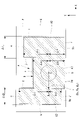
干渉をチェックするために、図2および図3に示されるように、所定の設定領域P内に補助機構9の干渉チェック領域Aが設定される。設定領域Pは、制御装置1に予め設定された補助機構9を囲む3次元領域であり、例えば工具2の動作範囲である。干渉チェック領域Aは、単一の領域または複数の部分領域A1,A2,A3の組み合わせから構成される。単一の領域および各部分領域A1,A2,A3は、直方体または円柱体のような単純な形状をそれぞれ有する。
図2および図3は、補助機構9がX方向に平行に設置された付加2軸テーブルである場合の干渉チェック領域Aの例を示している。付加2軸テーブル9は、回転テーブル9aおよび2つのモータユニット9bを有し、X方向に平行な傾斜軸線B回りおよび回転テーブル9aの中心軸線である回転軸線C回りに回転テーブル9aが回転可能である。
図2および図3は、補助機構9がX方向に平行に設置された付加2軸テーブルである場合の干渉チェック領域Aの例を示している。付加2軸テーブル9は、回転テーブル9aおよび2つのモータユニット9bを有し、X方向に平行な傾斜軸線B回りおよび回転テーブル9aの中心軸線である回転軸線C回りに回転テーブル9aが回転可能である。
記憶部11は、干渉チェック領域Aを作成するための複数の3次元の基本形状データを記憶している。複数の基本形状データは、相互に異なる形状であり、各基本形状データは、直方体または円柱体のような単純な形状の組合せによって構成される。
操作者は、干渉チェック領域Aに使用する基本形状データを入力部12で選択することができる。図2および図3の干渉チェック領域Aの場合、3つの部分領域A1,A2,A3に対応する3つの直方体から構成される基本形状データを選択する。
操作者は、干渉チェック領域Aに使用する基本形状データを入力部12で選択することができる。図2および図3の干渉チェック領域Aの場合、3つの部分領域A1,A2,A3に対応する3つの直方体から構成される基本形状データを選択する。
例えば、各基本形状データは、補助機構9の少なくとも1つの種類と関連付けられている。具体的には、3つの直方体から構成された基本形状データは、付加2軸テーブルと関連付けられている。操作者は、制御装置1の設定画面に表示された補助機構9の種類の一覧の中から、使用する補助機構9を選択する。補助機構9が選択されると、選択された補助機構9と関連付けられている少なくとも1つの基本形状データが設定画面に表示される。操作者は、入力部12を使用して、表示されている基本形状データの中から1つを選択する。
干渉チェック領域Aを定義するためには、干渉チェック領域Aを画定する複数の境界面の各々の位置を決定する必要がある。操作者は、複数の境界面の位置を決定するための複数の設定項目の設定値を入力部12に入力することができる。図2および図3の例の場合、干渉チェック領域Aは19個の境界面a,b,・・・,m,nによって画定され、境界面a,b,・・・,m,nの位置を決定するために16個の設定項目1~16が設けられている。
設定項目1~3は、回転テーブル9aの一方の側面における傾斜軸線Bの位置のXYZ座標(Bx,By,Bz)である。
設定項目4は、回転テーブル9aの他方の側面のX座標xjである。
設定項目5,6,7,8,9,10,11,12は、傾斜軸線(所定の軸線)Bから傾斜軸線Bに平行な境界面a,b,c,d,e,f,k,lまでの距離Δa,Δb,Δc,Δd,Δe,Δf,Δk,Δlである。
設定項目13は、境界面h,g間の幅Δghであり、設定項目14は境界面i,j間の幅Δijである。
設定項目15,16は、載置面4aから境界面m,nまでの距離Δm,Δnである。
設定項目4は、回転テーブル9aの他方の側面のX座標xjである。
設定項目5,6,7,8,9,10,11,12は、傾斜軸線(所定の軸線)Bから傾斜軸線Bに平行な境界面a,b,c,d,e,f,k,lまでの距離Δa,Δb,Δc,Δd,Δe,Δf,Δk,Δlである。
設定項目13は、境界面h,g間の幅Δghであり、設定項目14は境界面i,j間の幅Δijである。
設定項目15,16は、載置面4aから境界面m,nまでの距離Δm,Δnである。
例えば、入力部12は、数字キーパッドを有する操作盤であり、操作者は、数字キーパッドを使用して入力部12に設定値を入力する。入力部12がタッチパネルを有する場合、操作者は、タッチパネルに表示された基本形状データの各境界面の位置を、使用する補助機構9の形状および寸法に応じた位置へタッチ操作によって移動させることで、各設定値を入力してもよい。入力部12がマイク等の音声入力装置を有する場合、操作者の音声として設定値が入力されてもよい。
複数の設定項目は、操作者による設定値の入力が必須である必須項目と、操作者による設定値の入力が必須でない少なくとも1つの非必須項目とからなる。
非必須項目の一例は、載置面4aに沿うX方向およびY方向において干渉チェック領域Aの外方を向く境界面の内、補助機構9の静止部分9bを囲む部分領域A2,A3の境界面c,d,e,f,g,iの位置をそれぞれ決定するための項目Δc、Δd、Δe、Δf、Δgh,Δijである。静止部分9bは、テーブル4に対して静止した部分であり、付加2軸テーブルの場合、補助機構9の回転軸線C回りの回転に同期しない部分である。
非必須項目の他の例は、補助機構9の可動部分9aを囲む部分領域A1のテーブル4側の境界面lの位置を決定するための項目Δlである。可動部分9aは、テーブル4に対して可動の部分であり、付加2軸テーブルの場合、補助機構9の回転軸線C回りの回転に同期する部分である。
非必須項目の一例は、載置面4aに沿うX方向およびY方向において干渉チェック領域Aの外方を向く境界面の内、補助機構9の静止部分9bを囲む部分領域A2,A3の境界面c,d,e,f,g,iの位置をそれぞれ決定するための項目Δc、Δd、Δe、Δf、Δgh,Δijである。静止部分9bは、テーブル4に対して静止した部分であり、付加2軸テーブルの場合、補助機構9の回転軸線C回りの回転に同期しない部分である。
非必須項目の他の例は、補助機構9の可動部分9aを囲む部分領域A1のテーブル4側の境界面lの位置を決定するための項目Δlである。可動部分9aは、テーブル4に対して可動の部分であり、付加2軸テーブルの場合、補助機構9の回転軸線C回りの回転に同期する部分である。
領域設定部14は、入力部12で選択された形状の基本形状データを記憶部11から取得する。続いて、領域設定部14は、入力部12で選択された基本形状データと設定項目の設定値とに基づいて、干渉チェック領域Aを作成し干渉チェック領域Aを設定領域P内に設定する。つまり、領域設定部14は、基本形状データをX、Y、Z方向に拡大または縮小させ基本形状データの各境界面を設定値によって決定される位置に配置することによって、干渉チェック領域Aを作成する。
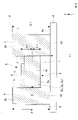
このように、領域設定部14は、入力部12に入力された必須項目および非必須項目の設定値に基づいて、各境界面の位置を決定する。設定値が入力されていない非必須項目である未入力項目が存在する場合、領域設定部14は、未入力項目によって決定される境界面を、干渉チェック領域Aに対して当該境界面と同一側に位置し当該境界面と対向する設定領域Pの端に決定する。図2および図3は、全ての設定項目の設定値が入力された場合の干渉チェック領域Aを示す。図4および図5は、全ての非必須項目の設定値が入力されなかった場合の拡張された干渉チェック領域Aを示す。
具体的には、項目Δgh,Δijが未入力項目である場合、境界面g,iが設定領域Pの端に決定されることによって、モータユニット9bを囲む部分領域A2,A3が、設定領域Pの端までX方向に拡張される。
項目Δc,Δd,Δe,Δfが未入力項目である場合、境界面c,d,e,fが設定領域Pの端に決定されることによって、モータユニット9bを囲む部分領域A2,A3が設定領域Pの端までY方向に拡張される。
項目Δlが未入力項目である場合、境界面lが設定領域Pの下側の端である載置面4aに決定されることによって、回転テーブル9aを囲む領域A1がZ方向に拡張される。
項目Δc,Δd,Δe,Δfが未入力項目である場合、境界面c,d,e,fが設定領域Pの端に決定されることによって、モータユニット9bを囲む部分領域A2,A3が設定領域Pの端までY方向に拡張される。
項目Δlが未入力項目である場合、境界面lが設定領域Pの下側の端である載置面4aに決定されることによって、回転テーブル9aを囲む領域A1がZ方向に拡張される。
干渉チェック部15は、工具2と干渉チェック領域Aとが相互に干渉するか否かをチェックする。例えば、干渉チェック部15は、制御部13が送りモータ6,7,8に制御指令を送信する前に、制御指令に従って工具2およびテーブル4が移動したと仮定したときの工具2および干渉チェック領域Aの位置を計算し、算出された位置において工具2と干渉チェック領域Aとが相互に干渉するか否かをチェックする。
工具2と干渉チェック領域Aとが相互に干渉すると干渉チェック部15によって判断された場合、制御部13は、送りモータ6,7,8を制御することによって、主軸3およびテーブル4の少なくとも一方に干渉を回避する動作を実行させる。例えば、制御部13は、主軸3およびテーブル4を停止させるか、または、主軸3およびテーブル4を相互に離間する方向に移動させる。
次に、工作機械10の制御装置1の作用について説明する。
テーブル4の載置面4a上に補助機構9を設置後、自動または手動運転の開始前に、図6に示されるように、干渉チェック領域Aが設定される。
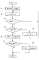
まず、干渉チェック領域Aに使用する基本形状データが、入力部12を使用して操作者によって選択される(ステップS1)。次に、干渉チェック領域Aの複数の境界面を決定するための設定値が、入力部12を使用して操作者によって入力される(ステップS2)。
テーブル4の載置面4a上に補助機構9を設置後、自動または手動運転の開始前に、図6に示されるように、干渉チェック領域Aが設定される。
まず、干渉チェック領域Aに使用する基本形状データが、入力部12を使用して操作者によって選択される(ステップS1)。次に、干渉チェック領域Aの複数の境界面を決定するための設定値が、入力部12を使用して操作者によって入力される(ステップS2)。
設定値の入力が完了した後(ステップS3のYES)、全ての必須項目の設定値が入力されたことが領域設定部14によって確認される(ステップS4)。設定値の入力の完了は、例えば、操作者による設定画面上の所定のボタンの押下に基づいて判断される。設定値が入力されていない必須項目が存在する場合、制御装置1は、エラーを出力し(ステップS5)、未入力の必須項目の設定値の入力を操作者に要求する。
次に、ステップS1において選択された基本形状データおよびステップS2において入力された設定値に基づき、領域設定部14によって補助機構9の干渉チェック領域Aが作成され設定される(ステップS6)。
全ての非必須項目に設定値が入力されている場合、図2および図3に示されるように、干渉チェック領域Aの全ての境界面a,b,・・・,m,nの位置が設定値に基づいて決定される。一方、少なくとも1つの非必須項目に設定値が入力されていない場合、未入力項目に対応する境界面の位置が未決定のまま、ステップS7に進む。
全ての非必須項目に設定値が入力されている場合、図2および図3に示されるように、干渉チェック領域Aの全ての境界面a,b,・・・,m,nの位置が設定値に基づいて決定される。一方、少なくとも1つの非必須項目に設定値が入力されていない場合、未入力項目に対応する境界面の位置が未決定のまま、ステップS7に進む。
次に、領域設定部14によって、全ての非必須項目の設定値が入力されたか否かが確認される(ステップS7)。全ての非必須項目の設定値が入力されている場合(ステップS7のYES)、補助機構9の干渉チェック領域Aの作成および設定が終了する。
一方、少なくとも1つの未入力項目が存在する場合(ステップS7のNO)、領域設定部14によって、未決定の境界面が所定の設定領域Pの端に決定されることによって干渉チェック領域Aが設定領域Pの端まで拡張され(ステップS8)、補助機構9の干渉チェック領域Aの作成および設定が終了する。
干渉チェック領域Aの設定終了後、工具2と干渉チェック領域Aとが干渉するか否かが干渉チェック部15によってチェックされる。
一方、少なくとも1つの未入力項目が存在する場合(ステップS7のNO)、領域設定部14によって、未決定の境界面が所定の設定領域Pの端に決定されることによって干渉チェック領域Aが設定領域Pの端まで拡張され(ステップS8)、補助機構9の干渉チェック領域Aの作成および設定が終了する。
干渉チェック領域Aの設定終了後、工具2と干渉チェック領域Aとが干渉するか否かが干渉チェック部15によってチェックされる。
このように、本実施形態によれば、記憶部11内に予め登録されている所定の基本形状データに対して設定値を与えるだけの簡単な作業によって、補助機構9の干渉チェック領域Aが作成される。したがって、様々な補助機構9の干渉チェック領域Aを容易に短時間で設定することができる。
また、非必須項目の設定値が入力されなかった場合、未入力項目に対応する境界面が設定領域Pの端、例えば工具2の動作範囲の端に自動的に決定され、設定領域Pの端まで拡張された干渉チェック領域Aが自動的に設定される。すなわち、操作者は、非必須項目の設定値の入力を省略することができ、干渉チェック領域Aをさらに容易に、かつ、さらに短時間で設定することができる。例えば、図2から図5の例の場合、従来、16個の設定項目の設定値の入力が要求されていた。本実施形態によれば、設定値の入力が必須である設定項目の数を9個まで減らすことができる。
また、干渉チェック領域Aを工具2の動作範囲の端まで拡張することによって、工具2と補助機構9との間の干渉をより確実に防止し、安全性を高めることができる。
また、操作者が非必須項目の設定値の入力を忘れた場合、安全性を高める方向に干渉チェック領域Aを自動的に調整することができる。
また、付加2軸テーブルの場合、通常、ワークWの加工中に工具2がX方向およびY方向において回転テーブル9aの外側まで移動することはない。したがって、干渉チェック領域Aを工具2の動作範囲の端まで拡張することにより工具2の移動が不要に制限されることはない。
また、操作者が非必須項目の設定値の入力を忘れた場合、安全性を高める方向に干渉チェック領域Aを自動的に調整することができる。
また、付加2軸テーブルの場合、通常、ワークWの加工中に工具2がX方向およびY方向において回転テーブル9aの外側まで移動することはない。したがって、干渉チェック領域Aを工具2の動作範囲の端まで拡張することにより工具2の移動が不要に制限されることはない。
干渉チェック領域Aが静止部分9bをそれぞれ囲む複数の部分領域A2,A3を含む場合、干渉チェック領域Aの同一側に部分領域A2,A3の複数の境界面が存在する。本実施形態において、同一側の複数の境界面の内、最も外側の境界面以外の境界面の位置を決定する項目が、非必須項目であってもよい。例えば、図2から図5の例において、ΔmおよびΔnの内、小さい方が非必須項目であってもよい。ΔmおよびΔnの一方が未入力項目である場合、領域設定部14は、ΔmおよびΔnの一方の設定値を他方の設定値と同一の値に決定する。
これにより、設定値の入力が必須である設定項目の数をさらに8個まで減らすことができる。
これにより、設定値の入力が必須である設定項目の数をさらに8個まで減らすことができる。
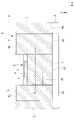
図7から図10は、補助機構9が治具の一種であるバイスである場合の干渉チェック領域Aの例を示している。バイスの干渉チェック領域Aは、3つの静止部分をそれぞれ囲む3つの部分領域からなる。図7から図10の例において、13個の設定項目1~13が設けられている。図7および図8は、全ての設定項目の設定値が入力された場合の干渉チェック領域Aを示す。図9および図10は、全ての非必須項目の設定値が入力されなかった場合の拡張された干渉チェック領域Aを示す。
設定項目1,2は、境界面a,bのY座標ya,ybである。設定項目3~8は、境界面c,d,e,f,g,hのX座標xc,xd,xe,xf,xg,xhである。設定項目9は、境界面a,i間の幅Δaiであり、設定項目10は、境界面b,j間の幅Δbjである。設定項目11,12,13は、境界面k,l,mのZ座標zk,zl,zmである。
非必須項目の一例は、載置面4aに沿うY方向において干渉チェック領域Aの外方を向く境界面i,iの位置をそれぞれ決定するための項目Δai、Δbjである。
非必須項目の他の例は、干渉チェック領域Aの同一側に位置する3つの境界面c,e,gの内、最も外側に位置する境界面c以外の2つの境界面e,gの位置を決定するための項目xe,xgである。
非必須項目の他の例は、干渉チェック領域Aの同一側に位置する3つの境界面d,f,hの内、最も外側に位置する境界面d以外の2つの境界面f,hの位置を決定するための項目xf,xhである。
非必須項目の他の例は、干渉チェック領域Aの同一側に位置する2つの境界面l,mの内、最も外側に位置する境界面l以外の1つの境界面mの位置を決定するための項目zmである。
この例において、必須項目は5個であり、非必須項目は7個である。すなわち、操作者による設定値の入力が必須である設定項目の数を従来の13個から5個まで減らすことができる。
非必須項目の他の例は、干渉チェック領域Aの同一側に位置する3つの境界面c,e,gの内、最も外側に位置する境界面c以外の2つの境界面e,gの位置を決定するための項目xe,xgである。
非必須項目の他の例は、干渉チェック領域Aの同一側に位置する3つの境界面d,f,hの内、最も外側に位置する境界面d以外の2つの境界面f,hの位置を決定するための項目xf,xhである。
非必須項目の他の例は、干渉チェック領域Aの同一側に位置する2つの境界面l,mの内、最も外側に位置する境界面l以外の1つの境界面mの位置を決定するための項目zmである。
この例において、必須項目は5個であり、非必須項目は7個である。すなわち、操作者による設定値の入力が必須である設定項目の数を従来の13個から5個まで減らすことができる。
干渉チェック領域Aの作成に使用される基本形状データが複雑であり境界面の数が多い程、干渉チェック領域Aを作成するための演算量が増加し制御装置1の負荷が増大する。演算量を低減するために、工具2との干渉が少ない補助機構9の一部分には干渉チェック領域Aを設定しなくてもよい。
例えば、図7および図8において、境界面a,b間に配置される真ん中の部分領域は、ワークWの下面を受ける部分に対応する。操作者は、この部分は工具2と干渉する可能性が低いと判断し、図9および図10に示されるように、真ん中の部分領域を省略してもよい。この場合、項目zkが存在しないので、非必須項目は8個である。
例えば、図7および図8において、境界面a,b間に配置される真ん中の部分領域は、ワークWの下面を受ける部分に対応する。操作者は、この部分は工具2と干渉する可能性が低いと判断し、図9および図10に示されるように、真ん中の部分領域を省略してもよい。この場合、項目zkが存在しないので、非必須項目は8個である。
本実施形態において、領域設定部14が、記憶部11に既に記憶されている補助機構9の位置情報を参照し、一部の設定項目の設定値を自動的に設定してもよい。
干渉チェック領域Aの設定を行う前に、補助機構9の位置に関する位置情報が既に制御装置1に入力され設定されていることがある。例えば、付加2軸テーブルの場合、傾斜軸線Bの位置および方向が、干渉チェック領域Aの設定よりも先に記憶部11に記憶される。この場合、領域設定部14が、記憶部11に記憶されている傾斜軸線Bの位置および方向に基づいて項目(Bx,By,Bz)の設定値を自動的に設定する。これにより、操作者が設定値を入力しなければならない設定項目の数をさらに減らすことができる。
干渉チェック領域Aの設定を行う前に、補助機構9の位置に関する位置情報が既に制御装置1に入力され設定されていることがある。例えば、付加2軸テーブルの場合、傾斜軸線Bの位置および方向が、干渉チェック領域Aの設定よりも先に記憶部11に記憶される。この場合、領域設定部14が、記憶部11に記憶されている傾斜軸線Bの位置および方向に基づいて項目(Bx,By,Bz)の設定値を自動的に設定する。これにより、操作者が設定値を入力しなければならない設定項目の数をさらに減らすことができる。
干渉チェック領域Aを拡張することは、安全性を高める方向に働く。本実施形態においては、制御装置1が提案部16をさらに備え、設定領域P内に物体が存在しない空間が存在する場合、提案部16が、この空間が干渉チェック領域Aに含まれるように干渉チェック領域Aの拡張を提案してもよい。
例えば、テーブル4の上方に設置されたカメラのような視覚センサ17によって設定領域Pの画像が取得される。提案部16は、補助機構9と設定領域Pの端との間に物体が存在するか否かを画像に基づいて判定する。物体が存在しないと判定された場合、提案部16は、干渉チェック領域Aの境界面を設定領域Pの端に変更し干渉チェック領域Aを拡張することを操作者に提案する。
提案部16は、2つの部分領域間の所定の幅以下の隙間に物体が存在するか否かを画像に基づいて判定し、物体が存在しないと判定された場合、2つの部分領域を拡張し相互に結合することを操作者に提案してもよい。
提案部16が干渉チェック領域Aの拡張を提案することに代えて、領域設定部14が、干渉チェック領域Aを自動的に拡張してもよい。
提案部16は、2つの部分領域間の所定の幅以下の隙間に物体が存在するか否かを画像に基づいて判定し、物体が存在しないと判定された場合、2つの部分領域を拡張し相互に結合することを操作者に提案してもよい。
提案部16が干渉チェック領域Aの拡張を提案することに代えて、領域設定部14が、干渉チェック領域Aを自動的に拡張してもよい。
干渉チェック領域Aの設定に要する演算量を減らし制御装置1の負荷を減らすために、提案部16が、より簡易な形状の干渉チェック領域Aを操作者に提案してもよい。例えば、基本形状データが操作者によって選択された後、提案部16が、干渉チェック領域Aを拡張したり、複数の部分領域を1つに結合したりすることを提案してもよい。
本実施形態において、補助機構9が付加軸テーブルおよび治具である場合について説明したが、補助機構9は、一般に載置面4a上に設置される任意のデバイスであってもよい。例えば、補助機構9は、工具長を測定するための接触式の工具長スイッチであってもよい。また、載置面4a上に複数の補助機構9が設置されてもよく、この場合には複数の干渉チェック領域Aが設定されてもよい。
本実施形態において、主軸3がZ方向に移動可能であり、テーブル4がX方向およびY方向に移動可能であることとしたが、主軸3およびテーブル4の相対移動は、主軸3およびテーブル4のいずれか一方または両方の移動によって達成されればよい。例えば、主軸3がXY方向に移動可能であり、テーブル4がZ方向に移動可能であってもよく、または、主軸3およびテーブル4の一方がX、Y、Zの3方向に移動可能であってもよい。
また、本実施形態において、主軸3が鉛直に配置され、テーブル4が水平に配置されることとしたが、主軸3およびテーブル4の配置方向は、適宜変更可能である。例えば、主軸3が水平に配置され、テーブル4が鉛直に配置されてもよい。
また、本実施形態において、主軸3が鉛直に配置され、テーブル4が水平に配置されることとしたが、主軸3およびテーブル4の配置方向は、適宜変更可能である。例えば、主軸3が水平に配置され、テーブル4が鉛直に配置されてもよい。
1 数値制御装置(制御装置)
2 工具
4 テーブル
9 補助機構
10 工作機械
11 記憶部
12 入力部
14 領域設定部
16 提案部
a,b,c,d,e,f,g,f,i,j,k,l,m,n 境界面
A 干渉チェック領域
B 傾斜軸線(所定の軸線)
P 設定領域
2 工具
4 テーブル
9 補助機構
10 工作機械
11 記憶部
12 入力部
14 領域設定部
16 提案部
a,b,c,d,e,f,g,f,i,j,k,l,m,n 境界面
A 干渉チェック領域
B 傾斜軸線(所定の軸線)
P 設定領域
Claims (4)
- 工具とテーブル上の補助機構との干渉をチェックする機能を有する工作機械の制御装置であって、
3次元の基本形状データを記憶する記憶部と、
前記基本形状データから前記補助機構の干渉チェック領域を作成し、該干渉チェック領域を前記補助機構を囲む所定の設定領域内に設定する領域設定部と、
前記干渉チェック領域の複数の境界面の各々の位置を決定するための複数の設定項目の設定値が操作者によって入力される入力部とを備え、
前記複数の設定項目は、前記設定値の入力が必須でない少なくとも1つの非必須項目を含み、
前記領域設定部が、
前記入力部に入力された前記設定値に基づいて前記干渉チェック領域を設定し、
前記設定値が入力されていない前記非必須項目である未入力項目が存在する場合、該未入力項目によって決定される前記境界面を前記所定の設定領域の端に設定する、工作機械の制御装置。 - 前記所定の設定領域が、前記工具の動作範囲である、請求項1に記載の工作機械の制御装置。
- 前記非必須項目が、前記干渉チェック領域の外方を向く前記境界面の内、前記補助機構の静止部分を囲む境界面の位置を決定するための項目である、請求項1または請求項2に記載の工作機械の制御装置。
- 前記非必須項目が、前記干渉チェック領域の同一側に位置する2以上の境界面の内、最も外側に位置する境界面以外の境界面の位置を決定するための項目である、請求項1から請求項3のいずれかに記載の工作機械の制御装置。
Priority Applications (4)
| Application Number | Priority Date | Filing Date | Title |
|---|---|---|---|
| US18/043,110 US20230305515A1 (en) | 2020-09-25 | 2021-09-21 | Machine tool controller |
| CN202180064635.6A CN116261694A (zh) | 2020-09-25 | 2021-09-21 | 机床的控制装置 |
| DE112021003859.1T DE112021003859T5 (de) | 2020-09-25 | 2021-09-21 | Steuerung für eine werkzeugmaschine |
| JP2022551981A JP7469493B2 (ja) | 2020-09-25 | 2021-09-21 | 工作機械の制御装置 |
Applications Claiming Priority (2)
| Application Number | Priority Date | Filing Date | Title |
|---|---|---|---|
| JP2020-160887 | 2020-09-25 | ||
| JP2020160887 | 2020-09-25 |
Publications (1)
| Publication Number | Publication Date |
|---|---|
| WO2022065280A1 true WO2022065280A1 (ja) | 2022-03-31 |
Family
ID=80846643
Family Applications (1)
| Application Number | Title | Priority Date | Filing Date |
|---|---|---|---|
| PCT/JP2021/034514 Ceased WO2022065280A1 (ja) | 2020-09-25 | 2021-09-21 | 工作機械の制御装置 |
Country Status (5)
| Country | Link |
|---|---|
| US (1) | US20230305515A1 (ja) |
| JP (1) | JP7469493B2 (ja) |
| CN (1) | CN116261694A (ja) |
| DE (1) | DE112021003859T5 (ja) |
| WO (1) | WO2022065280A1 (ja) |
Citations (2)
| Publication number | Priority date | Publication date | Assignee | Title |
|---|---|---|---|---|
| JPH03131908A (ja) * | 1989-10-18 | 1991-06-05 | Mitsubishi Electric Corp | 数値制御の干渉チエツク方式 |
| JP2008015740A (ja) * | 2006-07-05 | 2008-01-24 | Mori Seiki Co Ltd | 工作機械の制御装置 |
Family Cites Families (10)
| Publication number | Priority date | Publication date | Assignee | Title |
|---|---|---|---|---|
| JPH08115117A (ja) | 1994-10-18 | 1996-05-07 | Imao Corp:Kk | 加工シミュレーションによる干渉チェック方法 |
| JP4578742B2 (ja) * | 2001-09-27 | 2010-11-10 | 株式会社森精機製作所 | 干渉防止装置 |
| JP2003103484A (ja) * | 2001-09-28 | 2003-04-08 | Honda Motor Co Ltd | ロボットのインターロック設定方法 |
| JP2005081445A (ja) * | 2003-09-04 | 2005-03-31 | Fanuc Ltd | ロボットの干渉領域確認装置 |
| JP4456455B2 (ja) | 2004-10-08 | 2010-04-28 | 中村留精密工業株式会社 | 旋盤における機械稼働部の衝突防止方法 |
| JP2007249671A (ja) * | 2006-03-16 | 2007-09-27 | Nakamura Tome Precision Ind Co Ltd | 工作機械の衝突防止方法 |
| JP4298770B2 (ja) * | 2007-08-28 | 2009-07-22 | ファナック株式会社 | 干渉チェック機能を備えた数値制御装置 |
| JP2010067101A (ja) * | 2008-09-12 | 2010-03-25 | Toshiba Mach Co Ltd | 工具の干渉域設定方法 |
| JP6209392B2 (ja) * | 2013-08-12 | 2017-10-04 | Dmg森精機株式会社 | 干渉確認装置 |
| KR20200035654A (ko) * | 2018-09-27 | 2020-04-06 | 현대위아 주식회사 | 공작기계 z축 충돌방지 자동설정 방법 |
-
2021
- 2021-09-21 JP JP2022551981A patent/JP7469493B2/ja active Active
- 2021-09-21 WO PCT/JP2021/034514 patent/WO2022065280A1/ja not_active Ceased
- 2021-09-21 CN CN202180064635.6A patent/CN116261694A/zh active Pending
- 2021-09-21 DE DE112021003859.1T patent/DE112021003859T5/de active Pending
- 2021-09-21 US US18/043,110 patent/US20230305515A1/en not_active Abandoned
Patent Citations (2)
| Publication number | Priority date | Publication date | Assignee | Title |
|---|---|---|---|---|
| JPH03131908A (ja) * | 1989-10-18 | 1991-06-05 | Mitsubishi Electric Corp | 数値制御の干渉チエツク方式 |
| JP2008015740A (ja) * | 2006-07-05 | 2008-01-24 | Mori Seiki Co Ltd | 工作機械の制御装置 |
Also Published As
| Publication number | Publication date |
|---|---|
| JP7469493B2 (ja) | 2024-04-16 |
| US20230305515A1 (en) | 2023-09-28 |
| JPWO2022065280A1 (ja) | 2022-03-31 |
| CN116261694A (zh) | 2023-06-13 |
| DE112021003859T5 (de) | 2023-05-04 |
Similar Documents
| Publication | Publication Date | Title |
|---|---|---|
| EP1195665B1 (en) | Apparatus and method for setting control parameters of machining apparatus | |
| JP5554235B2 (ja) | 干渉チェック装置及び干渉チェック方法並びに干渉チェック装置を備えた工作機械 | |
| US9897991B2 (en) | Machine tool | |
| TWI515077B (zh) | 具有自動安全再定位之機械加工系統控制 | |
| JP2009266221A (ja) | 加工シミュレーション方法及び加工シミュレーション装置 | |
| JP5079165B2 (ja) | 数値制御装置及び数値制御方法 | |
| JP2016101644A (ja) | 加工動作をロボットに教示するロボットプログラミング装置 | |
| JP7473321B2 (ja) | シミュレーション装置、数値制御装置、及びシミュレーション方法 | |
| JPWO2011132221A1 (ja) | 数値制御方法及びその装置 | |
| JP7087894B2 (ja) | 制御装置、工作機械、制御方法及びコンピュータプログラム | |
| JP2019104097A (ja) | ロボットシステム | |
| JP7469493B2 (ja) | 工作機械の制御装置 | |
| JP2006195862A (ja) | 数値制御装置及び数値制御方法 | |
| US10133253B2 (en) | Operation limiting device for machine tool | |
| JP2010067101A (ja) | 工具の干渉域設定方法 | |
| JP2022132984A (ja) | プログラム、clデータ編集装置及び工作機械 | |
| KR102012627B1 (ko) | 프로그램 생성 장치 | |
| JPH07136855A (ja) | ワイヤ放電加工装置 | |
| JP5382419B2 (ja) | 原点サーチ支援装置及びプログラム | |
| JP2021077074A (ja) | 数値制御装置と数値制御装置の制御方法 | |
| JP7659073B2 (ja) | 評価用プログラム作成装置、及びプログラムを記録したコンピュータ読み取り可能な記録媒体 | |
| JP6915182B1 (ja) | 工作機械、工作機械の制御方法、および工作機械の制御プログラム | |
| JP7735900B2 (ja) | 制御装置、工作機械、制御方法及びコンピュータプログラム | |
| JP2014164713A (ja) | 制御装置、工作機械、及び制御方法 | |
| JP6620460B2 (ja) | 工作機械、工作機械の主軸の位置補正方法及びコンピュータプログラム |
Legal Events
| Date | Code | Title | Description |
|---|---|---|---|
| 121 | Ep: the epo has been informed by wipo that ep was designated in this application |
Ref document number: 21872409 Country of ref document: EP Kind code of ref document: A1 |
|
| ENP | Entry into the national phase |
Ref document number: 2022551981 Country of ref document: JP Kind code of ref document: A |
|
| 122 | Ep: pct application non-entry in european phase |
Ref document number: 21872409 Country of ref document: EP Kind code of ref document: A1 |