WO2022065179A1 - 繊維強化樹脂管体の製造方法 - Google Patents
繊維強化樹脂管体の製造方法 Download PDFInfo
- Publication number
- WO2022065179A1 WO2022065179A1 PCT/JP2021/034043 JP2021034043W WO2022065179A1 WO 2022065179 A1 WO2022065179 A1 WO 2022065179A1 JP 2021034043 W JP2021034043 W JP 2021034043W WO 2022065179 A1 WO2022065179 A1 WO 2022065179A1
- Authority
- WO
- WIPO (PCT)
- Prior art keywords
- mold
- fiber
- metal member
- inflow
- resin
- Prior art date
- Legal status (The legal status is an assumption and is not a legal conclusion. Google has not performed a legal analysis and makes no representation as to the accuracy of the status listed.)
- Ceased
Links
Images




Classifications
-
- B—PERFORMING OPERATIONS; TRANSPORTING
- B29—WORKING OF PLASTICS; WORKING OF SUBSTANCES IN A PLASTIC STATE IN GENERAL
- B29C—SHAPING OR JOINING OF PLASTICS; SHAPING OF MATERIAL IN A PLASTIC STATE, NOT OTHERWISE PROVIDED FOR; AFTER-TREATMENT OF THE SHAPED PRODUCTS, e.g. REPAIRING
- B29C70/00—Shaping composites, i.e. plastics material comprising reinforcements, fillers or preformed parts, e.g. inserts
- B29C70/04—Shaping composites, i.e. plastics material comprising reinforcements, fillers or preformed parts, e.g. inserts comprising reinforcements only, e.g. self-reinforcing plastics
- B29C70/28—Shaping operations therefor
- B29C70/40—Shaping or impregnating by compression not applied
- B29C70/42—Shaping or impregnating by compression not applied for producing articles of definite length, i.e. discrete articles
- B29C70/46—Shaping or impregnating by compression not applied for producing articles of definite length, i.e. discrete articles using matched moulds, e.g. for deforming sheet moulding compounds [SMC] or prepregs
- B29C70/48—Shaping or impregnating by compression not applied for producing articles of definite length, i.e. discrete articles using matched moulds, e.g. for deforming sheet moulding compounds [SMC] or prepregs and impregnating the reinforcements in the closed mould, e.g. resin transfer moulding [RTM], e.g. by vacuum
-
- B—PERFORMING OPERATIONS; TRANSPORTING
- B29—WORKING OF PLASTICS; WORKING OF SUBSTANCES IN A PLASTIC STATE IN GENERAL
- B29C—SHAPING OR JOINING OF PLASTICS; SHAPING OF MATERIAL IN A PLASTIC STATE, NOT OTHERWISE PROVIDED FOR; AFTER-TREATMENT OF THE SHAPED PRODUCTS, e.g. REPAIRING
- B29C43/00—Compression moulding, i.e. applying external pressure to flow the moulding material; Apparatus therefor
- B29C43/02—Compression moulding, i.e. applying external pressure to flow the moulding material; Apparatus therefor of articles of definite length, i.e. discrete articles
- B29C43/10—Isostatic pressing, i.e. using non-rigid pressure-exerting members against rigid parts or dies
-
- B—PERFORMING OPERATIONS; TRANSPORTING
- B29—WORKING OF PLASTICS; WORKING OF SUBSTANCES IN A PLASTIC STATE IN GENERAL
- B29C—SHAPING OR JOINING OF PLASTICS; SHAPING OF MATERIAL IN A PLASTIC STATE, NOT OTHERWISE PROVIDED FOR; AFTER-TREATMENT OF THE SHAPED PRODUCTS, e.g. REPAIRING
- B29C43/00—Compression moulding, i.e. applying external pressure to flow the moulding material; Apparatus therefor
- B29C43/32—Component parts, details or accessories; Auxiliary operations
- B29C43/34—Feeding the material to the mould or the compression means
-
- B—PERFORMING OPERATIONS; TRANSPORTING
- B29—WORKING OF PLASTICS; WORKING OF SUBSTANCES IN A PLASTIC STATE IN GENERAL
- B29C—SHAPING OR JOINING OF PLASTICS; SHAPING OF MATERIAL IN A PLASTIC STATE, NOT OTHERWISE PROVIDED FOR; AFTER-TREATMENT OF THE SHAPED PRODUCTS, e.g. REPAIRING
- B29C43/00—Compression moulding, i.e. applying external pressure to flow the moulding material; Apparatus therefor
- B29C43/32—Component parts, details or accessories; Auxiliary operations
- B29C43/36—Moulds for making articles of definite length, i.e. discrete articles
- B29C43/3642—Bags, bleeder sheets or cauls for isostatic pressing
-
- B—PERFORMING OPERATIONS; TRANSPORTING
- B29—WORKING OF PLASTICS; WORKING OF SUBSTANCES IN A PLASTIC STATE IN GENERAL
- B29C—SHAPING OR JOINING OF PLASTICS; SHAPING OF MATERIAL IN A PLASTIC STATE, NOT OTHERWISE PROVIDED FOR; AFTER-TREATMENT OF THE SHAPED PRODUCTS, e.g. REPAIRING
- B29C49/00—Blow-moulding, i.e. blowing a preform or parison to a desired shape within a mould; Apparatus therefor
- B29C49/20—Blow-moulding, i.e. blowing a preform or parison to a desired shape within a mould; Apparatus therefor of articles having inserts or reinforcements ; Handling of inserts or reinforcements
-
- B—PERFORMING OPERATIONS; TRANSPORTING
- B29—WORKING OF PLASTICS; WORKING OF SUBSTANCES IN A PLASTIC STATE IN GENERAL
- B29C—SHAPING OR JOINING OF PLASTICS; SHAPING OF MATERIAL IN A PLASTIC STATE, NOT OTHERWISE PROVIDED FOR; AFTER-TREATMENT OF THE SHAPED PRODUCTS, e.g. REPAIRING
- B29C70/00—Shaping composites, i.e. plastics material comprising reinforcements, fillers or preformed parts, e.g. inserts
- B29C70/04—Shaping composites, i.e. plastics material comprising reinforcements, fillers or preformed parts, e.g. inserts comprising reinforcements only, e.g. self-reinforcing plastics
- B29C70/28—Shaping operations therefor
- B29C70/40—Shaping or impregnating by compression not applied
- B29C70/42—Shaping or impregnating by compression not applied for producing articles of definite length, i.e. discrete articles
- B29C70/44—Shaping or impregnating by compression not applied for producing articles of definite length, i.e. discrete articles using isostatic pressure, e.g. pressure difference-moulding, vacuum bag-moulding, autoclave-moulding or expanding rubber-moulding
- B29C70/446—Moulding structures having an axis of symmetry or at least one channel, e.g. tubular structures, frames
-
- B—PERFORMING OPERATIONS; TRANSPORTING
- B29—WORKING OF PLASTICS; WORKING OF SUBSTANCES IN A PLASTIC STATE IN GENERAL
- B29C—SHAPING OR JOINING OF PLASTICS; SHAPING OF MATERIAL IN A PLASTIC STATE, NOT OTHERWISE PROVIDED FOR; AFTER-TREATMENT OF THE SHAPED PRODUCTS, e.g. REPAIRING
- B29C70/00—Shaping composites, i.e. plastics material comprising reinforcements, fillers or preformed parts, e.g. inserts
- B29C70/04—Shaping composites, i.e. plastics material comprising reinforcements, fillers or preformed parts, e.g. inserts comprising reinforcements only, e.g. self-reinforcing plastics
- B29C70/28—Shaping operations therefor
- B29C70/40—Shaping or impregnating by compression not applied
- B29C70/42—Shaping or impregnating by compression not applied for producing articles of definite length, i.e. discrete articles
- B29C70/46—Shaping or impregnating by compression not applied for producing articles of definite length, i.e. discrete articles using matched moulds, e.g. for deforming sheet moulding compounds [SMC] or prepregs
- B29C70/462—Moulding structures having an axis of symmetry or at least one channel, e.g. tubular structures, frames
-
- B—PERFORMING OPERATIONS; TRANSPORTING
- B29—WORKING OF PLASTICS; WORKING OF SUBSTANCES IN A PLASTIC STATE IN GENERAL
- B29C—SHAPING OR JOINING OF PLASTICS; SHAPING OF MATERIAL IN A PLASTIC STATE, NOT OTHERWISE PROVIDED FOR; AFTER-TREATMENT OF THE SHAPED PRODUCTS, e.g. REPAIRING
- B29C70/00—Shaping composites, i.e. plastics material comprising reinforcements, fillers or preformed parts, e.g. inserts
- B29C70/04—Shaping composites, i.e. plastics material comprising reinforcements, fillers or preformed parts, e.g. inserts comprising reinforcements only, e.g. self-reinforcing plastics
- B29C70/28—Shaping operations therefor
- B29C70/54—Component parts, details or accessories; Auxiliary operations, e.g. feeding or storage of prepregs or SMC after impregnation or during ageing
-
- B—PERFORMING OPERATIONS; TRANSPORTING
- B29—WORKING OF PLASTICS; WORKING OF SUBSTANCES IN A PLASTIC STATE IN GENERAL
- B29C—SHAPING OR JOINING OF PLASTICS; SHAPING OF MATERIAL IN A PLASTIC STATE, NOT OTHERWISE PROVIDED FOR; AFTER-TREATMENT OF THE SHAPED PRODUCTS, e.g. REPAIRING
- B29C70/00—Shaping composites, i.e. plastics material comprising reinforcements, fillers or preformed parts, e.g. inserts
- B29C70/04—Shaping composites, i.e. plastics material comprising reinforcements, fillers or preformed parts, e.g. inserts comprising reinforcements only, e.g. self-reinforcing plastics
- B29C70/28—Shaping operations therefor
- B29C70/54—Component parts, details or accessories; Auxiliary operations, e.g. feeding or storage of prepregs or SMC after impregnation or during ageing
- B29C70/546—Measures for feeding or distributing the matrix material in the reinforcing structure
- B29C70/548—Measures for feeding or distributing the matrix material in the reinforcing structure using distribution constructions, e.g. channels incorporated in or associated with the mould
-
- B—PERFORMING OPERATIONS; TRANSPORTING
- B29—WORKING OF PLASTICS; WORKING OF SUBSTANCES IN A PLASTIC STATE IN GENERAL
- B29C—SHAPING OR JOINING OF PLASTICS; SHAPING OF MATERIAL IN A PLASTIC STATE, NOT OTHERWISE PROVIDED FOR; AFTER-TREATMENT OF THE SHAPED PRODUCTS, e.g. REPAIRING
- B29C70/00—Shaping composites, i.e. plastics material comprising reinforcements, fillers or preformed parts, e.g. inserts
- B29C70/68—Shaping composites, i.e. plastics material comprising reinforcements, fillers or preformed parts, e.g. inserts by incorporating or moulding on preformed parts, e.g. inserts or layers, e.g. foam blocks
- B29C70/681—Component parts, details or accessories; Auxiliary operations
- B29C70/682—Preformed parts characterised by their structure, e.g. form
-
- B—PERFORMING OPERATIONS; TRANSPORTING
- B29—WORKING OF PLASTICS; WORKING OF SUBSTANCES IN A PLASTIC STATE IN GENERAL
- B29C—SHAPING OR JOINING OF PLASTICS; SHAPING OF MATERIAL IN A PLASTIC STATE, NOT OTHERWISE PROVIDED FOR; AFTER-TREATMENT OF THE SHAPED PRODUCTS, e.g. REPAIRING
- B29C70/00—Shaping composites, i.e. plastics material comprising reinforcements, fillers or preformed parts, e.g. inserts
- B29C70/68—Shaping composites, i.e. plastics material comprising reinforcements, fillers or preformed parts, e.g. inserts by incorporating or moulding on preformed parts, e.g. inserts or layers, e.g. foam blocks
- B29C70/70—Completely encapsulating inserts
-
- B—PERFORMING OPERATIONS; TRANSPORTING
- B29—WORKING OF PLASTICS; WORKING OF SUBSTANCES IN A PLASTIC STATE IN GENERAL
- B29C—SHAPING OR JOINING OF PLASTICS; SHAPING OF MATERIAL IN A PLASTIC STATE, NOT OTHERWISE PROVIDED FOR; AFTER-TREATMENT OF THE SHAPED PRODUCTS, e.g. REPAIRING
- B29C70/00—Shaping composites, i.e. plastics material comprising reinforcements, fillers or preformed parts, e.g. inserts
- B29C70/68—Shaping composites, i.e. plastics material comprising reinforcements, fillers or preformed parts, e.g. inserts by incorporating or moulding on preformed parts, e.g. inserts or layers, e.g. foam blocks
- B29C70/72—Encapsulating inserts having non-encapsulated projections, e.g. extremities or terminal portions of electrical components
-
- B—PERFORMING OPERATIONS; TRANSPORTING
- B29—WORKING OF PLASTICS; WORKING OF SUBSTANCES IN A PLASTIC STATE IN GENERAL
- B29C—SHAPING OR JOINING OF PLASTICS; SHAPING OF MATERIAL IN A PLASTIC STATE, NOT OTHERWISE PROVIDED FOR; AFTER-TREATMENT OF THE SHAPED PRODUCTS, e.g. REPAIRING
- B29C70/00—Shaping composites, i.e. plastics material comprising reinforcements, fillers or preformed parts, e.g. inserts
- B29C70/68—Shaping composites, i.e. plastics material comprising reinforcements, fillers or preformed parts, e.g. inserts by incorporating or moulding on preformed parts, e.g. inserts or layers, e.g. foam blocks
- B29C70/74—Moulding material on a relatively small portion of the preformed part, e.g. outsert moulding
- B29C70/742—Forming a hollow body around the preformed part
-
- B—PERFORMING OPERATIONS; TRANSPORTING
- B29—WORKING OF PLASTICS; WORKING OF SUBSTANCES IN A PLASTIC STATE IN GENERAL
- B29C—SHAPING OR JOINING OF PLASTICS; SHAPING OF MATERIAL IN A PLASTIC STATE, NOT OTHERWISE PROVIDED FOR; AFTER-TREATMENT OF THE SHAPED PRODUCTS, e.g. REPAIRING
- B29C70/00—Shaping composites, i.e. plastics material comprising reinforcements, fillers or preformed parts, e.g. inserts
- B29C70/68—Shaping composites, i.e. plastics material comprising reinforcements, fillers or preformed parts, e.g. inserts by incorporating or moulding on preformed parts, e.g. inserts or layers, e.g. foam blocks
- B29C70/74—Moulding material on a relatively small portion of the preformed part, e.g. outsert moulding
- B29C70/76—Moulding on edges or extremities of the preformed part
- B29C70/766—Moulding on edges or extremities of the preformed part on the end part of a tubular article
-
- B—PERFORMING OPERATIONS; TRANSPORTING
- B29—WORKING OF PLASTICS; WORKING OF SUBSTANCES IN A PLASTIC STATE IN GENERAL
- B29C—SHAPING OR JOINING OF PLASTICS; SHAPING OF MATERIAL IN A PLASTIC STATE, NOT OTHERWISE PROVIDED FOR; AFTER-TREATMENT OF THE SHAPED PRODUCTS, e.g. REPAIRING
- B29C70/00—Shaping composites, i.e. plastics material comprising reinforcements, fillers or preformed parts, e.g. inserts
- B29C70/68—Shaping composites, i.e. plastics material comprising reinforcements, fillers or preformed parts, e.g. inserts by incorporating or moulding on preformed parts, e.g. inserts or layers, e.g. foam blocks
- B29C70/78—Moulding material on one side only of the preformed part
-
- B—PERFORMING OPERATIONS; TRANSPORTING
- B29—WORKING OF PLASTICS; WORKING OF SUBSTANCES IN A PLASTIC STATE IN GENERAL
- B29C—SHAPING OR JOINING OF PLASTICS; SHAPING OF MATERIAL IN A PLASTIC STATE, NOT OTHERWISE PROVIDED FOR; AFTER-TREATMENT OF THE SHAPED PRODUCTS, e.g. REPAIRING
- B29C70/00—Shaping composites, i.e. plastics material comprising reinforcements, fillers or preformed parts, e.g. inserts
- B29C70/68—Shaping composites, i.e. plastics material comprising reinforcements, fillers or preformed parts, e.g. inserts by incorporating or moulding on preformed parts, e.g. inserts or layers, e.g. foam blocks
- B29C70/84—Shaping composites, i.e. plastics material comprising reinforcements, fillers or preformed parts, e.g. inserts by incorporating or moulding on preformed parts, e.g. inserts or layers, e.g. foam blocks by moulding material on preformed parts to be joined
- B29C70/845—Shaping composites, i.e. plastics material comprising reinforcements, fillers or preformed parts, e.g. inserts by incorporating or moulding on preformed parts, e.g. inserts or layers, e.g. foam blocks by moulding material on preformed parts to be joined by moulding material on a relative small portion of the preformed parts
-
- B—PERFORMING OPERATIONS; TRANSPORTING
- B29—WORKING OF PLASTICS; WORKING OF SUBSTANCES IN A PLASTIC STATE IN GENERAL
- B29C—SHAPING OR JOINING OF PLASTICS; SHAPING OF MATERIAL IN A PLASTIC STATE, NOT OTHERWISE PROVIDED FOR; AFTER-TREATMENT OF THE SHAPED PRODUCTS, e.g. REPAIRING
- B29C70/00—Shaping composites, i.e. plastics material comprising reinforcements, fillers or preformed parts, e.g. inserts
- B29C70/68—Shaping composites, i.e. plastics material comprising reinforcements, fillers or preformed parts, e.g. inserts by incorporating or moulding on preformed parts, e.g. inserts or layers, e.g. foam blocks
- B29C70/86—Incorporated in coherent impregnated reinforcing layers, e.g. by winding
-
- B—PERFORMING OPERATIONS; TRANSPORTING
- B29—WORKING OF PLASTICS; WORKING OF SUBSTANCES IN A PLASTIC STATE IN GENERAL
- B29C—SHAPING OR JOINING OF PLASTICS; SHAPING OF MATERIAL IN A PLASTIC STATE, NOT OTHERWISE PROVIDED FOR; AFTER-TREATMENT OF THE SHAPED PRODUCTS, e.g. REPAIRING
- B29C43/00—Compression moulding, i.e. applying external pressure to flow the moulding material; Apparatus therefor
- B29C43/32—Component parts, details or accessories; Auxiliary operations
- B29C43/36—Moulds for making articles of definite length, i.e. discrete articles
- B29C43/3642—Bags, bleeder sheets or cauls for isostatic pressing
- B29C2043/3649—Inflatable bladders using gas or fluid and related details
-
- B—PERFORMING OPERATIONS; TRANSPORTING
- B29—WORKING OF PLASTICS; WORKING OF SUBSTANCES IN A PLASTIC STATE IN GENERAL
- B29C—SHAPING OR JOINING OF PLASTICS; SHAPING OF MATERIAL IN A PLASTIC STATE, NOT OTHERWISE PROVIDED FOR; AFTER-TREATMENT OF THE SHAPED PRODUCTS, e.g. REPAIRING
- B29C49/00—Blow-moulding, i.e. blowing a preform or parison to a desired shape within a mould; Apparatus therefor
- B29C49/42—Component parts, details or accessories; Auxiliary operations
- B29C49/46—Component parts, details or accessories; Auxiliary operations characterised by using particular environment or blow fluids other than air
- B29C2049/4602—Blowing fluids
- B29C2049/465—Blowing fluids being incompressible
-
- B—PERFORMING OPERATIONS; TRANSPORTING
- B29—WORKING OF PLASTICS; WORKING OF SUBSTANCES IN A PLASTIC STATE IN GENERAL
- B29C—SHAPING OR JOINING OF PLASTICS; SHAPING OF MATERIAL IN A PLASTIC STATE, NOT OTHERWISE PROVIDED FOR; AFTER-TREATMENT OF THE SHAPED PRODUCTS, e.g. REPAIRING
- B29C49/00—Blow-moulding, i.e. blowing a preform or parison to a desired shape within a mould; Apparatus therefor
- B29C49/42—Component parts, details or accessories; Auxiliary operations
- B29C49/48—Moulds
- B29C2049/4879—Moulds characterised by mould configurations
- B29C2049/4894—With at least a part of the mould cavity formed by a cylindrical mould
-
- B—PERFORMING OPERATIONS; TRANSPORTING
- B29—WORKING OF PLASTICS; WORKING OF SUBSTANCES IN A PLASTIC STATE IN GENERAL
- B29C—SHAPING OR JOINING OF PLASTICS; SHAPING OF MATERIAL IN A PLASTIC STATE, NOT OTHERWISE PROVIDED FOR; AFTER-TREATMENT OF THE SHAPED PRODUCTS, e.g. REPAIRING
- B29C2791/00—Shaping characteristics in general
- B29C2791/004—Shaping under special conditions
- B29C2791/006—Using vacuum
-
- B—PERFORMING OPERATIONS; TRANSPORTING
- B29—WORKING OF PLASTICS; WORKING OF SUBSTANCES IN A PLASTIC STATE IN GENERAL
- B29C—SHAPING OR JOINING OF PLASTICS; SHAPING OF MATERIAL IN A PLASTIC STATE, NOT OTHERWISE PROVIDED FOR; AFTER-TREATMENT OF THE SHAPED PRODUCTS, e.g. REPAIRING
- B29C2791/00—Shaping characteristics in general
- B29C2791/004—Shaping under special conditions
- B29C2791/007—Using fluid under pressure
-
- B—PERFORMING OPERATIONS; TRANSPORTING
- B29—WORKING OF PLASTICS; WORKING OF SUBSTANCES IN A PLASTIC STATE IN GENERAL
- B29C—SHAPING OR JOINING OF PLASTICS; SHAPING OF MATERIAL IN A PLASTIC STATE, NOT OTHERWISE PROVIDED FOR; AFTER-TREATMENT OF THE SHAPED PRODUCTS, e.g. REPAIRING
- B29C2949/00—Indexing scheme relating to blow-moulding
- B29C2949/07—Preforms or parisons characterised by their configuration
- B29C2949/071—Preforms or parisons characterised by their configuration the preform being a tube, i.e. with both ends open
-
- B—PERFORMING OPERATIONS; TRANSPORTING
- B29—WORKING OF PLASTICS; WORKING OF SUBSTANCES IN A PLASTIC STATE IN GENERAL
- B29C—SHAPING OR JOINING OF PLASTICS; SHAPING OF MATERIAL IN A PLASTIC STATE, NOT OTHERWISE PROVIDED FOR; AFTER-TREATMENT OF THE SHAPED PRODUCTS, e.g. REPAIRING
- B29C49/00—Blow-moulding, i.e. blowing a preform or parison to a desired shape within a mould; Apparatus therefor
- B29C49/0005—Blow-moulding, i.e. blowing a preform or parison to a desired shape within a mould; Apparatus therefor characterised by the material
-
- B—PERFORMING OPERATIONS; TRANSPORTING
- B29—WORKING OF PLASTICS; WORKING OF SUBSTANCES IN A PLASTIC STATE IN GENERAL
- B29C—SHAPING OR JOINING OF PLASTICS; SHAPING OF MATERIAL IN A PLASTIC STATE, NOT OTHERWISE PROVIDED FOR; AFTER-TREATMENT OF THE SHAPED PRODUCTS, e.g. REPAIRING
- B29C49/00—Blow-moulding, i.e. blowing a preform or parison to a desired shape within a mould; Apparatus therefor
- B29C49/02—Combined blow-moulding and manufacture of the preform or the parison
-
- B—PERFORMING OPERATIONS; TRANSPORTING
- B29—WORKING OF PLASTICS; WORKING OF SUBSTANCES IN A PLASTIC STATE IN GENERAL
- B29C—SHAPING OR JOINING OF PLASTICS; SHAPING OF MATERIAL IN A PLASTIC STATE, NOT OTHERWISE PROVIDED FOR; AFTER-TREATMENT OF THE SHAPED PRODUCTS, e.g. REPAIRING
- B29C49/00—Blow-moulding, i.e. blowing a preform or parison to a desired shape within a mould; Apparatus therefor
- B29C49/18—Blow-moulding, i.e. blowing a preform or parison to a desired shape within a mould; Apparatus therefor using several blowing steps
-
- B—PERFORMING OPERATIONS; TRANSPORTING
- B29—WORKING OF PLASTICS; WORKING OF SUBSTANCES IN A PLASTIC STATE IN GENERAL
- B29K—INDEXING SCHEME ASSOCIATED WITH SUBCLASSES B29B, B29C OR B29D, RELATING TO MOULDING MATERIALS OR TO MATERIALS FOR MOULDS, REINFORCEMENTS, FILLERS OR PREFORMED PARTS, e.g. INSERTS
- B29K2105/00—Condition, form or state of moulded material or of the material to be shaped
- B29K2105/06—Condition, form or state of moulded material or of the material to be shaped containing reinforcements, fillers or inserts
- B29K2105/08—Condition, form or state of moulded material or of the material to be shaped containing reinforcements, fillers or inserts of continuous length, e.g. cords, rovings, mats, fabrics, strands or yarns
-
- B—PERFORMING OPERATIONS; TRANSPORTING
- B29—WORKING OF PLASTICS; WORKING OF SUBSTANCES IN A PLASTIC STATE IN GENERAL
- B29L—INDEXING SCHEME ASSOCIATED WITH SUBCLASS B29C, RELATING TO PARTICULAR ARTICLES
- B29L2023/00—Tubular articles
- B29L2023/22—Tubes or pipes, i.e. rigid
Definitions
- the present invention relates to a method for manufacturing a fiber reinforced resin tube.
- Patent Document 1 describes that a resin-impregnated fiber is wound around a mandrel by a filament winding method, and the resin-impregnated fiber is cured by an autoclave treatment. Further, in Patent Document 2, a preform product in which a fiber body is laminated is installed in a mold, and a resin is introduced into the mold to impregnate the fiber body with the resin, whereby a fiber reinforced resin tube is provided.
- RTM resin transfer mold
- the applicant is proceeding with research on manufacturing a fiber-reinforced resin tube by RTM molding, and it is better to impregnate the fiber body with resin from the radial direction (lamination direction) than to impregnate the fiber body with resin from the longitudinal direction.
- in order to increase the flow rate of the resin it is necessary to provide a space outside the radial direction (lamination direction) of the fiber body.
- this space increases the amount of resin in the finally manufactured fiber-reinforced resin tube and increases the mass of the fiber-reinforced resin tube.
- the present invention has been created in order to solve such a problem, and an object of the present invention is to provide a method for manufacturing a fiber reinforced resin tube body capable of improving molding quality and suppressing an increase in mass. do.
- the method for manufacturing a fiber-reinforced resin tube according to the present invention includes a preparatory step of preparing a tubular inflatable body in which fibers are wound, and after the preparatory step, the inflatable body is made of gold.
- the power transmission shaft 101 is a propeller shaft mounted on an FF (Front-engine Front-drive) -based four-wheel drive vehicle.
- FF Front-engine Front-drive
- the stub yoke 103 is a connecting member that connects the transmission mounted on the front portion of the vehicle body and the pipe body 102.
- the stub shaft 104 is a connecting member that connects the final speed reducing device mounted on the rear portion of the vehicle body and the pipe body 102.
- the tube body 102 as a fiber reinforced resin tube body is formed of carbon fiber reinforced plastic (CFRP). Inside the tubular body 102, a fiber layer made of fibers extending in the circumferential direction around the axis O1 and a fiber layer made of fibers extending in the axis O1 direction are laminated. Therefore, the tubular body 102 has high mechanical strength and is highly elastic in the axis O1 direction. Further, PAN-based (Polyacrylonitrile) fibers are preferable as the fibers oriented in the circumferential direction, and pitch fibers are preferable as the fibers oriented in the axis O1 direction.
- CFRP carbon fiber reinforced plastic
- the fiber used for the fiber reinforced plastic in the present invention is not limited to carbon fiber, and may be glass fiber or aramid fiber.
- the pipe body 102 includes a main body portion 110 that occupies most of the pipe body 102, a first connection portion 120 arranged on the front side of the main body portion 110, and a second connection portion 130 arranged on the rear side of the main body portion 110. , An inclined portion 140 located between the main body portion 110 and the second connecting portion 130.
- the shape of the tube 102 is exaggerated in order to make the shape of the tube 102 easy to understand.
- the first connecting portion 120 is continuous with the front end portion 111 of the main body portion 110
- the inclined portion 140 is continuous with the rear end portion 112 of the main body portion 110.
- the cross-sectional shape of the outer peripheral surface 114 of the main body 110 and the cross-sectional shape of the inner peripheral surface 115 are circular.
- the outer diameter of the main body 110 is reduced from the central 113 toward both ends (front end (other end) 111 and rear end (one end) 112), and the outer diameter of the central 113 is reduced.
- R1 is larger than the outer diameter R2 of both end portions (front end portion 111 and rear end portion 112).
- the inner diameter of the main body 110 is also reduced from the central 113 of the main body 110 toward both ends (front end 111 and rear end 112).
- the cross-sectional shape of the outer peripheral surface 114 of the main body 110 and the cross-sectional shape of the inner peripheral surface 115 draw a gentle curve, and the central portion 113 is a circle protruding outward. It has an arc shape. Therefore, the outer shape of the main body 110 has a barrel shape (barrel shape) in which the central portion 113 bulges outward in the radial direction. Further, in the cross-sectional shape, the plate thickness of the main body portion 110 becomes thinner from both end portions (front end portion 111 and rear end portion 112) toward the central portion 113, and the plate thickness T1 of the central portion 113 is set. It is thinner than the plate thickness T2 at both ends (front end 111 and rear end 112).
- the shaft portion 103a of the stub yoke 103 is fitted in the first connecting portion 120.
- the outer peripheral surface of the shaft portion 103a is formed in a polygonal shape.
- the inner peripheral surface of the first connecting portion 120 is formed in a polygonal shape following the outer peripheral surface of the shaft portion 103a. Therefore, the stub yoke 103 and the tube 102 are configured so as not to rotate relative to each other.
- the shaft portion 104a of the stub shaft 104 is fitted in the second connecting portion 130.
- the inner peripheral surface of the second connecting portion 130 is formed in a polygonal shape following the outer peripheral surface of the shaft portion 104a. Therefore, the stub shaft 104 and the pipe body 102 are configured so as not to rotate relative to each other.
- the outer diameter of the inclined portion 140 is gradually reduced from the main body portion 110 toward the second connecting portion 130 to form a truncated cone shape.
- the plate thickness of the inclined portion 140 gradually decreases from the end portion on the second connecting portion 130 side (rear side) toward the end portion on the main body portion 110 side (front side). Therefore, the plate thickness of the front end portion of the inclined portion 140 is the thinnest, and constitutes a fragile portion. From the above, when the vehicle is collided from the front and a collision load is input to the power transmission shaft 101, a shearing force acts on the inclined portion 140 that is inclined with respect to the axis O1.
- the front end portion (fragile portion) of the inclined portion 140 is damaged. Therefore, in the event of a vehicle collision, the engine and transmission mounted on the front part of the vehicle body are swiftly retracted, and the collision energy is absorbed by the front part of the vehicle body.
- the central portion 113 of the main body portion 110 in which bending stress is easily concentrated has an outer diameter R1 formed to have a large diameter and has a predetermined bending strength.
- both ends (front end 111 and rear end 112) of the main body 110 where bending stress is difficult to concentrate are formed with a small outer diameter R2 to reduce the weight.
- the central portion 113 of the main body portion 110 has a thin plate thickness T1 and is lightweight. Therefore, in the tube body 102, the weight of the main body portion 110 is reduced while ensuring a predetermined bending rigidity of the central portion 113, and the bending primary resonance point of the tube body 102 is improved.
- the manufacturing method in the first embodiment includes a preparatory step (step S11) for preparing the inflatable body 72 in which the fiber 71 is wound, and gold.
- An installation step of installing the expander 72 in the mold 61 step 12
- a decompression step of depressurizing the inside of the mold 61 step S13
- An inflow step of inflowing (step S14), an inflow stopping step of stopping the inflow of resin (step S15), an expansion step of supplying fluid to the expanding body 72 to expand the expanding body 72 (step S16), and an uncured It includes a curing step (step S17) for curing the resin and a taking-out step (step S18) for taking out the tube 102 from the mold 61.
- the mold 61 and the expander 72 are prepared.
- the mold 61 includes an upper mold 62 and a lower mold 63.
- Cavity surfaces 64 for forming the outer shape of the tubular body 102 are formed on the lower surface of the upper mold 62 and the upper surface of the lower mold 63.
- the cavity surface 64 is formed long in one direction.
- the molding surface 65 for the first connection portion, the molding surface 66 for the main body portion, the molding surface 67 for the inclined portion, and the molding for the second connection portion are sequentially formed from the other end in the longitudinal direction toward one end.
- a surface 68 is formed.
- the molding surface 65 for the first connection portion is a surface for molding the outer shape of the first connection portion 120 of the pipe body 102.
- the molding surface 66 for the main body portion is a surface for molding the outer shape of the main body portion 110.
- the inclined portion molding surface 67 is a surface for forming the outer shape of the inclined portion 140.
- the molding surface 68 for the second connecting portion is a surface for molding the outer shape of the second connecting portion 130.
- Two communication holes 9 are formed on the lower surface of the upper mold 62 and the upper surface of the lower mold 63 to communicate the inside and the outside of the mold 61 when the mold is fastened.
- One of the communication holes 9 is arranged on the other end side of the molding surface 65 for the first connecting portion, and the other is arranged on one end side of the molding surface 68 for the second connecting portion.
- the mold 61 is formed with an inflow gate 69a for supplying resin into the mold 61 and an discharge gate 69b for discharging excess resin.
- the inflow gate 69a is arranged on the molding surface 65 for the first connection portion
- the discharge gate 69b is arranged on the molding surface 68 for the second connection portion.
- the inflatable body 72 is a tubular resin member wound with dry fibers 71 not impregnated with resin, and expands according to the amount of fluid flowing into the inflatable body 72.
- the resin member is a so-called mandrel (mandrel), and has a high temperature such as silicone rubber, fluororubber, acrylic rubber, urethane resin and elastomer, PET (polyethylene terephthalate), PEN (polyethylene naphthalate), PC (polycarbonate), etc.
- a material having heat resistance is used for the fluid.
- the supply pipes 11 are connected to both ends of the inflatable body 72.
- the fiber 71 is for strengthening the strength of the tube body 102, and examples thereof include carbon fiber, glass fiber, and aramid fiber.
- the method of winding the fiber 71, the orientation of the fiber 71, and the like are not particularly limited.
- the expansion body 72 as an intermediate is prepared by winding the fiber 71 around the outer peripheral surface of the tubular resin member.
- the first layer is composed of fibers arranged in parallel with the axis of the cylindrical resin member, and the first layer is composed of fibers wound at an angle of +45 degrees with respect to the axis.
- the two layers and the third layer composed of fibers wound at an angle of ⁇ 45 degrees with respect to the axis thereof are laminated in this order on the outer peripheral surface of the tubular resin member to form the expander 72.
- the installation step (step S12) is a step of installing the inflatable body 72 inside the mold 61. Specifically, the mold 61 is opened, the expander 72 is placed on the lower mold 63, and the upper mold 62 is combined and closed from above. The arrangement of the inflatable body 72 is locked to the tip of the supply pipe 11 penetrating the communication hole 9. According to this, the inflatable body 72 is fixed in the mold 61 in a state of being separated from the cavity surface 64.
- the depressurizing step (step S13) is a step of depressurizing the internal space of the mold 61 with the inflatable body 72 installed.
- the decompression means 69c is used to suck the fluid in the internal space of the mold 61 from the discharge gate 69b.
- the valve 69d provided in the inflow gate 69a is closed.
- the internal pressure of the internal space of the mold 61 is set to, for example, a predetermined pressure equal to or lower than the atmospheric pressure.
- the pressure adjusting step (step S13a) is a step of adjusting the pressure inside the expander 72 in response to the depressurization in the mold 61.
- the pressure adjusting step is carried out in parallel with the depressurizing step. That is, the depressurizing step includes a pressure adjusting step.
- the pressure adjusting step for example, the pressure in the expanding body 72 is set by using the depressurizing means 69c connected to one of the supply pipes 11 so that the pressure in the internal space of the mold 61 and the pressure in the internal space of the expanding body 72 become equal to each other. The fluid is sucked and depressurized. At this time, the valve 11a of the other supply pipe 11 is closed.
- the pressure adjusting process is controlled, for example, based on the measured value of the pressure sensor that measures the pressure in the mold 61 or the inflatable body 72.
- the pressure adjusting step can be replaced by filling the inflatable body 72 with a liquid such as water instead of sucking the fluid (gas) in the inflatable body 72.
- thermosetting resin 77 is flowed into the mold 61 through the inflow gate 69a.
- the space between the inflatable body 72 and the cavity surface 64 before expansion is filled with the uncured thermosetting resin 77. Since the depressurizing step for depressurizing the inside of the mold 61 is provided before the inflow step, the resin can be quickly supplied into the mold 61 in the axial direction. Further, short fibers may be mixed and supplied in the thermosetting resin 77. Further, it is not always necessary to fill the thermosetting resin 77, and the amount of the thermosetting resin supplied into the mold is determined in consideration of the amount of the wound carbon fiber and the thickness of the resin layer described later. You may adjust it.
- thermosetting resin 77 Since the inflow step is performed before the expansion step, the thermosetting resin 77 flows in with a large clearance between the inflatable body 72 and the cavity surface 64. Therefore, the flow rate of the thermosetting resin 77 can be increased.
- the inflow stop step (step S15) is a step of stopping the inflow of the thermosetting resin 77.
- the inflow of the thermosetting resin 77 is stopped, for example, by closing the inflow gate 69a.
- the discharge gate 69b may be closed together with the inflow gate 69a or may be left open.
- the fluid is supplied from the heating device into the expansion body 72 via the supply pipe 11.
- the heating device (not shown) is a device that generates and supplies a fluid having a desired temperature.
- the fluid supplied from the heating device in this embodiment is a liquid.
- the heating device supplies the fluid to such an extent that the inflatable body 72 expands and the outer peripheral surface of the inflatable body 72 approaches (or abuts) the cavity surface 64.
- a gap is formed between the fibers 71 wound around the inflatable body 72, and the gap is increased by the expansion step.
- the liquid is used as a fluid, but a gas may also be used. Further, the fluid may be supplied without going through a heating device to heat the mold in a later curing step.
- thermosetting resin 77 permeates into the gaps between the fibers 71 arranged around the inflatable body 72 from the radial outside of the inflatable body 72. Further, by adjusting the expansion amount of the inflatable body 72 and providing a gap between the fiber 71 wound around the inflatable body 72 and the cavity surface 64, the space between the fiber 71 and the cavity surface 64 (in other words, in other words).
- a layer of the thermosetting resin 77 (resin layer 79 described later, see FIG. 8) is uniformly formed on the radial outer side of the expanded body of the fiber 71.
- thermosetting resin 77 is discharged from the discharge gate 69b due to the pressure at which the expander 72 expands.
- the hydraulic pressure of the thermosetting resin 77 can be adjusted so as not to drop too much.
- one of the two supply pipes 11 discharges the fluid in the inflatable body 72, and the other supply pipe 11 supplies the high-temperature fluid into the inflatable body 72.
- the temperature of the fluid supplied in the curing step is set to a temperature at which the resin can be cured (for example, 130 ° C to 180 ° C). According to this step, the temperature of the fluid is transmitted to the thermosetting resin 77 via the expander 72, and the thermosetting resin 77 is cured to form the resin body 75, which is made of fiber reinforced resin.
- the tubular body 102 of the above is formed.
- thermosetting resin 77 it is also possible to heat the thermosetting resin 77 by heating using the mold 61 in the curing step, and heat fluid is introduced into the mold 61 and the expanded body. It may be changed to heating using both of the feeding methods.
- the resin body 75 of the present embodiment has a two-layer structure, and flows into the radial inner fiber layer 78 made of the resin-impregnated fiber and the radial outer side of the fiber layer 78. It has a resin layer 79 formed so as to protect the fiber layer 78 by the resin flowing in in the step.
- the resin layer 79 covers the surface of the fiber layer 78. This protects the fiber layer 78.
- the resin layer 79 is formed so as not to include the fibers 71 wound around the expander 72 in the preparatory step.
- the mold 61 may be heated by a heater or the like (not shown). According to this, heat can be applied to the resin body 75 from the cavity surface 64 side of the mold 61, and the heating time of the resin body 75 is shortened.
- the take-out step (step S18) is a step of taking out the tube 102 from the mold 61.
- the fluid in the inflatable body 72 is first discharged.
- the internal pressure of the inflatable body 72 decreases, and the inflatable body 72 returns to its original shape and becomes cylindrical.
- the mold 61 is opened and the tube 102 is taken out.
- the expansion body 72 (more specifically, the resin member as a mandrel) is pulled out from the tube body 102 to complete the tube body 102. It is not always necessary to pull out the inflatable body 72, and the inflatable body 72 may be used as a core material without returning to the original shape.
- a preparatory step for preparing the tubular inflatable body 72 around which the fiber 71 is wound, and after the preparatory step, the inflatable body 72 is made of gold.
- An installation step of installing in the mold 61 step S12
- an inflow step of inflowing the uncured thermosetting resin 77 into the mold 61 in which the expander 72 is installed step S14
- a fluid in the expander 72 Is provided
- an expansion step step S16 for expanding the expansion body 72 is provided.
- the tubular inflatable body 72 around which the fiber 71 is wound is installed in the mold 61 in a non-expanded state, so that the fiber 71 and the mold 61 are combined. Clearance can be secured. Further, since the inflow step (step S14) is performed before the expansion step (step S16), the resin is supplied into the mold 61 with a large clearance between the fiber 71 and the mold 61. Therefore, the resin can be distributed to every corner of the mold 61.
- the expansion body 72 is expanded to discharge the thermosetting resin 77, so that the resin body 75 can be thinned (clearance is reduced), so that the mass of the tube body 102 is suppressed. can do. Further, it is possible to increase the fiber content of the tube 102 by using this manufacturing method as compared with the usual RTM (resin transfer mold) molding without an expansion step.
- the inflow step (step S14) for filling the clearance with the resin is performed before the expansion step (step S16) for expanding the expander 72.
- the resin can be permeated into the gap between the fibers 71 from the radial outside of the expansion body 72.
- the molding quality of the resin can be improved as compared with the case where the inflatable body 72 is expanded and then the resin is supplied to the gaps of the fibers 71 along the axial direction of the inflatable body 72.
- the resin can be filled in a state where the clearance between the fiber 71 and the mold 61 before expanding the expansion mandrel is large, the resin can be charged at a low pressure and a large flow rate, and the manufacturing speed is improved. At the same time, it is possible to simplify the equipment such as the mold and the mold clamping machine as compared with the case where the resin must flow in by applying high pressure.
- a case where a fiber impregnated with a resin is wound around a mandrel to form a tube body by autoclave molding will be described.
- the resin impregnated by the torque generated when the fiber is wound is formed from the fiber.
- a resin layer (a layer containing only resin) is formed on the outside of the fiber layer. In this case, the thickness of the resin layer is difficult to be uniform, and the protective performance of the fiber layer is deteriorated.
- the expansion body 72 in the expansion step, is expanded in a state where the resin is abundantly present on the radial outer side of the expansion body 72, so that the expansion body 72 is expanded.
- the resin layer 79 see FIG. 8 having a high thickness uniformity in the axial direction and the circumferential direction of the inflatable body 72.
- the method for manufacturing the tube 102 according to the first embodiment includes a depressurization step (step S13) for reducing the pressure inside the mold 61 after the installation step (step S12) and before the inflow step (step S14).
- a depressurization step step S13
- the thermosetting resin 77 in the axial direction can be quickly supplied into the mold 61 in the inflow step.
- the depressurizing step (step S13) includes a pressure adjusting step (step S13a) in which the pressure inside the expander 72 is adjusted in response to the depressurizing in the mold 61. According to this, it is possible to synchronize the depressurization in the mold 61 with the depressurization in the expander 72 to prevent the expander 72 from unintentionally expanding due to the depressurization in the mold 61.
- the method for manufacturing the tubular body 102 according to the first embodiment is an inflow stop step (inflow stop step) in which the inflow of the thermosetting resin 77 is stopped after the inflow step (step S14) and before the expansion step (step S16). It has step S15). According to this, waste of the thermosetting resin 77 can be suppressed.
- the cavity surface 44 of the mold 41 is provided with a molding surface 45 for the first connection portion, a molding surface 46 for the main body portion, a molding surface 47 for the inclined portion, and a molding surface 48 for the second connection portion.
- the molding surface 46 for the main body portion is formed to have a constant diameter from the other end side (molding surface 45 side for the first connection portion) to one end side (molding surface 47 side for the inclined portion). According to the mold 41, it is possible to manufacture a pipe body 102A having a cylindrical main body portion 110A formed with a constant diameter.
- the present invention is not limited to the above-mentioned example.
- the expansion amount of the inflatable body 72 is adjusted to form the resin layer 79 containing only the resin on the radial outer side of the fiber layer 78 impregnated with the resin.
- the fibers 71 are formed.
- the resin layer 79 may not be formed by inflating the inflatable body 72 until it comes into contact with the cavity surface 64.
- thermosetting resin was used in the first embodiment and its modifications, a resin that can be cured by an action other than heat may be used as long as it can be cured by injecting it into a mold.
- the molding surface for the connecting portion (molding surface 65 for the first connecting portion) that forms the connecting portion (first connecting portion 120, second connecting portion 130) to be connected to the stub yoke 103 or the stub shaft 104. , 45, the molded surface for the second connection portion 68, 48) may have a polygonal cross-sectional shape. According to this, the cross-sectional shapes of the first connecting portion 120 and the second connecting portion 130 are formed into a polygonal shape. Therefore, it is possible to save the trouble of separately forming the first connecting portion 120 and the second connecting portion 130 into a polygonal shape.
- the cross-sectional shape of the main body portion 110 cut along the axis O1 direction is not limited to the arc shape.
- the cross-sectional shape of the main body 110 cut along the axis O1 may be stepped. That is, on the cavity surface of the mold, the cross-sectional shape obtained by cutting the molding surfaces 66, 46 for the main body portion in the longitudinal direction may be formed in a stepped shape.
- a shape may be formed in which the cross-sectional shape cut along the plane having the axis O1 as the normal is circular, and the cross-sectional shape cut along the axis O1 is straight in the axial direction.
- the fiber-reinforced resin tube body manufactured by the manufacturing method of the present invention is not limited to the tube body used for the above-mentioned power transmission shaft.
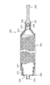
- FIG. 10 is a side view showing a part of the inflatable body 200 of the second embodiment broken.
- the inflatable body 200 of the second embodiment is arranged at the mandrel 210, the first metal member 230 arranged at one end of the mandrel 210, and the other end of the mandrel 210. It has a second metal member 240 and fibers 220 wound around them.
- the mandrel 210 includes a large diameter portion 211 formed in the middle portion in the axial direction, a tapered portion 212 and a medium diameter portion 213 formed on one end side in the axial direction, and a step portion 214 and a small diameter portion 215 formed on the other end side in the axial direction. , Are provided together.
- a protrusion 216 having a smaller diameter than the medium diameter portion 213 is formed on one end side in the axial direction of the medium diameter portion 213.
- the mandrel 210 is made of a resin member that can expand in the radial direction.
- the first metal member 230 is a so-called stub shaft and exhibits a substantially cylindrical shape. One end side of the first metal member 230 in the axial direction is exposed from the fiber 220. An annular flange portion 231 is formed in the axially intermediate portion of the first metal member 230. Further, a bottomed hole 232 is formed on the other end side of the first metal member 230 in the axial direction, and is externally fitted to the protruding portion 216 of the mandrel 210. The first metal member 230 is covered with fibers 220 from the other end side in the axial direction to a range beyond the flange portion 231.
- the second metal member 240 is a so-called collar and exhibits a substantially cylindrical shape.
- the other end side in the axial direction of the second metal member 240 is exposed from the fiber 220, and the one end side in the axial direction of the second metal member 240 is covered with the fiber 220. Further, the second metal member 240 is externally fitted to the step portion 214 of the mandrel 210.
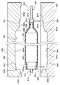
- FIG. 11 is a cross-sectional view showing a state in which the inflatable body 200 of the second embodiment is installed in the mold 260.
- FIG. 12 is an enlarged view of the XII portion of FIG.
- the mold 260 includes an upper mold 262 and a lower mold 263.
- the inflow gate 269a provided in the upper die 262 is provided at a position corresponding to the first metal member 230. More specifically, as shown in FIG. 12, the downstream end portion 269a1 of the inflow gate 269a is provided so as to open toward the portion of the first metal member 230 where the fiber 220 is not wound. ing. Further, a resin pool 269a2 is provided between the downstream end portion 269a1 of the inflow gate 269a and the end portion of the fiber 220.
- the upstream end portion 269b1 of the outflow gate 269b provided in the upper die 262 is provided at a position corresponding to the portion of the second metal member 240 around which the fiber 220 is wound.
- the upstream end portion 269b1 of the outflow gate 269b may be provided at a position corresponding to the portion of the second metal member 240 where the fiber 220 is not wound.
- the upper mold 262 is provided with a fluid passage 262c for supplying or extracting a fluid to the inside of the mandrel 210.
- the fluid passage 262c communicates with an opening provided at the end of the small diameter portion 215.
- the first metal member 230 is provided on one end side of the inflatable body 200, and the upper mold 262 contains the fiber 220 of the first metal member 230.
- An inflow gate 269a is provided at a position corresponding to the unwound portion. Then, in the inflow step, the resin flows from the inflow gate 269a toward the portion of the first metal member 230 where the fibers 220 are not wound. The resin that has flowed into the mold 260 is supplied to the fiber 220 via the resin pool 269a2. As a result, it is possible to prevent the arrangement of the fibers 220 from being disturbed by the flow of the resin flowing in from the inflow gate 269a.
- the other end side in the axial direction of the first metal member 230 and the one end side in the axial direction of the second metal member 240 are covered with the fibers 220. Therefore, by performing RTM molding, the first metal member 230 and the second metal member 240 and the fiber reinforced resin tube body are integrated. Since each step other than the inflow step is the same as that of the first embodiment, the description thereof will be omitted.
- FIG. 13A is a cross-sectional view of Modification 1 corresponding to the line XIII-XIII shown in FIG.
- the mold 260 of the first modification is provided with three recesses 268 at intervals of 90 degrees from the inflow gate 269a.
- three resin protrusions corresponding to the three recesses 268 are formed on the outer peripheral surface of the fiber-reinforced resin tube at 90-degree intervals.
- a resin convex portion as a gate mark remains at a position corresponding to the inflow gate 269a.
- the size of the resin convex portion as the gate mark is substantially constant with little variation among the molded products, the size of the resin convex portion as the gate mark is estimated in advance and the size of the three concave portions 268. Adjust the plastic. As a result, the resin convex portion as the gate mark and the three resin convex portions corresponding to the three concave portions 268 are formed with substantially the same size and at intervals of 90 degrees. As a result, the weight balance in the circumferential direction of the fiber-reinforced resin tube can be adjusted.
- the interval at which the recess 268 is provided is not limited to 90 degrees, and may be an equal interval from the inflow gate 269a.
- FIG. 13B is a cross-sectional view of Modification 2 corresponding to the line XIII-XIII shown in FIG.
- the mold 260 of the second modification is provided with three inflow gates 269a at intervals of 120 degrees in the circumferential direction of the fiber reinforced resin tube.
- resin protrusions as gate marks can be provided at intervals of 120 degrees in the circumferential direction of the fiber reinforced resin tube.
- the weight balance in the circumferential direction of the fiber-reinforced resin tube can be adjusted.
- the molding speed of the fiber-reinforced resin tube can be increased.
- the interval at which the inflow gate 269a is provided is not limited to 120 degrees, and may be an equal interval.
- the method for manufacturing a fiber-reinforced resin tube according to the third embodiment is mainly different from the first embodiment in that a stepped portion is formed at a portion corresponding to the metal member of the mold.
- a stepped portion is formed at a portion corresponding to the metal member of the mold.
- the inflatable body 300 of the third embodiment has a cylindrical mandrel 310, a first metal member 330 provided on one end side of the mandrel 310, and the other end side of the mandrel 310. It includes a second metal member 340 provided and a fiber 320 wound around the mandrel 310.
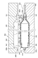
- the mold 360 of the third embodiment includes an upper mold 362 and a lower mold 363. In addition, in FIGS. 14 and 15, the description of various gates is omitted.
- the fiber 320 is wound in a layered and cylindrical shape to form a large diameter portion 322, a small diameter portion 324 provided on the first metal member 330 side with respect to the large diameter portion 322, and a large diameter portion 322. It constitutes a tapered portion 326 provided between the small diameter portion 324 and the tapered portion 326.
- the other end side 322a of the large diameter portion 322 overlaps with one end side of the second metal member 340. Further, the one end side 324a of the small diameter portion 324 overlaps with the other end side of the first metal member 330.
- the lower mold 363 is formed with a concave lower cavity portion 364 along the outer shape of the lower half portion of the inflatable body 300.
- the lower cavity portion 364 has a lower recess 364a for a large diameter portion, a lower recess 364c for a small diameter portion, and a lower recess for a tapered portion corresponding to the shape of the fiber 320 (more accurately, the shape of the fiber reinforced resin tube to be molded).
- the recess 364b, the lower recess 364d for the first metal member corresponding to the shape of the portion of the first metal member 330 where the fiber 320 is not wound, and the fiber 320 of the second metal member 340 are not wound.
- a first lower step portion Dd1 is formed at a boundary portion between the lower recess 364c for the small diameter portion and the lower recess 364d for the first metal member.
- a second lower step portion Dd2 is formed at the boundary portion between the lower recess 364a for the large diameter portion and the lower recess 364e for the second metal member.
- the upper mold 362 is formed with a concave upper cavity portion 365 along the outer shape of the upper half portion of the inflatable body 300.
- the upper cavity portion 365 includes an upper recess 365a for a large diameter portion, an upper recess 365c for a small diameter portion, and an upper recess 365b for a tapered portion according to the shape of the fiber portion 320, and the fiber 320 of the first metal member 330 is wound.
- a first upper step portion Du1 is formed at the boundary portion between the upper recess 365c for the small diameter portion and the upper recess 365d for the first metal member.
- a second upper step portion Du2 is formed at the boundary portion between the upper recess 365a for the large diameter portion and the upper recess 365e for the second metal member.
- the installation process in the method for manufacturing the fiber reinforced resin tube body according to the third embodiment includes the first installation process and the second installation process.
- the inflator 300 is installed in the lower mold 363 as shown by an arrow in FIG.
- the one end side 324a of the small diameter portion 324 is installed in line with the first lower step portion Dd1.
- the other end side 322a of the large diameter portion 322 is installed in line with the second lower step portion Dd2.
- the position of the inflatable body 300 in the axial direction can be accurately aligned with the lower mold 363.
- the portion of the first metal member 330 in which the fiber 320 is not wound is installed in the lower recess 364d for the first metal member.
- the portion of the second metal member 340 in which the fiber 320 is not wound is installed in the lower recess 364e for the second metal member.
- the radial position of the inflatable body 300 can be accurately aligned with the lower mold 363.
- the upper mold 362 is installed and the mold is fastened to the lower mold 363 in which the inflatable body 300 is installed.
- the first upper step portion Du1 of the upper die 362 is aligned with the one end side 324a of the small diameter portion 324
- the second upper step portion Du2 is aligned with the other end side 322a of the large diameter portion 322.
- the upper recess 365d for the first metal member is fitted to the portion of the first metal member 330 where the fiber 320 is not wound
- the second metal member 340 is provided with the second portion of the second metal member 340 where the fiber 320 is not wound. Align the upper recess 365e for the metal member.
- the first metal member 330 and the second metal member 340 are sandwiched between the upper die 362 and the lower die 363, so that the axis of the inflatable body 330 is accurately aligned with the axis of the fiber reinforced resin tube to be molded. Can be matched to.
- each step other than the installation step is the same as that of the first embodiment, so the description thereof will be omitted.
- the first metal member 330 and the second metal member 340 are provided on one end side and the other end side of the expansion body 300, respectively.
- the fiber 320 is also wound around a part of the first metal member 330 and the second metal member 340.
- the mold 360 is configured by combining a lower mold 363 as a first mold and an upper mold 362 as a second mold.
- the lower mold 363 has a lower recess 364d for the first metal member and a lower recess 364e for the second metal member at positions corresponding to the first metal member 330 and the second metal member 340, respectively.
- the upper die 362 has an upper recess 365d for the first metal member and an upper recess 365e for the second metal member.
- the lower recess 364d for the first metal member and the lower recess 364e for the second metal member have a first lower step portion Dd1 and a second lower step portion Dd2 at positions corresponding to both end portions 324a and 322a of the fiber 320.
- the upper recess 365d for the first metal member and the upper recess 365e for the second metal member have a first upper step portion Du1 and a second upper step portion Du2.
- the first metal member 330 and the second metal member 340 are aligned with the first lower step portion Dd1 and the second lower step portion Dd2, respectively, while both end portions 324a and 322a of the fiber 320 are aligned with the first lower step portion Dd1 and the second lower step portion Dd2.
- the first metal member while aligning the first installation step to be installed in the lower recess 364e for 364d and the second metal member and the first upper step portion Du1 and the second upper step portion Du2 with both end portions 324a and 322a of the fiber 320, respectively. It has a second installation step of installing the upper recess 365d and the upper recess 365e for the second metal member in the first metal member 330 and the second metal member 340.
- the portion of the first metal member 330 in which the fiber 320 is not wound is sandwiched between the lower recess 364d for the first metal member and the upper recess 365d for the first metal member, and the portion of the second metal member 340 is sandwiched between the lower recess 364d and the upper recess 365d for the first metal member.
- the portion where the fiber 320 is not wound is sandwiched between the lower recess 364e for the second metal member and the upper recess 365e for the second metal member, so that the expanded body is not affected by the layer thickness of the fiber 320 or the like.
- the axis of 300 can be accurately aligned with the axis of the fiber-reinforced resin tube.
- both end portions 324a and 322a of the fiber 320 are aligned with the first lower step portion Dd1 and the second lower step portion Dd2, so that the lower die 363 can be used.
- the axial position of the inflatable body 300 can be accurately matched.
- the mold is arranged so that the axial directions of the expanders installed in the mold intersect with each other in the horizontal direction. It is mainly different from the first embodiment. Hereinafter, the differences from the first embodiment will be described in detail.
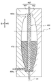
- FIG. 16 is a cross-sectional view showing an inflow process according to the fourth embodiment.
- the mold 460 is arranged so that the axis O1 of the expander 400 intersects the horizontal line H at 90 degrees.
- the axis O1 of the expander 400 installed in the mold 460 points in the vertical direction.
- the mold 460 is divided into a left mold 462 and a right mold 463, and an inflow gate 469a is provided on the lower side of the left mold 462 and an outflow gate 469b is provided on the upper side of the left mold 462.
- the resin 470 is flowed from the lower side of the mold 460 in the inflow step. Therefore, if bubbles are generated in the mold 460, the bubbles are blown. Can be pushed upward to allow air bubbles to escape from the outflow gate 469b. This makes it possible to suppress deterioration of product quality due to air bubbles.
- the expander 400 is compared with the case where the expander 400 is installed so that the axis O1 points in the horizontal direction. The deflection of 400 can be suppressed.
- the direction of the mold 460 is the direction in which the axis O1 of the expansion body 400 installed in the mold 460 intersects the horizontal line H at 90 degrees. Is preferable, but the present invention is not limited to this.
- the crossing angle of the axis O1 with respect to the horizon H can be appropriately set within a range in which the bubbles generated in the mold 460 can be pushed up. Except for the orientation of the mold in the inflow step in the fourth embodiment, the same as the first embodiment, and thus the description thereof will be omitted.
Landscapes
- Engineering & Computer Science (AREA)
- Mechanical Engineering (AREA)
- Chemical & Material Sciences (AREA)
- Composite Materials (AREA)
- Manufacturing & Machinery (AREA)
- Moulding By Coating Moulds (AREA)
- Casting Or Compression Moulding Of Plastics Or The Like (AREA)
Priority Applications (4)
| Application Number | Priority Date | Filing Date | Title |
|---|---|---|---|
| DE112021002951.7T DE112021002951T5 (de) | 2020-09-24 | 2021-09-16 | Verfahren zur herstellung eines rohrkörpers aus faserverstärktem harz |
| CN202180058404.4A CN116056876A (zh) | 2020-09-24 | 2021-09-16 | 纤维增强树脂管体的制造方法 |
| JP2022551927A JP7426680B2 (ja) | 2020-09-24 | 2021-09-16 | 繊維強化樹脂管体の製造方法 |
| US18/106,314 US20230182415A1 (en) | 2020-09-24 | 2023-02-06 | Method for manufacturing fiber-reinforced resin tube body |
Applications Claiming Priority (2)
| Application Number | Priority Date | Filing Date | Title |
|---|---|---|---|
| JP2020159548 | 2020-09-24 | ||
| JP2020-159548 | 2020-09-24 |
Related Child Applications (1)
| Application Number | Title | Priority Date | Filing Date |
|---|---|---|---|
| US18/106,314 Continuation US20230182415A1 (en) | 2020-09-24 | 2023-02-06 | Method for manufacturing fiber-reinforced resin tube body |
Publications (1)
| Publication Number | Publication Date |
|---|---|
| WO2022065179A1 true WO2022065179A1 (ja) | 2022-03-31 |
Family
ID=80846633
Family Applications (1)
| Application Number | Title | Priority Date | Filing Date |
|---|---|---|---|
| PCT/JP2021/034043 Ceased WO2022065179A1 (ja) | 2020-09-24 | 2021-09-16 | 繊維強化樹脂管体の製造方法 |
Country Status (5)
| Country | Link |
|---|---|
| US (1) | US20230182415A1 (https=) |
| JP (1) | JP7426680B2 (https=) |
| CN (1) | CN116056876A (https=) |
| DE (1) | DE112021002951T5 (https=) |
| WO (1) | WO2022065179A1 (https=) |
Cited By (1)
| Publication number | Priority date | Publication date | Assignee | Title |
|---|---|---|---|---|
| GB2618540B (en) * | 2022-05-09 | 2024-11-20 | Pulpex Ltd | A receptacle forming system |
Citations (3)
| Publication number | Priority date | Publication date | Assignee | Title |
|---|---|---|---|---|
| JP2008155383A (ja) * | 2006-12-20 | 2008-07-10 | Toyota Industries Corp | 繊維強化プラスチックの製造方法 |
| JP2012052588A (ja) * | 2010-08-31 | 2012-03-15 | Universal Shipbuilding Corp | 圧力容器の製造法および圧力容器 |
| JP6873369B1 (ja) * | 2020-06-26 | 2021-05-19 | 日立Astemo株式会社 | 繊維強化樹脂製管体の製造方法 |
Family Cites Families (12)
| Publication number | Priority date | Publication date | Assignee | Title |
|---|---|---|---|---|
| JPS6122926A (ja) * | 1984-07-10 | 1986-01-31 | Sumitomo Electric Ind Ltd | 繊維強化プラスチツクス製円筒体の製造方法 |
| JPH07223271A (ja) * | 1993-12-16 | 1995-08-22 | Toray Ind Inc | 曲がり管とその製造方法および装置 |
| DE69424047T2 (de) * | 1994-03-24 | 2000-10-26 | Toray Industries, Inc. | Gekrümmte röhre, verfahren und apparat zur herstellung |
| JPH08323870A (ja) | 1995-05-31 | 1996-12-10 | Toyota Autom Loom Works Ltd | 繊維強化複合材の成形用金型 |
| JP4846103B2 (ja) * | 2001-02-07 | 2011-12-28 | 三菱レイヨン株式会社 | 繊維強化樹脂パイプ及びこれを用いた動力伝達シャフト |
| RU2258002C2 (ru) * | 2001-03-02 | 2005-08-10 | Манфред А. А. ЛЮПКЕ | Способ и устройство для изготовления термопластичной трубы с двойными стенками и соединительной муфтой |
| CN1492801A (zh) * | 2001-03-13 | 2004-04-28 | �Ϻ���ͨ��ѧ | 制造空心复合件的非等温方法 |
| JP2003127257A (ja) | 2001-10-23 | 2003-05-08 | Toho Tenax Co Ltd | 繊維強化樹脂管状体とその製造方法 |
| JP2010064392A (ja) * | 2008-09-11 | 2010-03-25 | Toyota Motor Corp | 繊維強化プラスチックの製造方法および製造装置 |
| FR2967606B1 (fr) * | 2010-11-19 | 2014-04-18 | Peugeot Citroen Automobiles Sa | Procede de fabrication d'un ressort en materiau composite, tel qu'un ressort de suspension notamment pour vehicule automobile |
| CN104760303B (zh) * | 2014-01-07 | 2018-10-19 | 北京玻钢院复合材料有限公司 | 一种固体火箭发动机绝热扩散段灌注方法 |
| US20200094455A1 (en) * | 2017-03-23 | 2020-03-26 | Kyb Corporation | Outer cylinder for hydraulic shock absorber and method of molding the outer cylinder for the hydraulic shock absorber |
-
2021
- 2021-09-16 WO PCT/JP2021/034043 patent/WO2022065179A1/ja not_active Ceased
- 2021-09-16 DE DE112021002951.7T patent/DE112021002951T5/de active Pending
- 2021-09-16 CN CN202180058404.4A patent/CN116056876A/zh active Pending
- 2021-09-16 JP JP2022551927A patent/JP7426680B2/ja active Active
-
2023
- 2023-02-06 US US18/106,314 patent/US20230182415A1/en active Pending
Patent Citations (3)
| Publication number | Priority date | Publication date | Assignee | Title |
|---|---|---|---|---|
| JP2008155383A (ja) * | 2006-12-20 | 2008-07-10 | Toyota Industries Corp | 繊維強化プラスチックの製造方法 |
| JP2012052588A (ja) * | 2010-08-31 | 2012-03-15 | Universal Shipbuilding Corp | 圧力容器の製造法および圧力容器 |
| JP6873369B1 (ja) * | 2020-06-26 | 2021-05-19 | 日立Astemo株式会社 | 繊維強化樹脂製管体の製造方法 |
Cited By (1)
| Publication number | Priority date | Publication date | Assignee | Title |
|---|---|---|---|---|
| GB2618540B (en) * | 2022-05-09 | 2024-11-20 | Pulpex Ltd | A receptacle forming system |
Also Published As
| Publication number | Publication date |
|---|---|
| CN116056876A (zh) | 2023-05-02 |
| US20230182415A1 (en) | 2023-06-15 |
| JPWO2022065179A1 (https=) | 2022-03-31 |
| DE112021002951T5 (de) | 2023-04-06 |
| JP7426680B2 (ja) | 2024-02-02 |
Similar Documents
| Publication | Publication Date | Title |
|---|---|---|
| US3970495A (en) | Method of making a tubular shaft of helically wound filaments | |
| US12296548B2 (en) | Method for manufacturing tube body made of fiber-reinforced resin | |
| JP2021102994A (ja) | 高圧タンクの製造方法 | |
| EP2038100B1 (en) | Method and moulding core for producing a fibre composite component for aviation and spaceflight | |
| US10995909B2 (en) | Hydrogen tank body and method of producing the same, and hydrogen tank and method of producing the same | |
| CN107709794A (zh) | 用于制造气囊式蓄能器的方法以及根据该方法制造的气囊式蓄能器 | |
| EP2186614B1 (en) | Fiber-reinforced resin hollow part with flange and method of forming the same | |
| JP4384221B2 (ja) | 繊維強化樹脂中空部品の成形方法 | |
| JP7426680B2 (ja) | 繊維強化樹脂管体の製造方法 | |
| US20210180645A1 (en) | Method for manufacturing tube body used in power transmission shaft | |
| US20220288872A1 (en) | Method for manufacturing structure and structure | |
| WO2023187965A1 (ja) | 炭素繊維固定治具、炭素繊維強化樹脂管体の製造方法及び動力伝達軸 | |
| CN111070519A (zh) | 一种柔性膨胀装置及其制作方法 | |
| JP2015071239A (ja) | Frp成形品の製造方法および成形型 | |
| US20250297696A1 (en) | Method of producing tube body | |
| JP3690744B2 (ja) | 繊維強化プラスチック部品の製造方法 | |
| US12220880B2 (en) | Method for producing tube body | |
| JP7765259B2 (ja) | 繊維強化樹脂管体の製造方法 | |
| JP2016144923A (ja) | サンドイッチ成形体およびその成形方法ならびに成形装置 | |
| JP7503472B2 (ja) | 繊維強化樹脂製構造物の製造に用いられる型及び繊維強化樹脂製構造物の製造方法 | |
| EP3546201B1 (en) | Methods and systems for manufacturing composite components | |
| JP7190614B1 (ja) | 推進軸用炭素繊維強化樹脂製筒体 | |
| JP7812206B2 (ja) | 繊維強化樹脂製構造物の製造方法 | |
| RU2233744C2 (ru) | Способ изготовления крупногабаритного композитного бака | |
| JP6581739B1 (ja) | マンドレル |
Legal Events
| Date | Code | Title | Description |
|---|---|---|---|
| 121 | Ep: the epo has been informed by wipo that ep was designated in this application |
Ref document number: 21872309 Country of ref document: EP Kind code of ref document: A1 |
|
| ENP | Entry into the national phase |
Ref document number: 2022551927 Country of ref document: JP Kind code of ref document: A |
|
| 122 | Ep: pct application non-entry in european phase |
Ref document number: 21872309 Country of ref document: EP Kind code of ref document: A1 |