WO2022065170A1 - 光学フィルタ - Google Patents
光学フィルタ Download PDFInfo
- Publication number
- WO2022065170A1 WO2022065170A1 PCT/JP2021/034011 JP2021034011W WO2022065170A1 WO 2022065170 A1 WO2022065170 A1 WO 2022065170A1 JP 2021034011 W JP2021034011 W JP 2021034011W WO 2022065170 A1 WO2022065170 A1 WO 2022065170A1
- Authority
- WO
- WIPO (PCT)
- Prior art keywords
- wavelength
- transmittance
- incident angle
- degrees
- 0deg
- Prior art date
- Legal status (The legal status is an assumption and is not a legal conclusion. Google has not performed a legal analysis and makes no representation as to the accuracy of the status listed.)
- Ceased
Links
Images


Classifications
-
- G—PHYSICS
- G02—OPTICS
- G02B—OPTICAL ELEMENTS, SYSTEMS OR APPARATUS
- G02B5/00—Optical elements other than lenses
- G02B5/20—Filters
- G02B5/22—Absorbing filters
-
- G—PHYSICS
- G02—OPTICS
- G02B—OPTICAL ELEMENTS, SYSTEMS OR APPARATUS
- G02B5/00—Optical elements other than lenses
- G02B5/20—Filters
- G02B5/28—Interference filters
Definitions
- the present invention relates to an optical filter that transmits light in the visible wavelength region and blocks light in the ultraviolet wavelength region and the near infrared wavelength region.
- the image pickup device using the solid-state image pickup element transmits light in the visible region (hereinafter, also referred to as “visible light”) and transmits light in the ultraviolet wavelength region (hereinafter, “ultraviolet”).
- visible light also referred to as “visible light”
- ultraviolet wavelength region hereinafter, “ultraviolet”
- An optical filter that blocks light (also referred to as “light”) or light in the near-infrared wavelength region hereinafter also referred to as “near-infrared light” is used.
- dielectric thin films having different refractive indexes are alternately laminated on one side or both sides of a transparent substrate (dielectric multilayer film), and reflection that reflects the light to be shielded by utilizing the interference of light is used.
- a transparent substrate dielectric multilayer film
- reflection that reflects the light to be shielded by utilizing the interference of light is used.
- Various methods such as type filters can be mentioned.
- the human visual sensitivity is up to about 700 nm, while the sensitivity of the image sensor mounted on the image pickup device is up to about 1200 nm. If light enters the sensor without shading the near-infrared region after 700 nm, there is a concern that the image reproducibility may deteriorate, unlike what the image looks through the human eye. In order to bring the sensitivity ranges closer to each other and correct the color tone, there is a demand for an optical filter that blocks light in the near-infrared light wavelength region, particularly in the wavelength region of 1000 to 1200 nm.
- the optical film thickness of the dielectric multilayer film changes depending on the incident angle of light, so that the spectral transmission curve changes depending on the incident angle and high reflectance is obtained at a high incident angle.
- the problem is that the ultraviolet light and the near-infrared light to be obtained have high transmittance, and noise is generated by the ultraviolet light and the near-infrared light reflected by the dielectric multilayer film.
- the spectral sensitivity of the solid-state image sensor may be affected by the incident angle. In particular, it is expected to be used under high incident angle conditions due to the recent decrease in camera module height. Therefore, there has been a demand for an optical filter that blocks ultraviolet light and near-infrared light without substantially affecting the transmittance of visible light and without depending on the incident angle.
- Patent Document 1 describes an optical filter having an average transmittance of 5% or less in a wavelength region of 1100 to 1200 nm.
- the optical filter described in Patent Document 1 achieves a low transmittance in the range by adding a dye having an absorption band in the wavelength range of 1100 to 1200 nm, but the dye also has an absorption band in the visible region. Therefore, not only the long wavelength region but also the transmittance in the visible region is lowered.
- the present invention has high transparency of visible light, high shielding property of light in the wavelength range of 1000 to 1200 nm, and suppression of deterioration of shielding property of ultraviolet light and near infrared light at a high incident angle.
- the purpose is to provide a filter.
- the present invention provides an optical filter having the following configuration.
- An optical filter including a base material and a dielectric multilayer film laminated as an outermost layer on at least one main surface side of the base material.
- the substrate has a resin film containing a dye (U) having a maximum absorption wavelength of 380 to 425 nm in dichloromethane, a dye (A) having a maximum absorption wavelength of 690 to 730 nm in dichloromethane, and a resin.
- U a dye having a maximum absorption wavelength of 380 to 425 nm in dichloromethane
- A having a maximum absorption wavelength of 690 to 730 nm in dichloromethane
- a resin containing a dye (U) having a maximum absorption wavelength of 380 to 425 nm in dichloromethane, a dye (A) having a maximum absorption wavelength of 690 to 730 nm in dichloromethane, and a resin.
- Average transmittance T 1000-1200 (40deg) AVE in the spectral transmittance curve at 40 degrees is 10% or less (i-3)
- Average transmittance T 440 in the spectral transmittance curve at a wavelength of 440 to 600 nm and an incident angle of 0 degrees -600 (0 deg) AVE is 90% or more (i-4)
- Average transmittance in the spectral transmittance curve at a wavelength of 440 to 600 nm and an incident angle of 40 degrees T 440-600 (40 deg) AVE is 83% or more (i-5) )
- the wavelength UV50 (0deg) at which the transmittance is 50% at an incident angle of 0 degrees is in the range of 420 to 435 nm (i-6) when the transmittance is 20% at a wavelength of 350 to 450 nm and an incident angle of 0 degrees.
- the wavelength of is UV20 (0deg)
- the wavelength when the transmittance is 40% is UV40 (0deg)
- the wavelength when the transmittance is 50% is UV50 (0deg )
- the wavelength when the transmittance is 20% is UV20 (40 deg)
- the wavelength when the transmittance is 40% is UV40 (40 deg)
- the wavelength when the transmittance is 50% is UV20 (40 deg)
- UV50 (40 deg) When UV50 (40 deg) is set to The absolute value of the difference between UV20 (0deg) and UV20 (40deg) is 12 nm or less, The absolute value of the difference between UV40 (0deg) and UV40 (40deg) is 12 nm or less, The wavelength when the absolute value of the difference between UV50 (0deg) and UV50 (40deg) is 12 nm or less (i-7) at a wavelength of 640 to 700 nm and the incident angle is 0 degrees and the transmittance is 20% is set to IR20 (0deg) .
- the wavelength when the transmittance is 20% is IR20 (40 deg)
- the absolute value of the difference between IR20 (0deg) and IR20 (40deg) is 15 nm or less (i-8).
- the wavelength IR20 (0deg) at which the transmittance is 20% at an incident angle of 0 degrees is in the range of 640 to 700 nm.
- the present invention has high transparency of visible light, high shielding property of light in the wavelength range of 1000 to 1200 nm, and suppression of deterioration of shielding property of ultraviolet light and near infrared light at a high incident angle is suppressed.
- Optical filters can be provided.
- FIG. 1 is a cross-sectional view schematically showing an example of an optical filter of one embodiment.
- FIG. 2 is a cross-sectional view schematically showing another example of the optical filter of one embodiment.
- FIG. 3 is a cross-sectional view schematically showing another example of the optical filter of one embodiment.
- FIG. 4 is a cross-sectional view schematically showing another example of the optical filter of one embodiment.
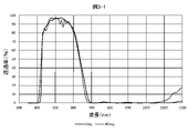
- FIG. 5 is a diagram showing a spectral transmittance curve of the optical filter of Example 3-1.
- the near-infrared absorbing dye may be abbreviated as "NIR dye” and the ultraviolet absorbing dye may be abbreviated as "UV dye”.
- NIR dye near-infrared absorbing dye
- UV dye ultraviolet absorbing dye
- the compound represented by the formula (I) is referred to as a compound (I).
- the dye composed of compound (I) is also referred to as dye (I), and the same applies to other dyes.
- the group represented by the formula (I) is also referred to as a group (I), and the same applies to the groups represented by other formulas.
- the internal transmittance is a transmittance obtained by subtracting the influence of interfacial reflection from the actually measured transmittance represented by the formula ⁇ measured transmittance / (100-reflectance) ⁇ ⁇ 100.
- the transmittance of the base material and the spectroscopy of the transmittance of the resin film including the case where the dye is contained in the resin are all "internal transmittance" even when it is described as "transmittance”.
- the transmittance measured by dissolving the dye in a solvent such as dichloromethane and the transmittance of the optical filter having the dielectric multilayer film are the measured transmittances.
- a transmittance of 90% or more means that the transmittance does not fall below 90% in the entire wavelength region, that is, the minimum transmittance is 90% or more in the wavelength region.
- a transmittance of 1% or less means that the transmittance does not exceed 1% in the entire wavelength region, that is, the maximum transmittance is 1% or less in the wavelength region. ..
- the average transmittance and the average internal transmittance in a specific wavelength range are arithmetic means of the transmittance and the internal transmittance for each 1 nm in the wavelength range.
- "-" representing a numerical range includes an upper and lower limit.
- the optical filter of one embodiment of the present invention includes a base material and a dielectric multilayer film laminated as an outermost layer on at least one main surface side of the base material, which will be described later.
- the base material is a resin film containing a dye (U) having a maximum absorption wavelength of 380 to 425 nm in dichloromethane, a dye (A) having a maximum absorption wavelength of 690 to 730 nm in dichloromethane, and a resin.
- the dye (U) is a UV dye and the dye (A) is a NIR dye.
- the base material contains a dye that absorbs ultraviolet rays and near infrared rays, the spectral characteristics of the dielectric multilayer film at a high incident angle are deteriorated, for example, light loss and noise are generated in the ultraviolet region and the near infrared region. It can be suppressed by the absorption characteristics of the material.
- a dye that absorbs ultraviolet rays and near infrared rays the spectral characteristics of the dielectric multilayer film at a high incident angle are deteriorated, for example, light loss and noise are generated in the ultraviolet region and the near infrared region. It can be suppressed by the absorption characteristics of the material.
- Each dye and resin will be described later.
- FIG. 1 are sectional views schematically showing an example of an optical filter of one embodiment.
- the optical filter 1A shown in FIG. 1 is an example in which the dielectric multilayer film 30 is provided on one main surface side of the base material 10.
- “having a specific layer on the main surface side of the base material” is not limited to the case where the layer is provided in contact with the main surface of the base material, and another function is provided between the base material and the layer. Including cases where layers are provided.
- the optical filter 1B shown in FIG. 2 is an example in which the dielectric multilayer film 30 is provided on both main surface sides of the base material 10.
- the optical filter 1C shown in FIG. 3 is an example in which the base material 10 has a support 11 and a resin film 12 laminated on one main surface side of the support 11.
- the optical filter 1C further has a dielectric multilayer film 30 on the resin film 12 and on the main surface side of the support 11 on which the resin film 12 is not laminated.
- the optical filter 1D shown in FIG. 4 is an example in which the base material 10 has a support 11 and a resin film 12 laminated on both main surface sides of the support 11.
- the optical filter 1D further has a dielectric multilayer film 30 on each resin film 12.
- the optical filter of the present invention satisfies all of the following spectral characteristics (i-1) to (i-8).
- Average transmittance T 1000-1200 (40deg) AVE in the spectral transmittance curve at 40 degrees is 10% or less (i-3)
- Average transmittance T 440 in the spectral transmittance curve at a wavelength of 440 to 600 nm and an incident angle of 0 degrees -600 (0 deg) AVE is 90% or more (i-4)
- Average transmittance in the spectral transmittance curve at a wavelength of 440 to 600 nm and an incident angle of 40 degrees T 440-600 (40 deg) AVE is 83% or more (i-5) )
- the wavelength UV50 (0deg) at which the transmittance is 50% at an incident angle of 0 degrees is in the range of 420 to 435 nm (i-6) when the transmittance is 20% at a wavelength of 350 to 450 nm and an incident angle of 0 degrees.
- the wavelength of is UV20 (0deg)
- the wavelength when the transmittance is 40% is UV40 (0deg)
- the wavelength when the transmittance is 50% is UV50 (0deg )
- the wavelength when the transmittance is 20% is UV20 (40 deg)
- the wavelength when the transmittance is 40% is UV40 (40 deg)
- the wavelength when the transmittance is 50% is UV20 (40 deg)
- UV50 (40 deg) When UV50 (40 deg) is set to The absolute value of the difference between UV20 (0deg) and UV20 (40deg) is 12 nm or less, The absolute value of the difference between UV40 (0deg) and UV40 (40deg) is 12 nm or less, The wavelength when the absolute value of the difference between UV50 (0deg) and UV50 (40deg) is 12 nm or less (i-7) at a wavelength of 640 to 700 nm and the incident angle is 0 degrees and the transmittance is 20% is set to IR20 (0deg) .
- the wavelength when the transmittance is 20% is IR20 (40 deg)
- the absolute value of the difference between IR20 (0deg) and IR20 (40deg) is 15 nm or less (i-8).
- the wavelength IR20 (0deg) at which the transmittance is 20% at an incident angle of 0 degrees is in the range of 640 to 700 nm.
- This filter which satisfies all of the spectral characteristics (i-1) to (i-8), has high transmission of visible light, high shielding property of light in the wavelength region of 1000 to 1200 nm, and ultraviolet light at a high incident angle. It is an optical filter that suppresses the deterioration of the shielding property of near-infrared light.
- T 1000-1200 (0 deg) AVE is preferably 1% or less, more preferably 0.7% or less.
- T 1000-1200 (40 deg) AVE is preferably 8% or less, more preferably 7% or less.
- T 440-600 (0 deg) AVE is preferably 91% or more, more preferably 92% or more.
- T 440-600 (40 deg) AVE is preferably 85% or more, more preferably 88% or more.
- the spectral characteristic (i-5) means that the UV cut band shifts from the long wavelength, thereby enhancing the shielding property in the wavelength region of 1000 to 1200 nm.
- UV50 (0deg) is preferably in the range of 420-430 nm.
- the absolute value of the difference between UV20 (0deg) and UV20 (40deg) is preferably 10 nm or less, more preferably 9 nm or less, and UV40 (0deg) and UV40 (40deg).
- the absolute value of the difference is preferably 10 nm or less, more preferably 9 nm or less, and the absolute value of the difference between UV50 (0 deg) and UV50 (40 deg) is preferably 8 nm or less, more preferably 7 nm or less.
- the absolute value of the difference between IR20 (0 deg) and IR20 (40 deg) is preferably 13 nm or less, more preferably 12 nm or less.
- IR20 (0deg) is preferably in the range of 650 to 680 nm.
- the optical filter of the present invention further satisfies the following spectral characteristics (i-9).
- spectral characteristics (i-9) When the wavelength is 350 to 450 nm and the incident angle is 0 degrees, the wavelength when the transmittance is 10% is UV10 (0deg) , and the wavelength when the transmittance is 50% is UV50 (0deg ) .
- the absolute value of the difference between UV10 (0deg ) and UV50 ( 0deg) is 15 nm or less.
- the spectral characteristic (i-9) means that the slope of the spectral transmission curve is steep in the UV absorption start band having a wavelength of 350 to 450 nm.
- the spectral characteristic (i-9) is more preferably 8 nm or less, and particularly preferably 7 nm or less.
- the base material is provided with an ability to absorb ultraviolet light and near-infrared light, and the above-mentioned spectral characteristics (i-1) to (i-1) are determined by the absorption characteristics of the base material and the reflection characteristics of the dielectric multilayer film. Designed to meet i-8).
- the dielectric multilayer film is laminated as the outermost layer on at least one main surface side of the substrate.
- the dielectric multilayer film satisfies all of the following spectral characteristics (iv-1) to (iv-8).
- iv-1 The wavelength UV50 (0deg) at which the transmittance is 50% at an incident angle of 0 degrees is in the range of 420 to 430 nm.
- Iv-2) The spectral transmittance at a wavelength of 440 to 600 nm and an incident angle of 0 degrees.
- Average transmittance T 440-600 (0 deg) AVE on the curve is 90% or more (iv-3) Minimum transmittance T 440-600 (0 deg) MIN on the spectral transmittance curve at a wavelength of 440 to 600 nm and an incident angle of 0 degrees Average transmittance T440-600 (40deg) AVE in the spectral transmittance curve at 90% or more (iv-4) wavelength 440 to 600 nm and incident angle 40 degrees is 90% or more (iv-5) wavelength 440 to 600 nm and incident.
- the wavelength IR20 (0deg) at which the transmittance is 20% at an incident angle of 0 degrees is 680.
- Average transmittance T 1000-1200 (0deg) AVE in the spectral transmittance curve at (iv-7) wavelengths in the range of 740 nm to 1000 to 1200 nm and incident angle of 0 degrees is 1.5% or less (iv-8) wavelengths.
- Average transmittance T 1000-1200 (40 deg) AVE in the spectral transmittance curve at 1000 to 1200 nm and an incident angle of 40 degrees is 10% or less.
- UV50 (0deg) is preferably in the range of 420-427 nm.
- T 440-600 (0 deg) AVE is preferably 91% or more, more preferably 92% or more.
- the T 440-600 (0 deg) MIN is preferably 91% or more, more preferably 92% or more.
- T 440-600 (40 deg) AVE is preferably 91% or more, more preferably 92% or more.
- the T 440-600 (40 deg) MIN is preferably 82% or more, more preferably 85% or more.
- IR20 (0deg) is preferably in the range of 660 to 700 nm, more preferably in the range of 660 to 690 nm.
- T 1000-1200 (0 deg) AVE is preferably 1.2% or less, more preferably 1% or less.
- T 1000-1200 (40 deg) AVE is preferably 9% or less, more preferably 8% or less.
- the entire light-shielding band can be shifted to the long wavelength side or the short wavelength side by adjusting the film thickness of the multilayer film or the like.
- the present invention by shifting the entire light-shielding band of the multilayer film to the long wavelength side as shown in the characteristic (iv-1) and the characteristic (iv-6), 1000 to 1200 nm as shown in the characteristic (iv-7).
- the band can be shielded by the multilayer film.
- spectral characteristics (i-1) an optical filter having an excellent light-shielding property of 1000 to 1200 nm can be obtained.
- the resin film contains a UV dye that satisfies the spectral characteristics (ii-1) described later, that is, a UV dye having a steep slope of the spectral transmission curve in the UV absorption band having a wavelength of 400 to 430 nm, which will be described later.
- a resin film satisfying the spectral characteristics (iii-4), that is, a resin film having a steep slope of the spectral transmission curve in the UV absorption band having a wavelength of 400 to 430 nm can be obtained.
- an optical filter in which the oblique incident shift in the ultraviolet light region is suppressed can be obtained as shown in the spectral characteristics (i-6).
- At least one of the dielectric multilayer films is designed as a near-infrared reflective layer (hereinafter, also referred to as an NIR reflective layer).
- the other side of the dielectric multilayer film is preferably designed as a NIR reflective layer, a reflective layer having a reflective region other than the near infrared region, or an antireflection layer.
- the NIR reflective layer is a dielectric multilayer film designed to shield light in the near infrared region.
- the NIR reflective layer has, for example, wavelength selectivity that transmits visible light and mainly reflects light in the near infrared region other than the light shielding region of the resin film that is the absorption layer.
- the reflection region of the NIR reflection layer may include a light-shielding region in the near-infrared region of the resin film.
- the NIR reflection layer is not limited to the NIR reflection characteristic, and may be appropriately designed to have specifications for further blocking light in a wavelength range other than the near-infrared region, for example, the near-ultraviolet region.
- the NIR reflective layer is composed of, for example, a dielectric multilayer film in which a low refractive index dielectric film (low refractive index film) and a high refractive index dielectric film (high refractive index film) are alternately laminated.
- the high refractive index film preferably has a refractive index of 1.6 or more, more preferably 2.2 to 2.5.
- Examples of the material of the high refractive index film include Ta 2 O 5 , TIO 2 , and Nb 2 O 5 . Of these, TiO 2 is preferable from the viewpoints of film formation property, reproducibility in refractive index and the like, stability and the like.
- the low refractive index film preferably has a refractive index of less than 1.6, more preferably 1.45 or more and less than 1.55.
- the material of the low refractive index film include SiO 2 , SiO x N y and the like. SiO 2 is preferable from the viewpoint of reproducibility, stability, economy and the like in terms of film forming property.
- the wavelength of the light-shielding band can be lengthened by increasing the film thickness without changing the film thickness ratio of silica and titania constituting the multilayer film. Specifically, the thicknesses of silica and titania can be increased by 1 to 8% to adjust to a desired light-shielding band.
- the light-shielding band is shifted to the long wavelength side, and the light-shielding region is 1000 to 1200 nm.
- the total number of laminated dielectric multilayer films constituting the reflective layer is preferably 20 or more, more preferably. It is 30 layers or more, more preferably 35 layers or more. With such a number of layers, it is also preferable that the dielectric multilayer film can shield the region of 1000 to 1200 nm from light, and the transmittance can change sharply in the boundary wavelength region between the transmission region and the light-shielding region.
- the total number of layers is preferably 100 layers or less, more preferably 75 layers or less, and even more preferably 60 layers or less.
- the film thickness of the reflective layer is preferably 2 to 10 ⁇ m as a whole.
- the NIR reflective layer can satisfy the requirements for miniaturization, and can suppress the dependence on the incident angle while maintaining high productivity.
- a vacuum film forming process such as a CVD method, a sputtering method, or a vacuum vapor deposition method, or a wet film forming process such as a spray method or a dip method can be used.
- one layer may give predetermined optical characteristics, or two layers may give predetermined optical characteristics.
- each reflective layer may have the same configuration or a different configuration.
- it is usually composed of a plurality of reflective layers having different reflection bands.
- one is a near-infrared reflective layer that shields light in the short wavelength band of the near-infrared region, and the other is both the long-wavelength band and the near-ultraviolet region in the near-infrared region. It may be used as a near-infrared / near-ultraviolet reflective layer that shields the light of.
- the antireflection layer examples include a dielectric multilayer film, an intermediate refractive index medium, and a moth-eye structure in which the refractive index gradually changes. Of these, a dielectric multilayer film is preferable from the viewpoint of optical efficiency and productivity.
- the antireflection layer is obtained by alternately laminating dielectric multilayer films in the same manner as the reflection layer.
- the base material has a dye (U) and a resin film containing the dye (A) and a resin described later.
- the resin film satisfies all of the following spectral characteristics (iii-1) to (iii-6).
- iii-3) The wavelength UV50 at which the internal transmittance is 50% is in the range of 415 to 440 nm.
- the wavelength when the internal transmittance is 10% is UV10, and the internal transmittance.
- the absolute value of the difference between UV10 and UV50 is 15 nm or less (iii-5).
- the average internal transmittance T 440-550AVE in the spectral transmittance curve at a wavelength of 440 to 550 nm is 93% or more (iii-6).
- the internal transmittance is 20.
- the wavelength IR20 to be% is in the range of 650 to 700 nm.
- T 400 is preferably 1.5% or less, more preferably 1% or less.
- T 400-420AVE is preferably 4.5% or less, more preferably 4% or less.
- UV50 is preferably in the range of 420-435 nm.
- the slope of the spectral transmission curve is steep in the UV absorption start band having a wavelength of 400 to 430 nm.
- the spectral characteristic (iii-4) is preferably 14 nm or less, more preferably 13 nm or less.
- T 440-550AVE is preferably 94% or more, more preferably 95% or more.
- IR20 is preferably in the range of 660 to 690 nm.
- the resin film further satisfies the following spectral characteristics (iii-7) and (iii-8).
- (Iii-7) Average internal transmittance T 350-390AVE in the spectral transmittance curve at a wavelength of 350 to 390 nm is 10% or less
- T 350-390AVE is preferably 9% or less, more preferably 8% or less.
- T 400-430AVE is preferably 14% or less, more preferably 13% or less.
- the dye (U) is a UV dye having a maximum absorption wavelength of 380 to 425 nm in dichloromethane. By containing such a dye, ultraviolet light can be effectively cut.
- the dye (U) has a maximum absorption wavelength in dichloromethane, preferably 385 to 420 nm, more preferably 390 to 420 nm.
- the dye (U) preferably satisfies the following spectral characteristics (ii-1).
- spectral characteristics ii-1).
- the absolute value of the difference between UV10 and UV50 is preferably 18 nm or less, more preferably 16 nm or less.
- Examples of the dye (U) include oxazole dye, merocyanine dye, cyanine dye, naphthalimide dye, oxadiazole dye, oxazine dye, oxazolidine dye, naphthalic acid dye, styryl dye, anthracene dye, cyclic carbonyl dye, triazole dye and the like. Be done. Of these, the merocyanine pigment is particularly preferable. In addition, one type may be used alone, or two or more types may be used in combination.
- the dye (U) the merocyanine dye represented by the following formula (M) is particularly preferable.
- R 1 represents a monovalent hydrocarbon group having 1 to 12 carbon atoms which may have a substituent.
- substituent an alkoxy group, an acyl group, an acyloxy group, a cyano group, a dialkylamino group or a chlorine atom is preferable.
- the alkoxy group, acyl group, acyloxy group and dialkylamino group preferably have 1 to 6 carbon atoms.
- a part of the hydrogen atom may be substituted with an aliphatic ring, an aromatic ring or an alkenyl group, an alkyl group having 1 to 12 carbon atoms, and a part of the hydrogen atom. May be substituted with an aromatic ring, an alkyl group or an alkenyl group, a cycloalkyl group having 3 to 8 carbon atoms, and a part of the hydrogen atom may be substituted with an aliphatic ring, an alkyl group or an alkenyl group.
- An aryl group having 6 to 12 carbon atoms is preferable.
- R 1 is an unsubstituted alkyl group
- the alkyl group may be linear or branched, and the number of carbon atoms thereof is more preferably 1 to 6.
- R 1 is an alkyl group having 1 to 12 carbon atoms in which a part of the hydrogen atom is substituted with an aliphatic ring, an aromatic ring or an alkenyl group, 1 to 1 to 12 carbon atoms having a cycloalkyl group having 3 to 6 carbon atoms.
- An alkyl group of 4 and an alkyl group having 1 to 4 carbon atoms substituted with a phenyl group are more preferable, and an alkyl group having 1 or 2 carbon atoms substituted with a phenyl group is particularly preferable.
- the alkyl group substituted with an alkenyl group means an alkenyl group as a whole but does not have an unsaturated bond between the 1st and 2nd positions, and refers to, for example, an allyl group, a 3-butenyl group, or the like.
- R 1 is an alkyl group having 1 to 6 carbon atoms in which a part of the hydrogen atom may be substituted with a cycloalkyl group or a phenyl group.
- Particularly preferable Q 1 is an alkyl group having 1 to 6 carbon atoms, and specific examples thereof include a methyl group, an ethyl group, an n-propyl group, an isopropyl group, an n-butyl group, an isobutyl group and a t-butyl group. Be done.
- R2 to R5 independently represent a hydrogen atom, a halogen atom, an alkyl group having 1 to 10 carbon atoms, or an alkoxy group having 1 to 10 carbon atoms.
- the number of carbon atoms of the alkyl group and the alkoxy group is preferably 1 to 6, and more preferably 1 to 4.
- At least one of R 2 and R 3 is preferably an alkyl group, and it is more preferable that both are alkyl groups. If R 2 and R 3 are not alkyl groups, a hydrogen atom is more preferred. As R 2 and R 3 , both alkyl groups having 1 to 6 carbon atoms are particularly preferable.
- At least one of R 4 and R 5 is preferably a hydrogen atom, and both are more preferably a hydrogen atom.
- R 4 or R 5 is not a hydrogen atom, an alkyl group having 1 to 6 carbon atoms is preferable.
- Y represents a methylene group or oxygen atom substituted with R 6 and R 7 .
- R 6 and R 7 independently represent a hydrogen atom, a halogen atom, an alkyl group having 1 to 10 carbon atoms, or an alkoxy group having 1 to 10 carbon atoms.
- X represents any of the divalent groups represented by the following formulas (X1) to (X5).
- R 8 and R 9 each independently represent a monovalent hydrocarbon group having 1 to 12 carbon atoms which may have a substituent
- R 10 to R 19 each independently represent a hydrogen atom or a hydrogen atom or.
- the substituents of R 8 to R 19 include the same substituents as the substituents in R 1 , and the preferred embodiments are also the same.
- R 8 to R 19 are hydrocarbon groups having no substituent, the same embodiment as that of R 1 having no substituent can be mentioned.
- R 8 and R 9 may be different groups, but the same group is preferred.
- R 8 and R 9 are unsubstituted alkyl groups, they may be linear or branched, and the number of carbon atoms is more preferably 1 to 6.
- R 8 and R 9 are both alkyl groups having 1 to 6 carbon atoms, in which a part of the hydrogen atom may be substituted with a cycloalkyl group or a phenyl group.
- Particularly preferable R 8 and R 9 are all alkyl groups having 1 to 6 carbon atoms, and specifically, for example, methyl group, ethyl group, n-propyl group, isopropyl group, n-butyl group and isobutyl. Groups, t-butyl groups and the like can be mentioned.
- both R 10 and R 11 are more preferably alkyl groups having 1 to 6 carbon atoms, and particularly preferably the same alkyl group.
- R 12 and R 15 are preferably hydrogen atoms or alkyl groups having 1 to 6 carbon atoms having no substituents.
- the two groups R 13 and R 14 bonded to the same carbon atom are both hydrogen atoms, or an alkyl group having 1 to 6 carbon atoms is preferable.
- the two groups R 16 and R 17 and R 18 and R 19 bonded to the same carbon atom in the formula (X4) are all hydrogen atoms, or an alkyl group having 1 to 6 carbon atoms is preferable.
- the compound (M) is a compound in which Y in the formula (M) represents a methylene group substituted with R 6 and R 7 , and X represents a divalent group represented by the formula (X1).
- the compound (M2) is a compound in which Y in the formula (M) represents an oxygen atom and X represents a divalent group represented by the formula (X1).
- the compound (M3) is a compound in which Y in the formula (M) represents a methylene group substituted with R 6 and R 7 , and X represents a divalent group represented by the formula (X2).
- the dye (U) preferably contains a compound (M1) having a maximum absorption wavelength of around 420 nm and a steep spectral curve near the ultraviolet light absorption band. Further, it is more preferable that the dye (U) contains the compound (M1) and the compound (M2). By combining two types of UV dyes, the average transmittance of 400 to 420 nm can be reduced. Furthermore, it is particularly preferable that the dye (U) contains the compound (M1), the compound (M2) and the compound (M3). By combining the three types of UV dyes, the average transmittance in the 400 to 430 nm, that is, a wider wavelength region can be reduced.
- Specific examples of the compound (M1) that can be used as the dye (U) include the compounds shown in the following table.
- Specific examples of the compound (M2) that can be used as the dye (U) include the compounds shown in the following table.
- Specific examples of the compound (M3) that can be used as the dye (U) include the compounds shown in the following table.
- the compounds (M) include compounds M1-1 to M1 from the viewpoints of being soluble in a resin or a solvent, visible permeability, maximum absorption wavelength, and particularly satisfying optical characteristics (ii-1). -4 is preferable, and compounds M2-5 to M2-8 are preferable because of their solubility in a resin or a solvent, visible permeability, maximum absorption wavelength, and easy synthesis, and their solubility in a resin or a solvent and visible transmission are preferable. Compounds M3-5 to M3-8 are preferable from the viewpoint of properties and maximum absorption wavelength. Further, when two kinds of compounds (M) having different structures are used in combination, a combination of one selected from compounds M1-1 to M1-4 and one selected from compounds M2-5 to M2-8 is 400.
- the absorption band of about 430 nm can be efficiently expanded.
- three kinds of compounds (M) having different structures one kind selected from compounds M1-1 to M1-4, one kind selected from compounds M2-5 to M2-8, and compounds M3-5 to The combination with one selected from M3-8 is preferable from the viewpoint of efficiently expanding the absorption band of 400 to 430 nm and the absorption band of 350 to 395 nm, which is a short wavelength band.
- the compound (M) can be produced by a known method.
- the content of the UV dye (U) in the resin film is preferably 0.1 to 15 parts by mass, more preferably 1 to 10 parts by mass with respect to 100 parts by mass of the resin. Within such a range, it is unlikely that the resin characteristics will be deteriorated.
- the substrate contains the above dye (U) and the dye (A).
- the dye (A) is a NIR dye having a maximum absorption wavelength of 690 to 730 nm in dichloromethane. By containing such a dye, infrared light can be effectively cut.
- Examples of the dye (A) include squarylium dye, cyanine dye, phthalocyanine dye, naphthalocyanine dye, dithiol metal complex dye, azo dye, polymethine dye, phthalide dye, naphthoquinone dye, ammonium lacinone dye, indophenol dye, pyrylium dye, and thiopyrylium. At least one selected from the group consisting of dyes, croconium dyes, te-radihidoocolin dyes, riphenylmethane dyes, aminium dyes and diinmonium dyes is preferable. Among these NIR dyes, the squarylium dye is preferable from the spectroscopic point of view.
- the compound represented by the following formula (I) is preferable.
- R 24 and R 26 are independently hydrogen atom, halogen atom, hydroxyl group, alkyl group or alkoxy group having 1 to 6 carbon atoms, acyloxy group having 1 to 10 carbon atoms, -NR 27 R 28 (R 27 and R 27 and).
- R 28 is an independent hydrogen atom and an alkyl group having 1 to 20 carbon atoms
- R 30 may each have one or more hydrogen atoms substituted with a halogen atom, a hydroxyl group, a carboxy group, a sulfo group, or a cyano group, and is unsaturated between carbon atoms.
- K is 2 or 3).
- R 21 and R 22 , R 22 and R 25 , and R 21 and R 23 are linked to each other to form a heterocycle A, a heterocycle B, and a heterocycle C having 5 or 6 members, respectively, together with a nitrogen atom. May be good.
- R 21 and R 22 have a divalent group ⁇ Q— to which the hydrogen atom is bonded, such as an alkyl group having 1 to 6 carbon atoms, an aryl group having 6 to 10 carbon atoms, or an aryl group having 6 to 10 carbon atoms.
- a divalent group ⁇ Q— to which the hydrogen atom is bonded such as an alkyl group having 1 to 6 carbon atoms, an aryl group having 6 to 10 carbon atoms, or an aryl group having 6 to 10 carbon atoms.
- An alkylene group or an alkyleneoxy group which may be substituted with an acyloxy group having 1 to 10 carbon atoms which may have a substituent is shown.
- R 22 and R 25 when the heterocycle B is formed, and R 21 and R 23 when the heterocycle C is formed are divalent groups to which they are bonded-X1 - Y1 - and-, respectively.
- X 2 -Y 2- the side that binds to nitrogen is X 1 and X 2
- X 1 and X 2 are the groups represented by the following formulas (1x) or (2x), respectively
- Y 1 and Y 2 are the groups, respectively. It is a group represented by any of the following formulas (1y) to (5y).
- Y 1 and Y 2 may be single bonds, respectively, in which case. It may have an oxygen atom between carbon atoms.
- the four Zs are independently hydrogen atoms, hydroxyl groups, alkyl or alkoxy groups having 1 to 6 carbon atoms, or -NR 38 R 39 (R 38 and R 39 are independent, respectively. Indicates a hydrogen atom or an alkyl group having 1 to 20 carbon atoms).
- R 31 to R 36 are independent hydrogen atoms, alkyl groups having 1 to 6 carbon atoms or aryl groups having 6 to 10 carbon atoms, and R 37 is an alkyl group having 1 to 6 carbon atoms or 6 to 10 carbon atoms. Indicates an aryl group.
- R 27 , R 28 , R 29 , R 31 to R 37 , R 21 to R 23 when no heterocycle is formed, and R 25 are 5-membered rings coupled to any other of these. Alternatively, a 6-membered ring may be formed. R 31 and R 36 , and R 31 and R 37 may be directly coupled.
- R 21 and R 22 each independently have a hydrogen atom, an alkyl group or an allyl group having 1 to 6 carbon atoms which may have a substituent, or a substituent.
- An aryl group or an alaryl group having 6 to 11 carbon atoms which may be possessed is shown.
- R 23 and R 25 independently represent a hydrogen atom, a halogen atom, or an alkyl group or an alkoxy group having 1 to 6 carbon atoms.
- the compound represented by the formula (I-1) is preferable from the viewpoint of increasing the visible light transmittance.
- X 1 is preferably a group (2x), and Y 1 is preferably a single bond or a group (1y).
- R 31 to R 36 a hydrogen atom or an alkyl group having 1 to 3 carbon atoms is preferable, and a hydrogen atom or a methyl group is more preferable.
- Specific examples of ⁇ Y 1 ⁇ X 1 ⁇ include divalent organic groups represented by the formulas (11-1) to (12-3).
- R 21 independently contains the formula (1) from the viewpoint of solubility, heat resistance, and steepness of change near the boundary between the visible region and the near infrared region in the spectral transmittance curve.
- the group represented by 4-1) or the formula (4-2) is more preferable.
- R 71 to R 75 independently represent a hydrogen atom, a halogen atom, or an alkyl group having 1 to 4 carbon atoms.
- R 24 is preferably -NH-SO 2 -R 30 from the viewpoint of increasing the transmittance of visible light, particularly the transmittance of light having a wavelength of 430 to 550 nm.
- the compound in which R 24 is -NH-SO 2 -R 30 is represented by the formula (I-12).
- R 23 and R 26 in the compound (I-12) are independently preferable to be a hydrogen atom, a halogen atom, an alkyl group having 1 to 6 carbon atoms or an alkoxy group having 1 to 6 carbon atoms, and all of them have a hydrogen atom. More preferred.
- R 30 has an alkyl group having 1 to 12 carbon atoms which may have a branch and 1 to 12 carbon atoms which may have a branch, independently from the viewpoint of light resistance.
- An alkoxy group or a hydrocarbon group having 6 to 16 carbon atoms having an unsaturated ring structure is preferable. Examples of the unsaturated ring structure include benzene, toluene, xylene, furan, and benzofuran.
- R 30 is more preferably an alkyl group having 1 to 12 carbon atoms which may independently have a branch or an alkoxy group having 1 to 12 carbon atoms which may have a branch.
- a part or all of a hydrogen atom may be substituted with a halogen atom, particularly a fluorine atom.
- Compound (I) can be produced, for example, by the known methods described in US Pat. No. 5,543,086, US Patent Application Publication No. 2014/0061505, and International Publication No. 2014/088063.
- the content of the NIR dye (A) in the resin film is preferably 0.1 to 15 parts by mass, more preferably 1 to 10 parts by mass with respect to 100 parts by mass of the resin.
- the base material in this filter may have a single-layer structure or a multi-layer structure.
- the material of the base material may be an organic material or an inorganic material as long as it is a transparent material that transmits visible light of 400 to 700 nm, and is not particularly limited.
- a resin base material composed of a resin film containing a resin, a UV dye (U), and a NIR dye (A) is preferable.
- a composite base material in which a resin film containing a UV dye (U) and a NIR dye (A) is laminated on at least one main surface of the support is preferable.
- the support is preferably made of a transparent resin or a transparent inorganic material.
- the resin is not limited as long as it is a transparent resin, and is not limited to polyester resin, acrylic resin, epoxy resin, en-thiol resin, polycarbonate resin, polyether resin, polyarylate resin, polysulfone resin, polyether sulfone resin, and polyparaphenylene.
- One or more transparent resins selected from resins, polyarylene ether phosphine oxide resins, polyamide resins, polyimide resins, polyamideimide resins, polyolefin resins, cyclic olefin resins, polyurethane resins, polystyrene resins and the like are used.
- One of these resins may be used alone, or two or more of these resins may be mixed and used. From the viewpoint of the spectral characteristics of the resin film, the glass transition point (Tg), and the adhesion, one or more resins selected from polyimide resin, polycarbonate resin, polyester resin, and acrylic resin are preferable.
- the UV dye (U) and the NIR dye (A) may be contained in the same resin film, or may be contained in different resin films.
- glass or a crystalline material is preferable.
- Glasses that can be used for the support include absorbent glass (near-infrared absorbing glass) containing copper ions in fluoride-based glass, phosphate-based glass, etc., soda lime glass, borosilicate glass, non-alkali glass, and quartz. Examples include glass.
- phosphate-based glass and fluoride-based glass are preferable from the viewpoint of being able to absorb infrared light (particularly 1000 to 1200 nm).
- the "phosphate-based glass” also includes silicate glass in which a part of the skeleton of the glass is composed of SiO 2 .
- alkali metal ions for example, Li ion and Na ion
- alkali ions having a small ion radius existing on the main surface of the glass plate are converted into alkali ions having a larger ion radius (for example) by ion exchange at a temperature below the glass transition point.
- crystal material examples include birefringent crystals such as quartz, lithium niobate, and sapphire.
- an inorganic material is preferable, and glass and sapphire are particularly preferable, from the viewpoint of shape stability related to long-term reliability such as optical properties and mechanical properties, and handleability at the time of filter manufacturing.
- a coating liquid is prepared by dissolving or dispersing the dye (U) and the dye (A), the raw material component of the resin or the resin, and each component to be blended as necessary in a solvent. Can be applied to the support, dried, and further cured if necessary to form the support.
- the support may be a support included in the present filter, or may be a peelable support used only when forming a resin film.
- the solvent may be a dispersion medium that can be stably dispersed or a solvent that can be dissolved.
- the coating liquid may contain a surfactant for improving voids due to minute bubbles, dents due to adhesion of foreign substances, repelling in the drying process, and the like.
- a dip coating method, a cast coating method, a spin coating method or the like can be used for the coating of the coating liquid.
- a resin film is formed by applying the above coating liquid on the support and then drying it.
- further curing treatment such as heat curing and photocuring is performed.
- the resin film can also be manufactured in the form of a film by extrusion molding.
- the base material has a single-layer structure (resin base material) composed of a resin film containing the dye (U) and the dye (A)
- the resin film can be used as it is as the base material.
- the base material is a multi-layer structure (composite base material) having a support and a resin film containing the dye (U) and the dye (A) laminated on at least one main surface of the support, this film is used.
- a base material can be manufactured by laminating it on a support and integrating it by thermocompression bonding or the like.
- the resin film may have one layer or two or more layers in the optical filter. When having two or more layers, each layer may have the same configuration or may be different.
- the thickness of the resin film is preferably 50 to 150 ⁇ m when the base material has a single-layer structure (resin base material) composed of a resin film containing the dye (U) and the dye (A).
- the thickness of the resin film is determined. It is preferably 0.3 to 20 ⁇ m.
- the shape of the base material is not particularly limited, and may be block-shaped, plate-shaped, or film-shaped.
- the thickness of the base material is preferably 300 ⁇ m or less from the viewpoint of reducing warpage during film formation of the dielectric multilayer film and reducing the height of the optical element, and is preferably 50 when the base material is a resin base material made of a resin film. It is about 300 ⁇ m, and when the base material is a composite base material including a support and a resin film, it is preferably 100 to 300 ⁇ m.
- the filter may include, for example, a component (layer) that provides absorption by inorganic fine particles or the like that controls the transmission and absorption of light in a specific wavelength range.
- the inorganic fine particles include ITO (Indium Tin Oxides), ATO (Antimony-topped Tin Oxides), cesium tungstate, lanthanum borate and the like.
- the ITO fine particles and the cesium tungstate fine particles have high visible light transmittance and have light absorption over a wide range in the infrared wavelength region exceeding 1200 nm, and thus can be used when such infrared light shielding properties are required. ..
- This filter can provide an image pickup device having excellent color reproducibility when used in an image pickup device such as a digital still camera, for example.
- An image pickup device using this filter includes a solid-state image pickup element, an image pickup lens, and this filter.
- This filter can be used, for example, by being arranged between an image pickup lens and a solid-state image pickup element, or by being directly attached to a solid-state image pickup element, an image pickup lens, or the like of an image pickup device via an adhesive layer.
- An ultraviolet-visible spectrophotometer (UH-4150 type manufactured by Hitachi High-Technologies Corporation) was used for measuring each optical characteristic.
- the spectral characteristics when the incident angle is not particularly specified are values measured at an incident angle of 0 degrees (perpendicular to the main surface of the optical filter).
- the dyes used in each example are as follows.
- Compounds 1 to 17 are UV dyes, and compounds 18 to 19 are NIR dyes.
- Compound 1 (merocyanine compound) Synthesized with reference to Japanese Patent No. 6504176.
- Compound 2 Nikkafluor U1 manufactured by Nippon Chemical Industrial Co., Ltd. was used.
- Compound 3 cyanine compound: SMP-416 manufactured by Hayashibara Chemical Co., Ltd. was used.
- Compound 4 (cyanine compound) SMP-370 manufactured by Hayashibara Chemical Co., Ltd. was used.
- Compound 5 (cyanine compound): SMP-471 manufactured by Hayashibara Chemical Co., Ltd. was used.
- Compound 6 Kayalight 408 manufactured by Nippon Kayaku Co., Ltd. was used.
- Compound 7 Kayalight B manufactured by Nippon Kayaku Co., Ltd. was used.
- Compound 8 Nikkafluor MCT manufactured by Nippon Chemical Industrial Co., Ltd. was used.
- Compound 9 (merocyanine compound): Synthesized with reference to Japanese Patent No. 6504176.
- Compound 10 (merocyanine compound): Synthesized with reference to Japanese Patent No. 6504176.
- Compound 11 (Benzoxazole compound): UVITEX OB manufactured by Tokyo Kasei Co., Ltd.
- Compound 12 (merocyanine compound): Synthesized with reference to Japanese Patent No. 6504176.
- Compound 13 (merocyanine compound): Synthesized with reference to Japanese Patent No. 6504176.
- Compound 14 (azo compound): Synthesized with reference to Japanese Patent No. 6256335.
- Compound 15 (merocyanine compound): Synthesized with reference to Japanese Patent No. 6504176.
- Compound 16 (triazine compound): Synthesized with reference to Japanese Patent No. 6256335.
- Compound 17 (merocyanine compound): Synthesized with reference to Japanese Patent No. 6504176.
- Compound 18 Synthesized with reference to Japanese Patent No. 605169.
- Compound 19 Synthesized with reference to Japanese Patent No. 4800379.
- Example 1-1 to Example 1-6 Spectral characteristics of dielectric multilayer film> 42-layer dielectric multilayer films 1 to 6 were manufactured by alternately laminating thio 2 films and SiO 2 films by vapor deposition on a glass substrate (alkaline glass, D263 manufactured by Schott).
- the refractive index of the SiO 2 film is 1.47
- the refractive index of the TiO 2 film is 2.39.
- the thickness ratio of the SiO 2 film / TiO 2 film was set in the range of 0.9 to 1.1.
- the film thickness of each multilayer film is as shown in the table below.
- Example 2-1 Spectral characteristics of resin film>
- Compound 1 is mixed at a concentration of 2 parts by mass, compound 12 at a concentration of 3.3 parts by mass, and compound 18 at a concentration of 4 parts by mass with respect to 100 parts by mass of a polyimide resin (C-3G30G manufactured by Mitsubishi Gas Chemicals), and an organic solvent ( ⁇ ) is mixed.
- a mixed solvent of butyrolactone and cyclohexanone was added, and the mixture was stirred for 2 hours while heating at 50 ° C.
- a dye-containing resin solution was applied to a glass substrate (alkaline glass, D263 manufactured by Schott) and dried to obtain a resin film 1 having a film thickness of 2 ⁇ m.
- Example 2-2-2-5> Resin films 2 to 5 were obtained in the same manner as in Example 2-1 except that the types and contents of the dyes were as shown in the table below.
- the spectral internal transmittance curve was calculated using the spectral transmittance curve and the spectral reflectance curve of this glass substrate with a resin film.
- the table below shows the spectral characteristics. Examples 2-1 to 2-5 are reference examples.
- Example 3-1 The multilayer film 4 of Example 1-4 was formed on a glass substrate (alkaline glass, D263 manufactured by Schott). On it, the resin layer 1 of Example 2-1 was prepared by spin coating. Then, an antireflection film made of 7 layers of silica / titania was formed on the resin layer 1 to create an absorption type infrared cut filter. With respect to the obtained infrared cut filter, transmission spectroscopy in the incident direction of 0 degree and 40 degree was measured with a spectrophotometer in the wavelength range of 350 nm to 1200 nm. The results are shown in the table below. The spectral transmittance curve is shown in FIG.
- Examples 3-2 to 3-7, 3-9 to 3-12> An infrared cut filter was prepared in the same manner as in Example 3-1 except that the types of the multilayer film and the resin film were the combinations shown in the table below, and the transmission spectroscopy was measured. The results are shown in the table below.
- UV20 shift amount absolute value of the difference between UV20 (0deg) and UV20 (40deg)
- UV40 shift amount absolute value of the difference between UV40 (0deg) and UV40 (40deg)
- UV50 shift amount UV50 (0deg) and UV50 (40deg )
- Absolute value of difference IR20 shift amount Absolute value of difference between IR20 (0deg) and IR20 (40deg)
- the near infrared light region particularly the region of 1000 to 1200 nm is well shielded, and the visible region of 440 to 600 nm is visible. It can be seen that the transparency of the optical region is excellent.
- Example 3-8 since the glass substrate itself as a support has absorbency, the region of 1000 to 1200 nm was further shielded from light compared to Example 3-1.
- the optical filter of Example 3-4 using the resin film 3 having a high average internal transmittance at 400 to 420 nm resulted in a large UV20 shift amount and low oblique incident characteristics.
- the optical filters of Examples 3-5 and 3-7 in which the region of 1000 to 1200 nm is shielded by the absorption capacity of the dye contained in the resin film also absorb the visible light region of 440 to 600 nm and have low transparency.
- the optical filter of 10 to 3-12 had a low light-shielding property in the region of 1000 to 1200 nm.
- the optical filter of the present invention has high transparency of visible light, high shielding property of light in the wavelength range of 1000 to 1200 nm, and suppression of deterioration of shielding property of ultraviolet light and near infrared light at a high incident angle is suppressed. It has good near-infrared light shielding characteristics. In recent years, the performance has been improved, and it is useful for applications of information acquisition devices such as cameras and sensors for transport aircraft.
Landscapes
- Physics & Mathematics (AREA)
- General Physics & Mathematics (AREA)
- Optics & Photonics (AREA)
- Optical Filters (AREA)
- Laminated Bodies (AREA)
Priority Applications (3)
| Application Number | Priority Date | Filing Date | Title |
|---|---|---|---|
| JP2022551923A JP7775831B2 (ja) | 2020-09-23 | 2021-09-15 | 光学フィルタ |
| CN202180064444.XA CN116194809B (zh) | 2020-09-23 | 2021-09-15 | 滤光片 |
| JP2025192230A JP2026015465A (ja) | 2020-09-23 | 2025-11-12 | 光学フィルタ |
Applications Claiming Priority (2)
| Application Number | Priority Date | Filing Date | Title |
|---|---|---|---|
| JP2020158813 | 2020-09-23 | ||
| JP2020-158813 | 2020-09-23 |
Publications (1)
| Publication Number | Publication Date |
|---|---|
| WO2022065170A1 true WO2022065170A1 (ja) | 2022-03-31 |
Family
ID=80846586
Family Applications (1)
| Application Number | Title | Priority Date | Filing Date |
|---|---|---|---|
| PCT/JP2021/034011 Ceased WO2022065170A1 (ja) | 2020-09-23 | 2021-09-15 | 光学フィルタ |
Country Status (3)
| Country | Link |
|---|---|
| JP (2) | JP7775831B2 (https=) |
| CN (1) | CN116194809B (https=) |
| WO (1) | WO2022065170A1 (https=) |
Citations (7)
| Publication number | Priority date | Publication date | Assignee | Title |
|---|---|---|---|---|
| WO2015099060A1 (ja) * | 2013-12-26 | 2015-07-02 | 旭硝子株式会社 | 光学フィルタ |
| JP2018180533A (ja) * | 2017-04-05 | 2018-11-15 | Jsr株式会社 | 光学フィルター及び光学フィルターを用いた固体撮像装置 |
| JP2019012121A (ja) * | 2017-06-29 | 2019-01-24 | Agc株式会社 | 光学フィルタおよび撮像装置 |
| JP2019066814A (ja) * | 2017-10-03 | 2019-04-25 | 日本板硝子株式会社 | 光学フィルタ及び撮像装置 |
| JP2019200399A (ja) * | 2018-05-18 | 2019-11-21 | Agc株式会社 | 光学フィルタおよび撮像装置 |
| WO2020054786A1 (ja) * | 2018-09-12 | 2020-03-19 | Agc株式会社 | 光学フィルタおよび撮像装置 |
| US20200241185A1 (en) * | 2017-09-28 | 2020-07-30 | Lms Co., Ltd. | Optical product and optical filter including same |
Family Cites Families (3)
| Publication number | Priority date | Publication date | Assignee | Title |
|---|---|---|---|---|
| JP6273064B1 (ja) * | 2017-10-03 | 2018-01-31 | 日本板硝子株式会社 | 光学フィルタ及び撮像装置 |
| JP6273063B1 (ja) * | 2017-10-03 | 2018-01-31 | 日本板硝子株式会社 | 光学フィルタ及び撮像装置 |
| JP7326993B2 (ja) * | 2018-08-30 | 2023-08-16 | Jsr株式会社 | 光学フィルター、その製造方法およびその用途 |
-
2021
- 2021-09-15 CN CN202180064444.XA patent/CN116194809B/zh active Active
- 2021-09-15 WO PCT/JP2021/034011 patent/WO2022065170A1/ja not_active Ceased
- 2021-09-15 JP JP2022551923A patent/JP7775831B2/ja active Active
-
2025
- 2025-11-12 JP JP2025192230A patent/JP2026015465A/ja active Pending
Patent Citations (7)
| Publication number | Priority date | Publication date | Assignee | Title |
|---|---|---|---|---|
| WO2015099060A1 (ja) * | 2013-12-26 | 2015-07-02 | 旭硝子株式会社 | 光学フィルタ |
| JP2018180533A (ja) * | 2017-04-05 | 2018-11-15 | Jsr株式会社 | 光学フィルター及び光学フィルターを用いた固体撮像装置 |
| JP2019012121A (ja) * | 2017-06-29 | 2019-01-24 | Agc株式会社 | 光学フィルタおよび撮像装置 |
| US20200241185A1 (en) * | 2017-09-28 | 2020-07-30 | Lms Co., Ltd. | Optical product and optical filter including same |
| JP2019066814A (ja) * | 2017-10-03 | 2019-04-25 | 日本板硝子株式会社 | 光学フィルタ及び撮像装置 |
| JP2019200399A (ja) * | 2018-05-18 | 2019-11-21 | Agc株式会社 | 光学フィルタおよび撮像装置 |
| WO2020054786A1 (ja) * | 2018-09-12 | 2020-03-19 | Agc株式会社 | 光学フィルタおよび撮像装置 |
Also Published As
| Publication number | Publication date |
|---|---|
| CN116194809B (zh) | 2026-03-31 |
| JP7775831B2 (ja) | 2025-11-26 |
| JPWO2022065170A1 (https=) | 2022-03-31 |
| CN116194809A (zh) | 2023-05-30 |
| JP2026015465A (ja) | 2026-01-29 |
Similar Documents
| Publication | Publication Date | Title |
|---|---|---|
| JP7456525B2 (ja) | 光学フィルタおよび撮像装置 | |
| WO2019049884A1 (ja) | 光学フィルタおよび撮像装置 | |
| WO2023008291A1 (ja) | 光学フィルタ | |
| WO2022024941A1 (ja) | 光学フィルタ | |
| WO2020004641A1 (ja) | 光学フィルタおよび情報取得装置 | |
| JP7823708B2 (ja) | 光学フィルタ | |
| WO2022075291A1 (ja) | 光学フィルタ | |
| US20240192413A1 (en) | Optical filter | |
| WO2022138252A1 (ja) | 光学フィルタ | |
| US20250370177A1 (en) | Optical filter | |
| WO2022065170A1 (ja) | 光学フィルタ | |
| WO2023022118A1 (ja) | 光学フィルタ | |
| CN118829909A (zh) | 滤光片 | |
| JP7552271B2 (ja) | 光学フィルタ | |
| JP7647757B2 (ja) | 光学フィルタ | |
| WO2023127670A1 (ja) | 光学フィルタ | |
| JP2022001928A (ja) | 光学フィルタ |
Legal Events
| Date | Code | Title | Description |
|---|---|---|---|
| 121 | Ep: the epo has been informed by wipo that ep was designated in this application |
Ref document number: 21872300 Country of ref document: EP Kind code of ref document: A1 |
|
| ENP | Entry into the national phase |
Ref document number: 2022551923 Country of ref document: JP Kind code of ref document: A |
|
| NENP | Non-entry into the national phase |
Ref country code: DE |
|
| 122 | Ep: pct application non-entry in european phase |
Ref document number: 21872300 Country of ref document: EP Kind code of ref document: A1 |