WO2022065038A1 - 光学特性測定装置及び光学特性測定方法 - Google Patents
光学特性測定装置及び光学特性測定方法 Download PDFInfo
- Publication number
- WO2022065038A1 WO2022065038A1 PCT/JP2021/033073 JP2021033073W WO2022065038A1 WO 2022065038 A1 WO2022065038 A1 WO 2022065038A1 JP 2021033073 W JP2021033073 W JP 2021033073W WO 2022065038 A1 WO2022065038 A1 WO 2022065038A1
- Authority
- WO
- WIPO (PCT)
- Prior art keywords
- illumination
- light
- measured
- optical characteristic
- image pickup
- Prior art date
- Legal status (The legal status is an assumption and is not a legal conclusion. Google has not performed a legal analysis and makes no representation as to the accuracy of the status listed.)
- Ceased
Links
Images


Classifications
-
- G—PHYSICS
- G01—MEASURING; TESTING
- G01N—INVESTIGATING OR ANALYSING MATERIALS BY DETERMINING THEIR CHEMICAL OR PHYSICAL PROPERTIES
- G01N21/00—Investigating or analysing materials by the use of optical means, i.e. using sub-millimetre waves, infrared, visible or ultraviolet light
- G01N21/17—Systems in which incident light is modified in accordance with the properties of the material investigated
- G01N21/47—Scattering, i.e. diffuse reflection
-
- G—PHYSICS
- G01—MEASURING; TESTING
- G01N—INVESTIGATING OR ANALYSING MATERIALS BY DETERMINING THEIR CHEMICAL OR PHYSICAL PROPERTIES
- G01N21/00—Investigating or analysing materials by the use of optical means, i.e. using sub-millimetre waves, infrared, visible or ultraviolet light
- G01N21/84—Systems specially adapted for particular applications
- G01N21/8422—Investigating thin films, e.g. matrix isolation method
-
- G—PHYSICS
- G01—MEASURING; TESTING
- G01J—MEASUREMENT OF INTENSITY, VELOCITY, SPECTRAL CONTENT, POLARISATION, PHASE OR PULSE CHARACTERISTICS OF INFRARED, VISIBLE OR ULTRAVIOLET LIGHT; COLORIMETRY; RADIATION PYROMETRY
- G01J3/00—Spectrometry; Spectrophotometry; Monochromators; Measuring colours
- G01J3/46—Measurement of colour; Colour measuring devices, e.g. colorimeters
- G01J3/50—Measurement of colour; Colour measuring devices, e.g. colorimeters using electric radiation detectors
- G01J3/504—Goniometric colour measurements, for example measurements of metallic or flake based paints
-
- G—PHYSICS
- G01—MEASURING; TESTING
- G01N—INVESTIGATING OR ANALYSING MATERIALS BY DETERMINING THEIR CHEMICAL OR PHYSICAL PROPERTIES
- G01N21/00—Investigating or analysing materials by the use of optical means, i.e. using sub-millimetre waves, infrared, visible or ultraviolet light
- G01N21/17—Systems in which incident light is modified in accordance with the properties of the material investigated
- G01N2021/1765—Method using an image detector and processing of image signal
-
- G—PHYSICS
- G01—MEASURING; TESTING
- G01N—INVESTIGATING OR ANALYSING MATERIALS BY DETERMINING THEIR CHEMICAL OR PHYSICAL PROPERTIES
- G01N21/00—Investigating or analysing materials by the use of optical means, i.e. using sub-millimetre waves, infrared, visible or ultraviolet light
- G01N21/17—Systems in which incident light is modified in accordance with the properties of the material investigated
- G01N21/47—Scattering, i.e. diffuse reflection
- G01N2021/4704—Angular selective
- G01N2021/4711—Multiangle measurement
-
- G—PHYSICS
- G01—MEASURING; TESTING
- G01N—INVESTIGATING OR ANALYSING MATERIALS BY DETERMINING THEIR CHEMICAL OR PHYSICAL PROPERTIES
- G01N21/00—Investigating or analysing materials by the use of optical means, i.e. using sub-millimetre waves, infrared, visible or ultraviolet light
- G01N21/17—Systems in which incident light is modified in accordance with the properties of the material investigated
- G01N21/47—Scattering, i.e. diffuse reflection
- G01N2021/473—Compensating for unwanted scatter, e.g. reliefs, marks
-
- G—PHYSICS
- G01—MEASURING; TESTING
- G01N—INVESTIGATING OR ANALYSING MATERIALS BY DETERMINING THEIR CHEMICAL OR PHYSICAL PROPERTIES
- G01N21/00—Investigating or analysing materials by the use of optical means, i.e. using sub-millimetre waves, infrared, visible or ultraviolet light
- G01N21/17—Systems in which incident light is modified in accordance with the properties of the material investigated
- G01N21/47—Scattering, i.e. diffuse reflection
- G01N2021/4735—Solid samples, e.g. paper, glass
-
- G—PHYSICS
- G01—MEASURING; TESTING
- G01N—INVESTIGATING OR ANALYSING MATERIALS BY DETERMINING THEIR CHEMICAL OR PHYSICAL PROPERTIES
- G01N21/00—Investigating or analysing materials by the use of optical means, i.e. using sub-millimetre waves, infrared, visible or ultraviolet light
- G01N21/84—Systems specially adapted for particular applications
- G01N21/8422—Investigating thin films, e.g. matrix isolation method
- G01N2021/8427—Coatings
Definitions
- the present invention relates to an optical characteristic measuring device and an optical characteristic measuring method used for measuring an optical characteristic of a coated portion including a flake-shaped aluminum piece or a mica piece called a bright material as a measured portion.
- Patent Document 1 proposes a measuring device in which a line light source is swept in a direction perpendicular to the line light source, the sample surface is imaged by a camera, and the sample optical characteristics in the vicinity of specular reflection are evaluated.
- the timing at which the object to be measured is imaged by the image pickup unit is the timing at which the illumination angle of the illumination unit fluctuates, or the timing at which the illumination angle of the illumination unit fluctuates. Reflection of the object to be measured from an image captured in synchronization with at least one of the timings at which the light receiving angle of the image pickup unit fluctuates, and at least one of the fluctuations of the illumination angle or the fluctuation of the light receiving angle.
- a device for measuring the rate distribution has been proposed.
- the present invention has been made in view of such a technical background, and the optical characteristics of a measurement object having a reflective element such as a bright material contained in a coated portion on the surface are measured by the illumination light. It is an object of the present invention to provide an optical characteristic measuring device capable of accurately measuring by eliminating the influence of a positive reflection component on a surface, and an optical characteristic measuring method.
- a lighting device capable of illuminating the measured portion of the object to be measured with illumination light having a plurality of illumination angles, and receiving reflected light from the measured portion of each illumination light having the illumination angle changed.
- a specific area located at a position where the positive reflection component on the surface of the measured portion is not received by any of the illumination light whose illumination angle is changed is analyzed as an analysis area.
- An optical characteristic measuring device comprising an analysis means for analyzing the optical characteristics of the measured portion based on the light receiving result in the analysis area when the measured portion is irradiated with each illumination light.
- the lighting device is a single lighting display device capable of changing the lighting angle to a plurality by moving the display position of a specific lighting pattern, and the moving direction of the lighting pattern is the measured portion.
- Item 3 The optical characteristic measuring apparatus according to item 1, wherein the direction is parallel and / or perpendicular to the surface composed of the normal line of the above, the normal line of the lighting display device, and the normal line of the image pickup element.
- the image pickup device is described in any one of 1 to 3 above, wherein the image pickup element is a two-dimensional image pickup element in which the entire light receiving area is larger than the light receiving area of the specular reflection component on the surface of the measured portion by one illumination light.
- Optical property measuring device (5) The moving direction when the light receiving position on the image pickup element side of the specular reflection component on the surface of the measured portion moves in order in response to the change in the illumination angle of the illumination light is defined as the first direction.
- the optical characteristic measuring apparatus according to any one of the above items 1 to 4, wherein the analysis area is set at a position shifted in a direction perpendicular to the first direction.
- the optical characteristic measuring apparatus wherein there are two analysis areas, and the light receiving position of the specular reflection component moving in the first direction passes through the midpoint of the two analysis areas.
- the two illumination lights are configured to irradiate the measured portion by changing the illumination angle to a plurality at the same time while maintaining the distance, and the subject can be changed in response to the change in the illumination angles of both illumination lights.
- the analysis area is the first.
- the optical characteristic measuring apparatus according to any one of the above items 1 to 4, which is set between the two directions and the third direction.
- the optical characteristic measuring apparatus according to any one of the above items 1 to 7, further comprising an exposure time determining means for determining the exposure time of the illumination light to the image sensor before the start of measurement.
- the optical characteristic measuring apparatus according to item 8 above, wherein the exposure time determining means determines the exposure time based on the luminance information obtained in the analysis area.
- the exposure time determining means determines the exposure time based on the luminance information obtained in the analysis area and the exposure time at that time.
- the spatial resolution of the image pickup device is 10 to 100 ⁇ m.
- the optical characteristic measuring apparatus according to any one of the above items 1 to 11, wherein the optical characteristic of the measured portion is an optical characteristic derived from a bright material contained in the object to be measured.
- the optical property measuring apparatus according to item 12 above, wherein the optical property derived from the bright material includes at least one of information on the light distribution property, luminance, particle size, and dispersion aggregation of the bright material.
- the optical characteristic measuring device according to item 13 above, wherein the light distribution characteristics are measured in two orthogonal directions, respectively.
- the illuminating device, an image pickup element, and an analysis means are provided in one housing, and the housing irradiates the measurement target portion of the measurement object with illumination light and reflects the reflected light from the measurement target portion.
- the optical characteristic measuring apparatus according to any one of items 1 to 14 above, which is provided with an opening for taking in and a result display unit for displaying a measurement result.
- the lighting device illuminates the measured portion of the object to be measured with illumination light having a plurality of illumination angles, and the reflected light of each illumination light whose illumination angle is changed from the measured portion.
- a specific position is located at a position where the positive reflection component on the surface of the measured portion is not received by any of the illumination lights whose illumination angles are changed.
- An optical characteristic measuring method comprising an area as an analysis area and a step of analyzing the optical characteristics of the measured portion based on the light receiving result in the analysis area when each illumination light is applied to the measured portion.
- the lighting device is a single lighting display device capable of changing a plurality of lighting angles by moving a display position of a specific lighting pattern, and the moving direction of the lighting pattern is the measured portion. 16.
- the moving direction when the light receiving position on the image pickup element side of the specular reflection component on the surface of the measured portion moves in order in response to the change in the illumination angle of the illumination light is defined as the first direction.
- the optical characteristics of the measured portion shall be any of 16 to 19 in the preceding paragraph, which includes at least one of information on the light distribution characteristics, brightness, particle size, and dispersion aggregation of the bright material contained in the object to be measured. The optical property measuring method described.
- the image pickup element captures the reflected light from the measured portion when the measured portion of the measurement object is illuminated with illumination light having a plurality of illumination angles. Receive light.
- the analysis area is a specific area at a position where the specular reflection component on the surface of the measurement target is not received for any of the illumination lights whose illumination angle has been changed, and each illumination light is covered. The optical characteristics of the measurement site are analyzed based on the light reception result in the analysis area when the measurement site is irradiated.
- the light receiving of the positive reflection component on the surface of the measured portion is avoided, and the brilliance of the measured portion irradiated with the illumination light for each illumination light whose illumination angle is changed.
- the reflective element such as a material
- only the light directed toward the analysis area in other words, only the normally reflected light derived from the reflective element is received in the analysis area. Therefore, the optical characteristics of the object to be measured can be accurately measured from the light receiving result of the analysis area for each illumination light whose illumination angle is changed, excluding the influence of the specular reflection component on the surface of the object to be measured. ..
- the lighting device is a single lighting display device capable of changing the lighting angle to a plurality by moving the display position of a specific lighting pattern.
- the moving direction of the illumination pattern is simple because it is parallel or perpendicular to the surface composed of the normal of the measured portion, the normal of the illumination display device, and the normal of the image pickup element.
- the optical characteristics of the object to be measured can be measured with various configurations.
- the light receiving position on the image pickup element side of the specular reflection component on the surface of the measured portion moves in order in accordance with the change in the illumination angle of the illumination light.
- the analysis area is set at a position shifted in the direction perpendicular to the first direction, so that the specular reflection component on the surface of the measured portion of each illumination light is set. It is possible to reliably avoid receiving light in the analysis area.
- the two illumination lights are configured to irradiate the measured portion by changing the illumination angle to a plurality at the same time while maintaining the interval, and the illumination angles of both illumination lights.
- the movement directions are the second direction and the third direction. Since the analysis area is set between the second direction and the third direction, more detailed measurement results can be obtained by the two illumination lights.
- the optical characteristics including at least one of the information regarding the light distribution characteristics, the brightness, the particle size, and the dispersion aggregation of the bright material.
- the light distribution characteristics are measured in two orthogonal directions.
- the optical characteristics of the object to be measured can be measured regardless of the location by carrying the housing.
- FIG. 1 It is a block diagram which shows the structure of the optical characteristic measuring apparatus provided with the optical characteristic measuring data output apparatus which concerns on one Embodiment of this invention. It is an external perspective view of an optical characteristic measuring apparatus. It is a figure for demonstrating the surface composition of the measurement object which has a bright material-containing coating. It is a figure which shows the moving state of the illumination pattern, and the image of the image sensor at that time. It is a figure for demonstrating a concrete example about the changeable illumination angle range of an illuminating apparatus. (A) to (D) are diagrams schematically showing the state of reflection from the bright material when the illumination pattern is moved (scanned) in one direction.
- (A) to (C) are examples of brightness values obtained at each of the pixels at the position where the specular reflection component on the surface of the measured portion is received when the illumination angle is changed and the pixels in the analysis area. It is a graph which shows. It is explanatory drawing about the light distribution information of a bright material.
- (A) is a diagram schematically showing a state in which a large number of bright materials having a small particle size are present, and
- (B) is a diagram schematically showing a state in which a bright material having a large particle size is present.
- (A) is a diagram schematically showing a state in which the bright material is dispersed, and
- (B) is a diagram schematically showing a state in which the bright material is agglomerated.
- (A) and (B) are diagrams for explaining a method of determining an exposure time. It is explanatory drawing when two analysis areas are set for one lighting pattern. It is explanatory drawing when the analysis area is set for two lighting patterns. It is explanatory drawing when the analysis area is set for two illumination pattern patterns moving in two orthogonal directions.
- FIG. 1 is a block diagram showing a configuration of an optical characteristic measuring device according to an embodiment of the present invention.
- the optical characteristic measuring device shown in FIG. 1 includes a single lighting display device 1, an objective lens 2, a two-dimensional image pickup element 3 including a CCD sensor, a calculation unit 4, a liquid crystal display device, and the like.
- the measurement result display unit 5 is provided.
- the illumination display device 1 displays at least one illumination pattern, and irradiates the measured portion 100a of the measurement object (also simply referred to as a sample) 100 with the illumination light L1 from the displayed illumination pattern.
- the image pickup element 3 includes a large number of pixels, receives the reflected light L2 from the sample 100 for each pixel via the objective lens 2, converts it into image data, and outputs it.
- the illumination display device 1 and the image pickup element 3 are arranged in a positional relationship in which the image pickup element 3 can receive the reflected light of the regular reflection component which is specular reflection on the surface of the measured portion 100a.
- the angle formed by the normal of the measured portion 100a of the sample 100 and the normal of the lighting display device 1 and the normal formed by the normal of the measured portion 100a of the sample 100 and the image pickup element 3 are about the same. Are arranged in a relationship.
- the image data which is an electric signal output from the image sensor 3, is converted into a digital signal through an IV conversion circuit and an AD conversion circuit (not shown) and sent to the arithmetic unit (corresponding to the analysis means) 4.
- the calculation unit 4 performs calculation processing of the optical characteristics of the measured portion 100a, for example, the optical characteristics derived from the bright material by the CPU or the like using the sent image data, and the measurement result display unit 5 calculates by the calculation unit 4. Display the result, that is, the measurement result.
- the conversion of the image data output from the image sensor 3 into a digital signal may be performed by the calculation unit 4.
- the arithmetic unit 4 may be a dedicated device or may be configured by a personal computer. Further, the image data output from the image sensor 3 and processed into a digital signal may be sent to the calculation unit 4 via the network. In this case, the optical characteristics can be measured even if the arithmetic unit 4 is located at a location distant from the measurement location.
- the image sensor 3 In order for the image sensor 3 to detect a phenomenon that is visually observed, the image sensor 3 needs to have a spatial resolution equivalent to that of the human eye. According to one study, the minimum width that can be distinguished by the human eye is about 0.6 minutes. Assuming that the distance from the pupil to the observed object is 20 to 30 cm, the distance between the two distinguishable points is calculated to be 30 to 50 ⁇ m.
- the particle size of the bright material contained inside the coating film is about 10 to 20 ⁇ m for a small one and about 100 ⁇ m for a large one. It is more desirable that the image pickup device 3 can spatially distinguish each bright material.
- the spatial resolution of the image sensor 3 is about 10 to 100 ⁇ m.
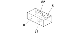
- FIG. 2 is a perspective view showing the appearance of the optical characteristic measuring device according to the embodiment of the present invention.
- the optical characteristic measuring device is configured to be a portable handy type.
- the lighting display device 1, the objective lens 2, the image sensor 3, and the calculation unit 4 are housed in the housing 8. Further, the upper surface of the housing 8 is provided with a gripping portion 82 for carrying, and the measurement result display unit 5 for displaying the measurement result is provided, and the lower surface of the housing 8 is covered with the sample 100. An opening 81 for irradiating the measurement portion 100a with illumination light and taking in the reflected light from the measurement portion is formed.
- the optical characteristic measuring device shown in FIG. 2 grips the grip portion 82 and positions the opening 81 on the lower surface at the measured portion 100a of the sample 100. Then, in this state, the sample 100 is irradiated with the illumination light from the illumination display device 1 housed inside the housing 8, the reflected light is received by the image pickup element 3, and the image data output from the image pickup element 3 is received. The optical characteristics are measured by the calculation unit 5 using the above, and the measurement result is displayed on the measurement result display unit 5.
- the optical characteristic can be measured regardless of the place by carrying the housing. (Embodiment 1) Next, the measurement of specific optical characteristics will be described.
- the optical characteristic is a characteristic at which reflection angle the illuminated portion 100a reflects the illumination light L1, and is evaluated in a specific analysis area among the total light receiving areas of the image pickup device 3 as described later.
- the optical property is information regarding the light distribution of the bright material (for example, the light distribution angle) will be described.
- a typical layer structure of a painted automobile surface containing a bright material is such that a bright material-containing layer 102 containing a bright material 110 is coated and laminated on a base layer 101 which is a base material. Further, a clear layer 103 made of a clear coat layer or the like is laminated on the clear layer 103.
- a clear layer 103 made of a clear coat layer or the like is laminated on the clear layer 103.
- the bright material 110 in the coating film exists in a state of having a certain inclination (orientation).
- the orientation distribution generally peaks in the horizontal direction (0 degree) of the coating film surface, and the number of bright materials decreases as the angle increases.
- the state of orientation depends on design factors such as the bright material 110 and the type of paint, and also on painting conditions such as paint spraying speed, pressure, and film thickness.
- the illumination light L1 When the illumination light L1 is incident on the measured portion 100a of the sample 100 having such a bright material-containing layer 102, a part of the illumination light L1 is specularly reflected (normally reflected) on the surface of the clear layer 103, and a part of the clear layer 103 is reflected. It penetrates the surface of. A part of the transmitted light is specularly reflected (specularly reflected light L12) by the bright material 110 inside the coating.
- the bright material reflection reflects light in a direction corresponding to the inclination of the bright material 110 from the horizontal direction of the coating film surface.
- the orientation angle ⁇ of many bright materials 110 is within 5 ° with respect to the sample normal direction. This corresponds to within
- ⁇ 15 ° in terms of the as angle in FIG. 2 when the refractive index of the clear layer is n 1.4 and the incident angle is 45 °.
- the spatial resolution of the image pickup device 3 is about 10 to 100 ⁇ m.
- the lighting display device 1 displays a predetermined lighting pattern and moves the displayed lighting pattern in one direction.
- a single bright spot can be mentioned as an example of a lighting pattern.
- FIG. 4A shows how this single bright point is displayed on the lighting display device 1 and moved
- FIG. 4B shows an image captured by the image sensor 3 when the bright point is moved. Shown in.
- the moving direction of the bright point 11 is a direction parallel to the surface composed of the normal of the measured portion 100a, the normal of the illumination display device 1, and the normal of the image pickup element 3 (FIG. 4 (A) lateral direction).
- the white portion of the rectangle is the bright point 11, and the black portion is the non-light emitting region.
- the lighting display device 1 has a rectangular display surface, and on the screen number A1, a bright point 11 is displayed at a vertical middle portion of one end portion in the horizontal direction (left end portion in FIG. 4A) of the display surface. ing. As shown by the arrow H1 on the screen A1, the bright point 11 moves (scans) in order to the other end side (right end side of FIG. 34A) in the lateral direction of the display surface.
- the screen numbers A1 ⁇ A2 ⁇ ... ⁇ An ⁇ ... indicate each display surface on which the bright point 11 is moving.
- the two-dimensional image pickup device 3 has a light receiving area having a rectangular shape as a whole, which is composed of a large number of pixels.
- the image number B1 shows an image captured by the image pickup element 3 when illuminated by the display screen of the screen number A1, and is one end in the lateral direction of the entire rectangular light receiving area (the left end in FIG. 4A).
- the white dots indicate that the light receiving portion 30 in the middle portion in the vertical direction has high brightness.
- the brightness of the light receiving unit 30 is high because the positive reflection component mirror-reflected on the surface of the clear layer 103 when the illumination light from the bright point 11 shown on the screen number A1 is applied to the measured portion 100a is received. Is. That is, the light receiving unit 30 is the point where the positive reflection component mirror-reflected on the surface of the clear layer 103 reaches the image element 3.
- the illumination angle with respect to the measured portion 100a changes sequentially, but the light is received.
- the angle of the image sensor 3 on the side is fixed. From the position of the bright point 11 and the geometry of the image sensor 3, the incident light direction and the emitted light direction at each measured portion 100a can be uniquely specified.
- the position of the light receiving portion 30 that receives the specular reflection component on the surface of the clear layer 103 when the illuminated portion 100a is irradiated with the illumination light from the moved bright point 11 is also the position of the image number B2 ⁇ ... ⁇ As shown in Bn ⁇ ..., the particles are sequentially moved to the other end side in the lateral direction (the right end side in FIG. 4B).
- the distance between the lighting display device 1 and the measured portion 100a of the measurement object 100 is 65.0 mm
- the lighting display device 1 is 2.4 inches QVGA
- the length of the long side is long.
- the illumination angle of the bright point 11 can be realized up to 21.8 ° in as angle. As described above, this is a sufficient illumination angle width for evaluating the bright material 110.
- the image pickup element 3 receives the specular reflected light of the bright material 110.
- the obtained brightness is maximized.
- FIGS. 6A to 6D These figures schematically show the state of reflection from the bright material 110 when the bright point 11 of the illumination display device 1 is moved in the width direction of the display surface. Further, each figure on the lower side shows a state in which the attention-grabbing material 111 is sandwiched between + marks and + marks.
- the bright point 11 does not move, the illumination angle with respect to the measured portion 100a is ⁇ 1, and in this state, the brightness of the bright material 110 having a downward-sloping inclination as shown in the attention bright material 111 is high. It will be the maximum.
- the bright point 11 moves and the illumination angle with respect to the measured portion 100a is ⁇ 2.
- the brightness of the bright material 110 arranged substantially horizontally is maximum as shown in the attention bright material 111.
- the bright point 11 further moves and the illumination angle with respect to the measured portion 100a is ⁇ 3. It becomes.
- FIG. 3D the bright point 11 further moves and the illumination angle with respect to the measured portion 100a is ⁇ 4. It will be the maximum.
- the angle at which the brightness is maximized differs for each pixel, and depends on the reflection angle of the glitter material 110 and thus the orientation angle. In other words, it is possible to estimate the orientation angle of each bright material from the peak position of the luminance.
- the specular reflection component on the surface of the clear layer 103 when the specular reflection component on the surface of the clear layer 103 is included, the peak of the luminance value appears at a position different from that derived from the bright material, so that it is difficult to estimate the optical characteristics derived from the bright material. Become.
- a specific area in the light receiving area of the image pickup device 3 that does not receive specular reflection component on the surface of the clear layer 103 is set as an analysis area, and a bright material is used based on the light receiving result in this analysis area.
- the optical characteristics of 110 are analyzed.
- the rectangular area 31 of the broken line and the rectangular area 32 of the solid line are tentatively set in the total light receiving area of the image sensor 3.
- the position where the specular reflection component on the surface of the surface reaches the image sensor 3 side also moves in the lateral direction, but the broken line rectangular area 31 is located on the line in the moving direction (corresponding to the first direction) of the light receiving unit 30.
- the specular reflection component on the surface of the clear layer 103 is received.
- the solid rectangular area 32 is located at a position vertically deviated from the moving direction of the light receiving portion 30 accompanying the movement of the bright point 11, and even if the bright point 11 moves, the surface of the clear layer 103 by each bright point 11 It does not receive any specular reflection component in.
- the analysis area is a solid rectangular area 32 that receives only the specularly reflected light derived from the bright material and does not receive the specular reflection component on the surface of the clear layer 103, and analyzes the light receiving results of the pixels in the analysis area 32.
- the optical characteristics of the bright material 110 are obtained.
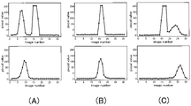
- each of the 31 images captured at the position of each bright point 11 is an image ( Image-number) 1 to image 31, an example of the brightness value obtained for each 31 images for each pixel in the solid line rectangular area (analysis area) 32 and the broken line rectangular area 31 is shown in the figure. 7 (A) (B) (C).
- the upper graph of the figure is the pixel value for the pixel in the broken line rectangular area 31, and the lower graph is the pixel value for the pixel (the pixel of interest) in the solid line rectangular area 32, and the horizontal axis of each graph. Is the image number and the vertical axis is the brightness value.
- the luminance value is held at 8 bits, the maximum value is 255, and the minimum value is 0.
- FIGS. 7A, 7B, and 7C show a case where the peaks of the specularly reflected light of the bright material 110 are present in the first half image, the image near the center, and the second half image, respectively.
- a peak always exists near the image number 15 in any of (A) to (C). This is the peak of the specular reflection component on the surface of the clear layer 103. Due to this peak, it is difficult to directly associate the peak position with the orientation of the bright material 110.
- the luminance component derived from the bright material having a peak near the image number 15 is buried in the specular reflection component on the surface of the clear layer 103 as shown in the upper graph of FIG. 7B, and thus is derived from the bright material. It is difficult to detect the peak of the luminance component itself. Further, the reflection of the bright material showing a peak at this position is due to the bright material 110 having a small inclination, and usually such a thing is often used from the orientation distribution of the bright material 110.
- the orientation information of the bright material 110 can be calculated from the peak position. That is, it is possible to calculate highly accurate light distribution information based on the luminance setting of the pixels in the solid line rectangular area (analysis area) 32.
- the horizontal direction of the measured portion 100a is the x direction
- the vertical direction is the y direction
- the inclination in the y direction is ⁇ x with the x direction of the bright material 110 as the central axis
- the inclination in the y direction is the x direction with the y direction as the central axis. It is assumed that the inclination is ⁇ y and the bright point 11 of the illumination display device 1 is moved in the x direction.
- ⁇ x' is an angle uniquely determined from the amount of deviation from the moving direction line of the analysis area 32 for analyzing the specularly reflected light by the bright material 110 of the moving bright point 11 and the geometry of the image pickup device 3.
- ⁇ y' corresponds to the peak position obtained by the above measurement.
- the exterior of an automobile or the like has a surface structure as shown in FIG. 2, and the illumination light incident on the measured portion 100a of the object to be measured 100 is refracted on the surface of the clear layer 103.
- accurate orientation information of the bright material 110 can be calculated from the above information.
- the peak of the luminance value obtained in the analysis area 32 does not include the specular reflection component on the surface of the clear layer 103, and is purely derived from the reflection of the bright material 110. Luminance information of the bright material 110 can be calculated from the peak value.
- the pixels other than the pixel of interest do not include the specular reflection component due to the clear layer 200. Therefore, by performing the same analysis for the entire analysis area, statistical information such as the luminance distribution and the orientation distribution can be obtained. can do.
- the measured portion 100a of the object to be measured 100 is illuminated by the illumination light whose illumination angle is changed to a plurality by moving and scanning the bright point 11 in one direction, and the image pickup element 3 is used.
- the analysis area 32 a specific area in which no positive reflection component is received on the surface of the clear layer 103 of each illumination light whose illumination angle is changed is set as the analysis area 32, and the normal reflection by the bright material 110 in the analysis area 32 is defined as the analysis area 32.
- the optical characteristics of the bright material 110 are analyzed based on the light receiving result of only light. Therefore, the optical characteristics such as the brightness and the light distribution characteristics of the bright material 110 can be accurately measured by eliminating the influence of the specular reflection component on the surface of the clear layer 103.
- optical characteristics that can be obtained in this embodiment are not limited to luminance and orientation information.
- FIG. 9A shows a case where a large number of bright materials 110 having a small particle size are present
- FIG. 9B shows a case where a large number of bright materials 110 having a large particle size are present.
- the particle size of the bright material 110 can be calculated from the fact that the light distribution angle and the length in the horizontal direction of the bright material 110 can be known by analyzing the two-dimensional spatial luminance distribution.
- FIG. 10A shows a state in which the bright material 110 is dispersed
- FIG. 10B shows a state in which the bright material 110 is aggregated.
- the moving direction of the bright point 11 is set in the vertical direction of FIG. 4A, that is, the normal of the measured portion 100a, the normal of the illumination display device 1, and the normal of the image sensor 3.
- the direction may be perpendicular to the surface to be constructed.
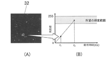
- the appropriate exposure time differs for each measurement object 100. From the viewpoint of shortening the overall measurement time, it is desirable to first perform preliminary measurement for determining the exposure time, and then perform a series of main measurements with the optimum exposure time calculated using the acquired information.
- the exposure time is long, but from the viewpoint of luminance value calculation and luminance change analysis, it is necessary not to exceed the measured maximum luminance value. Therefore, it is desirable to select an exposure time in which the luminance value of the bright spot of the bright material 110 when the illumination light is specularly reflected is within a desired luminance range.
- the analysis area 32 actually used in this measurement is used, and the illumination pattern (for example, bright point) actually used in this measurement is used. It is desirable that the illumination pattern illuminates a portion close to the analysis area 32, but this is not the case.
- an image is taken at a preset short time t1.
- the luminance values of those that are characteristically bright as shown in FIG. 11A are used.
- the characteristically bright one the one having the highest luminance value in the analysis area 32 may be used, but this is not the case.
- the exposure time t2 is used as a reference, and the measurement is performed with the exposure time suitable for each lighting.
- the exposure time for the image pickup element 3 is determined for each illumination angle of the illumination light before the start of the measurement, it is possible to measure the optical characteristics with higher accuracy with an appropriate exposure time. can.
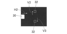
- the analysis areas 32 and 32 in the image pickup device 3 are provided on both sides of the light receiving portion 30 of the specular reflection component on the surface of the clear layer 103 with respect to the movement direction H. It is set at a position deviated from V2 and V3 in the vertical direction, respectively.
- the light receiving unit 30 passes through the midpoints of the analysis areas 32 and 32. The positions of both analysis areas 32 and 32 do not have to be the same in each captured image when the bright point 11 is moved.
- the analysis area 32 is increased, the illumination / light receiving angle width becomes large. Therefore, it is better that the analysis area 32 is small. On the other hand, if the analysis area 32 is not sufficiently secured, the statistical information of the glitter material 110 will be obtained. From this point of view, it is better that the analysis area 32 is large because it cannot be acquired.
- the trade-off relationship can be solved at the same time.
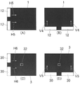
- vertically long bright lines 12 and 12 are displayed at both ends of the rectangular display surface of the lighting display device 1 except for the intermediate portion in the vertical direction, and these bright lines 12 and 12 are displayed.
- the illumination angle of the illumination light with respect to the measured portion 100a is changed by moving and scanning in the lateral direction.
- both ends of the entire rectangular light receiving area excluding the intermediate portion in the vertical direction are clear layers of the illumination light of the bright lines 12 and 12. It is a light receiving unit 30 that receives a specular reflection component on the surface of 103. Then, according to the lateral movement (scanning) of the bright lines 12, 12, the two light receiving portions 30, 30 move in the lateral directions (corresponding to the second and third directions) H4, H4.
- the analysis area 32 is set at a position intermediate between the two moving directions H4 and H4 of the two light receiving units 30 and 30 in the light receiving area of the image sensor 30 and substantially in the center in the lateral direction. ..
- the specular reflection component on the surface of the clear layer 103 is not received, and only the specular reflection light derived from the bright material is received. Therefore, as in the case of the bright point 11, the brightness of the bright material 110 is increased.
- Optical characteristics such as orientation characteristics can be measured.
- two bright points may be used instead of the two bright lines 12 and 12.
- the two bright lines 12 and 12 used in the fourth embodiment are moved in the horizontal direction (x direction) and the vertical direction (y direction) of the display surface of the lighting display device 1, respectively.
- vertically long bright lines 12 and 12 are displayed at both ends of the rectangular display surface of the lighting display device 1 except for the intermediate portion in the vertical direction, and these bright lines 12 are displayed. , 12 are moved laterally as shown by arrows H5 and H5 to change the illumination angle of the illumination light with respect to the measured portion 100a.
- horizontally long bright lines 12 and 12 are displayed at both ends of the rectangular display surface of the lighting display device 1 except for the intermediate portion in the horizontal direction at the lower end of the rectangular display surface, and these bright lines 12 and 12 are displayed.
- the illumination angle of the illumination light with respect to the measured portion 100a is changed.
- FIG. 14 (C) The image of the image pickup device 3 corresponding to the bright lines 12 and 12 shown in FIG. 14 (A) is shown in FIG. 14 (C).
- both ends of the entire rectangular light receiving area except the middle part in the vertical direction receive the specular reflection component on the surface of the clear layer 103 of the illumination light by the bright lines 12 and 12, and the light receiving parts 30 and 30.
- the two light receiving portions 30 and 30 move laterally as indicated by the arrows H6 and H6.
- FIG. 14 (D) The image of the image pickup device 3 corresponding to the bright lines 12 and 12 shown in FIG. 14 (B) is shown in FIG. 14 (D).
- both ends of the entire rectangular light receiving area except the middle part in the lateral direction receive the specular reflection component on the surface of the clear layer 103 of the illumination light by the bright lines 12 and 12, and the light receiving parts 30 and 30.
- the two light receiving portions 30 and 30 move in the vertical direction as indicated by the arrows V5 and V6.
- the central portion of the light receiving area 30 of the specular reflection component on the surface of the clear layer does not pass through.
- the analysis area 32 is set in. In this analysis area 32, the specular reflection component on the surface of the clear layer 103 is not received, and only the specular reflection light derived from the bright material is received. Therefore, the optical characteristics such as the brightness and orientation characteristics of the bright material 110 are measured. be able to.
- the two bright points may be moved in the vertical direction and the horizontal direction instead of the two bright lines 12 and 12.
- (Modification example) Although each embodiment of the present invention has been described above, the present invention is not limited to the above embodiment.
- the lighting device is configured by the lighting display device 1 for moving the lighting pattern composed of the bright points 11 and the bright lines 12 on the screen has been described, but one point light source or the line light source may be moved.
- the lighting device may be configured to change the illumination angle of the illumination light by arranging a plurality of point light sources or line light sources and sequentially controlling the lighting.
- the image pickup element 3 is not a two-dimensional image pickup element, and a line sensor or the like arranged so that at least one or a plurality of pixels are located on the analysis area 32 may be used.
- the sample 100 in which the surface is coated with the bright material 110 is exemplified, even when the bright material 110 is not contained, when a treatment such as an alumite treatment is applied, the surface has minute irregularities. And the gradient exists in the micro region on the order of several ⁇ m to several tens of ⁇ m. Due to its microstructure, a part of the surface looks shining when illuminated and observed from a specific direction, and another part shines when illuminated and observed from another direction, which is a driving force for expressing high design. .. Therefore, even if the bright material 110 does not exist, it is possible to similarly measure the optical characteristics of the sample 100 having a fine unevenness or gradient on the surface, such as the one treated with alumite.
- the present invention can be used as an optical characteristic measuring device for measuring the optical characteristics of a coated portion including flaky aluminum pieces or mica pieces called a bright material as a measured portion.
Landscapes
- Physics & Mathematics (AREA)
- Health & Medical Sciences (AREA)
- Life Sciences & Earth Sciences (AREA)
- Chemical & Material Sciences (AREA)
- Analytical Chemistry (AREA)
- Biochemistry (AREA)
- General Health & Medical Sciences (AREA)
- General Physics & Mathematics (AREA)
- Immunology (AREA)
- Pathology (AREA)
- Mathematical Physics (AREA)
- Investigating Or Analysing Materials By Optical Means (AREA)
Priority Applications (2)
| Application Number | Priority Date | Filing Date | Title |
|---|---|---|---|
| EP21872169.4A EP4220135B1 (en) | 2020-09-25 | 2021-09-09 | Optical characteristics measuring device, and optical characteristics measuring method |
| JP2022551858A JP7632472B2 (ja) | 2020-09-25 | 2021-09-09 | 光学特性測定装置及び光学特性測定方法 |
Applications Claiming Priority (2)
| Application Number | Priority Date | Filing Date | Title |
|---|---|---|---|
| JP2020160338 | 2020-09-25 | ||
| JP2020-160338 | 2020-09-25 |
Publications (1)
| Publication Number | Publication Date |
|---|---|
| WO2022065038A1 true WO2022065038A1 (ja) | 2022-03-31 |
Family
ID=80845195
Family Applications (1)
| Application Number | Title | Priority Date | Filing Date |
|---|---|---|---|
| PCT/JP2021/033073 Ceased WO2022065038A1 (ja) | 2020-09-25 | 2021-09-09 | 光学特性測定装置及び光学特性測定方法 |
Country Status (3)
| Country | Link |
|---|---|
| EP (1) | EP4220135B1 (https=) |
| JP (1) | JP7632472B2 (https=) |
| WO (1) | WO2022065038A1 (https=) |
Citations (9)
| Publication number | Priority date | Publication date | Assignee | Title |
|---|---|---|---|---|
| JPH0755705A (ja) * | 1993-08-09 | 1995-03-03 | Toyota Motor Corp | 塗装深み感の評価方法 |
| JP2003075257A (ja) * | 2001-09-04 | 2003-03-12 | Minolta Co Ltd | 反射特性測定装置 |
| JP2008523521A (ja) * | 2004-12-14 | 2008-07-03 | アクゾ ノーベル コーティングス インターナショナル ビー ヴィ | 表面の外観特性の解析方法および解析装置 |
| WO2014134099A1 (en) * | 2013-02-26 | 2014-09-04 | Axalta Coating Systems IP Co. LLC | Process for matching color and appearance of coatings |
| JP2014240830A (ja) | 2013-05-15 | 2014-12-25 | キヤノン株式会社 | 測定装置およびその制御方法 |
| JP2018009987A (ja) | 2016-07-04 | 2018-01-18 | 株式会社リコー | 計測システム、反射率計算方法及びプログラム |
| WO2020054381A1 (ja) * | 2018-09-14 | 2020-03-19 | コニカミノルタ株式会社 | 表面特性測定用データの出力装置及び表面特性測定装置 |
| WO2020145023A1 (ja) * | 2019-01-10 | 2020-07-16 | コニカミノルタ株式会社 | 光学特性解析装置及びプログラム |
| JP2020160338A (ja) | 2019-03-27 | 2020-10-01 | 太陽ホールディングス株式会社 | 感光性樹脂組成物、ドライフィルム、硬化物、及び、電子部品 |
Family Cites Families (4)
| Publication number | Priority date | Publication date | Assignee | Title |
|---|---|---|---|---|
| JPH11211673A (ja) * | 1998-01-27 | 1999-08-06 | Honda Motor Co Ltd | 表面性状評価装置および表面性状評価方法 |
| JP5073996B2 (ja) * | 2006-09-20 | 2012-11-14 | オリンパス株式会社 | 画像処理装置 |
| WO2011101893A1 (ja) * | 2010-02-17 | 2011-08-25 | コニカミノルタホールディングス株式会社 | 可撓性を有する検査対象物の表面の傷を検査する方法および装置 |
| US11025800B2 (en) | 2018-04-13 | 2021-06-01 | Arius Technology Inc. | Systems and methods for imaging fine art paintings |
-
2021
- 2021-09-09 JP JP2022551858A patent/JP7632472B2/ja active Active
- 2021-09-09 EP EP21872169.4A patent/EP4220135B1/en active Active
- 2021-09-09 WO PCT/JP2021/033073 patent/WO2022065038A1/ja not_active Ceased
Patent Citations (9)
| Publication number | Priority date | Publication date | Assignee | Title |
|---|---|---|---|---|
| JPH0755705A (ja) * | 1993-08-09 | 1995-03-03 | Toyota Motor Corp | 塗装深み感の評価方法 |
| JP2003075257A (ja) * | 2001-09-04 | 2003-03-12 | Minolta Co Ltd | 反射特性測定装置 |
| JP2008523521A (ja) * | 2004-12-14 | 2008-07-03 | アクゾ ノーベル コーティングス インターナショナル ビー ヴィ | 表面の外観特性の解析方法および解析装置 |
| WO2014134099A1 (en) * | 2013-02-26 | 2014-09-04 | Axalta Coating Systems IP Co. LLC | Process for matching color and appearance of coatings |
| JP2014240830A (ja) | 2013-05-15 | 2014-12-25 | キヤノン株式会社 | 測定装置およびその制御方法 |
| JP2018009987A (ja) | 2016-07-04 | 2018-01-18 | 株式会社リコー | 計測システム、反射率計算方法及びプログラム |
| WO2020054381A1 (ja) * | 2018-09-14 | 2020-03-19 | コニカミノルタ株式会社 | 表面特性測定用データの出力装置及び表面特性測定装置 |
| WO2020145023A1 (ja) * | 2019-01-10 | 2020-07-16 | コニカミノルタ株式会社 | 光学特性解析装置及びプログラム |
| JP2020160338A (ja) | 2019-03-27 | 2020-10-01 | 太陽ホールディングス株式会社 | 感光性樹脂組成物、ドライフィルム、硬化物、及び、電子部品 |
Non-Patent Citations (1)
| Title |
|---|
| See also references of EP4220135A4 |
Also Published As
| Publication number | Publication date |
|---|---|
| JPWO2022065038A1 (https=) | 2022-03-31 |
| EP4220135A1 (en) | 2023-08-02 |
| EP4220135A4 (en) | 2024-03-06 |
| JP7632472B2 (ja) | 2025-02-19 |
| EP4220135B1 (en) | 2025-07-23 |
Similar Documents
| Publication | Publication Date | Title |
|---|---|---|
| KR101894683B1 (ko) | 금속체의 형상 검사 장치 및 금속체의 형상 검사 방법 | |
| JP6942876B2 (ja) | 情報処理装置、情報処理方法およびプログラム | |
| CA2507642C (en) | Method and device for optical shape measurement and/or evaluation | |
| US8355141B2 (en) | Device for the investigation of textured surfaces | |
| US20170205291A1 (en) | Measurement system, information processing apparatus, information processing method, and medium | |
| AU2005252721B2 (en) | Appliance for controlling transparent or reflective elements | |
| JPH11211673A (ja) | 表面性状評価装置および表面性状評価方法 | |
| JP2011075544A (ja) | 肌理のある面の特性を決定するための方法および装置 | |
| CN105277558A (zh) | 一种研究表面的多步方法及其对应设备 | |
| JP2004354381A (ja) | 表面特性を特定する装置および方法 | |
| CN117309868A (zh) | 表面检查系统 | |
| JP2009168454A (ja) | 表面欠陥検査装置及び表面欠陥検査方法 | |
| TW201925746A (zh) | 缺陷檢查裝置及缺陷檢查方法 | |
| JPWO2020054381A1 (ja) | 表面特性測定用データの出力装置及び表面特性測定装置 | |
| CN100340840C (zh) | 光学形状测量或评定的方法及装置 | |
| WO2022065038A1 (ja) | 光学特性測定装置及び光学特性測定方法 | |
| JP6013819B2 (ja) | 表面形状検査装置及び表面形状検査方法 | |
| JP2007078517A (ja) | 表面平滑性測定装置 | |
| Ritz et al. | High resolution acquisition of detailed surfaces with lens-shifted structured light | |
| WO2020145023A1 (ja) | 光学特性解析装置及びプログラム | |
| RU2439489C1 (ru) | Способ бесконтактного измерения геометрии трехмерных объектов | |
| Filip et al. | Waviness analysis of glossy surfaces based on deformation of a light source reflection | |
| JPWO2020054382A1 (ja) | 表面特性測定用データの出力装置及び表面特性測定装置 | |
| JP2008224540A (ja) | 歪み検査方法および検査装置 | |
| Becker et al. | 29‐4: image blurring induced by scattering anti‐glare layers |
Legal Events
| Date | Code | Title | Description |
|---|---|---|---|
| 121 | Ep: the epo has been informed by wipo that ep was designated in this application |
Ref document number: 21872169 Country of ref document: EP Kind code of ref document: A1 |
|
| ENP | Entry into the national phase |
Ref document number: 2022551858 Country of ref document: JP Kind code of ref document: A |
|
| NENP | Non-entry into the national phase |
Ref country code: DE |
|
| ENP | Entry into the national phase |
Ref document number: 2021872169 Country of ref document: EP Effective date: 20230425 |
|
| WWG | Wipo information: grant in national office |
Ref document number: 2021872169 Country of ref document: EP |