WO2022065023A1 - Ferrule et connecteur optique - Google Patents
Ferrule et connecteur optique Download PDFInfo
- Publication number
- WO2022065023A1 WO2022065023A1 PCT/JP2021/032822 JP2021032822W WO2022065023A1 WO 2022065023 A1 WO2022065023 A1 WO 2022065023A1 JP 2021032822 W JP2021032822 W JP 2021032822W WO 2022065023 A1 WO2022065023 A1 WO 2022065023A1
- Authority
- WO
- WIPO (PCT)
- Prior art keywords
- fiber
- groove portion
- fiber groove
- ferrule
- optical
- Prior art date
Links
Images


Classifications
-
- G—PHYSICS
- G02—OPTICS
- G02B—OPTICAL ELEMENTS, SYSTEMS OR APPARATUS
- G02B6/00—Light guides; Structural details of arrangements comprising light guides and other optical elements, e.g. couplings
- G02B6/24—Coupling light guides
- G02B6/36—Mechanical coupling means
- G02B6/38—Mechanical coupling means having fibre to fibre mating means
- G02B6/3807—Dismountable connectors, i.e. comprising plugs
- G02B6/3833—Details of mounting fibres in ferrules; Assembly methods; Manufacture
- G02B6/3834—Means for centering or aligning the light guide within the ferrule
- G02B6/3838—Means for centering or aligning the light guide within the ferrule using grooves for light guides
- G02B6/3839—Means for centering or aligning the light guide within the ferrule using grooves for light guides for a plurality of light guides
-
- G—PHYSICS
- G02—OPTICS
- G02B—OPTICAL ELEMENTS, SYSTEMS OR APPARATUS
- G02B6/00—Light guides; Structural details of arrangements comprising light guides and other optical elements, e.g. couplings
- G02B6/24—Coupling light guides
- G02B6/36—Mechanical coupling means
- G02B6/38—Mechanical coupling means having fibre to fibre mating means
- G02B6/3807—Dismountable connectors, i.e. comprising plugs
- G02B6/3873—Connectors using guide surfaces for aligning ferrule ends, e.g. tubes, sleeves, V-grooves, rods, pins, balls
- G02B6/3885—Multicore or multichannel optical connectors, i.e. one single ferrule containing more than one fibre, e.g. ribbon type
-
- G—PHYSICS
- G02—OPTICS
- G02B—OPTICAL ELEMENTS, SYSTEMS OR APPARATUS
- G02B6/00—Light guides; Structural details of arrangements comprising light guides and other optical elements, e.g. couplings
- G02B6/24—Coupling light guides
- G02B6/36—Mechanical coupling means
- G02B6/38—Mechanical coupling means having fibre to fibre mating means
- G02B6/3807—Dismountable connectors, i.e. comprising plugs
- G02B6/3833—Details of mounting fibres in ferrules; Assembly methods; Manufacture
- G02B6/3834—Means for centering or aligning the light guide within the ferrule
- G02B6/3838—Means for centering or aligning the light guide within the ferrule using grooves for light guides
-
- G—PHYSICS
- G02—OPTICS
- G02B—OPTICAL ELEMENTS, SYSTEMS OR APPARATUS
- G02B6/00—Light guides; Structural details of arrangements comprising light guides and other optical elements, e.g. couplings
- G02B6/24—Coupling light guides
- G02B6/36—Mechanical coupling means
- G02B6/38—Mechanical coupling means having fibre to fibre mating means
- G02B6/3807—Dismountable connectors, i.e. comprising plugs
- G02B6/3833—Details of mounting fibres in ferrules; Assembly methods; Manufacture
- G02B6/3853—Lens inside the ferrule
-
- G—PHYSICS
- G02—OPTICS
- G02B—OPTICAL ELEMENTS, SYSTEMS OR APPARATUS
- G02B6/00—Light guides; Structural details of arrangements comprising light guides and other optical elements, e.g. couplings
- G02B6/24—Coupling light guides
- G02B6/36—Mechanical coupling means
- G02B6/38—Mechanical coupling means having fibre to fibre mating means
- G02B6/3807—Dismountable connectors, i.e. comprising plugs
- G02B6/3873—Connectors using guide surfaces for aligning ferrule ends, e.g. tubes, sleeves, V-grooves, rods, pins, balls
- G02B6/3881—Connectors using guide surfaces for aligning ferrule ends, e.g. tubes, sleeves, V-grooves, rods, pins, balls using grooves to align ferrule ends
Definitions
- the present disclosure relates to ferrules and optical connectors.
- This application claims priority based on Japanese Application No. 2020-161209 filed on September 25, 2020, and incorporates all the contents described in the Japanese application.
- an optical connector including a ferrule having a plurality of lenses at the tip portion and a plurality of optical fibers inserted inside the ferrule is known (see, for example, Patent Document 1).
- a plurality of fiber grooves for supporting the plurality of optical fibers are provided at positions corresponding to the plurality of lenses.
- the ferrule according to the embodiment of the present disclosure is a first aspect between the tip surface, an opening provided on the side opposite to the tip surface in the first direction intersecting the tip surface, and the tip surface and the opening.
- a plurality of fiber grooves extending along a direction and arranged along a second direction intersecting the first direction, each capable of supporting a plurality of optical fibers, and an extension line of the plurality of fiber grooves, respectively. It is equipped with multiple lenses.
- the fiber groove has a first fiber groove portion for positioning the optical fiber with respect to the lens, and a second fiber groove portion for introducing the optical fiber into the first fiber groove portion.
- the first fiber groove portion is arranged closer to the lens than the second fiber groove portion in the first direction.
- the optical connector according to the embodiment of the present disclosure includes the above-mentioned ferrule and a plurality of optical fibers supported by a plurality of fiber grooves and arranged on the optical axes of the plurality of lenses.
- FIG. 1 is a perspective view showing an optical connector according to an embodiment.
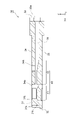
- FIG. 2 is a cross-sectional view showing the optical connector of FIG.
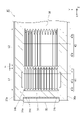
- FIG. 3 is a perspective view showing a ferrule according to an embodiment.
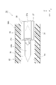
- FIG. 4 is a cross-sectional view showing the ferrule of FIG.
- FIG. 5 is an enlarged cross-sectional view of a part of the ferrule of FIG.
- FIG. 6 is another cross-sectional view showing the ferrule of FIG.
- FIG. 7A is a cross-sectional view showing a straight portion of the first fiber groove portion.
- FIG. 7B is a cross-sectional view showing a straight portion of the second fiber groove portion.
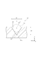
- FIG. 8 is a cross-sectional view showing a tapered portion of the second fiber groove portion.
- FIG. 9A is a cross-sectional view showing a modified example of the shape of the second fiber groove portion.
- FIG. 9B is a cross-sectional view showing another modification of the shape of the second fiber groove portion.
- FIG. 9C is a cross-sectional view showing another modification of the shape of the second fiber groove portion.
- FIG. 10 is a perspective view showing an optical connection structure including an optical connector.
- 11 is a plan view showing the optical connection structure of FIG. 10.
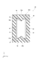
- FIG. FIG. 12 is a rear view showing the optical connection structure of FIG.
- FIG. 13 is a rear view showing a modified example of the adapter having an optical connection structure.
- FIG. 14 is a diagram showing how the optical connector is inserted into the adapter of FIG.
- the ferrule according to the embodiment of the present disclosure is a first aspect between the tip surface, an opening provided on the side opposite to the tip surface in the first direction intersecting the tip surface, and the tip surface and the opening.
- a plurality of fiber grooves extending along a direction and arranged along a second direction intersecting the first direction, each capable of supporting a plurality of optical fibers, and an extension line of the plurality of fiber grooves, respectively. It is equipped with multiple lenses.
- the fiber groove has a first fiber groove portion for positioning the optical fiber with respect to the lens, and a second fiber groove portion for introducing the optical fiber into the first fiber groove portion.
- the first fiber groove portion is arranged closer to the lens than the second fiber groove portion in the first direction.
- the fiber groove of this ferrule has a second fiber groove for introducing an optical fiber into the first fiber groove in addition to the first fiber groove for positioning the optical fiber with respect to the lens.
- the first fiber groove portion is arranged closer to the lens than the second fiber groove portion in the first direction. Therefore, when the optical fiber is inserted into the ferrule through the opening, the optical fiber is introduced into the first fiber groove by the second fiber groove, and the optical fiber is positioned with respect to the lens in the first fiber groove.
- the existence of the second fiber groove portion for introducing the optical fiber into the first fiber groove portion causes the optical fiber to collide with the wall portion between the fiber grooves when the optical fiber is inserted inside the ferrule. This can be reduced and the optical fiber can be reliably arranged in the first fiber groove portion. Therefore, according to the above-mentioned ferrule, workability when assembling the optical fiber can be improved.
- each of the first fiber groove portion and the second fiber groove portion may have a V shape. In this case, the position of the optical fiber with respect to the lens can be positioned more accurately.
- the opening width of the second fiber groove portion may be larger than the opening width of the first fiber groove portion.
- the allowable amount of deviation of the optical fiber supported by the second fiber groove with respect to the lens should be larger than the allowable amount of deviation of the optical fiber supported by the first fiber groove with respect to the lens.
- the diameter of the virtual circle centered on the optical axis of the lens and inscribed in the second fiber groove is larger than the diameter of the virtual circle centered on the optical axis of the lens and inscribed in the first fiber groove. May be large.
- the allowable amount of deviation of the optical fiber supported by the second fiber groove with respect to the lens should be larger than the allowable amount of deviation of the optical fiber supported by the first fiber groove with respect to the lens. Can be done.
- the position of the optical fiber with respect to the lens is determined in the second fiber groove, and then the position of the optical fiber with respect to the lens is determined in the first fiber groove with high accuracy. Can be done.
- the second fiber groove portion has a straight portion having a constant diameter of a virtual circle inscribed in the second fiber groove portion and centered on the optical axis of the lens at each position along the first direction, and a straight portion in the first direction.
- a tapered portion which is arranged on the opposite side of the first fiber groove portion and is inclined so that the diameter of the virtual circle inscribed in the second fiber groove portion becomes larger with respect to the optical axis of the lens as the distance from the straight portion increases. May include. The presence of such a tapered portion allows the optical fiber inserted into the inside of the ferrule from the opening to be reliably attracted to the straight portion.
- the presence of the straight portion enables the posture of the optical fiber to be stabilized along the first direction, and the optical fiber can be smoothly introduced into the first fiber groove portion with the posture stabilized. can. Therefore, according to the above-described configuration, the optical fiber can be reliably and smoothly introduced into the first fiber groove portion.
- the total length of the second fiber groove portion in the first direction may be equal to or greater than the total length of the first fiber groove portion in the first direction. In this case, the posture of the optical fiber can be more reliably stabilized in the second fiber groove portion.
- the second fiber groove may be arranged at a predetermined distance from the first fiber groove.
- the first fiber groove portion can be manufactured with high accuracy.
- an upper surface arranged at a position facing a plurality of fiber grooves in a third direction intersecting the first direction and the second direction may be further provided.
- the upper surface may have a window portion that opens in a region facing the first fiber groove portion in the third direction.
- the first fiber groove portion may be contained inside the window portion.
- the window portion can be used not only as an injection window portion for injecting an adhesive into the ferrule, but also for an alignment operation when introducing an optical fiber into the first fiber groove portion. This makes it possible to further improve workability when assembling the optical fiber.
- the above-mentioned ferrule may further include a pair of side surfaces arranged at positions facing each other across a plurality of fiber grooves in the second direction.
- a guide portion for guiding insertion into the adapter along the first direction may be provided on each of the pair of side surfaces.
- the guide portions provided on the pair of side surfaces can be used for positioning the ferrule with respect to the adapter. This makes it possible to position the ferrule with respect to the adapter without using expensive guide pins.
- the optical connector according to the embodiment of the present disclosure includes any of the above-mentioned ferrules and a plurality of optical fibers supported by a plurality of fiber grooves and arranged on the optical axes of the plurality of lenses. Since this optical connector includes any of the above-mentioned ferrules, workability when assembling the optical fiber to the ferrule can be improved as described above.
- the optical fiber may be fixed to the first fiber groove portion by an adhesive.
- the positioning of the optical fiber with respect to the lens can be performed more reliably.
- the ferrule has an upper surface arranged at a position facing a plurality of fiber grooves in a third direction intersecting the first direction and the second direction, and the upper surface has a first fiber groove portion and a third direction. It may have a window portion that opens in a region facing the light. Inside the window portion, a lid portion arranged on the first fiber groove portion via an optical fiber may be provided. In this case, the lid portion presses the optical fiber against the first fiber groove portion, so that the positioning of the optical fiber with respect to the lens can be performed more reliably.
- FIG. 1 is a perspective view showing an optical connector 10 according to this embodiment.
- FIG. 2 is a cross-sectional view showing the optical connector 10.
- Each figure shows an XYZ Cartesian coordinate system for ease of understanding.
- the longitudinal direction of the optical connector 10 is the X direction (first direction)
- the lateral direction of the optical connector 10 is the Y direction (second direction)
- the height direction of the optical connector 10 is the Z direction (first direction). 3 directions).
- the explanation may be given by defining the directions as "front” and "rear”. Of the X directions, the direction from the optical connector 10 toward the optical connector 10 (see FIG. 10) of the connection partner is defined as "front”, and the opposite direction is defined as "rear”.
- the optical connector 10 includes a plurality of (12 in this embodiment) optical fibers 20 and a ferrule 30 into which a front end portion of the plurality of optical fibers 20 is inserted.
- Each optical fiber 20 extends along the X direction and is arranged in a row along the Y direction.
- Each optical fiber 20 may be a multimode optical fiber (MMF: Multi-ModeFiber) or a single mode optical fiber (SMF: Single-ModeFiber).
- MMF Multi-ModeFiber
- SMF Single-ModeFiber
- the number of the optical fibers 20 is not limited to 12, and may be another number such as, for example, 4, 8, or 16.
- the ferrule 30 holds a plurality of optical fibers 20.
- the ferrule 30 has, for example, a substantially rectangular parallelepiped appearance.
- the ferrule 30 has a lens portion 31 at its front end.
- the ferrule 30 is integrally configured with, for example, the lens unit 31. That is, the ferrule 30 is integrally molded with the lens portion 31. Therefore, the ferrule 30 is made of the same material as the lens portion 31, that is, a light-transmitting material that can form the lens portion 31.
- the ferrule 30 is composed of, for example, PPS (polyphenylene sulfide), PEI (polyetherimide), PC (polycarbonate), PMMA (polymethylmethacrylate), PES (polyethersulphon), COP (cycloolefin polymer), or the like. Can be.
- PPS polyphenylene sulfide
- PEI polyetherimide
- PC polycarbonate
- PMMA polymethylmethacrylate
- PES polyethersulphon
- COP cycloolefin polymer
- the lens unit 31 is provided in front of the plurality of optical fibers 20 and faces the plurality of optical fibers 20 in the X direction.
- the lens portion 31 has, for example, a plate shape along the YZ plane.
- the lens unit 31 includes a front end surface 31a located at the front end in the X direction, a rear end surface 31b located at the rear end in the X direction, and a plurality of lenses 31c provided on the front end surface 31a.
- the front end surface 31a and the rear end surface 31b are, for example, planes parallel to the YZ plane.
- the rear end surface 31b faces a plurality of optical fibers 20 in the X direction.
- Each lens 31c is a convex lens that protrudes forward from the front end surface 31a.
- the lenses 31c are arranged in a row along the Y direction so as to correspond to the positions of the optical fibers 20.
- Each lens 31c is arranged on the optical axis of each optical fiber 20 and is optically coupled to each optical fiber 20. For example, when viewed from the X direction, the optical axis of each lens 31c coincides with the optical axis of each optical fiber 20.
- the light emitted from each optical fiber 20 is converted into parallel light (that is, collimated light) by each lens 31c, and then incident on the optical connector 10 (see FIG. 10) of the connection partner.
- the optical axis of the optical fiber 20 and the optical axis of the lens 31c may be deviated from each other.
- the front end surface of the optical fiber 20 or the front end surface 31a of the lens portion 31 may be inclined by, for example, 8 ° with respect to the YZ plane.
- the ferrule 30 has four outer surfaces that connect the front end surface 32 (tip surface) located at the front end in the X direction, the rear end surface 33 located at the rear end in the X direction, and the front end surface 32 and the rear end surface 33 in the X direction. It has sides 34, 35, 36, and 37.
- the front end surface 32 and the rear end surface 33 are, for example, along the YZ plane.
- the front end surface 32 is located at a position slightly protruding forward from the front end surface 31a of the lens portion 31.
- the rear end surface 33 includes an opening 33a (see FIG. 2) that collectively receives a plurality of optical fibers 20.
- the opening 33a is a portion of the rear end surface 33 that opens in the X direction.
- the outer surface 34 and the outer surface 35 face each other in the Z direction and extend along the XY plane.
- the outer side surface 34 faces one side in the Z direction and constitutes the upper surface of the ferrule 30.
- the outer side surface 35 faces the other side in the Z direction and constitutes the lower surface of the ferrule 30.
- the outer side surface 34 is located at a position facing the plurality of fiber grooves 40 described later in the Z direction.
- the outer side surface 34 is provided with two window portions 34a and window portions 34b that open in the Z direction.
- the window portion 34a is arranged closer to the front end surface 32 than the window portion 34b in the X direction.
- the window portion 34a is arranged, for example, behind the lens portion 31.
- the width of the window portion 34a in the Y direction is equal to or wider than the total width of the plurality of optical fibers 20 in the Y direction.
- the window portion 34b is provided at a position separated rearward from the window portion 34a at a predetermined distance.
- the width of the window portion 34b in the Y direction is, for example, narrower than the width of the window portion 34a in the Y direction.
- the number of windows opened on the outer side surface 34 is not limited to two, and may be one or three or more.
- the outer surface 36 and the outer surface 37 are arranged at positions facing each other in the Y direction, and form a pair of side surfaces of the ferrule 30.
- the outer side surface 36 and the outer surface 37 are provided with V-grooves 36a and V-grooves 37a (guide portions) for guiding the insertion of the ferrule 30 into the adapter 50 (see FIG. 10) described later, respectively.
- the V-groove 36a and the V-groove 37a are arranged at positions symmetrical with each other with respect to the center of the ferrule 30 in the Y direction, for example.
- the V-groove 36a is recessed from the outer surface 36 in the Y direction to the inside of the ferrule 30 (that is, the side from the outer surface 36 toward the outer surface 37), and is recessed in the Y direction to the outside of the ferrule 30 (that is, with respect to the outer surface 36). (The side opposite to the outer surface 37).
- the V-groove 36a has a V-shape in a YZ cross section, and the bottom of the V-groove 36a is, for example, rounded.
- the V-groove 36a extends linearly along the X direction on the outer surface 36.
- the V-groove 36a extends continuously along the X direction from the front end surface 32 to the rear end surface 33 on the outer surface 36, for example. That is, the V-groove 36a extends over the entire length of the ferrule 30 in the X direction.
- the V-groove 37a is recessed from the outer surface 37 in the Y direction to the inside of the ferrule 30, and is open to the outside of the ferrule 30 in the Y direction.
- the V-groove 37a has the same shape as, for example, the V-groove 36a.
- the V-groove 37a extends linearly along the X direction on the outer surface 37.
- the V-groove 37a extends continuously along the X direction from the front end surface 32 to the rear end surface 33 on the outer surface 37, for example. That is, the V groove 37a extends over the entire length of the ferrule 30 in the X direction.
- the ferrule 30 supports an accommodation hole 39 accommodating a plurality of optical fibers 20 received from the opening 33a of the rear end surface 33 and a plurality of optical fibers 20 accommodated in the accommodation hole 39, respectively.
- a plurality of fiber grooves 40 and a plurality of fiber grooves 40 are provided inside the ferrule 30.
- the accommodating hole 39 extends from the opening 33a of the rear end surface 33 to the rear end surface 31b of the lens portion 31 along the X direction.
- the accommodating hole 39 communicates with the window portion 34a and the window portion 34b provided on the outer surface 34 in the Z direction.
- the plurality of fiber grooves 40 extend along the X direction from the central portion of the accommodating hole 39 in the X direction to the front end portion of the accommodating hole 39.
- the front ends of the plurality of fiber grooves 40 are located at positions facing the window portion 34a in the Z direction.
- the rear ends of the plurality of fiber grooves 40 are located behind the window portion 34b.
- the plurality of fiber grooves 40 are arranged along the Y direction so as to correspond to the plurality of lenses 31c, respectively. That is, the plurality of lenses 31c are arranged on the extension lines of the plurality of fiber grooves 40, respectively. Therefore, the plurality of lenses 31c face each of the plurality of optical fibers 20 supported by the plurality of fiber grooves 40 in the X direction.
- the adhesive A injected from the window portion 34a is provided on the plurality of fiber grooves 40.
- the adhesive A is made of, for example, a light-transmitting material.
- Each optical fiber 20 is fixed to each fiber groove 40 by the adhesive A.
- a lid portion B is provided inside the window portion 34a on each fiber groove 40.
- the lid portion B is a plate-shaped member along the XY plane, and is configured separately from the ferrule 30.
- the lid portion B is made of, for example, a light-transmitting glass plate or a resin.
- the lid portion B is placed on each optical fiber 20 supported by each fiber groove 40, and is arranged so as to press each optical fiber 20 into each fiber groove 40.
- the lid portion B is arranged in, for example, a region inside the window portion 34a that faces the straight portion 41b (see FIG. 5) of the first fiber groove portion 41, which will be described later, in the Z direction, and is arranged on the straight portion 41b. Are in contact.
- the lid portion B is arranged so as to fit inside the window portion 34a, but a part of the lid portion B may protrude outward from the window portion 34a in the Z direction. That is, a part of the lid portion B may protrude upward from the window portion 34a.
- the adhesive A may enter the gap between the lid portion B and each fiber groove 40, or may enter the inside of each fiber groove 40 (that is, the gap between each optical fiber 20 and each fiber groove 40). May be good.
- FIG. 3 is a perspective view showing the ferrule 30.
- FIG. 4 is a cross-sectional view showing the ferrule 30.
- FIG. 4 shows an XZ cross section of the ferrule 30.
- the fiber groove 40 includes a first fiber groove 41 and a second fiber groove 42 in this order from the lens portion 31 side in the X direction.
- the first fiber groove portion 41 is arranged behind the lens portion 31.
- the second fiber groove portion 42 is arranged further behind the first fiber groove portion 41. Therefore, the first fiber groove portion 41 is arranged closer to the lens portion 31 than the second fiber groove portion 42 in the X direction.
- the second fiber groove portion 42 is arranged on the side opposite to the lens portion 31 with respect to the first fiber groove portion 41 in the X direction.
- Each of the first fiber groove portion 41 and the second fiber groove portion 42 is, for example, a V groove. That is, each of the first fiber groove portion 41 and the second fiber groove portion 42 has a V shape that opens upward (that is, in the direction from the outer surface 35 to the outer surface 34 in the Z direction) in the YZ cross section.
- the first fiber groove portion 41 is provided for positioning the optical fiber 20 with respect to the lens 31c with high accuracy. Therefore, the first fiber groove 41 is formed with high accuracy so that the optical axis of the optical fiber 20 supported by the first fiber groove 41 is aligned with or extremely close to the optical axis of the lens 31c when viewed from the X direction. Has been done.
- the optical fiber 20 supported by the first fiber groove portion 41 is in a state of being centered with high accuracy with respect to the lens 31c.
- the second fiber groove 42 is provided for introducing the optical fiber 20 into the first fiber groove 41.
- the second fiber groove 42 determines the approximate position of the optical fiber 20 with respect to the lens 31c in order to facilitate the introduction of the optical fiber 20 inserted into the ferrule 30 from the opening 33a into the first fiber groove 41. That is, the second fiber groove portion 42 roughly positions the optical fiber 20 with respect to the lens 31c before positioning the optical fiber 20 in the first fiber groove portion 41 with high accuracy. Therefore, when the optical fiber 20 is supported by the second fiber groove 42, the optical axis of the optical fiber 20 is displaced with respect to the optical axis of the lens 31c as compared with the state where the optical fiber 20 is supported by the first fiber groove 41. A large amount of allowance is secured. Therefore, before reaching the first fiber groove portion 41, the optical fiber 20 supported by the second fiber groove portion 42 is in a state of being roughly positioned with respect to the lens 31c.
- FIG. 5 is an enlarged cross-sectional view showing the vicinity of the first fiber groove portion 41 and the second fiber groove portion 42 of FIG.
- FIG. 6 is another cross-sectional view showing the vicinity of the first fiber groove portion 41 and the second fiber groove portion 42.
- FIG. 5 shows an XZ cross section of the ferrule 30.
- FIG. 6 shows an XY cross section of the ferrule 30.
- the first fiber groove portion 41 is formed at a position facing the window portion 34a in the Z direction.
- the first fiber groove portion 41 is housed inside the window portion 34a and does not exist outside the window portion 34a.
- the total length L1 of the first fiber groove portion 41 in the X direction is shorter than the width of the window portion 34a in the X direction and longer than the width of the lid portion B (see FIG. 2) arranged inside the window portion 34a in the X direction. ..
- the total width of all the first fiber groove portions 41 in the Y direction is smaller than the width of the window portion 34a in the Y direction.
- the total length L1 of the first fiber groove 41 is set, for example, in a range of 3 times or more and 40 times or less the diameter of the optical fiber 20.
- the diameter of the optical fiber 20 here means 0.125 mm, which is the diameter of a general-purpose optical fiber.
- the second fiber groove portion 42 is not formed at a position facing the window portion 34a in the Z direction.
- the second fiber groove portion 42 is arranged rearward with a predetermined distance from the window portion 34a and the first fiber groove portion 41 in the X direction. As shown in FIGS. 5 and 6, the second fiber groove portion 42 is arranged rearward by a distance R from the first fiber groove portion 41 in the X direction.
- the distance R is set, for example, in the range of 0.01 mm or more and 3 mm or less.
- the second fiber groove portion 42 is formed at a position facing the window portion 34b behind the window portion 34a in the Z direction.
- the window portion 34b is provided, for example, at a position facing the central portion of the second fiber groove portion 42 in the X direction in the Z direction.
- the total length L2 of the second fiber groove portion 42 in the X direction is longer than the width of the window portion 34b in the X direction.
- the total length L2 of the second fiber groove portion 42 in the X direction is set to be equal to or greater than the total length L1 of the first fiber groove portion 41 in the X direction. That is, the total length L2 of the second fiber groove portion 42 is the same as the total length L1 of the first fiber groove portion 41, or is longer than the total length L1 of the first fiber groove portion 41.
- the total length L2 of the second fiber groove portion 42 means the length of the entire second fiber groove portion 42 including the straight portion 42a and the tapered portion 42b, which will be described later, in the X direction.
- the first fiber groove portion 41 has a tapered portion 41a (second tapered portion), a straight portion 41b, and a tapered portion 41c (first taper) in this order from the lens portion 31 side in the X direction. Part) and includes.
- the straight portion 41b is a portion extending linearly along the X direction behind the lens portion 31.
- the YZ cross-sectional shape (that is, the opening shape of the V groove) of the first fiber groove portion 41 is constant at each position along the X direction.
- the straight portion 41b is formed so as to position the position of the optical fiber 20 with respect to the lens 31c with high accuracy.
- FIG. 7A is a cross-sectional view showing a straight portion 41b of the first fiber groove portion 41.
- FIG. 7A shows a virtual circle C1 inscribed in a pair of inner surfaces S1 and S1 constituting the straight portion 41b.
- the center C0 of the virtual circle C1 coincides with the optical axis of the lens 31c (see FIGS. 5 and 6) when viewed from the X direction, and the diameter d1 of the virtual circle C1 is the optical fiber 20 (FIGS. 1 and 6). 2) is the same as the diameter.
- the optical axis of the optical fiber 20 in a state of being supported by the straight portion 41b coincides with the optical axis of the lens 31c when viewed from the X direction. Therefore, in FIG.
- the two-dot chain line showing the virtual circle C1 shows the outer shape of the optical fiber 20 in a state of being supported by the straight portion 41b.
- the center C0 of the virtual circle C1 does not have to be exactly aligned with the optical axis of the lens 31c when viewed from the X direction, and may be slightly deviated from the optical axis of the lens 31c.
- the shape of the straight portion 41b is designed so that the optical axis of the optical fiber 20 supported by the straight portion 41b coincides with or is extremely close to the optical axis of the lens 31c.
- the optical fiber 20 is positioned with high accuracy in the straight portion 41b. Therefore, in a state where the optical fiber 20 is supported by the straight portion 41b, the optical fiber 20 is centered with high accuracy with respect to the lens 31c.
- the straight portion 41b since the YZ cross-sectional shape of the first fiber groove portion 41 is constant at each position along the X direction, the diameter d1 of the virtual circle C1 is also constant at each position along the X direction.
- the opening width W1 and the depth D1 of the first fiber groove portion 41 are also constant at each position of the straight portion 41b along the X direction.
- the opening width W1 of the first fiber groove portion 41 is the maximum width of the opening portion of the first fiber groove portion 41 in the Y direction. More specifically, the opening width W1 of the first fiber groove portion 41 is the width in the Y direction of the opening portion of the first fiber groove portion 41 on the forming surface on which the first fiber groove portion 41 is formed.
- the depth D1 of the first fiber groove portion 41 is the distance in the Z direction from the forming surface of the first fiber groove portion 41 to the bottom portion of the first fiber groove portion 41.
- the tapered portion 41a of the first fiber groove portion 41 is located in front of the straight portion 41b. Specifically, the tapered portion 41a extends from the front end of the straight portion 41b in the X direction to a position in front of the lens portion 31 (that is, a position slightly separated rearward from the rear end surface 31b of the lens portion 31). There is. Therefore, the tapered portion 41a is arranged between the lens portion 31 and the straight portion 41b in the X direction. In the tapered portion 41a, the YZ cross-sectional shape of the first fiber groove portion 41 changes at each position along the X direction. The tapered portion 41a is inclined so that the diameter d1 (see FIG.
- the inclination of the tapered portion 41a may be a linear inclination or a curved inclination in the XZ cross section shown in FIG.
- the diameter d1 of the virtual circle C1 at the rear end of the tapered portion 41a is the same as the diameter d1 of the virtual circle C1 at the straight portion 41b
- the diameter d1 of the virtual circle C1 at the front end of the tapered portion 41a is the diameter d1 of the virtual circle C1 at the straight portion 41b. It is larger than the diameter d1 of the virtual circle C1.
- the opening width W1 of the first fiber groove portion 41 is constant at each position along the X direction, while the depth D1 of the first fiber groove portion 41 becomes deeper as the distance from the straight portion 41b increases in the X direction. (See FIG. 7A).
- the presence of such a tapered portion 41a makes it possible to secure a space in front of the straight portion 41b to allow the adhesive A (see FIG. 2).
- the tapered portion 41c of the first fiber groove portion 41 extends further rearward from the rear end of the straight portion 41b.
- the tapered portion 41c is arranged between the straight portion 41b and the second fiber groove portion 42 in the X direction.
- the YZ cross-sectional shape of the first fiber groove portion 41 changes at each position along the X direction.
- the tapered portion 41c is inclined so that the diameter d1 (see FIG. 7A) of the virtual circle C1 increases as the distance from the straight portion 41b increases in the X direction.
- the inclination of the tapered portion 41c may be a linear inclination or a curved inclination in the XZ cross section shown in FIG.
- the diameter d1 of the virtual circle C1 at the front end of the tapered portion 41c becomes the same as the diameter d1 of the virtual circle C1 at the straight portion 41b, and the diameter d1 of the virtual circle C1 at the rear end of the tapered portion 41c is the diameter d1 of the virtual circle C1 at the straight portion 41b. It is larger than the diameter d1 of the virtual circle C1. Therefore, among the diameters d1 of the virtual circle C1 at each position along the X direction of the first fiber groove portion 41, the diameter d1 of the virtual circle C1 in the straight portion 41b is the smallest.
- the opening width W1 of the first fiber groove portion 41 is constant at each position along the X direction, while the depth D1 of the first fiber groove portion 41 becomes deeper as the distance from the straight portion 41b increases in the X direction. (See FIG. 7A).
- the presence of such a tapered portion 41c allows the optical fiber 20 from the second fiber groove portion 42 to be attracted to the straight portion 41b of the first fiber groove portion 41. Therefore, the tapered portion 41c functions as a guide portion for guiding the optical fiber 20 from the second fiber groove portion 42 to the straight portion 41b.
- the second fiber groove portion 42 includes a straight portion 42a and a tapered portion 42b in order from the first fiber groove portion 41 side in the X direction.
- the straight portion 42a is a portion extending linearly along the X direction behind the first fiber groove portion 41.
- the straight portion 42a extends rearward from a position separated by a distance R from the rear end of the tapered portion 41c of the first fiber groove portion 41.
- the tapered portion 42b extends further rearward from the rear end of the straight portion 42a. Therefore, the tapered portion 42b is arranged on the side opposite to the first fiber groove portion 41 with respect to the straight portion 42a in the X direction.
- the window portion 34b is arranged at a position facing the connecting portion between the straight portion 42a and the tapered portion 42b in the Z direction.
- the YZ cross-sectional shape (that is, the opening shape of the V groove) of the second fiber groove portion 42 is constant at each position along the X direction.
- the straight portion 42a is formed so as to roughly determine the position of the optical fiber 20 with respect to the lens 31c. Therefore, the optical fiber 20 supported by the straight portion 42a is in a state of being roughly positioned with respect to the lens 31c.
- FIG. 7B is a cross-sectional view showing a straight portion 42a of the second fiber groove portion 42.
- FIG. 7B shows the virtual circle C1 shown in FIG. 7A and the virtual circle C2 inscribed in the pair of inner surfaces S2 and S2 constituting the straight portion 42a.
- the virtual circle C2 forms a concentric circle having a diameter d2 larger than that of the virtual circle C1 with the center C0 of the virtual circle C1 (that is, the optical axis of the lens 31c) as the center. Therefore, the allowable amount of deviation of the optical fiber 20 supported by the straight portion 42a of the second fiber groove portion 42 with respect to the lens 31c is the deviation of the optical fiber 20 supported by the straight portion 41b of the first fiber groove portion 41 with respect to the lens 31c. It is secured larger than the allowable amount of. As described above, the shape of the straight portion 42a is formed so as to roughly position the optical fiber 20 with respect to the lens 31c.
- the opening width W2 and the depth D2 of the second fiber groove portion 42 are also constant at each position of the straight portion 42a along the X direction.
- the opening width W2 of the second fiber groove portion 42 is the maximum width of the opening portion of the second fiber groove portion 42 in the Y direction. More specifically, the opening width W2 of the second fiber groove portion 42 is the width in the Y direction of the opening portion of the second fiber groove portion 42 on the forming surface on which the second fiber groove portion 42 is formed.
- the depth D2 of the second fiber groove portion 42 is the distance in the Z direction from the forming surface of the second fiber groove portion 42 to the bottom portion of the second fiber groove portion 42.
- the diameter d2 of the virtual circle C2 is larger than the diameter d1 of the virtual circle C1. Therefore, the opening width W2 of the straight portion 42a is larger than the opening width W1 of the straight portion 41b, and the depth D2 of the straight portion 42a is deeper than the depth D1 of the straight portion 41b.
- FIG. 8 is a cross-sectional view showing a tapered portion 42b of the second fiber groove portion 42.
- FIG. 8 shows the virtual circle C2 inscribed in the pair of inner surfaces S3 and S3 constituting the tapered portion 42b together with the virtual circle C2 shown in FIG. 7B.
- the virtual circle C3 forms a concentric circle having a diameter d3 larger than that of the virtual circle C2 with the center C0 of the virtual circle C1 (that is, the optical axis of the lens 31c) as the center.
- the YZ cross-sectional shape of the second fiber groove portion 42 changes at each position along the X direction.
- the tapered portion 42b is inclined so that the diameter d3 of the virtual circle C3 becomes larger as the distance from the straight portion 42a increases in the X direction.
- the inclination of the tapered portion 42b may be a linear inclination or a curved inclination in the XZ cross section shown in FIG.
- the diameter d3 of the virtual circle C3 at the rear end of the tapered portion 42b becomes larger than the diameter d2 of the virtual circle C2 at the straight portion 42a.
- the diameter d3 of the virtual circle C3 at the front end of the tapered portion 42b is the same as the diameter d2 of the virtual circle C2 at the straight portion 42a. Therefore, among the virtual circles C2 and C3 at each position along the X direction of the second fiber groove portion 42, the diameter d2 of the virtual circle C2 in the straight portion 42a is the smallest.
- the diameter d1 of the virtual circle C1 in the straight portion 41b of the first fiber groove portion 41 is smaller than the diameter d2 of the virtual circle C2 in the straight portion 42a of the second fiber groove portion 42.
- the opening width W2 of the second fiber groove portion 42 is constant at each position along the X direction, while the depth D3 of the second fiber groove portion 42 becomes deeper as the distance from the straight portion 42a increases in the X direction. (See Fig. 8).
- the presence of such a tapered portion 42b allows the optical fiber 20 inserted through the opening 33a to be attracted to the straight portion 42a. Therefore, the tapered portion 42b functions as a guide portion that guides the optical fiber 20 to the straight portion 42a.
- each optical fiber 20 inserted into the accommodating hole 39 is arranged in each fiber groove 40.
- the optical fiber 20 is guided to the straight portion 42a by the tapered portion 42b of the second fiber groove portion 42.
- the optical fiber 20 is corrected to a state along the X direction in the straight portion 42a, and an approximate position with respect to the lens 31c is determined. In this way, the optical fiber 20 is roughly positioned in the second fiber groove portion 42.
- the optical fiber 20 is introduced from the straight portion 42a of the second fiber groove portion 42 to the tapered portion 41c of the first fiber groove portion 41. Then, the optical fiber 20 is guided from the tapered portion 41c to the straight portion 41b. The optical fiber 20 is corrected to a state along the X direction in the straight portion 41b, and a precise position with respect to the lens 31c is determined. In this way, the optical fiber 20 is positioned with high accuracy in the first fiber groove portion 41. That is, when viewed from the X direction, the optical axis of the optical fiber 20 supported by the straight portion 41b is arranged so as to coincide with or very close to the optical axis of the lens 31c.
- the optical fiber 20 is passed from the straight portion 41b to the tapered portion 41a and comes into contact with the rear end surface 31b of the lens portion 31.
- the optical fiber 20 may be separated from the rear end surface 31b of the lens portion 31. That is, the optical fiber 20 may be arranged at a predetermined interval with respect to the rear end surface 31b of the lens portion 31.
- the adhesive A is injected into the ferrule 30 from the window portion 34a, and the lid portion B is arranged in the window portion 34a (see FIG. 2).
- the adhesive A injected into the ferrule 30 also spreads over the gap between the lid portion B and each optical fiber 20.
- Each optical fiber 20 is fixed to each fiber groove 40 by curing the adhesive A in a state where the lid portion B presses each optical fiber 20 into each fiber groove 40. As a result, the position of each optical fiber 20 with respect to the ferrule 30 is fixed.
- the configurations of the first fiber groove portion 41 and the second fiber groove portion 42 are not limited to the above-mentioned configurations, and can be appropriately changed.
- the second fiber groove portion 42 may be a groove having a shape different from that of the first fiber groove portion 41. That is, the second fiber groove portion 42 is not limited to the V groove having a V shape in the YZ cross section, and may be a groove having another shape.
- 9A, 9B, and 9C are cross-sectional views showing a modified example of the shape of the second fiber groove portion 42.
- the second fiber groove portion 42A may be a semicircular groove having a semicircular shape in the YZ cross section.
- the second fiber groove portion 42B may be a rectangular groove having a rectangular shape in a YZ cross section.
- the second fiber groove portion 42C may be a U-groove having a U-shape in the YZ cross section.
- the first fiber groove portion 41 does not necessarily have to be a V groove, and may be a groove having another shape.
- the second fiber groove portion 42 may not be separated from the first fiber groove portion 41 in the X direction, and may be directly connected to the first fiber groove portion 41 in the X direction.
- the second fiber groove portion 42 does not have to include the tapered portion 42b, and may include only the straight portion 42a.
- the second fiber groove portion 42 may not include the straight portion 42a, and may include only the tapered portion 42b.
- the first fiber groove portion 41 may not include the tapered portion 41a and the tapered portion 41c, and may include only the straight portion 41b.
- the total length L2 of the second fiber groove portion 42 may be shorter than the total length L1 of the first fiber groove portion 41.
- FIG. 10 is a perspective view showing the optical connection structure 1.
- FIG. 11 is a plan view showing the optical connection structure 1.
- FIG. 12 is a rear view showing the optical connection structure 1.
- an optical connector 10 in a state in which a plurality of optical fibers 20 are omitted is shown.
- the adapter 50 of the optical connection structure 1 is shown as a cut surface when cut in the XY plane.
- the optical connection structure 1 includes a pair of optical connectors 10 and 10 arranged so as to face each other in the X direction, and an adapter 50 into which the pair of optical connectors 10 and 10 are inserted. It is equipped with.
- the pair of optical connectors 10 and 10 are arranged upside down.
- a pair of optical connectors 10 and 10 are fitted to the adapter 50 so that the ferrules 30 and 30 face each other inside the adapter 50.
- the pair of ferrules 30, 30 may abut against each other and may be in contact with each other, or may be arranged at a predetermined distance.
- the adapter 50 may be, for example, PEI (polyetherimide), PBT (polybutylene terephthalate), PPS (polyphenylene sulfide), PC (polycarbonate), PMMA (polymethylmethacrylate), PES (polyethersulfon), or PA ( It is made of an elastic material such as polyamide). From the viewpoint of reducing the difference between the coefficient of linear expansion of the material of the adapter 50 and the coefficient of linear expansion of the material of the ferrule 30, the material of the adapter 50 may be the same material as that of the ferrule 30.
- the adapter 50 has a cylindrical shape capable of accommodating a pair of ferrules 30 and 30, and extends along the X direction. In the X direction, the total length of the adapter 50 is longer than, for example, the total length of the total length of the pair of ferrules 30 and 30 connected to each other. As shown in FIG. 12, the adapter 50 has a rectangular tubular shape when viewed from the X direction.
- the adapter 50 has an insertion hole 51 that constitutes the inside of a rectangular cylinder.
- the insertion hole 51 is a through hole that penetrates the adapter 50 in the X direction.
- the insertion hole 51 has a rectangular shape when viewed from the X direction, and is composed of four inner surfaces 52, 53, 54, and 55.
- the inner surface 52 faces the outer surface 34 of the ferrule 30 in the Z direction, and the inner surface 53 faces the outer surface 35 of the ferrule 30 in the Z direction.
- the inner surface 54 faces the outer surface 36 of the ferrule 30 in the Y direction, and the inner surface 55 faces the outer surface 37 of the ferrule 30 in the Y direction.
- the inner surface 54 and the inner surface 55 are provided with V protrusions 54a and V protrusions 55a for guiding the V groove 36a and the V groove 37a of the ferrule 30, respectively.
- the V protrusion 54a and the V protrusion 55a are arranged at positions symmetrical with each other with respect to the center of the insertion hole 51 in the Y direction, for example.
- Each of the V protrusion 54a and the V protrusion 55a is a protrusion having a V shape in the YZ cross section.
- the V protrusion 54a projects from the inner surface 54 toward the outer surface 36 of the ferrule 30, and is in contact with the V groove 36a of the outer surface 36.
- the V protrusion 54a is provided, for example, on the inner surface 54 so as to extend continuously along the X direction.
- the V protrusion 55a projects from the inner surface 55 toward the outer surface 37 of the ferrule 30, and is in contact with the V groove 37a of the outer surface 37.
- the V protrusion 55a is provided, for example, on the inner surface 55 so as to extend continuously along the X direction.
- the V protrusion 54a has a shape corresponding to the V groove 36a.
- the opening angle of the V protrusion 54a (that is, the angle formed by the pair of outer surfaces constituting the V protrusion 54a) is larger than the opening angle of the V groove 36a of the ferrule 30 (that is, the angle formed by the pair of inner surfaces forming the V groove 36a). Is also set small.
- the top of the V protrusion 54a is, for example, rounded.
- the V protrusion 55a has a shape corresponding to the V groove 37a.
- the V protrusion 55a has, for example, the same shape as the V protrusion 54a.
- the separation distance in the Y direction between the V protrusion 54a and the V protrusion 55a is set to be slightly smaller than the width in the Y direction between the V groove 36a and the V groove 37a of the ferrule 30.
- the Y-direction separation distance between the V-projection 54a and the V-projection 55a is defined as the Y-direction distance between the top of the V-projection 54a and the top of the V-projection 55a when the ferrule 30 is not inserted into the adapter 50. can do.
- the width in the Y direction between the V-groove 36a and the V-groove 37a can be defined as the distance in the Y-direction between the bottom of the V-groove 36a and the bottom of the V-groove 37a.
- the adapter 50 has a hollow portion 61 provided on the outside of one of the insertion holes 51 in the Y direction.
- the hollow portion 61 is located outside the insertion hole 51 with the wall portion 54W constituting the inner surface 54 interposed therebetween in the Y direction. That is, the hollow portion 61 is adjacent to the insertion hole 51 via the wall portion 54W in the Y direction.
- the hollow portion 61 extends linearly along the X direction, for example, at a position aligned with the insertion hole 51 in the Y direction.
- the wall portion 54W extends in the Z direction between the hollow portion 61 and the insertion hole 51 so as to separate the hollow portion 61 and the insertion hole 51.
- the thickness of the wall portion 54W (that is, the width of the wall portion 54W in the Y direction) is, for example, constant.
- the thickness of the wall portion 54W is sufficiently thin to allow elastic deformation of the V protrusion 54a.
- the thickness of the wall portion constituting the inner surface 55 is also sufficiently thin to allow the elastic deformation of the V protrusion 55a.
- the presence of such a hollow portion 61 makes it easier to elastically deform the V protrusion 55a.
- No hollow portion is provided on the other outer side of the insertion hole 51 in the Y direction (that is, on the side opposite to the insertion hole 51 with respect to the inner surface 55 in the Y direction).
- the V-groove 36a and the V-groove 37a of the ferrule 30 are fitted into the V protrusion 54a and the V protrusion 55a of the adapter 50, respectively.
- the V protrusion 54a enters the V groove 36a of the ferrule 30 and abuts on it
- the V protrusion 55a enters the V groove 37a of the ferrule 30 and abuts on it.
- the separation distance between the V protrusion 54a and the V protrusion 55a of the adapter 50 is set to be smaller than the width between the V groove 36a and the V groove 37a of the ferrule 30.
- the V protrusion 54a and the V protrusion 55a of the adapter 50 receive a reaction force from the V groove 36a and the V groove 37a of the ferrule 30, and elastically deform to the outside of the ferrule 30 in the Y direction. Then, a force that causes the V protrusion 54a and the V protrusion 55a of the adapter 50 to return to their original positions is applied to the ferrule 30, and the ferrule 30 is sandwiched and fixed by the V protrusion 54a and the V protrusion 55a of the adapter 50. Will be.
- the V protrusion 54a and the V protrusion 55a of the adapter 50 come into contact with the V groove 36a and the V groove 37a of the ferrule 30, respectively. Therefore, the gap between the V protrusion 54a and the V groove 36a in the Y direction and the gap between the V protrusion 55a and the V groove 37a in the Y direction are zero. As a result, the position of the ferrule 30 with respect to the adapter 50 is defined in the YZ plane, and the position of the ferrule 30 with respect to the adapter 50 in the rotation direction is defined.
- a spring (not shown) attached to the rear of the ferrule 30 urges the ferrule 30 toward the connection partner ferrule 30 in the X direction, thereby defining the position of the ferrule 30 with respect to the adapter 50 in the X direction (not shown). 10 and 11). In this way, the position of the ferrule 30 with respect to the adapter 50 is defined.
- the gap between the V protrusion 54a and the V groove 36a in the Z direction (that is, the difference between the width of the V protrusion 54a in the Z direction and the width of the V groove 36a in the Z direction), and the Z of the V protrusion 55a and the V groove 37a.
- the ferrule 30 and the ferrule 30 of the connection partner are caused by the size of the gap. Positional deviation or angular deviation between the and can occur. Therefore, it is desirable to set these gaps to be as small as possible.
- both the V protrusion 54a and the V protrusion 55a are configured to be elastically deformable. ..
- the V projection 54a may be configured to be elastically deformable.
- the V protrusion 55a does not have to be configured to be elastically deformable.
- the hollow portion 61 is provided on the outside of the wall portion 54W where the V protrusion 54a is provided (that is, on the side opposite to the accommodating hole 39 with respect to the wall portion 54W).
- the V protrusion 54a can be elastically deformable.
- the V groove 37a of the ferrule 30 is arranged so as to abut against the V protrusion 55a that is not elastically deformed, and the V groove 36a of the ferrule 30 is arranged in the V protrusion 54a that is elastically deformed.
- the V protrusion 54a receives a reaction force from the V groove 36a and is elastically deformed, and a force for the V protrusion 54a to return to the original position is applied to the ferrule 30.
- the ferrule 30 is sandwiched and fixed by the V protrusion 54a and the V protrusion 55a, and the position of the ferrule 30 with respect to the adapter 50 is defined.
- the outer surface 36 and the outer surface 37 of the ferrule 30 are provided with V-grooves 36a and V-grooves 37a, respectively, but instead of the V-grooves 36a and the V-grooves 37a, grooves having other shapes are provided. May be provided.
- the outer surface 36 and the outer surface 37 of the ferrule 30 are provided with a U-shaped groove in the YZ cross section, a semicircular groove in the YZ cross section, or a rectangular groove in the YZ cross section. May be done.
- an elliptical protrusion having an elliptical shape in the YZ cross section instead of the V protrusion 54a and the V protrusion 55a, an elliptical protrusion having an elliptical shape in the YZ cross section, a semicircular protrusion having a semicircular shape in the YZ cross section, or A rectangular protrusion having a rectangular shape in the YZ cross section may be provided.
- protrusions may be provided on the outer surface 36 and the outer surface 37 of the ferrule 30, and grooves may be provided on the inner surface 54 and the inner surface 55 of the adapter 50.
- the combination of the grooves and protrusions in the ferrule 30 and the adapter 50 can be appropriately changed. ..
- the optical fiber 20 when the optical fiber 20 is inserted into the ferrule 30 from the opening 33a, the optical fiber 20 is introduced into the first fiber groove 41 by the second fiber groove 42, and the optical fiber is introduced in the first fiber groove 41. 20 is positioned with respect to the lens 31c.
- the presence of the second fiber groove portion 42 for introducing the optical fiber 20 into the first fiber groove portion 41 allows light to be applied to the wall portion between the fiber grooves 40 when the optical fiber 20 is inserted into the ferrule 30.
- the optical fiber 20 can be reliably arranged in the first fiber groove 41 by reducing the collision of the fibers 20. Therefore, according to the present embodiment, the workability when assembling the optical fiber 20 to the ferrule 30 can be improved.
- each of the first fiber groove portion 41 and the second fiber groove portion 42 has a V shape.
- the opening width W2 of the second fiber groove portion 42 is larger than the opening width W1 of the first fiber groove portion 41.
- the allowable amount of deviation of the optical fiber 20 supported by the second fiber groove 42 with respect to the lens 31c is larger than the allowable amount of deviation of the optical fiber 20 supported by the first fiber groove 41 with respect to the lens 31c.
- it can be secured to a large extent.
- the optical fiber 20 is inserted into the ferrule 30, after the approximate position of the optical fiber 20 with respect to the lens 31c is determined in the second fiber groove portion 42, the optical fiber 20 with respect to the lens 31c is determined in the first fiber groove portion 41. The position of can be determined with high accuracy. Therefore, according to the above-described configuration, the second fiber groove 42 for introducing the optical fiber 20 into the first fiber groove 41 can be suitably realized.
- the diameter d2 of the virtual circle C2 centered on the optical axis of the lens 31c and inscribed in the second fiber groove portion 42 is centered on the optical axis of the lens 31c and inside the first fiber groove portion 41. It is larger than the diameter d1 of the tangent virtual circle C1.
- the allowable amount of deviation of the optical fiber 20 supported by the second fiber groove 42 with respect to the lens 31c is larger than the allowable amount of deviation of the optical fiber 20 supported by the first fiber groove 41 with respect to the lens 31c.
- it can be secured to a large extent.
- the optical fiber 20 with respect to the lens 31c is determined in the first fiber groove portion 41.
- the position of can be determined with high accuracy. Therefore, according to the above-described configuration, the second fiber groove 42 for introducing the optical fiber 20 into the first fiber groove 41 can be suitably realized.
- the second fiber groove portion 42 has a straight portion 42a in which the diameter d2 of the virtual circle C2 is constant at each position along the X direction, and the diameter d3 of the virtual circle C3 increases as the distance from the straight portion 42a increases.
- a tapered portion 42b that is inclined so as to be included. The presence of such a tapered portion 42b ensures that the optical fiber 20 inserted into the ferrule 30 from the opening 33a is attracted to the straight portion 42a. Further, the presence of the straight portion 42a enables the posture of the optical fiber 20 to be stabilized along the X direction, and the optical fiber 20 is smoothly introduced into the first fiber groove portion 41 in the state where the posture is stabilized. Can be made to. Therefore, according to the above-described configuration, the optical fiber 20 can be reliably and smoothly introduced into the first fiber groove portion 41.
- the total length L2 of the second fiber groove portion 42 is equal to or greater than the total length L1 of the first fiber groove portion 41. As a result, the posture of the optical fiber 20 can be more reliably stabilized in the second fiber groove portion 42.
- the second fiber groove portion 42 is arranged at a predetermined distance from the first fiber groove portion 41.
- the first fiber groove 41 can be manufactured with high accuracy by forming the first fiber groove 41 separately from the second fiber groove 42.
- the first fiber groove portion 41 for positioning the optical fiber 20 with respect to the lens 31c can be suitably obtained.
- the first fiber groove portion 41 is housed inside the window portion 34a when viewed from the Z direction.
- the window portion 34a can be used not only as an injection window portion for injecting the adhesive A into the ferrule 30 but also for alignment work when introducing the optical fiber 20 into the first fiber groove portion 41. can. This makes it possible to further improve workability when assembling the optical fiber 20.
- the outer surface 36 and the outer surface 37 are provided with V-grooves 36a and V-grooves 37a for guiding insertion into the adapter 50 along the X direction, respectively.
- the position of the ferrule 30 with respect to the adapter 50 can be determined by using the V groove 36a and the V groove 37a. That is, the ferrule 30 can be positioned with respect to the adapter 50 without using an expensive guide pin.
- the optical fiber 20 is fixed to the first fiber groove 41 by the adhesive A.
- the position of the optical fiber 20 with respect to the lens 31c is fixed by the adhesive A, so that the positioning of the optical fiber 20 with respect to the lens 31c can be performed more reliably.
- the lid portion B arranged on the first fiber groove portion 41 via the optical fiber 20 is provided inside the window portion 34a.
- the lid portion B presses the optical fiber 20 against the first fiber groove portion 41 the positioning of the optical fiber 20 with respect to the lens 31c can be performed more reliably.
- FIG. 13 is a rear view showing a modified example of the above-mentioned optical connection structure 1.
- the adapter 50A is shown as a cut surface when the adapter 50A is cut on the YZ plane.
- the adapter 50A is made of a non-elastic material. Examples of the material of the adapter 50A include PPS (polyphenylene sulfide) and the like.
- the adapter 50A does not have the hollow portion 61 described above. In this case, even if a particularly hard material is not used as the material of the adapter 50A, elastic deformation of the adapter 50A is less likely to occur.
- the inner surface 54 and the inner surface 55 of the adapter 50A are provided with a semicircular protrusion 54b and a semicircular protrusion 55b, respectively, in place of the V protrusion 54a and the V protrusion 55a.
- Each of the semicircular protrusion 54b and the semicircular protrusion 55b is a protrusion having a semicircular shape in the YZ cross section.
- Each of the semicircular protrusion 54b and the semicircular protrusion 55b is in contact with the V groove 36a and the V groove 37a of the ferrule 30, respectively.
- the separation distance between the semicircular protrusion 54b and the semicircular protrusion 55b in the Y direction is slightly larger than the width between the V groove 36a and the V groove 37a of the ferrule 30 in the Y direction.
- the separation distance between the semicircular projection 54b and the semicircular projection 55b is the distance in the Y direction between the top of the semicircular projection 54b and the top of the semicircular projection 55b when the ferrule 30 is not inserted into the adapter 50A. Can be defined.
- a slight gap is formed between the semicircular protrusion 54b and the V groove 36a in the Y direction and between the semicircular protrusion 55b and the V groove 37a in the Y direction.
- FIG. 14 is a side view showing the optical connection structure 1A.
- it is shown as a cut surface when the adapter 50A is cut in the XZ plane.
- both ends of the semicircular projection 54b in the X direction are formed so as to taper as they are separated from each other in the X direction.
- the optical connection structure 1A according to the present modification also has the same effect as the optical connection structure 1 according to the above-described embodiment.
- the adapter 50A is made of a material that does not elastically deform as in this modification, the V-groove 36a and the V-groove 37a are tentatively fitted to the V protrusion 54a and the V protrusion 55a, respectively, as in the above-described embodiment.
- gaps are likely to occur between the V groove 36a and the V protrusion 54a in the Y direction and between the V groove 37a and the V protrusion 55a in the Y direction due to the influence of manufacturing tolerances and the like.
- ferrules and optical connectors of the present disclosure are not limited to the above-described embodiments and modifications, and various other modifications are possible.
- the ferrule configuration can be changed as appropriate.
- the ferrule in the above-described embodiment, the case where the ferrule is integrally formed with the lens portion is illustrated, but the ferrule may be configured separately from the lens portion. In this case, the ferrule may be made of a material other than the light-transmitting resin.
- Tapered part 41b, 42a ... Straight part 50, 50A ... Adapter 51 ... Insertion hole 52, 53, 54, 55 ... Inner surface 54a, 55a ... V protrusion 54b, 55b ... Semi-circular protrusion 54W ... Wall part 61 ... Hollow part A ... Adhesive B ... Cover C0 ... Center C1, C2, C3 ... Virtual circle D1, D2, D3 ... Depth d1, d2, d3 ... Diameter L1, L2 ... Overall length R ... Distance S1, S2, S3 ... Inner surface W1, W2 ... Opening width
Landscapes
- Physics & Mathematics (AREA)
- General Physics & Mathematics (AREA)
- Optics & Photonics (AREA)
- Mechanical Coupling Of Light Guides (AREA)
- Optical Couplings Of Light Guides (AREA)
Abstract
L'invention concerne une ferrule (30) comprenant : une surface de pointe (32) ; une section d'ouverture (33a) disposée sur le côté opposé à la surface de pointe (32) dans une première direction croisant la surface de pointe (32) ; une pluralité de rainures de fibre (40) qui s'étendent dans la première direction entre la surface de pointe (32) et la section d'ouverture (33a), sont agencées dans une seconde direction croisant la première direction, et peuvent supporter chacune d'une pluralité de fibres optiques ; et une pluralité de lentilles (31c) disposées sur les lignes d'extension respectives de la pluralité de rainures de fibre (40). Les rainures de fibre (40) ont : une première section de rainure de fibre (41) pour positionner les fibres optiques par rapport aux lentilles (31c) ; et une seconde section de rainure de fibre (42) pour introduire les fibres optiques dans la première section de rainure de fibre (41). La première section de rainure de fibre (41) est disposée dans la première direction pour être plus proche de la lentille (31c) que la seconde section de rainure de fibre (42).
Priority Applications (3)
| Application Number | Priority Date | Filing Date | Title |
|---|---|---|---|
| US18/015,687 US20230251434A1 (en) | 2020-09-25 | 2021-09-07 | Ferrule and optical connector |
| JP2022551847A JPWO2022065023A1 (fr) | 2020-09-25 | 2021-09-07 | |
| CN202180059972.6A CN116134354A (zh) | 2020-09-25 | 2021-09-07 | 插芯和光连接器 |
Applications Claiming Priority (2)
| Application Number | Priority Date | Filing Date | Title |
|---|---|---|---|
| JP2020161209 | 2020-09-25 | ||
| JP2020-161209 | 2020-09-25 |
Publications (1)
| Publication Number | Publication Date |
|---|---|
| WO2022065023A1 true WO2022065023A1 (fr) | 2022-03-31 |
Family
ID=80845255
Family Applications (1)
| Application Number | Title | Priority Date | Filing Date |
|---|---|---|---|
| PCT/JP2021/032822 WO2022065023A1 (fr) | 2020-09-25 | 2021-09-07 | Ferrule et connecteur optique |
Country Status (4)
| Country | Link |
|---|---|
| US (1) | US20230251434A1 (fr) |
| JP (1) | JPWO2022065023A1 (fr) |
| CN (1) | CN116134354A (fr) |
| WO (1) | WO2022065023A1 (fr) |
Citations (8)
| Publication number | Priority date | Publication date | Assignee | Title |
|---|---|---|---|---|
| JPH11133269A (ja) * | 1997-08-25 | 1999-05-21 | Sumitomo Electric Ind Ltd | 光コネクタ及びその製造方法 |
| JP2001324650A (ja) * | 2000-05-16 | 2001-11-22 | Furukawa Electric Co Ltd:The | フェルール |
| JP2004004333A (ja) * | 2002-05-31 | 2004-01-08 | Nisshin Kasei:Kk | 光ファイバコネクタ |
| JP2004246112A (ja) * | 2003-02-14 | 2004-09-02 | Furukawa Electric Co Ltd:The | 多心光ファイバアレー用フェルール、それを用いた光ファイバアレーの製造方法及びこれにより製造された光ファイバアレー |
| JP2009193030A (ja) * | 2008-02-18 | 2009-08-27 | Fujikura Ltd | 光ファイバ付き光フェルール |
| JP2015203858A (ja) * | 2014-04-16 | 2015-11-16 | 住友電気工業株式会社 | 光接続構造、フェルール、および、アダプタ |
| US20160216455A1 (en) * | 2012-12-26 | 2016-07-28 | Hon Hai Precision Industry Co., Ltd. | Optical fiber connector |
| US20180239092A1 (en) * | 2017-02-20 | 2018-08-23 | US Conec, Ltd | Lensed Ferrule with Low Back Reflection |
-
2021
- 2021-09-07 CN CN202180059972.6A patent/CN116134354A/zh active Pending
- 2021-09-07 WO PCT/JP2021/032822 patent/WO2022065023A1/fr active Application Filing
- 2021-09-07 US US18/015,687 patent/US20230251434A1/en active Pending
- 2021-09-07 JP JP2022551847A patent/JPWO2022065023A1/ja active Pending
Patent Citations (8)
| Publication number | Priority date | Publication date | Assignee | Title |
|---|---|---|---|---|
| JPH11133269A (ja) * | 1997-08-25 | 1999-05-21 | Sumitomo Electric Ind Ltd | 光コネクタ及びその製造方法 |
| JP2001324650A (ja) * | 2000-05-16 | 2001-11-22 | Furukawa Electric Co Ltd:The | フェルール |
| JP2004004333A (ja) * | 2002-05-31 | 2004-01-08 | Nisshin Kasei:Kk | 光ファイバコネクタ |
| JP2004246112A (ja) * | 2003-02-14 | 2004-09-02 | Furukawa Electric Co Ltd:The | 多心光ファイバアレー用フェルール、それを用いた光ファイバアレーの製造方法及びこれにより製造された光ファイバアレー |
| JP2009193030A (ja) * | 2008-02-18 | 2009-08-27 | Fujikura Ltd | 光ファイバ付き光フェルール |
| US20160216455A1 (en) * | 2012-12-26 | 2016-07-28 | Hon Hai Precision Industry Co., Ltd. | Optical fiber connector |
| JP2015203858A (ja) * | 2014-04-16 | 2015-11-16 | 住友電気工業株式会社 | 光接続構造、フェルール、および、アダプタ |
| US20180239092A1 (en) * | 2017-02-20 | 2018-08-23 | US Conec, Ltd | Lensed Ferrule with Low Back Reflection |
Also Published As
| Publication number | Publication date |
|---|---|
| JPWO2022065023A1 (fr) | 2022-03-31 |
| CN116134354A (zh) | 2023-05-16 |
| US20230251434A1 (en) | 2023-08-10 |
Similar Documents
| Publication | Publication Date | Title |
|---|---|---|
| JP2016095410A (ja) | グリンレンズアレイ、レンズ付きコネクタ、及びレンズ付きコネクタシステム | |
| US20120033920A1 (en) | Optical fiber ferrule | |
| US9164245B2 (en) | Optical connector | |
| US10768380B2 (en) | Ferrule, ferrule with optical fiber, and method of manufacturing ferrule with optical fiber | |
| WO2022065023A1 (fr) | Ferrule et connecteur optique | |
| US11467352B2 (en) | Ferrule, fiber-attached ferrule, and method of manufacturing fiber-attached ferrule | |
| US20230324632A1 (en) | Ferrule, optical connector, and optical connection structure | |
| WO2021192746A1 (fr) | Structure de connexion optique, ferrule et connecteur optique | |
| WO2022065254A1 (fr) | Structure de connexion optique | |
| US20230176292A1 (en) | Optical connector and optical connection structure | |
| WO2020121618A1 (fr) | Férule, férule pourvue de fibre, et procédé de fabrication de férule pourvue de fibre | |
| JP2024056503A (ja) | フェルール、光コネクタ、及び、光コネクタの製造方法 | |
| WO2019244388A1 (fr) | Composant de connexion optique, connecteur optique et structure de connexion optique | |
| WO2023189624A1 (fr) | Connecteur optique, ferrule et module de connecteur optique | |
| CN218350545U (zh) | 光连接器及光模块 | |
| US20230324627A1 (en) | Ferrule, optical connector, and method for manufacturing optical connector | |
| WO2022065001A1 (fr) | Ferrule, et connecteur optique ainsi que procédé de fabrication de celui-ci | |
| US11150418B2 (en) | Optical connector ferrule and optical connector | |
| WO2023100899A1 (fr) | Connecteur optique et module de connecteur optique | |
| WO2023112572A1 (fr) | Ferrule, connecteur optique et procédé de fabrication de connecteur optique | |
| CN219609286U (zh) | 套管、光连接器及光连接器模块 | |
| WO2021205754A1 (fr) | Connecteur optique, ferrule et procédé de fabrication de connecteur optique | |
| JP2022110860A (ja) | フェルール、光コネクタ及び光接続構造 | |
| CN112955795B (zh) | 插芯、带光纤的插芯和带光纤的插芯的制造方法 | |
| JP2023178776A (ja) | フェルール、光コネクタ、フェルール成形用の金型、及び、フェルールの製造方法 |
Legal Events
| Date | Code | Title | Description |
|---|---|---|---|
| 121 | Ep: the epo has been informed by wipo that ep was designated in this application |
Ref document number: 21872154 Country of ref document: EP Kind code of ref document: A1 |
|
| ENP | Entry into the national phase |
Ref document number: 2022551847 Country of ref document: JP Kind code of ref document: A |
|
| NENP | Non-entry into the national phase |
Ref country code: DE |
|
| 122 | Ep: pct application non-entry in european phase |
Ref document number: 21872154 Country of ref document: EP Kind code of ref document: A1 |