WO2022065023A1 - Ferrule and optical connector - Google Patents
Ferrule and optical connector Download PDFInfo
- Publication number
- WO2022065023A1 WO2022065023A1 PCT/JP2021/032822 JP2021032822W WO2022065023A1 WO 2022065023 A1 WO2022065023 A1 WO 2022065023A1 JP 2021032822 W JP2021032822 W JP 2021032822W WO 2022065023 A1 WO2022065023 A1 WO 2022065023A1
- Authority
- WO
- WIPO (PCT)
- Prior art keywords
- fiber
- groove portion
- fiber groove
- ferrule
- optical
- Prior art date
Links
Images


Classifications
-
- G—PHYSICS
- G02—OPTICS
- G02B—OPTICAL ELEMENTS, SYSTEMS OR APPARATUS
- G02B6/00—Light guides; Structural details of arrangements comprising light guides and other optical elements, e.g. couplings
- G02B6/24—Coupling light guides
- G02B6/36—Mechanical coupling means
- G02B6/38—Mechanical coupling means having fibre to fibre mating means
- G02B6/3807—Dismountable connectors, i.e. comprising plugs
- G02B6/3873—Connectors using guide surfaces for aligning ferrule ends, e.g. tubes, sleeves, V-grooves, rods, pins, balls
- G02B6/3885—Multicore or multichannel optical connectors, i.e. one single ferrule containing more than one fibre, e.g. ribbon type
-
- G—PHYSICS
- G02—OPTICS
- G02B—OPTICAL ELEMENTS, SYSTEMS OR APPARATUS
- G02B6/00—Light guides; Structural details of arrangements comprising light guides and other optical elements, e.g. couplings
- G02B6/24—Coupling light guides
- G02B6/36—Mechanical coupling means
- G02B6/38—Mechanical coupling means having fibre to fibre mating means
- G02B6/3807—Dismountable connectors, i.e. comprising plugs
- G02B6/3833—Details of mounting fibres in ferrules; Assembly methods; Manufacture
- G02B6/3834—Means for centering or aligning the light guide within the ferrule
- G02B6/3838—Means for centering or aligning the light guide within the ferrule using grooves for light guides
- G02B6/3839—Means for centering or aligning the light guide within the ferrule using grooves for light guides for a plurality of light guides
-
- G—PHYSICS
- G02—OPTICS
- G02B—OPTICAL ELEMENTS, SYSTEMS OR APPARATUS
- G02B6/00—Light guides; Structural details of arrangements comprising light guides and other optical elements, e.g. couplings
- G02B6/24—Coupling light guides
- G02B6/36—Mechanical coupling means
- G02B6/38—Mechanical coupling means having fibre to fibre mating means
- G02B6/3807—Dismountable connectors, i.e. comprising plugs
- G02B6/3833—Details of mounting fibres in ferrules; Assembly methods; Manufacture
- G02B6/3853—Lens inside the ferrule
-
- G—PHYSICS
- G02—OPTICS
- G02B—OPTICAL ELEMENTS, SYSTEMS OR APPARATUS
- G02B6/00—Light guides; Structural details of arrangements comprising light guides and other optical elements, e.g. couplings
- G02B6/24—Coupling light guides
- G02B6/36—Mechanical coupling means
- G02B6/38—Mechanical coupling means having fibre to fibre mating means
- G02B6/3807—Dismountable connectors, i.e. comprising plugs
- G02B6/3873—Connectors using guide surfaces for aligning ferrule ends, e.g. tubes, sleeves, V-grooves, rods, pins, balls
- G02B6/3881—Connectors using guide surfaces for aligning ferrule ends, e.g. tubes, sleeves, V-grooves, rods, pins, balls using grooves to align ferrule ends
Definitions
- the present disclosure relates to ferrules and optical connectors.
- This application claims priority based on Japanese Application No. 2020-161209 filed on September 25, 2020, and incorporates all the contents described in the Japanese application.
- an optical connector including a ferrule having a plurality of lenses at the tip portion and a plurality of optical fibers inserted inside the ferrule is known (see, for example, Patent Document 1).
- a plurality of fiber grooves for supporting the plurality of optical fibers are provided at positions corresponding to the plurality of lenses.
- the ferrule according to the embodiment of the present disclosure is a first aspect between the tip surface, an opening provided on the side opposite to the tip surface in the first direction intersecting the tip surface, and the tip surface and the opening.
- a plurality of fiber grooves extending along a direction and arranged along a second direction intersecting the first direction, each capable of supporting a plurality of optical fibers, and an extension line of the plurality of fiber grooves, respectively. It is equipped with multiple lenses.
- the fiber groove has a first fiber groove portion for positioning the optical fiber with respect to the lens, and a second fiber groove portion for introducing the optical fiber into the first fiber groove portion.
- the first fiber groove portion is arranged closer to the lens than the second fiber groove portion in the first direction.
- the optical connector according to the embodiment of the present disclosure includes the above-mentioned ferrule and a plurality of optical fibers supported by a plurality of fiber grooves and arranged on the optical axes of the plurality of lenses.
- FIG. 1 is a perspective view showing an optical connector according to an embodiment.
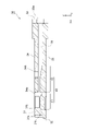
- FIG. 2 is a cross-sectional view showing the optical connector of FIG.
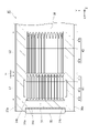
- FIG. 3 is a perspective view showing a ferrule according to an embodiment.
- FIG. 4 is a cross-sectional view showing the ferrule of FIG.
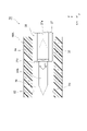
- FIG. 5 is an enlarged cross-sectional view of a part of the ferrule of FIG.
- FIG. 6 is another cross-sectional view showing the ferrule of FIG.
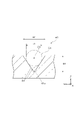
- FIG. 7A is a cross-sectional view showing a straight portion of the first fiber groove portion.
- FIG. 7B is a cross-sectional view showing a straight portion of the second fiber groove portion.
- FIG. 8 is a cross-sectional view showing a tapered portion of the second fiber groove portion.
- FIG. 9A is a cross-sectional view showing a modified example of the shape of the second fiber groove portion.
- FIG. 9B is a cross-sectional view showing another modification of the shape of the second fiber groove portion.
- FIG. 9C is a cross-sectional view showing another modification of the shape of the second fiber groove portion.
- FIG. 10 is a perspective view showing an optical connection structure including an optical connector.
- 11 is a plan view showing the optical connection structure of FIG. 10.
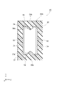
- FIG. FIG. 12 is a rear view showing the optical connection structure of FIG.
- FIG. 13 is a rear view showing a modified example of the adapter having an optical connection structure.
- FIG. 14 is a diagram showing how the optical connector is inserted into the adapter of FIG.
- the ferrule according to the embodiment of the present disclosure is a first aspect between the tip surface, an opening provided on the side opposite to the tip surface in the first direction intersecting the tip surface, and the tip surface and the opening.
- a plurality of fiber grooves extending along a direction and arranged along a second direction intersecting the first direction, each capable of supporting a plurality of optical fibers, and an extension line of the plurality of fiber grooves, respectively. It is equipped with multiple lenses.
- the fiber groove has a first fiber groove portion for positioning the optical fiber with respect to the lens, and a second fiber groove portion for introducing the optical fiber into the first fiber groove portion.
- the first fiber groove portion is arranged closer to the lens than the second fiber groove portion in the first direction.
- the fiber groove of this ferrule has a second fiber groove for introducing an optical fiber into the first fiber groove in addition to the first fiber groove for positioning the optical fiber with respect to the lens.
- the first fiber groove portion is arranged closer to the lens than the second fiber groove portion in the first direction. Therefore, when the optical fiber is inserted into the ferrule through the opening, the optical fiber is introduced into the first fiber groove by the second fiber groove, and the optical fiber is positioned with respect to the lens in the first fiber groove.
- the existence of the second fiber groove portion for introducing the optical fiber into the first fiber groove portion causes the optical fiber to collide with the wall portion between the fiber grooves when the optical fiber is inserted inside the ferrule. This can be reduced and the optical fiber can be reliably arranged in the first fiber groove portion. Therefore, according to the above-mentioned ferrule, workability when assembling the optical fiber can be improved.
- each of the first fiber groove portion and the second fiber groove portion may have a V shape. In this case, the position of the optical fiber with respect to the lens can be positioned more accurately.
- the opening width of the second fiber groove portion may be larger than the opening width of the first fiber groove portion.
- the allowable amount of deviation of the optical fiber supported by the second fiber groove with respect to the lens should be larger than the allowable amount of deviation of the optical fiber supported by the first fiber groove with respect to the lens.
- the diameter of the virtual circle centered on the optical axis of the lens and inscribed in the second fiber groove is larger than the diameter of the virtual circle centered on the optical axis of the lens and inscribed in the first fiber groove. May be large.
- the allowable amount of deviation of the optical fiber supported by the second fiber groove with respect to the lens should be larger than the allowable amount of deviation of the optical fiber supported by the first fiber groove with respect to the lens. Can be done.
- the position of the optical fiber with respect to the lens is determined in the second fiber groove, and then the position of the optical fiber with respect to the lens is determined in the first fiber groove with high accuracy. Can be done.
- the second fiber groove portion has a straight portion having a constant diameter of a virtual circle inscribed in the second fiber groove portion and centered on the optical axis of the lens at each position along the first direction, and a straight portion in the first direction.
- a tapered portion which is arranged on the opposite side of the first fiber groove portion and is inclined so that the diameter of the virtual circle inscribed in the second fiber groove portion becomes larger with respect to the optical axis of the lens as the distance from the straight portion increases. May include. The presence of such a tapered portion allows the optical fiber inserted into the inside of the ferrule from the opening to be reliably attracted to the straight portion.
- the presence of the straight portion enables the posture of the optical fiber to be stabilized along the first direction, and the optical fiber can be smoothly introduced into the first fiber groove portion with the posture stabilized. can. Therefore, according to the above-described configuration, the optical fiber can be reliably and smoothly introduced into the first fiber groove portion.
- the total length of the second fiber groove portion in the first direction may be equal to or greater than the total length of the first fiber groove portion in the first direction. In this case, the posture of the optical fiber can be more reliably stabilized in the second fiber groove portion.
- the second fiber groove may be arranged at a predetermined distance from the first fiber groove.
- the first fiber groove portion can be manufactured with high accuracy.
- an upper surface arranged at a position facing a plurality of fiber grooves in a third direction intersecting the first direction and the second direction may be further provided.
- the upper surface may have a window portion that opens in a region facing the first fiber groove portion in the third direction.
- the first fiber groove portion may be contained inside the window portion.
- the window portion can be used not only as an injection window portion for injecting an adhesive into the ferrule, but also for an alignment operation when introducing an optical fiber into the first fiber groove portion. This makes it possible to further improve workability when assembling the optical fiber.
- the above-mentioned ferrule may further include a pair of side surfaces arranged at positions facing each other across a plurality of fiber grooves in the second direction.
- a guide portion for guiding insertion into the adapter along the first direction may be provided on each of the pair of side surfaces.
- the guide portions provided on the pair of side surfaces can be used for positioning the ferrule with respect to the adapter. This makes it possible to position the ferrule with respect to the adapter without using expensive guide pins.
- the optical connector according to the embodiment of the present disclosure includes any of the above-mentioned ferrules and a plurality of optical fibers supported by a plurality of fiber grooves and arranged on the optical axes of the plurality of lenses. Since this optical connector includes any of the above-mentioned ferrules, workability when assembling the optical fiber to the ferrule can be improved as described above.
- the optical fiber may be fixed to the first fiber groove portion by an adhesive.
- the positioning of the optical fiber with respect to the lens can be performed more reliably.
- the ferrule has an upper surface arranged at a position facing a plurality of fiber grooves in a third direction intersecting the first direction and the second direction, and the upper surface has a first fiber groove portion and a third direction. It may have a window portion that opens in a region facing the light. Inside the window portion, a lid portion arranged on the first fiber groove portion via an optical fiber may be provided. In this case, the lid portion presses the optical fiber against the first fiber groove portion, so that the positioning of the optical fiber with respect to the lens can be performed more reliably.
- FIG. 1 is a perspective view showing an optical connector 10 according to this embodiment.
- FIG. 2 is a cross-sectional view showing the optical connector 10.
- Each figure shows an XYZ Cartesian coordinate system for ease of understanding.
- the longitudinal direction of the optical connector 10 is the X direction (first direction)
- the lateral direction of the optical connector 10 is the Y direction (second direction)
- the height direction of the optical connector 10 is the Z direction (first direction). 3 directions).
- the explanation may be given by defining the directions as "front” and "rear”. Of the X directions, the direction from the optical connector 10 toward the optical connector 10 (see FIG. 10) of the connection partner is defined as "front”, and the opposite direction is defined as "rear”.
- the optical connector 10 includes a plurality of (12 in this embodiment) optical fibers 20 and a ferrule 30 into which a front end portion of the plurality of optical fibers 20 is inserted.
- Each optical fiber 20 extends along the X direction and is arranged in a row along the Y direction.
- Each optical fiber 20 may be a multimode optical fiber (MMF: Multi-ModeFiber) or a single mode optical fiber (SMF: Single-ModeFiber).
- MMF Multi-ModeFiber
- SMF Single-ModeFiber
- the number of the optical fibers 20 is not limited to 12, and may be another number such as, for example, 4, 8, or 16.
- the ferrule 30 holds a plurality of optical fibers 20.
- the ferrule 30 has, for example, a substantially rectangular parallelepiped appearance.
- the ferrule 30 has a lens portion 31 at its front end.
- the ferrule 30 is integrally configured with, for example, the lens unit 31. That is, the ferrule 30 is integrally molded with the lens portion 31. Therefore, the ferrule 30 is made of the same material as the lens portion 31, that is, a light-transmitting material that can form the lens portion 31.
- the ferrule 30 is composed of, for example, PPS (polyphenylene sulfide), PEI (polyetherimide), PC (polycarbonate), PMMA (polymethylmethacrylate), PES (polyethersulphon), COP (cycloolefin polymer), or the like. Can be.
- PPS polyphenylene sulfide
- PEI polyetherimide
- PC polycarbonate
- PMMA polymethylmethacrylate
- PES polyethersulphon
- COP cycloolefin polymer
- the lens unit 31 is provided in front of the plurality of optical fibers 20 and faces the plurality of optical fibers 20 in the X direction.
- the lens portion 31 has, for example, a plate shape along the YZ plane.
- the lens unit 31 includes a front end surface 31a located at the front end in the X direction, a rear end surface 31b located at the rear end in the X direction, and a plurality of lenses 31c provided on the front end surface 31a.
- the front end surface 31a and the rear end surface 31b are, for example, planes parallel to the YZ plane.
- the rear end surface 31b faces a plurality of optical fibers 20 in the X direction.
- Each lens 31c is a convex lens that protrudes forward from the front end surface 31a.
- the lenses 31c are arranged in a row along the Y direction so as to correspond to the positions of the optical fibers 20.
- Each lens 31c is arranged on the optical axis of each optical fiber 20 and is optically coupled to each optical fiber 20. For example, when viewed from the X direction, the optical axis of each lens 31c coincides with the optical axis of each optical fiber 20.
- the light emitted from each optical fiber 20 is converted into parallel light (that is, collimated light) by each lens 31c, and then incident on the optical connector 10 (see FIG. 10) of the connection partner.
- the optical axis of the optical fiber 20 and the optical axis of the lens 31c may be deviated from each other.
- the front end surface of the optical fiber 20 or the front end surface 31a of the lens portion 31 may be inclined by, for example, 8 ° with respect to the YZ plane.
- the ferrule 30 has four outer surfaces that connect the front end surface 32 (tip surface) located at the front end in the X direction, the rear end surface 33 located at the rear end in the X direction, and the front end surface 32 and the rear end surface 33 in the X direction. It has sides 34, 35, 36, and 37.
- the front end surface 32 and the rear end surface 33 are, for example, along the YZ plane.
- the front end surface 32 is located at a position slightly protruding forward from the front end surface 31a of the lens portion 31.
- the rear end surface 33 includes an opening 33a (see FIG. 2) that collectively receives a plurality of optical fibers 20.
- the opening 33a is a portion of the rear end surface 33 that opens in the X direction.
- the outer surface 34 and the outer surface 35 face each other in the Z direction and extend along the XY plane.
- the outer side surface 34 faces one side in the Z direction and constitutes the upper surface of the ferrule 30.
- the outer side surface 35 faces the other side in the Z direction and constitutes the lower surface of the ferrule 30.
- the outer side surface 34 is located at a position facing the plurality of fiber grooves 40 described later in the Z direction.
- the outer side surface 34 is provided with two window portions 34a and window portions 34b that open in the Z direction.
- the window portion 34a is arranged closer to the front end surface 32 than the window portion 34b in the X direction.
- the window portion 34a is arranged, for example, behind the lens portion 31.
- the width of the window portion 34a in the Y direction is equal to or wider than the total width of the plurality of optical fibers 20 in the Y direction.
- the window portion 34b is provided at a position separated rearward from the window portion 34a at a predetermined distance.
- the width of the window portion 34b in the Y direction is, for example, narrower than the width of the window portion 34a in the Y direction.
- the number of windows opened on the outer side surface 34 is not limited to two, and may be one or three or more.
- the outer surface 36 and the outer surface 37 are arranged at positions facing each other in the Y direction, and form a pair of side surfaces of the ferrule 30.
- the outer side surface 36 and the outer surface 37 are provided with V-grooves 36a and V-grooves 37a (guide portions) for guiding the insertion of the ferrule 30 into the adapter 50 (see FIG. 10) described later, respectively.
- the V-groove 36a and the V-groove 37a are arranged at positions symmetrical with each other with respect to the center of the ferrule 30 in the Y direction, for example.
- the V-groove 36a is recessed from the outer surface 36 in the Y direction to the inside of the ferrule 30 (that is, the side from the outer surface 36 toward the outer surface 37), and is recessed in the Y direction to the outside of the ferrule 30 (that is, with respect to the outer surface 36). (The side opposite to the outer surface 37).
- the V-groove 36a has a V-shape in a YZ cross section, and the bottom of the V-groove 36a is, for example, rounded.
- the V-groove 36a extends linearly along the X direction on the outer surface 36.
- the V-groove 36a extends continuously along the X direction from the front end surface 32 to the rear end surface 33 on the outer surface 36, for example. That is, the V-groove 36a extends over the entire length of the ferrule 30 in the X direction.
- the V-groove 37a is recessed from the outer surface 37 in the Y direction to the inside of the ferrule 30, and is open to the outside of the ferrule 30 in the Y direction.
- the V-groove 37a has the same shape as, for example, the V-groove 36a.
- the V-groove 37a extends linearly along the X direction on the outer surface 37.
- the V-groove 37a extends continuously along the X direction from the front end surface 32 to the rear end surface 33 on the outer surface 37, for example. That is, the V groove 37a extends over the entire length of the ferrule 30 in the X direction.
- the ferrule 30 supports an accommodation hole 39 accommodating a plurality of optical fibers 20 received from the opening 33a of the rear end surface 33 and a plurality of optical fibers 20 accommodated in the accommodation hole 39, respectively.
- a plurality of fiber grooves 40 and a plurality of fiber grooves 40 are provided inside the ferrule 30.
- the accommodating hole 39 extends from the opening 33a of the rear end surface 33 to the rear end surface 31b of the lens portion 31 along the X direction.
- the accommodating hole 39 communicates with the window portion 34a and the window portion 34b provided on the outer surface 34 in the Z direction.
- the plurality of fiber grooves 40 extend along the X direction from the central portion of the accommodating hole 39 in the X direction to the front end portion of the accommodating hole 39.
- the front ends of the plurality of fiber grooves 40 are located at positions facing the window portion 34a in the Z direction.
- the rear ends of the plurality of fiber grooves 40 are located behind the window portion 34b.
- the plurality of fiber grooves 40 are arranged along the Y direction so as to correspond to the plurality of lenses 31c, respectively. That is, the plurality of lenses 31c are arranged on the extension lines of the plurality of fiber grooves 40, respectively. Therefore, the plurality of lenses 31c face each of the plurality of optical fibers 20 supported by the plurality of fiber grooves 40 in the X direction.
- the adhesive A injected from the window portion 34a is provided on the plurality of fiber grooves 40.
- the adhesive A is made of, for example, a light-transmitting material.
- Each optical fiber 20 is fixed to each fiber groove 40 by the adhesive A.
- a lid portion B is provided inside the window portion 34a on each fiber groove 40.
- the lid portion B is a plate-shaped member along the XY plane, and is configured separately from the ferrule 30.
- the lid portion B is made of, for example, a light-transmitting glass plate or a resin.
- the lid portion B is placed on each optical fiber 20 supported by each fiber groove 40, and is arranged so as to press each optical fiber 20 into each fiber groove 40.
- the lid portion B is arranged in, for example, a region inside the window portion 34a that faces the straight portion 41b (see FIG. 5) of the first fiber groove portion 41, which will be described later, in the Z direction, and is arranged on the straight portion 41b. Are in contact.
- the lid portion B is arranged so as to fit inside the window portion 34a, but a part of the lid portion B may protrude outward from the window portion 34a in the Z direction. That is, a part of the lid portion B may protrude upward from the window portion 34a.
- the adhesive A may enter the gap between the lid portion B and each fiber groove 40, or may enter the inside of each fiber groove 40 (that is, the gap between each optical fiber 20 and each fiber groove 40). May be good.
- FIG. 3 is a perspective view showing the ferrule 30.
- FIG. 4 is a cross-sectional view showing the ferrule 30.
- FIG. 4 shows an XZ cross section of the ferrule 30.
- the fiber groove 40 includes a first fiber groove 41 and a second fiber groove 42 in this order from the lens portion 31 side in the X direction.
- the first fiber groove portion 41 is arranged behind the lens portion 31.
- the second fiber groove portion 42 is arranged further behind the first fiber groove portion 41. Therefore, the first fiber groove portion 41 is arranged closer to the lens portion 31 than the second fiber groove portion 42 in the X direction.
- the second fiber groove portion 42 is arranged on the side opposite to the lens portion 31 with respect to the first fiber groove portion 41 in the X direction.
- Each of the first fiber groove portion 41 and the second fiber groove portion 42 is, for example, a V groove. That is, each of the first fiber groove portion 41 and the second fiber groove portion 42 has a V shape that opens upward (that is, in the direction from the outer surface 35 to the outer surface 34 in the Z direction) in the YZ cross section.
- the first fiber groove portion 41 is provided for positioning the optical fiber 20 with respect to the lens 31c with high accuracy. Therefore, the first fiber groove 41 is formed with high accuracy so that the optical axis of the optical fiber 20 supported by the first fiber groove 41 is aligned with or extremely close to the optical axis of the lens 31c when viewed from the X direction. Has been done.
- the optical fiber 20 supported by the first fiber groove portion 41 is in a state of being centered with high accuracy with respect to the lens 31c.
- the second fiber groove 42 is provided for introducing the optical fiber 20 into the first fiber groove 41.
- the second fiber groove 42 determines the approximate position of the optical fiber 20 with respect to the lens 31c in order to facilitate the introduction of the optical fiber 20 inserted into the ferrule 30 from the opening 33a into the first fiber groove 41. That is, the second fiber groove portion 42 roughly positions the optical fiber 20 with respect to the lens 31c before positioning the optical fiber 20 in the first fiber groove portion 41 with high accuracy. Therefore, when the optical fiber 20 is supported by the second fiber groove 42, the optical axis of the optical fiber 20 is displaced with respect to the optical axis of the lens 31c as compared with the state where the optical fiber 20 is supported by the first fiber groove 41. A large amount of allowance is secured. Therefore, before reaching the first fiber groove portion 41, the optical fiber 20 supported by the second fiber groove portion 42 is in a state of being roughly positioned with respect to the lens 31c.
- FIG. 5 is an enlarged cross-sectional view showing the vicinity of the first fiber groove portion 41 and the second fiber groove portion 42 of FIG.
- FIG. 6 is another cross-sectional view showing the vicinity of the first fiber groove portion 41 and the second fiber groove portion 42.
- FIG. 5 shows an XZ cross section of the ferrule 30.
- FIG. 6 shows an XY cross section of the ferrule 30.
- the first fiber groove portion 41 is formed at a position facing the window portion 34a in the Z direction.
- the first fiber groove portion 41 is housed inside the window portion 34a and does not exist outside the window portion 34a.
- the total length L1 of the first fiber groove portion 41 in the X direction is shorter than the width of the window portion 34a in the X direction and longer than the width of the lid portion B (see FIG. 2) arranged inside the window portion 34a in the X direction. ..
- the total width of all the first fiber groove portions 41 in the Y direction is smaller than the width of the window portion 34a in the Y direction.
- the total length L1 of the first fiber groove 41 is set, for example, in a range of 3 times or more and 40 times or less the diameter of the optical fiber 20.
- the diameter of the optical fiber 20 here means 0.125 mm, which is the diameter of a general-purpose optical fiber.
- the second fiber groove portion 42 is not formed at a position facing the window portion 34a in the Z direction.
- the second fiber groove portion 42 is arranged rearward with a predetermined distance from the window portion 34a and the first fiber groove portion 41 in the X direction. As shown in FIGS. 5 and 6, the second fiber groove portion 42 is arranged rearward by a distance R from the first fiber groove portion 41 in the X direction.
- the distance R is set, for example, in the range of 0.01 mm or more and 3 mm or less.
- the second fiber groove portion 42 is formed at a position facing the window portion 34b behind the window portion 34a in the Z direction.
- the window portion 34b is provided, for example, at a position facing the central portion of the second fiber groove portion 42 in the X direction in the Z direction.
- the total length L2 of the second fiber groove portion 42 in the X direction is longer than the width of the window portion 34b in the X direction.
- the total length L2 of the second fiber groove portion 42 in the X direction is set to be equal to or greater than the total length L1 of the first fiber groove portion 41 in the X direction. That is, the total length L2 of the second fiber groove portion 42 is the same as the total length L1 of the first fiber groove portion 41, or is longer than the total length L1 of the first fiber groove portion 41.
- the total length L2 of the second fiber groove portion 42 means the length of the entire second fiber groove portion 42 including the straight portion 42a and the tapered portion 42b, which will be described later, in the X direction.
- the first fiber groove portion 41 has a tapered portion 41a (second tapered portion), a straight portion 41b, and a tapered portion 41c (first taper) in this order from the lens portion 31 side in the X direction. Part) and includes.
- the straight portion 41b is a portion extending linearly along the X direction behind the lens portion 31.
- the YZ cross-sectional shape (that is, the opening shape of the V groove) of the first fiber groove portion 41 is constant at each position along the X direction.
- the straight portion 41b is formed so as to position the position of the optical fiber 20 with respect to the lens 31c with high accuracy.
- FIG. 7A is a cross-sectional view showing a straight portion 41b of the first fiber groove portion 41.
- FIG. 7A shows a virtual circle C1 inscribed in a pair of inner surfaces S1 and S1 constituting the straight portion 41b.
- the center C0 of the virtual circle C1 coincides with the optical axis of the lens 31c (see FIGS. 5 and 6) when viewed from the X direction, and the diameter d1 of the virtual circle C1 is the optical fiber 20 (FIGS. 1 and 6). 2) is the same as the diameter.
- the optical axis of the optical fiber 20 in a state of being supported by the straight portion 41b coincides with the optical axis of the lens 31c when viewed from the X direction. Therefore, in FIG.
- the two-dot chain line showing the virtual circle C1 shows the outer shape of the optical fiber 20 in a state of being supported by the straight portion 41b.
- the center C0 of the virtual circle C1 does not have to be exactly aligned with the optical axis of the lens 31c when viewed from the X direction, and may be slightly deviated from the optical axis of the lens 31c.
- the shape of the straight portion 41b is designed so that the optical axis of the optical fiber 20 supported by the straight portion 41b coincides with or is extremely close to the optical axis of the lens 31c.
- the optical fiber 20 is positioned with high accuracy in the straight portion 41b. Therefore, in a state where the optical fiber 20 is supported by the straight portion 41b, the optical fiber 20 is centered with high accuracy with respect to the lens 31c.
- the straight portion 41b since the YZ cross-sectional shape of the first fiber groove portion 41 is constant at each position along the X direction, the diameter d1 of the virtual circle C1 is also constant at each position along the X direction.
- the opening width W1 and the depth D1 of the first fiber groove portion 41 are also constant at each position of the straight portion 41b along the X direction.
- the opening width W1 of the first fiber groove portion 41 is the maximum width of the opening portion of the first fiber groove portion 41 in the Y direction. More specifically, the opening width W1 of the first fiber groove portion 41 is the width in the Y direction of the opening portion of the first fiber groove portion 41 on the forming surface on which the first fiber groove portion 41 is formed.
- the depth D1 of the first fiber groove portion 41 is the distance in the Z direction from the forming surface of the first fiber groove portion 41 to the bottom portion of the first fiber groove portion 41.
- the tapered portion 41a of the first fiber groove portion 41 is located in front of the straight portion 41b. Specifically, the tapered portion 41a extends from the front end of the straight portion 41b in the X direction to a position in front of the lens portion 31 (that is, a position slightly separated rearward from the rear end surface 31b of the lens portion 31). There is. Therefore, the tapered portion 41a is arranged between the lens portion 31 and the straight portion 41b in the X direction. In the tapered portion 41a, the YZ cross-sectional shape of the first fiber groove portion 41 changes at each position along the X direction. The tapered portion 41a is inclined so that the diameter d1 (see FIG.
- the inclination of the tapered portion 41a may be a linear inclination or a curved inclination in the XZ cross section shown in FIG.
- the diameter d1 of the virtual circle C1 at the rear end of the tapered portion 41a is the same as the diameter d1 of the virtual circle C1 at the straight portion 41b
- the diameter d1 of the virtual circle C1 at the front end of the tapered portion 41a is the diameter d1 of the virtual circle C1 at the straight portion 41b. It is larger than the diameter d1 of the virtual circle C1.
- the opening width W1 of the first fiber groove portion 41 is constant at each position along the X direction, while the depth D1 of the first fiber groove portion 41 becomes deeper as the distance from the straight portion 41b increases in the X direction. (See FIG. 7A).
- the presence of such a tapered portion 41a makes it possible to secure a space in front of the straight portion 41b to allow the adhesive A (see FIG. 2).
- the tapered portion 41c of the first fiber groove portion 41 extends further rearward from the rear end of the straight portion 41b.
- the tapered portion 41c is arranged between the straight portion 41b and the second fiber groove portion 42 in the X direction.
- the YZ cross-sectional shape of the first fiber groove portion 41 changes at each position along the X direction.
- the tapered portion 41c is inclined so that the diameter d1 (see FIG. 7A) of the virtual circle C1 increases as the distance from the straight portion 41b increases in the X direction.
- the inclination of the tapered portion 41c may be a linear inclination or a curved inclination in the XZ cross section shown in FIG.
- the diameter d1 of the virtual circle C1 at the front end of the tapered portion 41c becomes the same as the diameter d1 of the virtual circle C1 at the straight portion 41b, and the diameter d1 of the virtual circle C1 at the rear end of the tapered portion 41c is the diameter d1 of the virtual circle C1 at the straight portion 41b. It is larger than the diameter d1 of the virtual circle C1. Therefore, among the diameters d1 of the virtual circle C1 at each position along the X direction of the first fiber groove portion 41, the diameter d1 of the virtual circle C1 in the straight portion 41b is the smallest.
- the opening width W1 of the first fiber groove portion 41 is constant at each position along the X direction, while the depth D1 of the first fiber groove portion 41 becomes deeper as the distance from the straight portion 41b increases in the X direction. (See FIG. 7A).
- the presence of such a tapered portion 41c allows the optical fiber 20 from the second fiber groove portion 42 to be attracted to the straight portion 41b of the first fiber groove portion 41. Therefore, the tapered portion 41c functions as a guide portion for guiding the optical fiber 20 from the second fiber groove portion 42 to the straight portion 41b.
- the second fiber groove portion 42 includes a straight portion 42a and a tapered portion 42b in order from the first fiber groove portion 41 side in the X direction.
- the straight portion 42a is a portion extending linearly along the X direction behind the first fiber groove portion 41.
- the straight portion 42a extends rearward from a position separated by a distance R from the rear end of the tapered portion 41c of the first fiber groove portion 41.
- the tapered portion 42b extends further rearward from the rear end of the straight portion 42a. Therefore, the tapered portion 42b is arranged on the side opposite to the first fiber groove portion 41 with respect to the straight portion 42a in the X direction.
- the window portion 34b is arranged at a position facing the connecting portion between the straight portion 42a and the tapered portion 42b in the Z direction.
- the YZ cross-sectional shape (that is, the opening shape of the V groove) of the second fiber groove portion 42 is constant at each position along the X direction.
- the straight portion 42a is formed so as to roughly determine the position of the optical fiber 20 with respect to the lens 31c. Therefore, the optical fiber 20 supported by the straight portion 42a is in a state of being roughly positioned with respect to the lens 31c.
- FIG. 7B is a cross-sectional view showing a straight portion 42a of the second fiber groove portion 42.
- FIG. 7B shows the virtual circle C1 shown in FIG. 7A and the virtual circle C2 inscribed in the pair of inner surfaces S2 and S2 constituting the straight portion 42a.
- the virtual circle C2 forms a concentric circle having a diameter d2 larger than that of the virtual circle C1 with the center C0 of the virtual circle C1 (that is, the optical axis of the lens 31c) as the center. Therefore, the allowable amount of deviation of the optical fiber 20 supported by the straight portion 42a of the second fiber groove portion 42 with respect to the lens 31c is the deviation of the optical fiber 20 supported by the straight portion 41b of the first fiber groove portion 41 with respect to the lens 31c. It is secured larger than the allowable amount of. As described above, the shape of the straight portion 42a is formed so as to roughly position the optical fiber 20 with respect to the lens 31c.
- the opening width W2 and the depth D2 of the second fiber groove portion 42 are also constant at each position of the straight portion 42a along the X direction.
- the opening width W2 of the second fiber groove portion 42 is the maximum width of the opening portion of the second fiber groove portion 42 in the Y direction. More specifically, the opening width W2 of the second fiber groove portion 42 is the width in the Y direction of the opening portion of the second fiber groove portion 42 on the forming surface on which the second fiber groove portion 42 is formed.
- the depth D2 of the second fiber groove portion 42 is the distance in the Z direction from the forming surface of the second fiber groove portion 42 to the bottom portion of the second fiber groove portion 42.
- the diameter d2 of the virtual circle C2 is larger than the diameter d1 of the virtual circle C1. Therefore, the opening width W2 of the straight portion 42a is larger than the opening width W1 of the straight portion 41b, and the depth D2 of the straight portion 42a is deeper than the depth D1 of the straight portion 41b.
- FIG. 8 is a cross-sectional view showing a tapered portion 42b of the second fiber groove portion 42.
- FIG. 8 shows the virtual circle C2 inscribed in the pair of inner surfaces S3 and S3 constituting the tapered portion 42b together with the virtual circle C2 shown in FIG. 7B.
- the virtual circle C3 forms a concentric circle having a diameter d3 larger than that of the virtual circle C2 with the center C0 of the virtual circle C1 (that is, the optical axis of the lens 31c) as the center.
- the YZ cross-sectional shape of the second fiber groove portion 42 changes at each position along the X direction.
- the tapered portion 42b is inclined so that the diameter d3 of the virtual circle C3 becomes larger as the distance from the straight portion 42a increases in the X direction.
- the inclination of the tapered portion 42b may be a linear inclination or a curved inclination in the XZ cross section shown in FIG.
- the diameter d3 of the virtual circle C3 at the rear end of the tapered portion 42b becomes larger than the diameter d2 of the virtual circle C2 at the straight portion 42a.
- the diameter d3 of the virtual circle C3 at the front end of the tapered portion 42b is the same as the diameter d2 of the virtual circle C2 at the straight portion 42a. Therefore, among the virtual circles C2 and C3 at each position along the X direction of the second fiber groove portion 42, the diameter d2 of the virtual circle C2 in the straight portion 42a is the smallest.
- the diameter d1 of the virtual circle C1 in the straight portion 41b of the first fiber groove portion 41 is smaller than the diameter d2 of the virtual circle C2 in the straight portion 42a of the second fiber groove portion 42.
- the opening width W2 of the second fiber groove portion 42 is constant at each position along the X direction, while the depth D3 of the second fiber groove portion 42 becomes deeper as the distance from the straight portion 42a increases in the X direction. (See Fig. 8).
- the presence of such a tapered portion 42b allows the optical fiber 20 inserted through the opening 33a to be attracted to the straight portion 42a. Therefore, the tapered portion 42b functions as a guide portion that guides the optical fiber 20 to the straight portion 42a.
- each optical fiber 20 inserted into the accommodating hole 39 is arranged in each fiber groove 40.
- the optical fiber 20 is guided to the straight portion 42a by the tapered portion 42b of the second fiber groove portion 42.
- the optical fiber 20 is corrected to a state along the X direction in the straight portion 42a, and an approximate position with respect to the lens 31c is determined. In this way, the optical fiber 20 is roughly positioned in the second fiber groove portion 42.
- the optical fiber 20 is introduced from the straight portion 42a of the second fiber groove portion 42 to the tapered portion 41c of the first fiber groove portion 41. Then, the optical fiber 20 is guided from the tapered portion 41c to the straight portion 41b. The optical fiber 20 is corrected to a state along the X direction in the straight portion 41b, and a precise position with respect to the lens 31c is determined. In this way, the optical fiber 20 is positioned with high accuracy in the first fiber groove portion 41. That is, when viewed from the X direction, the optical axis of the optical fiber 20 supported by the straight portion 41b is arranged so as to coincide with or very close to the optical axis of the lens 31c.
- the optical fiber 20 is passed from the straight portion 41b to the tapered portion 41a and comes into contact with the rear end surface 31b of the lens portion 31.
- the optical fiber 20 may be separated from the rear end surface 31b of the lens portion 31. That is, the optical fiber 20 may be arranged at a predetermined interval with respect to the rear end surface 31b of the lens portion 31.
- the adhesive A is injected into the ferrule 30 from the window portion 34a, and the lid portion B is arranged in the window portion 34a (see FIG. 2).
- the adhesive A injected into the ferrule 30 also spreads over the gap between the lid portion B and each optical fiber 20.
- Each optical fiber 20 is fixed to each fiber groove 40 by curing the adhesive A in a state where the lid portion B presses each optical fiber 20 into each fiber groove 40. As a result, the position of each optical fiber 20 with respect to the ferrule 30 is fixed.
- the configurations of the first fiber groove portion 41 and the second fiber groove portion 42 are not limited to the above-mentioned configurations, and can be appropriately changed.
- the second fiber groove portion 42 may be a groove having a shape different from that of the first fiber groove portion 41. That is, the second fiber groove portion 42 is not limited to the V groove having a V shape in the YZ cross section, and may be a groove having another shape.
- 9A, 9B, and 9C are cross-sectional views showing a modified example of the shape of the second fiber groove portion 42.
- the second fiber groove portion 42A may be a semicircular groove having a semicircular shape in the YZ cross section.
- the second fiber groove portion 42B may be a rectangular groove having a rectangular shape in a YZ cross section.
- the second fiber groove portion 42C may be a U-groove having a U-shape in the YZ cross section.
- the first fiber groove portion 41 does not necessarily have to be a V groove, and may be a groove having another shape.
- the second fiber groove portion 42 may not be separated from the first fiber groove portion 41 in the X direction, and may be directly connected to the first fiber groove portion 41 in the X direction.
- the second fiber groove portion 42 does not have to include the tapered portion 42b, and may include only the straight portion 42a.
- the second fiber groove portion 42 may not include the straight portion 42a, and may include only the tapered portion 42b.
- the first fiber groove portion 41 may not include the tapered portion 41a and the tapered portion 41c, and may include only the straight portion 41b.
- the total length L2 of the second fiber groove portion 42 may be shorter than the total length L1 of the first fiber groove portion 41.
- FIG. 10 is a perspective view showing the optical connection structure 1.
- FIG. 11 is a plan view showing the optical connection structure 1.
- FIG. 12 is a rear view showing the optical connection structure 1.
- an optical connector 10 in a state in which a plurality of optical fibers 20 are omitted is shown.
- the adapter 50 of the optical connection structure 1 is shown as a cut surface when cut in the XY plane.
- the optical connection structure 1 includes a pair of optical connectors 10 and 10 arranged so as to face each other in the X direction, and an adapter 50 into which the pair of optical connectors 10 and 10 are inserted. It is equipped with.
- the pair of optical connectors 10 and 10 are arranged upside down.
- a pair of optical connectors 10 and 10 are fitted to the adapter 50 so that the ferrules 30 and 30 face each other inside the adapter 50.
- the pair of ferrules 30, 30 may abut against each other and may be in contact with each other, or may be arranged at a predetermined distance.
- the adapter 50 may be, for example, PEI (polyetherimide), PBT (polybutylene terephthalate), PPS (polyphenylene sulfide), PC (polycarbonate), PMMA (polymethylmethacrylate), PES (polyethersulfon), or PA ( It is made of an elastic material such as polyamide). From the viewpoint of reducing the difference between the coefficient of linear expansion of the material of the adapter 50 and the coefficient of linear expansion of the material of the ferrule 30, the material of the adapter 50 may be the same material as that of the ferrule 30.
- the adapter 50 has a cylindrical shape capable of accommodating a pair of ferrules 30 and 30, and extends along the X direction. In the X direction, the total length of the adapter 50 is longer than, for example, the total length of the total length of the pair of ferrules 30 and 30 connected to each other. As shown in FIG. 12, the adapter 50 has a rectangular tubular shape when viewed from the X direction.
- the adapter 50 has an insertion hole 51 that constitutes the inside of a rectangular cylinder.
- the insertion hole 51 is a through hole that penetrates the adapter 50 in the X direction.
- the insertion hole 51 has a rectangular shape when viewed from the X direction, and is composed of four inner surfaces 52, 53, 54, and 55.
- the inner surface 52 faces the outer surface 34 of the ferrule 30 in the Z direction, and the inner surface 53 faces the outer surface 35 of the ferrule 30 in the Z direction.
- the inner surface 54 faces the outer surface 36 of the ferrule 30 in the Y direction, and the inner surface 55 faces the outer surface 37 of the ferrule 30 in the Y direction.
- the inner surface 54 and the inner surface 55 are provided with V protrusions 54a and V protrusions 55a for guiding the V groove 36a and the V groove 37a of the ferrule 30, respectively.
- the V protrusion 54a and the V protrusion 55a are arranged at positions symmetrical with each other with respect to the center of the insertion hole 51 in the Y direction, for example.
- Each of the V protrusion 54a and the V protrusion 55a is a protrusion having a V shape in the YZ cross section.
- the V protrusion 54a projects from the inner surface 54 toward the outer surface 36 of the ferrule 30, and is in contact with the V groove 36a of the outer surface 36.
- the V protrusion 54a is provided, for example, on the inner surface 54 so as to extend continuously along the X direction.
- the V protrusion 55a projects from the inner surface 55 toward the outer surface 37 of the ferrule 30, and is in contact with the V groove 37a of the outer surface 37.
- the V protrusion 55a is provided, for example, on the inner surface 55 so as to extend continuously along the X direction.
- the V protrusion 54a has a shape corresponding to the V groove 36a.
- the opening angle of the V protrusion 54a (that is, the angle formed by the pair of outer surfaces constituting the V protrusion 54a) is larger than the opening angle of the V groove 36a of the ferrule 30 (that is, the angle formed by the pair of inner surfaces forming the V groove 36a). Is also set small.
- the top of the V protrusion 54a is, for example, rounded.
- the V protrusion 55a has a shape corresponding to the V groove 37a.
- the V protrusion 55a has, for example, the same shape as the V protrusion 54a.
- the separation distance in the Y direction between the V protrusion 54a and the V protrusion 55a is set to be slightly smaller than the width in the Y direction between the V groove 36a and the V groove 37a of the ferrule 30.
- the Y-direction separation distance between the V-projection 54a and the V-projection 55a is defined as the Y-direction distance between the top of the V-projection 54a and the top of the V-projection 55a when the ferrule 30 is not inserted into the adapter 50. can do.
- the width in the Y direction between the V-groove 36a and the V-groove 37a can be defined as the distance in the Y-direction between the bottom of the V-groove 36a and the bottom of the V-groove 37a.
- the adapter 50 has a hollow portion 61 provided on the outside of one of the insertion holes 51 in the Y direction.
- the hollow portion 61 is located outside the insertion hole 51 with the wall portion 54W constituting the inner surface 54 interposed therebetween in the Y direction. That is, the hollow portion 61 is adjacent to the insertion hole 51 via the wall portion 54W in the Y direction.
- the hollow portion 61 extends linearly along the X direction, for example, at a position aligned with the insertion hole 51 in the Y direction.
- the wall portion 54W extends in the Z direction between the hollow portion 61 and the insertion hole 51 so as to separate the hollow portion 61 and the insertion hole 51.
- the thickness of the wall portion 54W (that is, the width of the wall portion 54W in the Y direction) is, for example, constant.
- the thickness of the wall portion 54W is sufficiently thin to allow elastic deformation of the V protrusion 54a.
- the thickness of the wall portion constituting the inner surface 55 is also sufficiently thin to allow the elastic deformation of the V protrusion 55a.
- the presence of such a hollow portion 61 makes it easier to elastically deform the V protrusion 55a.
- No hollow portion is provided on the other outer side of the insertion hole 51 in the Y direction (that is, on the side opposite to the insertion hole 51 with respect to the inner surface 55 in the Y direction).
- the V-groove 36a and the V-groove 37a of the ferrule 30 are fitted into the V protrusion 54a and the V protrusion 55a of the adapter 50, respectively.
- the V protrusion 54a enters the V groove 36a of the ferrule 30 and abuts on it
- the V protrusion 55a enters the V groove 37a of the ferrule 30 and abuts on it.
- the separation distance between the V protrusion 54a and the V protrusion 55a of the adapter 50 is set to be smaller than the width between the V groove 36a and the V groove 37a of the ferrule 30.
- the V protrusion 54a and the V protrusion 55a of the adapter 50 receive a reaction force from the V groove 36a and the V groove 37a of the ferrule 30, and elastically deform to the outside of the ferrule 30 in the Y direction. Then, a force that causes the V protrusion 54a and the V protrusion 55a of the adapter 50 to return to their original positions is applied to the ferrule 30, and the ferrule 30 is sandwiched and fixed by the V protrusion 54a and the V protrusion 55a of the adapter 50. Will be.
- the V protrusion 54a and the V protrusion 55a of the adapter 50 come into contact with the V groove 36a and the V groove 37a of the ferrule 30, respectively. Therefore, the gap between the V protrusion 54a and the V groove 36a in the Y direction and the gap between the V protrusion 55a and the V groove 37a in the Y direction are zero. As a result, the position of the ferrule 30 with respect to the adapter 50 is defined in the YZ plane, and the position of the ferrule 30 with respect to the adapter 50 in the rotation direction is defined.
- a spring (not shown) attached to the rear of the ferrule 30 urges the ferrule 30 toward the connection partner ferrule 30 in the X direction, thereby defining the position of the ferrule 30 with respect to the adapter 50 in the X direction (not shown). 10 and 11). In this way, the position of the ferrule 30 with respect to the adapter 50 is defined.
- the gap between the V protrusion 54a and the V groove 36a in the Z direction (that is, the difference between the width of the V protrusion 54a in the Z direction and the width of the V groove 36a in the Z direction), and the Z of the V protrusion 55a and the V groove 37a.
- the ferrule 30 and the ferrule 30 of the connection partner are caused by the size of the gap. Positional deviation or angular deviation between the and can occur. Therefore, it is desirable to set these gaps to be as small as possible.
- both the V protrusion 54a and the V protrusion 55a are configured to be elastically deformable. ..
- the V projection 54a may be configured to be elastically deformable.
- the V protrusion 55a does not have to be configured to be elastically deformable.
- the hollow portion 61 is provided on the outside of the wall portion 54W where the V protrusion 54a is provided (that is, on the side opposite to the accommodating hole 39 with respect to the wall portion 54W).
- the V protrusion 54a can be elastically deformable.
- the V groove 37a of the ferrule 30 is arranged so as to abut against the V protrusion 55a that is not elastically deformed, and the V groove 36a of the ferrule 30 is arranged in the V protrusion 54a that is elastically deformed.
- the V protrusion 54a receives a reaction force from the V groove 36a and is elastically deformed, and a force for the V protrusion 54a to return to the original position is applied to the ferrule 30.
- the ferrule 30 is sandwiched and fixed by the V protrusion 54a and the V protrusion 55a, and the position of the ferrule 30 with respect to the adapter 50 is defined.
- the outer surface 36 and the outer surface 37 of the ferrule 30 are provided with V-grooves 36a and V-grooves 37a, respectively, but instead of the V-grooves 36a and the V-grooves 37a, grooves having other shapes are provided. May be provided.
- the outer surface 36 and the outer surface 37 of the ferrule 30 are provided with a U-shaped groove in the YZ cross section, a semicircular groove in the YZ cross section, or a rectangular groove in the YZ cross section. May be done.
- an elliptical protrusion having an elliptical shape in the YZ cross section instead of the V protrusion 54a and the V protrusion 55a, an elliptical protrusion having an elliptical shape in the YZ cross section, a semicircular protrusion having a semicircular shape in the YZ cross section, or A rectangular protrusion having a rectangular shape in the YZ cross section may be provided.
- protrusions may be provided on the outer surface 36 and the outer surface 37 of the ferrule 30, and grooves may be provided on the inner surface 54 and the inner surface 55 of the adapter 50.
- the combination of the grooves and protrusions in the ferrule 30 and the adapter 50 can be appropriately changed. ..
- the optical fiber 20 when the optical fiber 20 is inserted into the ferrule 30 from the opening 33a, the optical fiber 20 is introduced into the first fiber groove 41 by the second fiber groove 42, and the optical fiber is introduced in the first fiber groove 41. 20 is positioned with respect to the lens 31c.
- the presence of the second fiber groove portion 42 for introducing the optical fiber 20 into the first fiber groove portion 41 allows light to be applied to the wall portion between the fiber grooves 40 when the optical fiber 20 is inserted into the ferrule 30.
- the optical fiber 20 can be reliably arranged in the first fiber groove 41 by reducing the collision of the fibers 20. Therefore, according to the present embodiment, the workability when assembling the optical fiber 20 to the ferrule 30 can be improved.
- each of the first fiber groove portion 41 and the second fiber groove portion 42 has a V shape.
- the opening width W2 of the second fiber groove portion 42 is larger than the opening width W1 of the first fiber groove portion 41.
- the allowable amount of deviation of the optical fiber 20 supported by the second fiber groove 42 with respect to the lens 31c is larger than the allowable amount of deviation of the optical fiber 20 supported by the first fiber groove 41 with respect to the lens 31c.
- it can be secured to a large extent.
- the optical fiber 20 is inserted into the ferrule 30, after the approximate position of the optical fiber 20 with respect to the lens 31c is determined in the second fiber groove portion 42, the optical fiber 20 with respect to the lens 31c is determined in the first fiber groove portion 41. The position of can be determined with high accuracy. Therefore, according to the above-described configuration, the second fiber groove 42 for introducing the optical fiber 20 into the first fiber groove 41 can be suitably realized.
- the diameter d2 of the virtual circle C2 centered on the optical axis of the lens 31c and inscribed in the second fiber groove portion 42 is centered on the optical axis of the lens 31c and inside the first fiber groove portion 41. It is larger than the diameter d1 of the tangent virtual circle C1.
- the allowable amount of deviation of the optical fiber 20 supported by the second fiber groove 42 with respect to the lens 31c is larger than the allowable amount of deviation of the optical fiber 20 supported by the first fiber groove 41 with respect to the lens 31c.
- it can be secured to a large extent.
- the optical fiber 20 with respect to the lens 31c is determined in the first fiber groove portion 41.
- the position of can be determined with high accuracy. Therefore, according to the above-described configuration, the second fiber groove 42 for introducing the optical fiber 20 into the first fiber groove 41 can be suitably realized.
- the second fiber groove portion 42 has a straight portion 42a in which the diameter d2 of the virtual circle C2 is constant at each position along the X direction, and the diameter d3 of the virtual circle C3 increases as the distance from the straight portion 42a increases.
- a tapered portion 42b that is inclined so as to be included. The presence of such a tapered portion 42b ensures that the optical fiber 20 inserted into the ferrule 30 from the opening 33a is attracted to the straight portion 42a. Further, the presence of the straight portion 42a enables the posture of the optical fiber 20 to be stabilized along the X direction, and the optical fiber 20 is smoothly introduced into the first fiber groove portion 41 in the state where the posture is stabilized. Can be made to. Therefore, according to the above-described configuration, the optical fiber 20 can be reliably and smoothly introduced into the first fiber groove portion 41.
- the total length L2 of the second fiber groove portion 42 is equal to or greater than the total length L1 of the first fiber groove portion 41. As a result, the posture of the optical fiber 20 can be more reliably stabilized in the second fiber groove portion 42.
- the second fiber groove portion 42 is arranged at a predetermined distance from the first fiber groove portion 41.
- the first fiber groove 41 can be manufactured with high accuracy by forming the first fiber groove 41 separately from the second fiber groove 42.
- the first fiber groove portion 41 for positioning the optical fiber 20 with respect to the lens 31c can be suitably obtained.
- the first fiber groove portion 41 is housed inside the window portion 34a when viewed from the Z direction.
- the window portion 34a can be used not only as an injection window portion for injecting the adhesive A into the ferrule 30 but also for alignment work when introducing the optical fiber 20 into the first fiber groove portion 41. can. This makes it possible to further improve workability when assembling the optical fiber 20.
- the outer surface 36 and the outer surface 37 are provided with V-grooves 36a and V-grooves 37a for guiding insertion into the adapter 50 along the X direction, respectively.
- the position of the ferrule 30 with respect to the adapter 50 can be determined by using the V groove 36a and the V groove 37a. That is, the ferrule 30 can be positioned with respect to the adapter 50 without using an expensive guide pin.
- the optical fiber 20 is fixed to the first fiber groove 41 by the adhesive A.
- the position of the optical fiber 20 with respect to the lens 31c is fixed by the adhesive A, so that the positioning of the optical fiber 20 with respect to the lens 31c can be performed more reliably.
- the lid portion B arranged on the first fiber groove portion 41 via the optical fiber 20 is provided inside the window portion 34a.
- the lid portion B presses the optical fiber 20 against the first fiber groove portion 41 the positioning of the optical fiber 20 with respect to the lens 31c can be performed more reliably.
- FIG. 13 is a rear view showing a modified example of the above-mentioned optical connection structure 1.
- the adapter 50A is shown as a cut surface when the adapter 50A is cut on the YZ plane.
- the adapter 50A is made of a non-elastic material. Examples of the material of the adapter 50A include PPS (polyphenylene sulfide) and the like.
- the adapter 50A does not have the hollow portion 61 described above. In this case, even if a particularly hard material is not used as the material of the adapter 50A, elastic deformation of the adapter 50A is less likely to occur.
- the inner surface 54 and the inner surface 55 of the adapter 50A are provided with a semicircular protrusion 54b and a semicircular protrusion 55b, respectively, in place of the V protrusion 54a and the V protrusion 55a.
- Each of the semicircular protrusion 54b and the semicircular protrusion 55b is a protrusion having a semicircular shape in the YZ cross section.
- Each of the semicircular protrusion 54b and the semicircular protrusion 55b is in contact with the V groove 36a and the V groove 37a of the ferrule 30, respectively.
- the separation distance between the semicircular protrusion 54b and the semicircular protrusion 55b in the Y direction is slightly larger than the width between the V groove 36a and the V groove 37a of the ferrule 30 in the Y direction.
- the separation distance between the semicircular projection 54b and the semicircular projection 55b is the distance in the Y direction between the top of the semicircular projection 54b and the top of the semicircular projection 55b when the ferrule 30 is not inserted into the adapter 50A. Can be defined.
- a slight gap is formed between the semicircular protrusion 54b and the V groove 36a in the Y direction and between the semicircular protrusion 55b and the V groove 37a in the Y direction.
- FIG. 14 is a side view showing the optical connection structure 1A.
- it is shown as a cut surface when the adapter 50A is cut in the XZ plane.
- both ends of the semicircular projection 54b in the X direction are formed so as to taper as they are separated from each other in the X direction.
- the optical connection structure 1A according to the present modification also has the same effect as the optical connection structure 1 according to the above-described embodiment.
- the adapter 50A is made of a material that does not elastically deform as in this modification, the V-groove 36a and the V-groove 37a are tentatively fitted to the V protrusion 54a and the V protrusion 55a, respectively, as in the above-described embodiment.
- gaps are likely to occur between the V groove 36a and the V protrusion 54a in the Y direction and between the V groove 37a and the V protrusion 55a in the Y direction due to the influence of manufacturing tolerances and the like.
- ferrules and optical connectors of the present disclosure are not limited to the above-described embodiments and modifications, and various other modifications are possible.
- the ferrule configuration can be changed as appropriate.
- the ferrule in the above-described embodiment, the case where the ferrule is integrally formed with the lens portion is illustrated, but the ferrule may be configured separately from the lens portion. In this case, the ferrule may be made of a material other than the light-transmitting resin.
- Tapered part 41b, 42a ... Straight part 50, 50A ... Adapter 51 ... Insertion hole 52, 53, 54, 55 ... Inner surface 54a, 55a ... V protrusion 54b, 55b ... Semi-circular protrusion 54W ... Wall part 61 ... Hollow part A ... Adhesive B ... Cover C0 ... Center C1, C2, C3 ... Virtual circle D1, D2, D3 ... Depth d1, d2, d3 ... Diameter L1, L2 ... Overall length R ... Distance S1, S2, S3 ... Inner surface W1, W2 ... Opening width
Landscapes
- Physics & Mathematics (AREA)
- General Physics & Mathematics (AREA)
- Optics & Photonics (AREA)
- Mechanical Coupling Of Light Guides (AREA)
- Optical Couplings Of Light Guides (AREA)
Abstract
Description
本開示は、フェルール及び光コネクタに関する。
本出願は、2020年9月25日出願の日本出願第2020-161209号に基づく優先権を主張し、前記日本出願に記載された全ての記載内容を援用する。
The present disclosure relates to ferrules and optical connectors.
This application claims priority based on Japanese Application No. 2020-161209 filed on September 25, 2020, and incorporates all the contents described in the Japanese application.
従来、先端部に複数のレンズを有するフェルールと、フェルールの内部に挿入された複数の光ファイバと、を備える光コネクタが知られている(例えば、特許文献1参照)。このような光コネクタでは、例えば、複数のレンズにそれぞれ対応する位置に、複数の光ファイバをそれぞれ支持する複数のファイバ溝が設けられる。光ファイバをフェルールに組み付ける際には、フェルールの後端に形成された開口部から光ファイバがフェルールの内部に挿入され、光ファイバがファイバ溝に配置される。光ファイバがファイバ溝に支持されることで、レンズに対して光ファイバが高精度に位置決めされる。 Conventionally, an optical connector including a ferrule having a plurality of lenses at the tip portion and a plurality of optical fibers inserted inside the ferrule is known (see, for example, Patent Document 1). In such an optical connector, for example, a plurality of fiber grooves for supporting the plurality of optical fibers are provided at positions corresponding to the plurality of lenses. When assembling the optical fiber to the ferrule, the optical fiber is inserted into the ferrule through an opening formed at the rear end of the ferrule, and the optical fiber is arranged in the fiber groove. By supporting the optical fiber in the fiber groove, the optical fiber is positioned with high accuracy with respect to the lens.
本開示の一実施形態に係るフェルールは、先端面と、先端面と交差する第1方向において先端面とは反対側に設けられた開口部と、先端面と開口部との間において、第1方向に沿って延在すると共に、第1方向と交差する第2方向に沿って配列され、複数の光ファイバをそれぞれ支持可能な複数のファイバ溝と、複数のファイバ溝の延長線上にそれぞれ配置された複数のレンズと、を備える。ファイバ溝は、レンズに対して光ファイバを位置決めするための第1ファイバ溝部と、第1ファイバ溝部に光ファイバを導入するための第2ファイバ溝部と、を有する。第1ファイバ溝部は、第1方向において第2ファイバ溝部よりもレンズ寄りに配置されている。 The ferrule according to the embodiment of the present disclosure is a first aspect between the tip surface, an opening provided on the side opposite to the tip surface in the first direction intersecting the tip surface, and the tip surface and the opening. A plurality of fiber grooves extending along a direction and arranged along a second direction intersecting the first direction, each capable of supporting a plurality of optical fibers, and an extension line of the plurality of fiber grooves, respectively. It is equipped with multiple lenses. The fiber groove has a first fiber groove portion for positioning the optical fiber with respect to the lens, and a second fiber groove portion for introducing the optical fiber into the first fiber groove portion. The first fiber groove portion is arranged closer to the lens than the second fiber groove portion in the first direction.
本開示の一実施形態に係る光コネクタは、上述したフェルールと、複数のファイバ溝にそれぞれ支持され、複数のレンズの光軸上にそれぞれ配置された複数の光ファイバと、を備える。 The optical connector according to the embodiment of the present disclosure includes the above-mentioned ferrule and a plurality of optical fibers supported by a plurality of fiber grooves and arranged on the optical axes of the plurality of lenses.
[本開示が解決しようとする課題]
特許文献1に記載された光コネクタにおいて、フェルールの後端の開口部からファイバ溝を目視することが難しい場合、フェルールに光ファイバを組み付ける際に、フェルールの内部に挿入した光ファイバをファイバ溝内へと確実に配置させることが困難となり得る。このような場合、フェルールの内部に挿入した光ファイバをファイバ溝間の壁部に衝突させてしまうなど、フェルールに光ファイバを組み付ける際の作業性に問題が生じるおそれがある。
[Problems to be solved by this disclosure]
In the optical connector described in
[本開示の効果]
本開示によるフェルール及び光コネクタによれば、光ファイバを組み付ける際の作業性を向上することができる。
[Effect of this disclosure]
According to the ferrule and the optical connector according to the present disclosure, the workability when assembling the optical fiber can be improved.
[本開示の実施形態の説明]
最初に本開示の実施形態の内容を列記して説明する。本開示の一実施形態に係るフェルールは、先端面と、先端面と交差する第1方向において先端面とは反対側に設けられた開口部と、先端面と開口部との間において、第1方向に沿って延在すると共に、第1方向と交差する第2方向に沿って配列され、複数の光ファイバをそれぞれ支持可能な複数のファイバ溝と、複数のファイバ溝の延長線上にそれぞれ配置された複数のレンズと、を備える。ファイバ溝は、レンズに対して光ファイバを位置決めするための第1ファイバ溝部と、第1ファイバ溝部に光ファイバを導入するための第2ファイバ溝部と、を有する。第1ファイバ溝部は、第1方向において第2ファイバ溝部よりもレンズ寄りに配置されている。
[Explanation of Embodiments of the present disclosure]
First, the contents of the embodiments of the present disclosure will be listed and described. The ferrule according to the embodiment of the present disclosure is a first aspect between the tip surface, an opening provided on the side opposite to the tip surface in the first direction intersecting the tip surface, and the tip surface and the opening. A plurality of fiber grooves extending along a direction and arranged along a second direction intersecting the first direction, each capable of supporting a plurality of optical fibers, and an extension line of the plurality of fiber grooves, respectively. It is equipped with multiple lenses. The fiber groove has a first fiber groove portion for positioning the optical fiber with respect to the lens, and a second fiber groove portion for introducing the optical fiber into the first fiber groove portion. The first fiber groove portion is arranged closer to the lens than the second fiber groove portion in the first direction.
このフェルールのファイバ溝は、レンズに対して光ファイバを位置決めするための第1ファイバ溝部に加えて、第1ファイバ溝部に光ファイバを導入するための第2ファイバ溝部を有している。そして、第1ファイバ溝部は、第1方向において第2ファイバ溝部よりもレンズ寄りに配置されている。このため、光ファイバを開口部からフェルールの内部に挿入する際、光ファイバは第2ファイバ溝部によって第1ファイバ溝部に導入され、第1ファイバ溝部において光ファイバがレンズに対して位置決めされる。このように、第1ファイバ溝部へ光ファイバを導入する第2ファイバ溝部が存在することによって、フェルールの内部に光ファイバを挿入する際に、ファイバ溝間の壁部に光ファイバを衝突させてしまうことを低減して、第1ファイバ溝部内に光ファイバを確実に配置することができる。従って、上述したフェルールによれば、光ファイバを組み付ける際の作業性を向上することができる。 The fiber groove of this ferrule has a second fiber groove for introducing an optical fiber into the first fiber groove in addition to the first fiber groove for positioning the optical fiber with respect to the lens. The first fiber groove portion is arranged closer to the lens than the second fiber groove portion in the first direction. Therefore, when the optical fiber is inserted into the ferrule through the opening, the optical fiber is introduced into the first fiber groove by the second fiber groove, and the optical fiber is positioned with respect to the lens in the first fiber groove. As described above, the existence of the second fiber groove portion for introducing the optical fiber into the first fiber groove portion causes the optical fiber to collide with the wall portion between the fiber grooves when the optical fiber is inserted inside the ferrule. This can be reduced and the optical fiber can be reliably arranged in the first fiber groove portion. Therefore, according to the above-mentioned ferrule, workability when assembling the optical fiber can be improved.
第1方向に垂直な断面において、第1ファイバ溝部及び第2ファイバ溝部のそれぞれは、V字状を呈していてもよい。この場合、レンズに対する光ファイバの位置をより精度良く位置決めすることができる。 In the cross section perpendicular to the first direction, each of the first fiber groove portion and the second fiber groove portion may have a V shape. In this case, the position of the optical fiber with respect to the lens can be positioned more accurately.
第1方向に垂直な断面において、第2ファイバ溝部の開口幅は、第1ファイバ溝部の開口幅よりも大きくてもよい。この場合、第2ファイバ溝部に支持された状態の光ファイバのレンズに対するずれの許容量を、第1ファイバ溝部に支持された状態の光ファイバのレンズに対するずれの許容量よりも、大きく確保することができる。これにより、光ファイバをフェルールの内部に挿入する際に、第2ファイバ溝部においてレンズに対する光ファイバのおおよその位置を定めた後、第1ファイバ溝部においてレンズに対する光ファイバの位置を高精度に定めることができる。 In the cross section perpendicular to the first direction, the opening width of the second fiber groove portion may be larger than the opening width of the first fiber groove portion. In this case, the allowable amount of deviation of the optical fiber supported by the second fiber groove with respect to the lens should be larger than the allowable amount of deviation of the optical fiber supported by the first fiber groove with respect to the lens. Can be done. As a result, when the optical fiber is inserted into the ferrule, the position of the optical fiber with respect to the lens is determined in the second fiber groove, and then the position of the optical fiber with respect to the lens is determined in the first fiber groove with high accuracy. Can be done.
第1方向に垂直な断面において、レンズの光軸を中心とし且つ第2ファイバ溝部に内接する仮想円の直径は、レンズの光軸を中心とし且つ第1ファイバ溝部に内接する仮想円の直径よりも大きくてもよい。この場合、第2ファイバ溝部に支持された状態の光ファイバのレンズに対するずれの許容量を、第1ファイバ溝部に支持された状態の光ファイバのレンズに対するずれの許容量よりも、大きく確保することができる。これにより、光ファイバをフェルールの内部に挿入する際に、第2ファイバ溝部においてレンズに対する光ファイバのおおよその位置を定めた後、第1ファイバ溝部においてレンズに対する光ファイバの位置を高精度に定めることができる。 In the cross section perpendicular to the first direction, the diameter of the virtual circle centered on the optical axis of the lens and inscribed in the second fiber groove is larger than the diameter of the virtual circle centered on the optical axis of the lens and inscribed in the first fiber groove. May be large. In this case, the allowable amount of deviation of the optical fiber supported by the second fiber groove with respect to the lens should be larger than the allowable amount of deviation of the optical fiber supported by the first fiber groove with respect to the lens. Can be done. As a result, when the optical fiber is inserted into the ferrule, the position of the optical fiber with respect to the lens is determined in the second fiber groove, and then the position of the optical fiber with respect to the lens is determined in the first fiber groove with high accuracy. Can be done.
第2ファイバ溝部は、第1方向に沿った各位置において、レンズの光軸を中心とし且つ第2ファイバ溝部に内接する仮想円の直径が一定となるストレート部と、第1方向においてストレート部に対して第1ファイバ溝部とは反対側に配置され、ストレート部から離れるにつれて、レンズの光軸を中心とし且つ第2ファイバ溝部に内接する仮想円の直径が大きくなるように傾斜するテーパ部と、を含んでもよい。このようなテーパ部が存在することによって、開口部からフェルールの内部に挿入された光ファイバをストレート部に確実に誘い込むことができる。更に、ストレート部が存在することによって、光ファイバの姿勢を第1方向に沿った状態に安定させることができ、姿勢を安定させた状態で光ファイバを第1ファイバ溝部へ円滑に導入させることができる。従って、上述した構成によれば、第1ファイバ溝部へ光ファイバを確実且つ円滑に導入させることができる。 The second fiber groove portion has a straight portion having a constant diameter of a virtual circle inscribed in the second fiber groove portion and centered on the optical axis of the lens at each position along the first direction, and a straight portion in the first direction. On the other hand, a tapered portion which is arranged on the opposite side of the first fiber groove portion and is inclined so that the diameter of the virtual circle inscribed in the second fiber groove portion becomes larger with respect to the optical axis of the lens as the distance from the straight portion increases. May include. The presence of such a tapered portion allows the optical fiber inserted into the inside of the ferrule from the opening to be reliably attracted to the straight portion. Further, the presence of the straight portion enables the posture of the optical fiber to be stabilized along the first direction, and the optical fiber can be smoothly introduced into the first fiber groove portion with the posture stabilized. can. Therefore, according to the above-described configuration, the optical fiber can be reliably and smoothly introduced into the first fiber groove portion.
第1方向における第2ファイバ溝部の全長は、第1方向における第1ファイバ溝部の全長以上であってもよい。この場合、第2ファイバ溝部において光ファイバの姿勢をより確実に安定させることができる。 The total length of the second fiber groove portion in the first direction may be equal to or greater than the total length of the first fiber groove portion in the first direction. In this case, the posture of the optical fiber can be more reliably stabilized in the second fiber groove portion.
第1方向において、第2ファイバ溝部は、第1ファイバ溝部から所定の間隔を空けて配置されていてもよい。この場合、第1ファイバ溝部を第2ファイバ溝部とは別個に形成することによって、第1ファイバ溝部を高精度に作製することができる。 In the first direction, the second fiber groove may be arranged at a predetermined distance from the first fiber groove. In this case, by forming the first fiber groove portion separately from the second fiber groove portion, the first fiber groove portion can be manufactured with high accuracy.
第1方向及び第2方向と交差する第3方向において複数のファイバ溝と対向する位置に配置された上面を更に備えてもよい。上面は、第1ファイバ溝部と第3方向に対向する領域に開口する窓部を有してもよい。第3方向から見て、第1ファイバ溝部は、窓部の内側に収まっていてもよい。この場合、窓部を、フェルールの内部に接着剤を注入させる注入窓部として利用するだけでなく、第1ファイバ溝部に光ファイバを導入する際の整列作業に利用することができる。これにより、光ファイバを組み付ける際の作業性をより一層向上することができる。 Further, an upper surface arranged at a position facing a plurality of fiber grooves in a third direction intersecting the first direction and the second direction may be further provided. The upper surface may have a window portion that opens in a region facing the first fiber groove portion in the third direction. When viewed from the third direction, the first fiber groove portion may be contained inside the window portion. In this case, the window portion can be used not only as an injection window portion for injecting an adhesive into the ferrule, but also for an alignment operation when introducing an optical fiber into the first fiber groove portion. This makes it possible to further improve workability when assembling the optical fiber.
上述したフェルールは、第2方向において複数のファイバ溝を挟んで互いに対向する位置に配置された一対の側面を更に備えてもよい。一対の側面には、第1方向に沿ったアダプタへの挿入を案内するガイド部がそれぞれ設けられていてもよい。この場合、一対の側面にそれぞれ設けられたガイド部を、アダプタに対するフェルールの位置決めに利用することができる。これにより、高価なガイドピンを用いることなく、アダプタに対するフェルールの位置決めを行うことができる。 The above-mentioned ferrule may further include a pair of side surfaces arranged at positions facing each other across a plurality of fiber grooves in the second direction. A guide portion for guiding insertion into the adapter along the first direction may be provided on each of the pair of side surfaces. In this case, the guide portions provided on the pair of side surfaces can be used for positioning the ferrule with respect to the adapter. This makes it possible to position the ferrule with respect to the adapter without using expensive guide pins.
本開示の一実施形態に係る光コネクタは、上述したいずれかのフェルールと、複数のファイバ溝にそれぞれ支持され、複数のレンズの光軸上にそれぞれ配置された複数の光ファイバと、を備える。この光コネクタは、上述したいずれかのフェルールを備えているので、上述したように、フェルールに光ファイバを組み付ける際の作業性を向上することができる。 The optical connector according to the embodiment of the present disclosure includes any of the above-mentioned ferrules and a plurality of optical fibers supported by a plurality of fiber grooves and arranged on the optical axes of the plurality of lenses. Since this optical connector includes any of the above-mentioned ferrules, workability when assembling the optical fiber to the ferrule can be improved as described above.
上述した光コネクタでは、光ファイバは、接着剤によって第1ファイバ溝部に固定されていてもよい。この場合、接着剤によってレンズに対する光ファイバの位置が固定されるので、レンズに対する光ファイバの位置決めをより確実に行うことができる。 In the above-mentioned optical connector, the optical fiber may be fixed to the first fiber groove portion by an adhesive. In this case, since the position of the optical fiber with respect to the lens is fixed by the adhesive, the positioning of the optical fiber with respect to the lens can be performed more reliably.
上述した光コネクタでは、フェルールは、第1方向及び第2方向と交差する第3方向において複数のファイバ溝と対向する位置に配置された上面を備え、上面は、第1ファイバ溝部と第3方向に対向する領域に開口する窓部を有してもよい。窓部の内部には、光ファイバを介して第1ファイバ溝部上に配置された蓋部が設けられていてもよい。この場合、蓋部が光ファイバを第1ファイバ溝部に押さえつけることによって、レンズに対する光ファイバの位置決めをより一層確実に行うことができる。 In the above-mentioned optical connector, the ferrule has an upper surface arranged at a position facing a plurality of fiber grooves in a third direction intersecting the first direction and the second direction, and the upper surface has a first fiber groove portion and a third direction. It may have a window portion that opens in a region facing the light. Inside the window portion, a lid portion arranged on the first fiber groove portion via an optical fiber may be provided. In this case, the lid portion presses the optical fiber against the first fiber groove portion, so that the positioning of the optical fiber with respect to the lens can be performed more reliably.
[本開示の実施形態の詳細]
以下、添付図面を参照して、本開示の一実施形態について詳細に説明する。以下の説明において、同一要素又は同一機能を有する要素には、同一符号を用いることとし、重複する説明は省略する。
[Details of Embodiments of the present disclosure]
Hereinafter, one embodiment of the present disclosure will be described in detail with reference to the accompanying drawings. In the following description, the same reference numerals will be used for the same elements or elements having the same function, and duplicate description will be omitted.
図1は、本実施形態に係る光コネクタ10を示す斜視図である。図2は、光コネクタ10を示す断面図である。各図には、理解の容易のため、XYZ直交座標系が示されている。本実施形態において、光コネクタ10の長手方向をX方向(第1方向)とし、光コネクタ10の短手方向をY方向(第2方向)とし、光コネクタ10の高さ方向をZ方向(第3方向)とする。以下の説明では、説明の便宜上、「前」、「後」と方向を定めて説明を行う場合がある。X方向のうち光コネクタ10から接続相手の光コネクタ10(図10参照)に向かう方向を「前」、その反対方向を「後」とする。
FIG. 1 is a perspective view showing an
図1及び図2に示すように、光コネクタ10は、複数(本実施形態では12本)の光ファイバ20と、複数の光ファイバ20の前端部が挿入されたフェルール30と、を備える。各光ファイバ20は、X方向に沿って延在しており、Y方向に沿って一列に配列されている。各光ファイバ20は、マルチモード光ファイバ(MMF:Multi-ModeFiber)であってもよいし、シングルモード光ファイバ(SMF:Single-Mode Fiber)であってもよい。光ファイバ20の数は、12本に限られず、例えば4本、8本、又は16本等の他の本数であってもよい。
As shown in FIGS. 1 and 2, the
フェルール30は、複数の光ファイバ20を保持する。フェルール30は、例えば、略直方体状の外観を有している。フェルール30は、その前端部にレンズ部31を有している。フェルール30は、例えば、レンズ部31と一体に構成されている。つまり、フェルール30は、レンズ部31と一体成形によって形成されている。そのため、フェルール30は、レンズ部31と同一の材料、すなわちレンズ部31を構成し得る光透過性の材料によって構成されている。フェルール30は、例えば、PPS(ポリフェニレンサルファイド)、PEI(ポリエーテルイミド)、PC(ポリカーボネート)、PMMA(ポリメタクリル酸メチル)、PES(ポリエーテルサルホン)、又はCOP(シクロオレフィンポリマー)等によって構成され得る。
The
レンズ部31は、複数の光ファイバ20の前方に設けられており、複数の光ファイバ20とX方向に対向している。レンズ部31は、例えば、YZ平面に沿った板状を呈している。レンズ部31は、X方向における前端に位置する前端面31aと、X方向における後端に位置する後端面31bと、前端面31aに設けられた複数のレンズ31cと、を含む。前端面31a及び後端面31bは、例えば、YZ平面に平行な平面である。後端面31bは、X方向において複数の光ファイバ20と対面する。
The
各レンズ31cは、前端面31aから前方に突出する凸レンズである。各レンズ31cは、各光ファイバ20の位置と対応するように、Y方向に沿って一列に配列されている。各レンズ31cは、各光ファイバ20の光軸上に配置されており、各光ファイバ20と光学的に結合されている。例えば、X方向から見て、各レンズ31cの光軸は、各光ファイバ20の光軸と一致している。各光ファイバ20から出射された光は、各レンズ31cによって平行光(すなわち、コリメート光)に変換された後、接続相手の光コネクタ10(図10参照)に入射する。光ファイバ20の前端面への反射戻り光を抑制するために、光ファイバ20の光軸とレンズ31cの光軸とが互いにずれていてもよい。同様に反射戻り光を抑制する目的で、光ファイバ20の前端面又はレンズ部31の前端面31aは、YZ平面に対して例えば8°傾斜してもよい。
Each
フェルール30は、X方向における前端に位置する前端面32(先端面)と、X方向における後端に位置する後端面33と、前端面32と後端面33とをX方向に接続する4つの外側面34,35,36,及び37と、を有している。前端面32及び後端面33は、例えば、YZ平面に沿っている。前端面32は、レンズ部31の前端面31aよりも前方に僅かに突出した位置にある。後端面33は、複数の光ファイバ20をまとめて受け入れる開口部33a(図2参照)を含む。開口部33aは、後端面33においてX方向に開口する部分である。
The
外側面34及び外側面35は、Z方向において互いに対向しており、XY平面に沿って延在している。外側面34は、Z方向の一方側を向いており、フェルール30の上面を構成している。外側面35は、Z方向の他方側を向いており、フェルール30の下面を構成している。外側面34は、後述する複数のファイバ溝40とZ方向に対向する位置にある。外側面34には、Z方向に開口する2つの窓部34a及び窓部34bが設けられている。窓部34aは、X方向において窓部34bよりも前端面32寄りに配置されている。窓部34aは、例えば、レンズ部31の後方に配置されている。Y方向における窓部34aの幅は、Y方向における複数の光ファイバ20の全体の幅と同一か或いはそれよりも広い。窓部34bは、窓部34aに対して所定の距離を空けて後方に離間した位置に設けられている。Y方向における窓部34bの幅は、例えば、Y方向における窓部34aの幅よりも狭い。外側面34に開口する窓部の数は、2つに限らず、1つでもよいし、3つ以上であってもよい。
The
外側面36及び外側面37は、Y方向において互いに対向する位置に配置されており、フェルール30の一対の側面を構成している。外側面36及び外側面37には、後述するアダプタ50(図10参照)へのフェルール30の挿入を案内するためのV溝36a及びV溝37a(ガイド部)がそれぞれ設けられている。V溝36a及びV溝37aは、例えば、Y方向におけるフェルール30の中央に関して、互いに対称となる位置に配置されている。V溝36aは、Y方向において外側面36からフェルール30の内側(すなわち、外側面36から外側面37に向かう側)に窪んでおり、Y方向においてフェルール30の外側(すなわち、外側面36に対して外側面37とは反対側)に開口している。V溝36aは、YZ断面においてV字状を呈しており、V溝36aの底部は、例えば丸みを帯びている。V溝36aは、外側面36においてX方向に沿って直線状に延在している。V溝36aは、例えば、外側面36において前端面32から後端面33にわたってX方向に沿って連続的に延在している。つまり、V溝36aは、X方向におけるフェルール30の全長にわたって延在している。
The
V溝37aは、Y方向において外側面37からフェルール30の内側に窪んでおり、Y方向においてフェルール30の外側に開口している。V溝37aは、例えばV溝36aと同一の形状を有している。V溝37aは、外側面37においてX方向に沿って直線状に延在している。V溝37aは、例えば、外側面37において前端面32から後端面33にわたってX方向に沿って連続的に延在している。つまり、V溝37aは、X方向におけるフェルール30の全長にわたって延在している。
The V-
図2に示すように、フェルール30は、後端面33の開口部33aから受け入れた複数の光ファイバ20を収容する収容孔39と、収容孔39に収容された複数の光ファイバ20をそれぞれ支持する複数のファイバ溝40と、をフェルール30の内部に有する。収容孔39は、後端面33の開口部33aからレンズ部31の後端面31bまで、X方向に沿って延在している。収容孔39は、外側面34に設けられた窓部34a及び窓部34bとZ方向に連通している。複数のファイバ溝40は、収容孔39のX方向の中央部から収容孔39の前端部にかけて、X方向に沿って延在している。複数のファイバ溝40の前端は、窓部34aとZ方向に対向する位置にある。複数のファイバ溝40の後端は、窓部34bよりも後方の位置にある。複数のファイバ溝40は、複数のレンズ31cにそれぞれ対応するようにY方向に沿って配列されている。つまり、複数のレンズ31cは、複数のファイバ溝40の延長線上にそれぞれ配置されている。従って、複数のレンズ31cは、複数のファイバ溝40に支持された複数の光ファイバ20とそれぞれX方向に対向する。
As shown in FIG. 2, the
図2に示すように、複数のファイバ溝40上には、窓部34aから注入された接着剤Aが設けられている。接着剤Aは、例えば、光透過性を有する材料によって構成されている。接着剤Aによって各光ファイバ20が各ファイバ溝40に固定されている。更に、各ファイバ溝40上の窓部34aの内部に、蓋部Bが設けられている。蓋部Bは、XY平面に沿った板状の部材であり、フェルール30とは別体に構成されている。蓋部Bは、例えば光透過性を有するガラス板又は樹脂等によって構成されている。蓋部Bは、各ファイバ溝40に支持された各光ファイバ20上に載置され、各光ファイバ20を各ファイバ溝40に押さえつけるように配置されている。これにより、各ファイバ溝40に対する各光ファイバ20の位置が固定されている。蓋部Bは、例えば、窓部34aの内部の領域のうち、後述する第1ファイバ溝部41のストレート部41b(図5参照)とZ方向に対向する領域に配置されており、ストレート部41bに接触している。図2に示す例では、蓋部Bは窓部34aの内側に収まるように配置されているが、蓋部Bの一部が窓部34aから外側へZ方向にはみ出していてもよい。つまり、蓋部Bの一部が窓部34aから上方に突出していてもよい。接着剤Aは、蓋部Bと各ファイバ溝40との隙間に入り込んでいてもよいし、各ファイバ溝40の内部(すなわち、各光ファイバ20と各ファイバ溝40との隙間)に入り込んでいてもよい。
As shown in FIG. 2, the adhesive A injected from the
図3は、フェルール30を示す斜視図である。図4は、フェルール30を示す断面図である。図4は、フェルール30のXZ断面を示している。図4に示すように、ファイバ溝40は、X方向におけるレンズ部31側から順に、第1ファイバ溝部41と、第2ファイバ溝部42と、を含む。第1ファイバ溝部41は、レンズ部31の後方に配置されている。第2ファイバ溝部42は、第1ファイバ溝部41の更に後方に配置されている。従って、第1ファイバ溝部41は、X方向において第2ファイバ溝部42よりもレンズ部31寄りに配置されている。言い換えると、第2ファイバ溝部42は、X方向において第1ファイバ溝部41に対してレンズ部31とは反対側に配置されている。
FIG. 3 is a perspective view showing the
第1ファイバ溝部41及び第2ファイバ溝部42のそれぞれは、例えばV溝である。つまり、第1ファイバ溝部41及び第2ファイバ溝部42のそれぞれは、YZ断面において、上方(すなわち、Z方向において外側面35から外側面34に向かう方向)に開口するV字状を呈している。第1ファイバ溝部41は、レンズ31cに対して光ファイバ20を高精度に位置決めするために設けられている。そのため、X方向から見て、第1ファイバ溝部41に支持された状態の光ファイバ20の光軸がレンズ31cの光軸に一致若しくは極めて近くなるように、第1ファイバ溝部41は高精度に形成されている。第1ファイバ溝部41に支持された光ファイバ20は、レンズ31cに対して高精度に調芯された状態となる。
Each of the first
一方、第2ファイバ溝部42は、光ファイバ20を第1ファイバ溝部41に導入するために設けられている。第2ファイバ溝部42は、開口部33aからフェルール30の内部に挿入された光ファイバ20を第1ファイバ溝部41内に導入しやすくするために、レンズ31cに対する光ファイバ20のおおよその位置を定める。つまり、第2ファイバ溝部42は、第1ファイバ溝部41において光ファイバ20を高精度に位置決めする前に、レンズ31cに対する光ファイバ20の粗い位置決めを行う。そのため、第2ファイバ溝部42に光ファイバ20が支持された状態では、第1ファイバ溝部41に光ファイバ20が支持された状態と比べて、レンズ31cの光軸に対する光ファイバ20の光軸のずれの許容量が大きく確保される。従って、第1ファイバ溝部41に到達する前において、第2ファイバ溝部42に支持された光ファイバ20は、レンズ31cに対して粗く位置決めされた状態となる。
On the other hand, the
ここで、第1ファイバ溝部41及び第2ファイバ溝部42の構成について、より詳細に説明する。図5は、図4の第1ファイバ溝部41及び第2ファイバ溝部42の付近を拡大して示す断面図である。図6は、第1ファイバ溝部41及び第2ファイバ溝部42の付近を示す別の断面図である。図5は、フェルール30のXZ断面を示している。図6は、フェルール30のXY断面を示している。
Here, the configurations of the first
図5に示すように、第1ファイバ溝部41は、Z方向において窓部34aと対向する位置に形成されている。Z方向から見ると、第1ファイバ溝部41は、窓部34aの内側に収まっており、窓部34aの外側には存在していない。X方向における第1ファイバ溝部41の全長L1は、X方向における窓部34aの幅よりも短く、窓部34aの内部に配置される蓋部B(図2参照)のX方向の幅よりも長い。Y方向における全ての第1ファイバ溝部41の合計の幅は、Y方向における窓部34aの幅よりも小さい。
As shown in FIG. 5, the first
第1ファイバ溝部41の全長L1は、例えば、光ファイバ20の直径の3倍以上40倍以下の範囲に設定される。ここでの光ファイバ20の直径は、汎用の光ファイバの直径である0.125mmを意味する。このように、光ファイバ20の直径に対して第1ファイバ溝部41の全長L1を大きくすることで、第1ファイバ溝部41に支持された光ファイバ20の姿勢を、X方向に沿った状態に安定させやすくすることができる。第1ファイバ溝部41の全長L1とは、後述するテーパ部41a、ストレート部41b、及びテーパ部41cを含めた全体の第1ファイバ溝部41のX方向の長さを意味する。
The total length L1 of the
一方、第2ファイバ溝部42は、Z方向において窓部34aと対向する位置には形成されていない。第2ファイバ溝部42は、X方向において窓部34a及び第1ファイバ溝部41と所定の間隔を空けて後方に配置されている。図5及び図6に示すように、第2ファイバ溝部42は、X方向において第1ファイバ溝部41から距離Rだけ後方に配置されている。距離Rは、例えば、0.01mm以上3mm以下の範囲に設定される。第2ファイバ溝部42は、窓部34aよりも後方の窓部34bに対してZ方向に対向する位置に形成されている。
On the other hand, the second
窓部34bは、例えば、第2ファイバ溝部42のX方向の中央部に対してZ方向に対向する位置に設けられている。X方向における第2ファイバ溝部42の全長L2は、X方向における窓部34bの幅よりも長い。X方向における第2ファイバ溝部42の全長L2は、X方向における第1ファイバ溝部41の全長L1以上に設定される。つまり、第2ファイバ溝部42の全長L2は、第1ファイバ溝部41の全長L1と同一か、或いは第1ファイバ溝部41の全長L1よりも長い。第2ファイバ溝部42の全長L2とは、後述するストレート部42a及びテーパ部42bを含めた全体の第2ファイバ溝部42のX方向の長さを意味する。
The
図5及び図6に示すように、第1ファイバ溝部41は、X方向におけるレンズ部31側から順に、テーパ部41a(第2テーパ部)と、ストレート部41bと、テーパ部41c(第1テーパ部)と、を含む。ストレート部41bは、レンズ部31の後方においてX方向に沿って直線状に延在する部分である。ストレート部41bでは、X方向に沿った各位置において第1ファイバ溝部41のYZ断面形状(すなわち、V溝の開口形状)が一定となっている。ストレート部41bは、レンズ31cに対する光ファイバ20の位置を高精度に位置決めするように形成されている。
As shown in FIGS. 5 and 6, the first
図7Aは、第1ファイバ溝部41のストレート部41bを示す断面図である。図7Aには、ストレート部41bを構成する一対の内面S1,S1に内接する仮想円C1が示されている。仮想円C1の中心C0は、例えば、X方向から見てレンズ31c(図5及び図6参照)の光軸に一致しており、仮想円C1の直径d1は、光ファイバ20(図1及び図2参照)の直径と同一である。ストレート部41bに支持された状態の光ファイバ20の光軸は、X方向から見て、レンズ31cの光軸に一致する。従って、図7Aにおいて、仮想円C1を示す二点鎖線は、ストレート部41bに支持された状態の光ファイバ20の外形を示していると言える。仮想円C1の中心C0は、X方向から見て、レンズ31cの光軸に厳密に一致している必要は無く、レンズ31cの光軸から僅かにずれていてもよい。
FIG. 7A is a cross-sectional view showing a
このように、ストレート部41bの形状は、ストレート部41bに支持された光ファイバ20の光軸がレンズ31cの光軸に一致若しくは極めて近くなるように設計されている。これにより、ストレート部41bにおいて光ファイバ20が高精度に位置決めされる。従って、ストレート部41bに光ファイバ20が支持された状態において、レンズ31cに対して光ファイバ20が高精度に調芯される。ストレート部41bでは、X方向に沿った各位置において第1ファイバ溝部41のYZ断面形状が一定であるため、X方向に沿った各位置において仮想円C1の直径d1も一定となる。この場合、ストレート部41bのX方向に沿った各位置において、V溝である第1ファイバ溝部41の開口幅W1及び深さD1も一定となる。第1ファイバ溝部41の開口幅W1は、第1ファイバ溝部41の開口部分のY方向の最大幅である。より具体的には、第1ファイバ溝部41の開口幅W1は、第1ファイバ溝部41が形成される形成面における、第1ファイバ溝部41の開口部分のY方向の幅である。第1ファイバ溝部41の深さD1は、第1ファイバ溝部41の形成面から第1ファイバ溝部41の底部までのZ方向の距離である。
As described above, the shape of the
図5及び図6に示すように、第1ファイバ溝部41のテーパ部41aは、ストレート部41bの前方に位置している。具体的には、テーパ部41aは、X方向においてストレート部41bの前端からレンズ部31の手前の位置(すなわち、レンズ部31の後端面31bから後方に僅かに離間した位置)まで延在している。従って、テーパ部41aは、X方向においてレンズ部31とストレート部41bとの間に配置されている。テーパ部41aでは、X方向に沿った各位置において第1ファイバ溝部41のYZ断面形状が変化する。テーパ部41aは、X方向においてストレート部41bから離れるほど仮想円C1の直径d1(図7A参照)が大きくなるように傾斜している。テーパ部41aの傾斜は、図5に示すXZ断面において、直線的な傾斜であってもよいし、曲線的な傾斜であってもよい。
As shown in FIGS. 5 and 6, the tapered
その結果、テーパ部41aの後端における仮想円C1の直径d1は、ストレート部41bにおける仮想円C1の直径d1と同一となり、テーパ部41aの前端における仮想円C1の直径d1は、ストレート部41bにおける仮想円C1の直径d1よりも大きくなる。例えば、テーパ部41aでは、X方向に沿った各位置において第1ファイバ溝部41の開口幅W1が一定である一方、X方向においてストレート部41bから離れるほど第1ファイバ溝部41の深さD1が深くなる(図7A参照)。このようなテーパ部41aが存在することによって、ストレート部41bの前方に、接着剤A(図2参照)を許容する空間を確保することができる。
As a result, the diameter d1 of the virtual circle C1 at the rear end of the tapered
図5及び図6に示すように、第1ファイバ溝部41のテーパ部41cは、ストレート部41bの後端から更に後方に延在している。テーパ部41cは、X方向においてストレート部41bと第2ファイバ溝部42との間に配置されている。テーパ部41cでは、X方向に沿った各位置において第1ファイバ溝部41のYZ断面形状が変化する。テーパ部41cは、X方向においてストレート部41bから離れるほど仮想円C1の直径d1(図7A参照)が大きくなるように傾斜している。テーパ部41cの傾斜は、図5に示すXZ断面において、直線的な傾斜であってもよいし、曲線的な傾斜であってもよい。
As shown in FIGS. 5 and 6, the tapered
その結果、テーパ部41cの前端における仮想円C1の直径d1は、ストレート部41bにおける仮想円C1の直径d1と同一となり、テーパ部41cの後端における仮想円C1の直径d1は、ストレート部41bにおける仮想円C1の直径d1よりも大きくなる。従って、第1ファイバ溝部41のX方向に沿った各位置における仮想円C1の直径d1の中では、ストレート部41bにおける仮想円C1の直径d1が最も小さい。
As a result, the diameter d1 of the virtual circle C1 at the front end of the tapered
例えば、テーパ部41cでは、X方向に沿った各位置において第1ファイバ溝部41の開口幅W1が一定である一方、X方向においてストレート部41bから離れるほど第1ファイバ溝部41の深さD1が深くなる(図7A参照)。このようなテーパ部41cが存在することによって、第2ファイバ溝部42からの光ファイバ20を第1ファイバ溝部41のストレート部41bへと誘い込むことができる。従って、テーパ部41cは、第2ファイバ溝部42からストレート部41bへ光ファイバ20を案内するガイド部として機能する。
For example, in the tapered
図5及び図6に示すように、第2ファイバ溝部42は、X方向における第1ファイバ溝部41側から順に、ストレート部42aと、テーパ部42bと、を含む。ストレート部42aは、第1ファイバ溝部41の後方においてX方向に沿って直線状に延在する部分である。ストレート部42aは、第1ファイバ溝部41のテーパ部41cの後端に対して距離Rだけ離れた位置から後方へ延在している。テーパ部42bは、ストレート部42aの後端から更に後方へ延在している。従って、テーパ部42bは、X方向においてストレート部42aに対して第1ファイバ溝部41とは反対側に配置されている。ストレート部42aとテーパ部42bとの接続部分に対してZ方向に対向する位置に、窓部34bが配置されている。
As shown in FIGS. 5 and 6, the second
ストレート部42aでは、X方向に沿った各位置において第2ファイバ溝部42のYZ断面形状(すなわち、V溝の開口形状)が一定となっている。ストレート部42aは、レンズ31cに対する光ファイバ20のおおよその位置を定めるように形成されている。従って、ストレート部42aに支持された光ファイバ20は、レンズ31cに対して粗く位置決めされた状態となる。
In the
図7Bは、第2ファイバ溝部42のストレート部42aを示す断面図である。図7Bには、図7Aに示した仮想円C1と共に、ストレート部42aを構成する一対の内面S2,S2に内接する仮想円C2が示されている。仮想円C2は、仮想円C1の中心C0(すなわち、レンズ31cの光軸)を中心として、仮想円C1よりも大きな直径d2を有する同心円をなしている。このため、第2ファイバ溝部42のストレート部42aに支持された光ファイバ20のレンズ31cに対するずれの許容量は、第1ファイバ溝部41のストレート部41bに支持された光ファイバ20のレンズ31cに対するずれの許容量よりも、大きく確保される。このように、ストレート部42aの形状は、レンズ31cに対して光ファイバ20を粗く位置決めするように形成されている。
FIG. 7B is a cross-sectional view showing a
ストレート部42aでは、X方向に沿った各位置において第2ファイバ溝部42のYZ断面形状が一定であるため、X方向に沿った各位置において仮想円C2の直径d2も一定となる。この場合、ストレート部42aのX方向に沿った各位置において、V溝である第2ファイバ溝部42の開口幅W2及び深さD2も一定となる。第2ファイバ溝部42の開口幅W2は、第2ファイバ溝部42の開口部分のY方向の最大幅である。より具体的には、第2ファイバ溝部42の開口幅W2は、第2ファイバ溝部42が形成される形成面における、第2ファイバ溝部42の開口部分のY方向の幅である。第2ファイバ溝部42の深さD2は、第2ファイバ溝部42の形成面から第2ファイバ溝部42の底部までのZ方向の距離である。仮想円C2の直径d2は、仮想円C1の直径d1よりも大きい。そのため、ストレート部42aの開口幅W2はストレート部41bの開口幅W1よりも大きく、ストレート部42aの深さD2はストレート部41bの深さD1よりも深い。
In the
図8は、第2ファイバ溝部42のテーパ部42bを示す断面図である。図8には、図7Bに示した仮想円C2と共に、テーパ部42bを構成する一対の内面S3,S3に内接する仮想円C3が示されている。仮想円C3は、仮想円C1の中心C0(すなわち、レンズ31cの光軸)を中心として、仮想円C2よりも大きな直径d3を有する同心円をなしている。テーパ部42bでは、X方向に沿った各位置において第2ファイバ溝部42のYZ断面形状が変化する。テーパ部42bは、X方向においてストレート部42aから離れるほど仮想円C3の直径d3が大きくなるように傾斜している。テーパ部42bの傾斜は、図5に示すXZ断面において、直線的な傾斜であってもよいし、曲線的な傾斜であってもよい。
FIG. 8 is a cross-sectional view showing a tapered
その結果、テーパ部42bの後端における仮想円C3の直径d3は、ストレート部42aにおける仮想円C2の直径d2よりも大きくなる。テーパ部42bの前端における仮想円C3の直径d3は、ストレート部42aにおける仮想円C2の直径d2と同一となる。従って、第2ファイバ溝部42のX方向に沿った各位置における仮想円C2及び仮想円C3の中で、ストレート部42aにおける仮想円C2の直径d2が最も小さい。第1ファイバ溝部41のストレート部41bにおける仮想円C1の直径d1は、第2ファイバ溝部42のストレート部42aにおける仮想円C2の直径d2よりも小さい。
As a result, the diameter d3 of the virtual circle C3 at the rear end of the tapered
例えば、テーパ部42bでは、X方向に沿った各位置において第2ファイバ溝部42の開口幅W2が一定である一方、X方向においてストレート部42aから離れるほど第2ファイバ溝部42の深さD3が深くなっている(図8参照)。このようなテーパ部42bが存在することによって、開口部33aから挿入された光ファイバ20をストレート部42aへと誘い込むことができる。従って、テーパ部42bは、光ファイバ20をストレート部42aへ案内するガイド部として機能する。
For example, in the tapered
以上に説明した光コネクタ10を製造する際には、まず、フェルール30の後端面33の開口部33aから複数の光ファイバ20をフェルール30の内部の収容孔39に挿入する。そして、収容孔39に挿入した各光ファイバ20を各ファイバ溝40内に配置する。このとき、光ファイバ20は、第2ファイバ溝部42のテーパ部42bによってストレート部42aに案内される。光ファイバ20は、ストレート部42aにおいて、X方向に沿った状態に矯正されると共にレンズ31cに対するおおよその位置が定められる。このようにして、第2ファイバ溝部42において光ファイバ20の粗い位置決めが行われる。
When manufacturing the
その後、光ファイバ20は、第2ファイバ溝部42のストレート部42aから第1ファイバ溝部41のテーパ部41cに導入される。そして、光ファイバ20は、テーパ部41cからストレート部41bに案内される。光ファイバ20は、ストレート部41bにおいて、X方向に沿った状態に矯正されると共にレンズ31cに対する精密な位置が定められる。このようにして、第1ファイバ溝部41において光ファイバ20の高精度な位置決めが行われる。つまり、X方向から見て、ストレート部41bに支持された状態の光ファイバ20の光軸が、レンズ31cの光軸と一致又は極めて近くなるように配置される。その後、光ファイバ20は、ストレート部41bからテーパ部41aに受け渡され、レンズ部31の後端面31bに当接する。光ファイバ20は、レンズ部31の後端面31bから離間していてもよい。すなわち、光ファイバ20は、レンズ部31の後端面31bに対して所定の間隔を空けて配置されていてもよい。
After that, the
その後、窓部34aからフェルール30の内部に接着剤Aが注入され、窓部34a内に蓋部Bが配置される(図2参照)。このとき、フェルール30の内部に注入された接着剤Aは、蓋部Bと各光ファイバ20との間の隙間にも行き渡る。蓋部Bが各光ファイバ20を各ファイバ溝40に押さえつけた状態で、接着剤Aが硬化することによって、各光ファイバ20が各ファイバ溝40に固定される。これにより、フェルール30に対する各光ファイバ20の位置が固定される。
After that, the adhesive A is injected into the
第1ファイバ溝部41及び第2ファイバ溝部42の構成は、上述した構成に限られず、適宜変更可能である。例えば、第2ファイバ溝部42は、第1ファイバ溝部41とは異なる形状を有する溝であってもよい。つまり、第2ファイバ溝部42は、YZ断面においてV字状を呈するV溝に限られず、他の形状を呈する溝であってもよい。図9A、図9B、及び図9Cは、第2ファイバ溝部42の形状の変形例を示す断面図である。
The configurations of the first
図9Aに示すように、第2ファイバ溝部42Aは、YZ断面において半円形状を呈する半円形溝であってもよい。図9Bに示すように、第2ファイバ溝部42Bは、YZ断面において矩形状を呈する矩形溝であってもよい。図9Cに示すように、第2ファイバ溝部42Cは、YZ断面においてU字状を呈するU溝であってもよい。第1ファイバ溝部41についても、必ずしもV溝である必要はなく、他の形状を呈する溝であってもよい。第2ファイバ溝部42は、X方向において第1ファイバ溝部41から離間していなくてもよく、第1ファイバ溝部41とX方向に直接接続されていてもよい。
As shown in FIG. 9A, the second
第2ファイバ溝部42は、テーパ部42bを含んでいなくてもよく、ストレート部42aのみを含んでいてもよい。第2ファイバ溝部42は、ストレート部42aを含んでいなくてもよく、テーパ部42bのみを含んでいてもよい。第1ファイバ溝部41は、テーパ部41a及びテーパ部41cを含んでいなくてもよく、ストレート部41bのみを含んでいてもよい。第2ファイバ溝部42の全長L2は、第1ファイバ溝部41の全長L1よりも短くてもよい。
The second
続いて、図10、図11、及び図12を参照して、上述した光コネクタ10を備える光接続構造1について説明する。図10は、光接続構造1を示す斜視図である。図11は、光接続構造1を示す平面図である。図12は、光接続構造1を示す背面図である。図10、図11、及び図12では、複数の光ファイバ20が省略された状態(すなわち、フェルール30のみが示された状態)の光コネクタ10が示されている。図10及び図11では、光接続構造1のアダプタ50がXY平面で切断したときの切断面として示されている。
Subsequently, with reference to FIGS. 10, 11, and 12, the
図10及び図11に示すように、光接続構造1は、X方向において互いに向かい合うように配置された一対の光コネクタ10,10と、一対の光コネクタ10,10が挿入されるアダプタ50と、を備えている。一対の光コネクタ10,10は、互いに上下を逆にされた状態で配置されている。アダプタ50の内部においてそれぞれのフェルール30,30同士が対面するように、一対の光コネクタ10,10がアダプタ50に嵌合している。アダプタ50の内部において、一対のフェルール30,30同士は、突き当たって接触していてもよいし、所定距離を空けて配置されてもよい。
As shown in FIGS. 10 and 11, the
アダプタ50は、例えば、PEI(ポリエーテルイミド)、PBT(ポリブチレンテレフタレート)、PPS(ポリフェニレンサルファイド)、PC(ポリカーボネート)、PMMA(ポリメタクリル酸メチル)、PES(ポリエーテルサルホン)、又はPA(ポリアミド)等の弾性を有する材料によって構成されている。アダプタ50の材料の線膨張係数とフェルール30の材料の線膨張係数との差を小さくする観点から、アダプタ50の材料としては、フェルール30と同種の材料を用いてもよい。
The
アダプタ50は、一対のフェルール30,30を収容可能な筒状を呈しており、X方向に沿って延在している。X方向において、アダプタ50の全長は、例えば、互いに接続された状態の一対のフェルール30,30の全長の合計長さよりも長い。図12に示すように、アダプタ50は、X方向から見て、矩形筒状を呈している。アダプタ50は、矩形筒状の内部を構成する挿入孔51を有している。挿入孔51は、アダプタ50をX方向に貫通する貫通孔である。挿入孔51は、X方向から見て矩形状をなしており、4つの内面52,53,54,及び55によって構成されている。
The
内面52は、Z方向においてフェルール30の外側面34と対向しており、内面53は、Z方向においてフェルール30の外側面35と対向している。内面54は、Y方向においてフェルール30の外側面36と対向しており、内面55は、Y方向においてフェルール30の外側面37と対向している。内面54及び内面55には、フェルール30のV溝36a及びV溝37aをガイドするためのV突起54a及びV突起55aがそれぞれ設けられている。V突起54a及びV突起55aは、例えば、Y方向における挿入孔51の中央に関して、互いに対称となる位置に配置されている。V突起54a及びV突起55aのそれぞれは、YZ断面においてV字状を呈する突起である。V突起54aは、内面54からフェルール30の外側面36に向かって突出しており、外側面36のV溝36aに当接している。V突起54aは、例えば、内面54においてX方向に沿って連続的に延在して設けられている。V突起55aは、内面55からフェルール30の外側面37に向かって突出しており、外側面37のV溝37aに当接している。V突起55aは、例えば、内面55においてX方向に沿って連続的に延在して設けられている。
The
V突起54aは、V溝36aと対応する形状を有している。V突起54aの開き角度(すなわち、V突起54aを構成する一対の外面がなす角度)は、フェルール30のV溝36aの開き角度(すなわち、V溝36aを構成する一対の内面がなす角度)よりも小さく設定される。V突起54aの頂部は、例えば丸みを帯びている。V突起55aは、V溝37aと対応する形状を有している。V突起55aは、例えば、V突起54aと同一の形状を有している。V突起54aとV突起55aとの間のY方向の離間距離は、フェルール30のV溝36aとV溝37aとの間のY方向の幅よりも僅かに小さく設定されている。V突起54aとV突起55aとの間のY方向の離間距離は、フェルール30がアダプタ50に挿入されていない状態において、V突起54aの頂部とV突起55aの頂部とのY方向の距離として定義することができる。V溝36aとV溝37aとの間のY方向の幅は、V溝36aの底部とV溝37aの底部とのY方向の距離として定義することができる。
The
アダプタ50は、Y方向において挿入孔51の一方の外側に設けられる中空部61を有している。中空部61は、Y方向において、内面54を構成する壁部54Wを挟んで挿入孔51の外側に位置している。つまり、中空部61は、Y方向において壁部54Wを介して挿入孔51と隣接している。中空部61は、例えば、挿入孔51とY方向に並ぶ位置において、X方向に沿って直線状に延在している。壁部54Wは、中空部61と挿入孔51とを隔てるように、中空部61と挿入孔51との間をZ方向に延在している。壁部54Wの厚さ(すなわち、Y方向における壁部54Wの幅)は、例えば、一定とされている。壁部54Wの厚さは、V突起54aの弾性変形を許容するために十分薄い厚さとなっている。同様に、内面55を構成する壁部の厚さも、V突起55aの弾性変形を許容するために十分薄い厚さとなっている。このような中空部61が存在することによって、V突起55aをより弾性変形させやすくすることができる。Y方向において挿入孔51の他方の外側(すなわち、Y方向において内面55に対して挿入孔51とは反対側)には、中空部は設けられていない。
The
以上に説明した光接続構造1では、フェルール30をアダプタ50に挿入する際、フェルール30のV溝36a及びV溝37aをアダプタ50のV突起54a及びV突起55aにそれぞれ嵌合させる。このとき、V突起54aがフェルール30のV溝36a内に入り込んで当接すると共に、V突起55aがフェルール30のV溝37a内に入り込んで当接する。ここで、上述したように、アダプタ50のV突起54aとV突起55aとの間の離間距離は、フェルール30のV溝36aとV溝37aとの間の幅よりも小さく設定されている。そのため、アダプタ50のV突起54a及びV突起55aは、フェルール30のV溝36a及びV溝37aから反力を受け、Y方向においてフェルール30の外側に弾性変形する。そして、アダプタ50のV突起54a及びV突起55aが元の位置に復帰しようとする力がフェルール30に加わり、フェルール30は、アダプタ50のV突起54a及びV突起55aに挟持されて固定された状態となる。
In the
その結果、アダプタ50のV突起54a及びV突起55aがフェルール30のV溝36a及びV溝37aにそれぞれ接触する。従って、V突起54aとV溝36aとのY方向の隙間、及びV突起55aとV溝37aとのY方向の隙間は、それぞれゼロになる。これにより、YZ平面内においてアダプタ50に対するフェルール30の位置が規定されると共に、アダプタ50に対するフェルール30の回転方向の位置が規定される。その後、フェルール30の後方に取り付けられるスプリング(不図示)が、X方向においてフェルール30を接続相手のフェルール30側へ付勢することによって、アダプタ50に対するフェルール30のX方向の位置が規定される(図10及び図11参照)。このようにして、アダプタ50に対するフェルール30の位置が規定される。
As a result, the
V突起54aとV溝36aとのZ方向における隙間(すなわち、V突起54aのZ方向の幅とV溝36aのZ方向の幅との差)、及び、V突起55aとV溝37aとのZ方向における隙間(すなわち、V突起55aのZ方向の幅とV溝37aのZ方向の幅との差)が存在する場合、これら隙間の大きさに起因して、フェルール30と接続相手のフェルール30と間の位置ずれ又は角度ずれが生じ得る。従って、これら隙間が極力小さくなるように設定することが望ましい。
The gap between the
本実施形態では、V突起54a及びV突起55aは、弾性材料により構成されるアダプタ50の一部を構成する部分であるため、V突起54a及びV突起55aは共に弾性変形可能に構成されている。しかし、例えば、V突起54aのみが弾性変形可能に構成されてもよい。この場合、V突起55aは弾性変形可能に構成されなくてもよい。本実施形態では、V突起54aが設けられる壁部54Wの外側(すなわち、壁部54Wに対して収容孔39とは反対側)に中空部61が設けられている。従って、壁部54W付近の部分を弾性材料により構成することで、V突起54aのみを弾性変形可能に構成することができる。この場合、フェルール30をアダプタ50に挿入する際には、弾性変形しないV突起55aにフェルール30のV溝37aを突き当てるように配置し、弾性変形するV突起54aにフェルール30のV溝36aを当接させる。このとき、V突起54aは、V溝36aから反力を受けて弾性変形し、V突起54aが元の位置に復帰しようとする力がフェルール30に加わる。これにより、フェルール30はV突起54a及びV突起55aに挟持されて固定された状態となり、アダプタ50に対するフェルール30の位置が規定される。
In the present embodiment, since the
本実施形態では、フェルール30の外側面36及び外側面37には、V溝36a及びV溝37aがそれぞれ設けられているが、V溝36a及びV溝37aに代えて、他の形状を有する溝が設けられてもよい。例えば、フェルール30の外側面36及び外側面37には、YZ断面においてU字状を呈するU溝、YZ断面において半円形状を呈する半円形溝、又はYZ断面において矩形状を呈する矩形溝が設けられてもよい。これに応じて、アダプタ50の内面54及び内面55には、V突起54a及びV突起55aに代えて、YZ断面において楕円形状を呈する楕円突起、YZ断面において半円形状を呈する半円形突起、又はYZ断面において矩形状を呈する矩形突起が設けられてもよい。或いは、フェルール30の外側面36及び外側面37に突起が設けられてもよく、アダプタ50の内面54及び内面55に溝が設けられてもよい。このように、フェルール30をアダプタ50に嵌合した際に、アダプタ50に対するフェルール30の位置を規定することが可能であれば、フェルール30及びアダプタ50における溝及び突起の組み合わせは適宜変更可能である。
In the present embodiment, the
以上に説明した、本実施形態に係るフェルール30及び光コネクタ10によって得られる効果について説明する。本実施形態では、光ファイバ20を開口部33aからフェルール30の内部に挿入する際、光ファイバ20は、第2ファイバ溝部42によって第1ファイバ溝部41に導入され、第1ファイバ溝部41において光ファイバ20がレンズ31cに対して位置決めされる。このように、第1ファイバ溝部41へ光ファイバ20を導入する第2ファイバ溝部42が存在することによって、フェルール30の内部に光ファイバ20を挿入する際に、ファイバ溝40間の壁部に光ファイバ20を衝突させてしまうことを低減して、第1ファイバ溝部41内に光ファイバ20を確実に配置することができる。従って、本実施形態によれば、フェルール30に光ファイバ20を組み付ける際の作業性を向上することができる。
The effects obtained by the
本実施形態では、YZ断面において、第1ファイバ溝部41及び第2ファイバ溝部42のそれぞれは、V字状を呈していている。これにより、レンズ31cに対する光ファイバ20の位置をより精度良く位置決めすることができる。
In the present embodiment, in the YZ cross section, each of the first
本実施形態では、YZ断面において、第2ファイバ溝部42の開口幅W2は、第1ファイバ溝部41の開口幅W1よりも大きい。これにより、第2ファイバ溝部42に支持された状態の光ファイバ20のレンズ31cに対するずれの許容量を、第1ファイバ溝部41に支持された状態の光ファイバ20のレンズ31cに対するずれの許容量よりも、大きく確保することができる。その結果、光ファイバ20をフェルール30の内部に挿入する際に、第2ファイバ溝部42においてレンズ31cに対する光ファイバ20のおおよその位置を定めた後、第1ファイバ溝部41においてレンズ31cに対する光ファイバ20の位置を高精度に定めることができる。従って、上述した構成によれば、第1ファイバ溝部41に光ファイバ20を導入するための第2ファイバ溝部42を好適に実現できる。
In the present embodiment, in the YZ cross section, the opening width W2 of the second
本実施形態では、YZ断面において、レンズ31cの光軸を中心とし且つ第2ファイバ溝部42に内接する仮想円C2の直径d2は、レンズ31cの光軸を中心とし且つ第1ファイバ溝部41に内接する仮想円C1の直径d1よりも大きい。これにより、第2ファイバ溝部42に支持された状態の光ファイバ20のレンズ31cに対するずれの許容量を、第1ファイバ溝部41に支持された状態の光ファイバ20のレンズ31cに対するずれの許容量よりも、大きく確保することができる。その結果、光ファイバ20をフェルール30の内部に挿入する際に、第2ファイバ溝部42においてレンズ31cに対する光ファイバ20のおおよその位置を定めた後、第1ファイバ溝部41においてレンズ31cに対する光ファイバ20の位置を高精度に定めることができる。従って、上述した構成によれば、第1ファイバ溝部41に光ファイバ20を導入するための第2ファイバ溝部42を好適に実現できる。
In the present embodiment, in the YZ cross section, the diameter d2 of the virtual circle C2 centered on the optical axis of the
本実施形態では、第2ファイバ溝部42は、X方向に沿った各位置において仮想円C2の直径d2が一定となるストレート部42aと、ストレート部42aから離れるにつれて仮想円C3の直径d3が大きくなるように傾斜するテーパ部42bと、を含んでいる。このようなテーパ部42bが存在することによって、開口部33aからフェルール30の内部に挿入した光ファイバ20をストレート部42aに確実に誘い込むことができる。更に、ストレート部42aが存在することによって、光ファイバ20の姿勢をX方向に沿った状態に安定させることができ、姿勢を安定させた状態で光ファイバ20を第1ファイバ溝部41へ円滑に導入させることができる。従って、上述した構成によれば、第1ファイバ溝部41へ光ファイバ20を確実且つ円滑に導入させることができる。
In the present embodiment, the second
本実施形態では、第2ファイバ溝部42の全長L2は、第1ファイバ溝部41の全長L1以上である。これにより、第2ファイバ溝部42において光ファイバ20の姿勢をより確実に安定させることができる。
In the present embodiment, the total length L2 of the second
本実施形態では、第2ファイバ溝部42は、第1ファイバ溝部41から所定の間隔を空けて配置されている。この構成では、第1ファイバ溝部41を第2ファイバ溝部42とは別個に形成することによって、第1ファイバ溝部41を高精度に作製することができる。これにより、レンズ31cに対して光ファイバ20を位置決めするための第1ファイバ溝部41を好適に得ることができる。
In the present embodiment, the second
本実施形態では、Z方向から見て、第1ファイバ溝部41は、窓部34aの内側に収まっている。これにより、窓部34aを、フェルール30の内部に接着剤Aを注入させる注入窓部として利用するだけでなく、第1ファイバ溝部41に光ファイバ20を導入する際の整列作業に利用することができる。これにより、光ファイバ20を組み付ける際の作業性をより一層向上することができる。
In the present embodiment, the first
本実施形態では、外側面36及び外側面37には、X方向に沿ったアダプタ50への挿入を案内するV溝36a及びV溝37aがそれぞれ設けられている。これにより、V溝36a及びV溝37aを用いて、アダプタ50に対するフェルール30の位置を定めることができる。つまり、高価なガイドピンを用いることなく、アダプタ50に対するフェルール30の位置決めを行うことができる。
In the present embodiment, the
本実施形態では、光ファイバ20は、接着剤Aによって第1ファイバ溝部41に固定されていている。これにより、接着剤Aによってレンズ31cに対する光ファイバ20の位置が固定されるので、レンズ31cに対する光ファイバ20の位置決めをより確実に行うことができる。
In the present embodiment, the
本実施形態では、窓部34aの内部に、光ファイバ20を介して第1ファイバ溝部41上に配置された蓋部Bが設けられている。蓋部Bが光ファイバ20を第1ファイバ溝部41に押さえつけることによって、レンズ31cに対する光ファイバ20の位置決めをより一層確実に行うことができる。
In the present embodiment, the lid portion B arranged on the first
本開示は、上述した実施形態に限定されず、請求の範囲に記載された趣旨を逸脱しない範囲において適宜変更可能である。 The present disclosure is not limited to the above-described embodiment, and can be appropriately modified as long as it does not deviate from the gist described in the claims.
図13は、上述した光接続構造1の変形例を示す背面図である。図13では、アダプタ50AをYZ平面で切断したときの切断面として示している。図13に示す光接続構造1Aでは、アダプタ50Aは、弾性を有しない材料によって構成される。アダプタ50Aの材料として、例えば、PPS(ポリフェニレンサルファイド)等が挙げられる。アダプタ50Aは、上述した中空部61を有していない。この場合、アダプタ50Aの材料として、特に硬質な材料を用いなくても、アダプタ50Aの弾性変形が起こりにくくなっている。
FIG. 13 is a rear view showing a modified example of the above-mentioned
図13に示すように、アダプタ50Aの内面54及び内面55には、V突起54a及びV突起55aに代えて、半円形突起54b及び半円形突起55bがそれぞれ設けられている。半円形突起54b及び半円形突起55bのそれぞれは、YZ断面において半円形状を呈する突起である。半円形突起54b及び半円形突起55bのそれぞれは、フェルール30のV溝36a及びV溝37aにそれぞれ当接している。Y方向における半円形突起54bと半円形突起55bとの間の離間距離は、Y方向におけるフェルール30のV溝36aとV溝37aとの間の幅よりも僅かに大きい。半円形突起54bと半円形突起55bとの間の離間距離は、フェルール30がアダプタ50Aに挿入されていない状態において、半円形突起54bの頂部と半円形突起55bの頂部とのY方向の距離として定義することができる。半円形突起54bとV溝36aとのY方向の間、及び半円形突起55bとV溝37aとのY方向の間には、それぞれ僅かな隙間が生じている。
As shown in FIG. 13, the
図14は、光接続構造1Aを示す側面図である。図14では、アダプタ50AがXZ平面で切断したときの切断面として示されている。図14に示すように、X方向における半円形突起54bの両端部は、X方向において互いに離れるにつれて先細るように形成されている。フェルール30をアダプタ50Aに挿入して嵌合する際には、アダプタ50Aの内部において、アダプタ50AのX方向の一端から他端に向けて、フェルール30をX方向に沿って移動させる。このとき、半円形突起54bがフェルール30のV溝36a(図13参照)内に入り込んで当接すると共に、半円形突起55b(図13参照)がフェルール30のV溝37a内に入り込んで当接する。これにより、フェルール30がアダプタ50Aの半円形突起54b及び55bによって保持され、アダプタ50Aに対するフェルール30の位置が規定される。
FIG. 14 is a side view showing the
従って、本変形例に係る光接続構造1Aにおいても、上述した実施形態に係る光接続構造1と同一の作用効果を奏する。本変形例のように、アダプタ50Aが弾性変形しない材料によって構成される場合において、仮に、上述した実施形態のようにV溝36a及びV溝37aをV突起54a及びV突起55aにそれぞれ嵌合させる構成とすると、製造公差の影響等に起因して、V溝36aとV突起54aとのY方向の間、及びV溝37aとV突起55aとのY方向の間に隙間が生じやすい。この場合、V溝36a及びV溝37aと、V突起54a及びV突起55aとの接触位置に応じて、アダプタ50Aに対するフェルール30の位置が大きくずれることが想定される。これに対し、V溝36a及びV溝37aを半円形突起54b及び半円形突起55bにそれぞれ嵌合させる構成とすることで、このようなアダプタ50Aに対するフェルール30の位置ずれの発生を抑制できる。
Therefore, the
本開示のフェルール及び光コネクタは、上述した実施形態及び変形例に限られるものではなく、他に様々な変形が可能である。例えば、上述した実施形態及び変形例において、フェルールの構成は適宜変更可能である。例えば、上述した実施形態では、フェルールがレンズ部と一体に構成される場合を例示したが、フェルールは、レンズ部とは別体に構成されてもよい。この場合、フェルールは、光透過性の樹脂以外の材料によって構成されてもよい。 The ferrules and optical connectors of the present disclosure are not limited to the above-described embodiments and modifications, and various other modifications are possible. For example, in the above-described embodiments and modifications, the ferrule configuration can be changed as appropriate. For example, in the above-described embodiment, the case where the ferrule is integrally formed with the lens portion is illustrated, but the ferrule may be configured separately from the lens portion. In this case, the ferrule may be made of a material other than the light-transmitting resin.
1,1A…光接続構造
10…光コネクタ
20…光ファイバ
30…フェルール
31…レンズ部
31a…前端面
31b…後端面
31c…レンズ
32…前端面(先端面)
33…後端面
33a…開口部
34…外側面(上面)
35…外側面
36,37…外側面(側面)
34a…窓部
34b…窓部
36a,37a…V溝(ガイド部)
39…収容孔
40…ファイバ溝
41…第1ファイバ溝部
42…第2ファイバ溝部
41a…テーパ部(第2テーパ部)
41c…テーパ部(第1テーパ部)
42b…テーパ部
41b,42a…ストレート部
50,50A…アダプタ
51…挿入孔
52,53,54,55…内面
54a,55a…V突起
54b,55b…半円形突起
54W…壁部
61…中空部
A…接着剤
B…蓋部
C0…中心
C1,C2,C3…仮想円
D1,D2,D3…深さ
d1,d2,d3…直径
L1,L2…全長
R…距離
S1,S2,S3…内面
W1,W2…開口幅
1,1A ...
33 ...
35 ...
34a ...
39 ... Accommodating
41c ... Tapered part (first tapered part)
42b ...
Claims (20)
前記先端面と交差する第1方向において前記先端面とは反対側に設けられた開口部と、
前記先端面と前記開口部との間において、前記第1方向に沿って延在すると共に、前記第1方向と交差する第2方向に沿って配列され、複数の光ファイバをそれぞれ支持可能な複数のファイバ溝と、
前記複数のファイバ溝の延長線上にそれぞれ配置された複数のレンズと、を備え、
前記ファイバ溝は、
前記レンズに対して前記光ファイバを位置決めするための第1ファイバ溝部と、
前記第1ファイバ溝部に前記光ファイバを導入するための第2ファイバ溝部と、を有し、
前記第1ファイバ溝部は、前記第1方向において前記第2ファイバ溝部よりも前記レンズ寄りに配置されている、フェルール。 The tip surface and
An opening provided on the side opposite to the tip surface in the first direction intersecting the tip surface,
A plurality of optical fibers extending along the first direction and arranged along a second direction intersecting the first direction between the tip surface and the opening, each capable of supporting a plurality of optical fibers. Fiber optic groove and
A plurality of lenses, each arranged on an extension of the plurality of fiber grooves, are provided.
The fiber groove is
A first fiber groove for positioning the optical fiber with respect to the lens,
It has a second fiber groove portion for introducing the optical fiber into the first fiber groove portion, and has.
The ferrule in which the first fiber groove portion is arranged closer to the lens than the second fiber groove portion in the first direction.
前記第1方向に沿った各位置において、前記レンズの光軸を中心とし且つ前記第2ファイバ溝部に内接する仮想円の直径が一定となるストレート部と、
前記第1方向において前記ストレート部に対して前記第1ファイバ溝部とは反対側に配置され、前記ストレート部から離れるにつれて、前記レンズの光軸を中心とし且つ前記第2ファイバ溝部に内接する仮想円の直径が大きくなるように傾斜するテーパ部と、を含む、請求項5に記載のフェルール。 The second fiber groove portion is
At each position along the first direction, a straight portion having a constant diameter of a virtual circle centered on the optical axis of the lens and inscribed in the second fiber groove portion.
A virtual circle that is arranged on the side opposite to the first fiber groove portion with respect to the straight portion in the first direction, and is centered on the optical axis of the lens and inscribed in the second fiber groove portion as the distance from the straight portion increases. 5. The ferrule according to claim 5, comprising a tapered portion that is inclined to increase the diameter of the lens.
前記上面は、前記第1ファイバ溝部と前記第3方向に対向する領域に開口する窓部を有し、
前記第3方向から見て、前記第1ファイバ溝部は、前記窓部の内側に収まっている、請求項1から請求項8のいずれか一項に記載のフェルール。 Further provided with an upper surface arranged at a position facing the plurality of fiber grooves in the first direction and the third direction intersecting the second direction.
The upper surface has a window portion that opens in a region facing the first fiber groove portion and the third direction.
The ferrule according to any one of claims 1 to 8, wherein the first fiber groove portion is housed inside the window portion when viewed from the third direction.
前記一対の側面には、前記第1方向に沿ったアダプタへの挿入を案内するガイド部がそれぞれ設けられている、請求項1から請求項8のいずれか一項に記載のフェルール。 Further provided with a pair of side surfaces arranged at positions facing each other across the plurality of fiber grooves in the second direction.
The ferrule according to any one of claims 1 to 8, wherein each of the pair of side surfaces is provided with a guide portion for guiding insertion into the adapter along the first direction.
前記第1方向に沿った各位置において、前記レンズの光軸を中心とし且つ前記第1ファイバ溝部に内接する仮想円の直径が一定となるストレート部と、
前記第1方向において前記ストレート部と前記第2ファイバ溝部との間に配置され、前記ストレート部から離れるにつれて、前記レンズの光軸を中心とし且つ前記第1ファイバ溝部に内接する仮想円の直径が大きくなるように傾斜する第1テーパ部と、を含む、請求項1から請求項11のいずれか一項に記載のフェルール。 The first fiber groove portion is
At each position along the first direction, a straight portion having a constant diameter of a virtual circle centered on the optical axis of the lens and inscribed in the first fiber groove portion.
It is arranged between the straight portion and the second fiber groove portion in the first direction, and as the distance from the straight portion increases, the diameter of a virtual circle centered on the optical axis of the lens and inscribed in the first fiber groove portion becomes larger. The ferrule according to any one of claims 1 to 11, comprising a first tapered portion that is inclined to be large.
前記複数のファイバ溝にそれぞれ支持され、前記複数のレンズの光軸上にそれぞれ配置された前記複数の光ファイバと、
を備える、光コネクタ。 The ferrule according to any one of claims 1 to 14, and the ferrule.
The plurality of optical fibers supported by the plurality of fiber grooves and arranged on the optical axes of the plurality of lenses, respectively.
Equipped with an optical connector.
前記上面は、前記第1ファイバ溝部と前記第3方向に対向する領域に開口する窓部を有し、
前記窓部の内部には、前記光ファイバを介して前記第1ファイバ溝部上に配置された蓋部が設けられている、請求項16に記載の光コネクタ。 The ferrule comprises an upper surface disposed at a position facing the plurality of fiber grooves in the first direction and the third direction intersecting the second direction.
The upper surface has a window portion that opens in a region facing the first fiber groove portion and the third direction.
The optical connector according to claim 16, wherein a lid portion arranged on the first fiber groove portion via the optical fiber is provided inside the window portion.
前記蓋部は、前記窓部の内部の領域のうち、前記ストレート部と前記第3方向に対向する領域に配置されている、請求項17に記載の光コネクタ。 The first fiber groove portion includes a straight portion having a constant diameter of a virtual circle inscribed in the first fiber groove portion and centered on the optical axis of the lens at each position along the first direction.
The optical connector according to claim 17, wherein the lid portion is arranged in a region of the inside of the window portion that faces the straight portion in the third direction.
Priority Applications (3)
| Application Number | Priority Date | Filing Date | Title |
|---|---|---|---|
| CN202180059972.6A CN116134354A (en) | 2020-09-25 | 2021-09-07 | Ferrules and Optical Connectors |
| US18/015,687 US12306446B2 (en) | 2020-09-25 | 2021-09-07 | Ferrule and optical connector |
| JP2022551847A JPWO2022065023A1 (en) | 2020-09-25 | 2021-09-07 |
Applications Claiming Priority (2)
| Application Number | Priority Date | Filing Date | Title |
|---|---|---|---|
| JP2020-161209 | 2020-09-25 | ||
| JP2020161209 | 2020-09-25 |
Publications (1)
| Publication Number | Publication Date |
|---|---|
| WO2022065023A1 true WO2022065023A1 (en) | 2022-03-31 |
Family
ID=80845255
Family Applications (1)
| Application Number | Title | Priority Date | Filing Date |
|---|---|---|---|
| PCT/JP2021/032822 WO2022065023A1 (en) | 2020-09-25 | 2021-09-07 | Ferrule and optical connector |
Country Status (4)
| Country | Link |
|---|---|
| US (1) | US12306446B2 (en) |
| JP (1) | JPWO2022065023A1 (en) |
| CN (1) | CN116134354A (en) |
| WO (1) | WO2022065023A1 (en) |
Families Citing this family (2)
| Publication number | Priority date | Publication date | Assignee | Title |
|---|---|---|---|---|
| US12259584B2 (en) * | 2021-11-30 | 2025-03-25 | Corning Research & Development Corporation | Multi-fiber connector and fabrication method |
| DE102022102057B4 (en) * | 2022-01-28 | 2024-01-18 | Huber+Suhner Cube Optics Ag | Fiber optic connectors and fiber optic connectors with such |
Citations (8)
| Publication number | Priority date | Publication date | Assignee | Title |
|---|---|---|---|---|
| JPH11133269A (en) * | 1997-08-25 | 1999-05-21 | Sumitomo Electric Ind Ltd | Optical connector and method of manufacturing the same |
| JP2001324650A (en) * | 2000-05-16 | 2001-11-22 | Furukawa Electric Co Ltd:The | Ferrule |
| JP2004004333A (en) * | 2002-05-31 | 2004-01-08 | Nisshin Kasei:Kk | Optical fiber connector |
| JP2004246112A (en) * | 2003-02-14 | 2004-09-02 | Furukawa Electric Co Ltd:The | Ferrule for multicore optical fiber array, manufacturing method for optical fiber array using same, and optical fiber array manufactured thereby |
| JP2009193030A (en) * | 2008-02-18 | 2009-08-27 | Fujikura Ltd | Optical ferrule with optical fiber |
| JP2015203858A (en) * | 2014-04-16 | 2015-11-16 | 住友電気工業株式会社 | Optical connection structure, ferrule, and adapter |
| US20160216455A1 (en) * | 2012-12-26 | 2016-07-28 | Hon Hai Precision Industry Co., Ltd. | Optical fiber connector |
| US20180239092A1 (en) * | 2017-02-20 | 2018-08-23 | US Conec, Ltd | Lensed Ferrule with Low Back Reflection |
Family Cites Families (4)
| Publication number | Priority date | Publication date | Assignee | Title |
|---|---|---|---|---|
| US6062740A (en) | 1997-08-25 | 2000-05-16 | Sumitomo Electric Industries, Ltd. | Optical connector and method of making the same |
| US7121733B2 (en) | 2000-05-16 | 2006-10-17 | Arie Hengelmolen | Ferrule |
| EP3499284B1 (en) * | 2016-12-19 | 2022-03-23 | Fujikura Ltd. | Ferrule, ferrule with optical fiber, and manufacturing method of ferrule with optical fiber |
| JP6462833B1 (en) | 2017-11-16 | 2019-01-30 | 株式会社フジクラ | Ferrule structure and manufacturing method of ferrule structure |
-
2021
- 2021-09-07 WO PCT/JP2021/032822 patent/WO2022065023A1/en active IP Right Grant
- 2021-09-07 CN CN202180059972.6A patent/CN116134354A/en active Pending
- 2021-09-07 JP JP2022551847A patent/JPWO2022065023A1/ja active Pending
- 2021-09-07 US US18/015,687 patent/US12306446B2/en active Active
Patent Citations (8)
| Publication number | Priority date | Publication date | Assignee | Title |
|---|---|---|---|---|
| JPH11133269A (en) * | 1997-08-25 | 1999-05-21 | Sumitomo Electric Ind Ltd | Optical connector and method of manufacturing the same |
| JP2001324650A (en) * | 2000-05-16 | 2001-11-22 | Furukawa Electric Co Ltd:The | Ferrule |
| JP2004004333A (en) * | 2002-05-31 | 2004-01-08 | Nisshin Kasei:Kk | Optical fiber connector |
| JP2004246112A (en) * | 2003-02-14 | 2004-09-02 | Furukawa Electric Co Ltd:The | Ferrule for multicore optical fiber array, manufacturing method for optical fiber array using same, and optical fiber array manufactured thereby |
| JP2009193030A (en) * | 2008-02-18 | 2009-08-27 | Fujikura Ltd | Optical ferrule with optical fiber |
| US20160216455A1 (en) * | 2012-12-26 | 2016-07-28 | Hon Hai Precision Industry Co., Ltd. | Optical fiber connector |
| JP2015203858A (en) * | 2014-04-16 | 2015-11-16 | 住友電気工業株式会社 | Optical connection structure, ferrule, and adapter |
| US20180239092A1 (en) * | 2017-02-20 | 2018-08-23 | US Conec, Ltd | Lensed Ferrule with Low Back Reflection |
Also Published As
| Publication number | Publication date |
|---|---|
| US12306446B2 (en) | 2025-05-20 |
| US20230251434A1 (en) | 2023-08-10 |
| CN116134354A (en) | 2023-05-16 |
| JPWO2022065023A1 (en) | 2022-03-31 |
Similar Documents
| Publication | Publication Date | Title |
|---|---|---|
| JP2016095410A (en) | Green lens array, connector with lens, and connector system with lens | |
| EP3021146A1 (en) | Adapter and optical connector coupling system | |
| US10768380B2 (en) | Ferrule, ferrule with optical fiber, and method of manufacturing ferrule with optical fiber | |
| WO2022065023A1 (en) | Ferrule and optical connector | |
| US11467352B2 (en) | Ferrule, fiber-attached ferrule, and method of manufacturing fiber-attached ferrule | |
| WO2021192746A1 (en) | Optical connection structure, ferrule, and optical connector | |
| US20230324632A1 (en) | Ferrule, optical connector, and optical connection structure | |
| CN116774362A (en) | Ferrule, optical connector and optical connector module | |
| WO2022065001A1 (en) | Ferrule, optical connector, and method for manufacturing optical connector | |
| WO2022065254A1 (en) | Optical connection structure | |
| CN219609286U (en) | Ferrule, optical connector and optical connector module | |
| WO2021205754A1 (en) | Optical connector, ferrule, and method for manufacturing optical connector | |
| US11150418B2 (en) | Optical connector ferrule and optical connector | |
| JP2024046442A (en) | Ferrule, optical connector, and optical connector module | |
| US12248183B2 (en) | Optical connector and optical connection structure | |
| JP2024056503A (en) | Ferrule, optical connector, and method for manufacturing optical connector | |
| WO2020121618A1 (en) | Ferrule, ferrule provided with fiber, and method for manufacturing ferrule provided with fiber | |
| CN218350545U (en) | Optical connector and optical module | |
| US20230324627A1 (en) | Ferrule, optical connector, and method for manufacturing optical connector | |
| WO2023189624A1 (en) | Optical connector, ferrule, and optical connector module | |
| JP2023178776A (en) | Ferrule, optical connector, metal mold for ferrule molding, and ferrule manufacturing method | |
| JP2022110860A (en) | Ferrule, optical connector and optical connection structure | |
| JP2021081477A (en) | Optical connector ferrule, optical connector, and manufacturing method of spacer | |
| JP2024089459A (en) | Ferrule, optical connector, and method for manufacturing optical connector | |
| WO2023100899A1 (en) | Optical connector and optical connector module |
Legal Events
| Date | Code | Title | Description |
|---|---|---|---|
| 121 | Ep: the epo has been informed by wipo that ep was designated in this application |
Ref document number: 21872154 Country of ref document: EP Kind code of ref document: A1 |
|
| ENP | Entry into the national phase |
Ref document number: 2022551847 Country of ref document: JP Kind code of ref document: A |
|
| NENP | Non-entry into the national phase |
Ref country code: DE |
|
| 122 | Ep: pct application non-entry in european phase |
Ref document number: 21872154 Country of ref document: EP Kind code of ref document: A1 |
|
| WWG | Wipo information: grant in national office |
Ref document number: 18015687 Country of ref document: US |