WO2022064745A1 - 弁装置 - Google Patents
弁装置 Download PDFInfo
- Publication number
- WO2022064745A1 WO2022064745A1 PCT/JP2021/015497 JP2021015497W WO2022064745A1 WO 2022064745 A1 WO2022064745 A1 WO 2022064745A1 JP 2021015497 W JP2021015497 W JP 2021015497W WO 2022064745 A1 WO2022064745 A1 WO 2022064745A1
- Authority
- WO
- WIPO (PCT)
- Prior art keywords
- valve
- retaining
- upper member
- seal
- float valve
- Prior art date
- Legal status (The legal status is an assumption and is not a legal conclusion. Google has not performed a legal analysis and makes no representation as to the accuracy of the status listed.)
- Ceased
Links
Images


Classifications
-
- F—MECHANICAL ENGINEERING; LIGHTING; HEATING; WEAPONS; BLASTING
- F02—COMBUSTION ENGINES; HOT-GAS OR COMBUSTION-PRODUCT ENGINE PLANTS
- F02M—SUPPLYING COMBUSTION ENGINES IN GENERAL WITH COMBUSTIBLE MIXTURES OR CONSTITUENTS THEREOF
- F02M37/00—Apparatus or systems for feeding liquid fuel from storage containers to carburettors or fuel-injection apparatus; Arrangements for purifying liquid fuel specially adapted for, or arranged on, internal-combustion engines
-
- F—MECHANICAL ENGINEERING; LIGHTING; HEATING; WEAPONS; BLASTING
- F16—ENGINEERING ELEMENTS AND UNITS; GENERAL MEASURES FOR PRODUCING AND MAINTAINING EFFECTIVE FUNCTIONING OF MACHINES OR INSTALLATIONS; THERMAL INSULATION IN GENERAL
- F16K—VALVES; TAPS; COCKS; ACTUATING-FLOATS; DEVICES FOR VENTING OR AERATING
- F16K31/00—Actuating devices; Operating means; Releasing devices
- F16K31/12—Actuating devices; Operating means; Releasing devices actuated by fluid
- F16K31/18—Actuating devices; Operating means; Releasing devices actuated by fluid actuated by a float
- F16K31/20—Actuating devices; Operating means; Releasing devices actuated by fluid actuated by a float actuating a lift valve
- F16K31/24—Actuating devices; Operating means; Releasing devices actuated by fluid actuated by a float actuating a lift valve with a transmission with parts linked together from a single float to a single valve
Definitions
- the present invention relates to a valve device that is attached to a fuel tank of an automobile or the like and is used as a fuel outflow prevention valve, a full tank control valve, or the like.
- the fuel tank of a vehicle is equipped with a valve device that prevents the fuel in the fuel tank from leaking to the outside of the fuel tank when the vehicle tilts or rolls over.
- a valve device generally has a housing provided with a ventilation chamber above and a valve chamber below via a partition wall having ventilation holes, and a float valve arranged so as to be able to move up and down in the valve chamber. ..
- a sealing member made of rubber or the like may be arranged above the float valve for the purpose of improving the sealing property with respect to the ventilation holes.
- a valve device for a fuel tank is provided with a housing having a partition wall and a ventilation chamber above and a valve chamber below, and a float member arranged so as to be able to move up and down in the valve chamber.
- the float valve has a lower member and an upper member that is tiltably assembled to the lower member above the lower member, and a seal member made of an elastic material is mounted above the upper member.
- the seal member consists of a seal flange and a shaft portion projecting from the center of the back surface thereof. By inserting the shaft portion into a support hole formed in the center of the ceiling portion of the upper member, the seal member is above the upper member. Is to be installed.
- the fuel swing is settled and buoyancy does not act on the float valve, and when the float valve tries to descend due to its own weight, the seal flange is less likely to come off from the opening peripheral edge.
- the tank internal pressure is high, it is not possible to easily remove the seal flange from the peripheral edge of the opening and increase the performance of opening the opening, that is, the so-called restart valve pressure.
- an object of the present invention is to provide a valve device capable of increasing the restart valve pressure while ensuring the sealing property of the float valve with respect to the ventilation hole.
- the valve device is provided with a valve chamber that communicates with the inside of the fuel tank below and a ventilation chamber that communicates with the outside of the fuel tank above the partition wall. It has a housing provided with a ventilation hole for communicating the valve chamber and the ventilation chamber, and a float valve which is housed in the valve chamber so as to be able to move up and down and opens and closes the ventilation hole.
- a valve seat communicating with the ventilation hole is provided on the valve chamber side, and the float valve is arranged above the lower member and the lower member, and is first removed from the lower member.
- the upper member that is swingably held and held via the stopper and the upper member that is held and held so that it can be moved by a predetermined distance via the second stopper and is in contact with the valve seat. It is characterized by having an elastic sealing member having elasticity that opens and closes the ventilation holes apart.
- the elastic seal member is tilted with respect to the valve seat even if the float valve rises in a tilted state. It is possible to ensure the sealing property of the elastic sealing member with respect to the valve seat.
- the elastic seal member since the elastic seal member is held so as to be able to move a predetermined distance with respect to the upper member, it sticks to the valve seat when the float valve descends after the elastic seal member comes into contact with the valve seat.
- the upper member moves with respect to the elastic seal member, and the weight of the float valve acts on the elastic seal member, making it easier to peel off the elastic seal member from the valve seat and improving the restart valve pressure of the float valve. can.
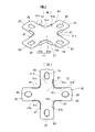
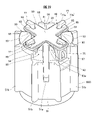
- FIG. 1 It is an exploded perspective view which shows 1st Embodiment of the valve device for a fuel tank which concerns on this invention. It is sectional drawing in the state which the float valve is lowered and the ventilation hole is opened in the valve device. It is a perspective view of the lower member constituting the float valve of the valve device.
- the upper member constituting the float valve is shown, (a) is an enlarged perspective view thereof, and (b) is a bottom view.
- the elastic seal member constituting the float valve is shown, (a) is an enlarged perspective view thereof, and (b) is a plan view. It is a perspective view of the float valve. It is a front view of the float valve.
- FIG. 9 is a cross-sectional view taken along the line AA of FIG. It is sectional drawing in the state which the float valve rises without tilting in the valve device, and the ventilation hole is closed. It is sectional drawing in the state which the float valve tilted up and closed the ventilation hole in the valve device. It is sectional drawing of the state when the float valve tries to go down from the state which the float valve closed a ventilation hole in the valve device.
- FIG. 3 is a cross-sectional view of a state in which the float valve is further lowered from the state shown in FIG. 13 to open a ventilation hole.
- a second embodiment of the fuel tank valve device according to the present invention is shown, (A) is a perspective view of an elastic seal member constituting the float valve, and (B) is a front view of the elastic seal member. .. It is a top view of the float valve in a state where an elastic seal member is prevented from coming off and held by a lower member.
- a third embodiment of the fuel tank valve device according to the present invention is shown, and is a perspective view of the float valve thereof.
- a fourth embodiment of the fuel tank valve device according to the present invention is shown, and is a perspective view of the float valve thereof.
- a fifth embodiment of the fuel tank valve device according to the present invention is shown, and is a perspective view of the float valve thereof. It is a perspective view of the lower member constituting the float valve. It is a top view of the lower member constituting the float valve. It is a side view of the float valve. It is an enlarged perspective view of the main part of the float valve.
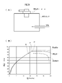
- a test for confirming the degree of blow-up of the valve device is shown, (A) is a schematic explanatory view of the test method, and (B) is the test result, and is a graph showing the relationship between pressure and flow rate.
- fuel means liquid fuel (including droplets of fuel)
- fuel vapor means evaporated fuel
- the valve device 10 in this embodiment has a housing 15 having a valve chamber V and a ventilation chamber R, and a float valve 40 arranged so as to be able to move up and down in the valve chamber V. ing.
- the float valve 40 has a lower member 50, an upper member 60 arranged above the lower member 50, and an elastic sealing member 80 held by the upper member 60.
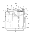
- the housing 15 has a substantially tubular shape, has a housing main body 20 having a partition wall 23 above, an upper cover 30 mounted above the housing main body 20, and is mounted below the housing main body 20. It has a lower cap 35.
- the housing body 20 has a substantially cylindrical peripheral wall 21, and a partition wall 23 is arranged above the peripheral wall 21.
- a plurality of through openings 21a and a locking protrusion 21b are formed above the peripheral wall 21, and a locking hole 21c is formed below the peripheral wall 21.
- the flange portion 24 projects from the upper side of the peripheral wall 21.
- a round hole-shaped ventilation hole 25 is formed in the central portion of the partition wall 23.
- a cylindrical wall 27 is projected from the upper surface side of the partition wall 23 and from the outside of the ventilation hole 25, and a seal ring 28 is attached to the outer periphery thereof. It has become so.
- the lower cap 35 has a plurality of through openings 36, and a plurality of locking claws 37 are formed on the outer periphery thereof.
- a valve chamber V communicating with the inside of the fuel tank (not shown) is formed below the housing through the partition wall 23 (see FIG. 2).
- a float valve 40 that opens and closes the ventilation hole 25 is located between the lower cap 35 and the float valve urging spring S (hereinafter, simply “urging spring S”) formed of a coil spring. It is designed to be accommodated and arranged so that it can be raised and lowered with the intervention of).
- the float valve 40 rises due to its own buoyancy and the urging force of the urging spring S when the fuel is immersed, and descends by its own weight when the fuel is not immersed.
- the upper cover 30 has a peripheral wall 31 extending at a predetermined height, a ceiling portion 32 closing above the peripheral wall 31, and a flange portion extending in an annular shape from the middle of the extending direction of the peripheral wall 31. It has 33 and.
- a vent 31a (see FIG. 2) is formed at a predetermined position on the peripheral wall 31, and a fuel vapor pipe 34 having a substantially cylindrical shape extends outward from the outer peripheral edge of the vent 31a.
- a tube (not shown) that communicates with a canister or the like arranged outside the fuel tank (not shown) is connected to the fuel vapor pipe 34.
- a frame-shaped locking piece 31b that is locked to the locking protrusion 21b of the housing main body 20 is vertically hung from the lower end surface of the peripheral wall 31.
- the upper cover 30 is covered from above the housing body 20, and the peripheral wall 31 of the upper cover 30 and the tubular wall 27 of the housing body 20 are covered. Then, the seal ring 28 is sandwiched. At the same time, the upper cover 30 is attached to the housing body 20 by locking the locking piece 31b of the upper cover 30 to the locking protrusion 21b of the housing body 20. As a result, a ventilation chamber R communicating with the outside of the fuel tank is formed above the partition wall 23 (see FIG. 2).
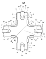
- a valve seat 25b communicating with the ventilation hole 25 is provided on the valve chamber V side of the partition wall 23. That is, as shown in FIG. 2, the protruding wall portion 25a communicating with the ventilation hole 25 protrudes downward from the back side (valve chamber V side) peripheral edge of the ventilation hole 25 formed in the central portion of the partition wall 23. There is. The lower peripheral edge of the protruding wall portion 25a is surrounded by a valve seat 25b having a substantially cross-shaped frame. The valve seat 25b communicates with the ventilation hole 25, and the elastic sealing member 80 comes into contact with and separates from the valve seat 25b.
- the lower member 50 constituting the float valve 40 has a peripheral wall 51 extending in the vertical direction with a predetermined length and a ceiling wall 53 arranged above the peripheral wall 51, and has a substantially cylindrical shape with an opening at the bottom and a closure at the top. ing.
- a pair of guide grooves 51a and 51a extending in the axial direction from the ceiling wall 53 toward the lower side of the peripheral wall are formed at two locations facing the peripheral wall 51 in the circumferential direction.
- Guide ridges (not shown) provided on the inner circumference of the housing body 20 are inserted into these guide grooves 51a and 51a to guide the float valve 40 up and down.
- a plurality of guide ribs 51b extending radially are extended along the axial direction. These guide ribs 51b are arranged to face the inner circumference of the peripheral wall 21 of the housing main body 20 and form an elevating guide for the float valve 40.
- a support protrusion 53a having a curved outer surface is projected from the center of the surface (also referred to as "upper surface”; the same applies in the following description) side of the ceiling wall 53.
- a plate-shaped portion 61 of the upper member 60 is placed on the support protrusion 53a to swingably support the upper member 60.
- a pair of through holes 53b are formed in the ceiling wall 53 in the vertical direction and communicates with the internal space of the lower member 50.
- the outer peripheral edge portion of the ceiling wall 53 is cut by a pair of cut portions 55a, 55a and also by another pair of cut portions 55b, 55b orthogonal to the pair of cut portions 55a, 55a.
- flat surface portions 55c, 55c cut into a flat surface shape are formed at positions of the peripheral wall 51 that match the pair of cut portions 55b, 55b.
- a retaining protrusion 57 having a tapered surface 57a on the upper outer surface is projected.
- the retaining protrusion 57 has a constant axial length (when the float valve 40 is viewed from the front direction (when the float valve 40 is viewed from a direction orthogonal to the axial direction)). It has a substantially rectangular shape formed with a constant circumferential width (horizontal width) and a vertical length).
- the retaining protrusion 57 is slidable along the axial direction Z (see FIG. 6) of the float valve 40 in the retaining hole 75a provided in the upper member 60, and is in the width direction of the float valve 40. It is movably inserted along Y (see FIG. 6).
- the retaining protrusion 57 is one of the "first retaining portions" in the present invention that holds the upper member 60 swingably with respect to the lower member 50.
- the shape and structure of the lower member are not limited to the above mode as long as there is a portion forming the first retaining portion as described above.
- the upper member 60 is arranged above the lower member 50 so as to be swingably held by the lower member 50 via the first retaining portion.
- the upper member 60 of this embodiment has a plate-shaped portion 61 that is arranged between the lower member 50 and the elastic seal member 80 and is formed with a predetermined thickness.
- the plate-shaped portion 61 has a central portion 63 and a plurality of extending portions 65 extending outward from the central portion 63.
- the plate-shaped portion 61 of this embodiment has a shape suitable for the plate-shaped portion 61 so as to be able to receive and support the elastic sealing member 80 having a substantially cross shape as a whole. That is, in this plate-shaped portion 61, four extending portions 65 extend radially outward from the central portion 63, and the extending portions 65 and 65 adjacent to each other in the circumferential direction are orthogonal to each other. It has a substantially cross shape as a whole.
- each extending portion 65 the base portion 65a close to the central portion 63 is wide, and the tip portion 65b separated from the central portion 63 is formed to be narrower than the base portion 65a. Further, there is a notch between one side edge of the base portion 65a of the predetermined extension portion 65 and one side edge of the base portion 65a of the extension portion 65 adjacent to the extension portion 65 in the circumferential direction. 67 is formed. That is, although the plate-shaped portion 61 of the upper member 60C in the fourth embodiment shown in FIG. 18 does not have such a cutout portion 67, the plate-shaped portion 61 of the first embodiment has an outer periphery thereof. A notch portion 67 is formed by notching a part of the above.
- the outer peripheral shape of the plate-shaped portion 61 of the upper member 60 has a shape substantially matching the outer peripheral shape of the elastic seal member 80 having a substantially cross shape.
- a concave portion 69 recessed in a curved surface shape is formed on the base portion 65a side of the central portion 63 of the plate-shaped portion 61 and each extending portion 65, and on the surface side thereof (elastic sealing member 80 side).
- the concave portion 69 has a substantially mortar shape having a gently curved surface shape so as to gradually deepen from a predetermined position of the base portion 65a of each extending portion 65 toward the center of the central portion 63.
- the recess 69 is a portion that allows the bending deformation when the sealing portion 81 described later of the elastic sealing member 80 abuts on the valve seat 25b and bends and deforms so as to be convex downward (FIG. FIG. 11).
- the plate-shaped portion 61 may have a plate-shaped portion having a constant thickness without providing the recess 69 as described above.
- the outer peripheral 71 of the upper member 60 has the following shape. That is, as shown in FIG. 4B, when the upper member 60 is viewed from the axial direction of the float valve 40, the outer peripheral portion 71 of the plate-shaped portion 61 is thicker than the lower portion 71a in the thickness direction.
- the upper portion 71b of is formed to be larger.
- the lower portion 71a in the thickness direction of the plate-shaped portion 61 means a portion facing the lower member 50 side, and the upper portion in the thickness direction of the plate-shaped portion 61 means a portion facing the elastic seal member 80 side.
- the outer peripheral portion 71 of the plate-shaped portion 61 is provided with an inclined surface 73 whose diameter increases from the lower portion 71a in the thickness direction toward the upper portion 71b.
- the outer peripheral 71 of the plate-shaped portion 61 in this embodiment has a gently curved inclined surface 73 that gradually expands in diameter from the lower side to the upper side in the thickness direction.
- the outer peripheral portion 71 of the plate-shaped portion 61 has a shape in which the upper portion 71b gradually expands more than the lower portion 71a in the thickness direction (FIG. 4 (B). )reference).
- the outer peripheral 71 of the plate-shaped portion 61 may have a stepped surface instead of the inclined surface 73, and may have a shape in which the upper portion 71b is larger than the lower portion 71a.
- the plate-shaped portion 61 is a pair of extending portions 65, 65 arranged so as to face each other with the central portion 63 interposed therebetween, from the most advanced back side (lower member 50 side) of the tip portions 65b, 65b.
- the retaining pieces 75 and 75 are vertically installed.
- Each retaining piece 75 is formed with an elongated retaining hole 75a extending along the axial direction of the float valve 40.
- the retaining hole 75a is substantially formed with a constant axial length (vertical length) and a constant circumferential width (horizontal width) when the float valve 40 is viewed from the front direction. It has a rectangular shape.
- the retaining hole 75a is formed to be longer than the axial length of the retaining protrusion 57 provided on the lower member 50 side and wider than the circumferential width of the retaining protrusion 57.
- the upper member 60 can swing with respect to the lower member 50 by inserting each retaining protrusion 57 into the retaining hole 75a of each retaining piece 75 from the inside. It is designed to be held in place.
- the upper member 60 refers to the lower member 50 in the radial direction X of the float valve 40 via the first retaining portion (see FIG. 6). It is possible to move a predetermined distance along the width direction Y orthogonal to the above, and to move a predetermined distance along the axial direction Z of the float valve 40. Further, as shown in FIG. 8, the upper member 60 is relative to the lower member 50. It is possible to swing.
- the retaining protrusion 57 is locked to the inner surfaces of both ends of the retaining hole 75a in the longitudinal direction.
- the retaining protrusion 57 is locked to the inner surfaces of both sides of the retaining hole 75a in the width direction, so that the upper member 60 is prevented from coming off from the lower member 50. Be retained.
- the retaining protrusion 57 on the lower member 50 side and the retaining hole 75a of the retaining piece 75 on the upper member 60 side form the "first retaining portion" in the present invention. There is.
- Each retaining hook 77 has a shaft portion 77a that is loosely fitted in the retaining hole 85, and an overhanging portion 77b that protrudes from the upper end of the shaft portion 77a from the inner peripheral edge of the retaining hole 85.
- the shaft portion 77a has a square columnar shape.
- the shaft portion 77a is formed to be shorter than the axial length of the retaining hole 85 and narrower than the width of the retaining hole 85 orthogonal to the axial direction, and is formed to play in the retaining hole 85. It is designed to fit. That is, the shaft portion 77a can move along the radial direction X (see FIG. 6) of the float valve 40 in the retaining hole 85 of the elastic seal member 80, and along the width direction Y of the float valve 40. It is designed to be movable.
- the overhanging portion 77b extends from the upper end of the shaft portion 77a toward the tip end portion 65b of the extending portion 65 (see FIG. 4B), and is slightly higher than the tip end portion 65b. It overhangs to a position where it protrudes outward (see FIG. 9).
- the overhanging portion 77b of this embodiment is adapted to overhang from the inner peripheral edge of the retaining hole 85 on the outer diameter side (see FIG. 9). Further, as shown in FIG. 7, a gap larger than the thickness of the elastic sealing member 80 is formed between the extending portion 65 and the extending portion 77b.
- the lower member can be oscillatedly held by the lower retaining portion via the first retaining portion, and the elastic seal member can be oscillated via the second retaining portion. As long as it can be held in place, it is not limited to the above mode.
- first retaining portion for example, a retaining piece having a retaining hole is provided on the lower member side, and the retaining piece is inserted into the retaining hole on the upper member side and the retaining hole is also provided.
- a retaining protrusion that can move in the circumferential direction and the axial direction may be provided inside, and is not particularly limited as long as the upper member can swing and hold the retaining protrusion with respect to the lower member.
- the elastic sealing member 80 having elasticity for opening and closing the ventilation hole 25 will be described.
- the elastic sealing member 80 of this embodiment has a sealing portion 81 that is brought into contact with and separated from the valve seat 25b.
- the seal portion 81 has a central portion 81a and a plurality of side portions 81b extending outward from the central portion 81a.
- the seal portion 81 of this embodiment corresponds to the valve seat 25b having a substantially cross-shaped frame shape, and the four side portions 81b extend radially outward from the central portion 81a and in the circumferential direction.
- the side portions 81b and 81b adjacent to each other are orthogonal to each other, and the seal portion 81 has a substantially cross shape.
- a rounded R-shaped portion 81c is formed at a corner between the side portions 81b and 81b adjacent to each other in the circumferential direction.
- the extending portion 83 extends outward. That is, it has four extending portions 83 that extend radially with respect to the sealing portion 81, and the extending portions 83 and 83 that are adjacent to each other in the circumferential direction are orthogonal to each other, and as a result, the elastic seal is provided.
- the member 80 has a substantially cross shape as a whole.
- the seal portion 81 and each extension portion 83 are flush with each other (the surface of the seal portion 81 and the surface of each extension portion 83 are present on the same plane).
- Each extending portion 83 is formed with a retaining hole 85 having a substantially elongated hole shape, which extends long along the extending direction.
- Each retaining hole 85 has a shape in which both ends in the longitudinal direction are rounded. Further, the shaft portion 77a of the retaining hook 77 provided in the upper member 60 is freely inserted into each retaining hole 85.
- each retaining hole 85 has an axial length longer than the axial length of the shaft portion 77a and a width orthogonal to the axial direction. , Is formed wider than the width of the shaft portion 77a.
- each retaining hook 77 is inserted into each retaining hole 85, and the overhanging portion 77b is positioned on the front peripheral edge of each retaining hole 85.
- the elastic seal member 80 is held so as to be able to move a predetermined distance with respect to the upper member 60.
- a predetermined gap is provided between both ends of the retaining hole 85 in the axial direction and both ends of the shaft portion 77a in the axial direction. Is formed, and a predetermined gap is also formed between both sides of the retaining hole 85 in the width direction and both sides of the shaft portion 77a in the width direction.
- the extending portion 83 is arranged in the gap between the extending portion 65 and the overhanging portion 77b of the upper member 60.
- the elastic seal member 80 is predetermined with respect to the upper member 60 along the radial direction X of the float valve 40 via the second retaining portion. It can move a predetermined distance, can move a predetermined distance along the width direction Y of the float valve 40, and can move a predetermined distance along the axial direction Z of the float valve 40.
- the shaft portion 77a is locked to the inner surfaces of both ends in the axial direction of the retaining hole 85.
- the shaft portion 77a moves to the maximum along the width direction Y, the shaft portion 77a is locked to the inner surfaces on both sides of the retaining hole 85 in the width direction, and (3) when the shaft portion 77a moves to the maximum in the axial direction Z. Since the overhanging portion 77b is locked to the front peripheral edge of the retaining hole 85, the elastic sealing member 80 is held by the upper member 60 to prevent it from coming off.
- the retaining hook 77 on the upper member 60 side and the retaining hole 85 on the elastic seal member 80 side form the "second retaining portion" in the present invention.
- the elastic seal member 80 has a shape that does not protrude from the outer periphery of the upper member 60 even if it moves to the maximum with respect to the upper member 60.
- the elastic seal member 80 in this embodiment has a substantially cross shape that matches the shape of the plate-shaped portion 61 having a substantially cross shape of the upper member 60, and has a substantially cross shape with respect to the entire circumference of the plate-shaped portion 61 of the upper member 60. Therefore, the entire circumference of the elastic seal member 80 is one size smaller and has a similar shape.
- the outer circumference of the seal portion 81 of the elastic seal member 80 is larger than the outer circumference of the plate-shaped portion 61 of the upper member 60. It is formed so as to be located inside, and the outer periphery of each extension portion 83 of the elastic seal member 80 is formed so as to be located inside the outer periphery of each extension portion 65 of the upper member 60.
- the area of the elastic seal member 80 is smaller than the area of the plate-shaped portion 61 of the upper member 60. Is formed in.
- the elastic sealing member 80 moves to the maximum with respect to the upper member 60 along the width direction Y of the float valve 40 (the imaginary line in the left-right direction in FIG. 9).
- the elastic sealing member 80 is the plate-shaped portion 61 of the upper member 60 even when the float valve 40 is moved to the maximum along the radial direction X (see the imaginary line in the vertical direction in FIG. 9). It is designed so that it does not protrude from the outer circumference of the.
- the movement of the elastic seal member 80 with respect to the upper member 60 is restricted by the shaft portion 77a of the retaining hook 77 and the retaining hole 85 forming the second retaining portion described above.
- a reinforcing rib 87 for reinforcing the seal portion 81 is provided on the outer edge portion of the seal portion 81.
- Reinforcing ribs 87 having a substantially L-shaped bead shape stand toward the front side and the back side of the seal portion 81 over the outer edge portion of the R-shaped portion 81c provided between the side portions 81b and 81b. It is set up.
- the vertical direction of the reinforcing rib 87 is perpendicular to the surface direction of the plate-shaped elastic sealing member 80. Further, the reinforcing rib 87 does not surround the entire circumference of the elastic sealing member 80, and both ends in the extending direction are open ends. In this embodiment, reinforcing ribs 87 are provided at the four corners of the substantially cross-shaped seal portion 81.
- all the parts such as the sealing portion 81, the plurality of extending portions 83, and the reinforcing ribs 87 are integrally formed from an elastic material such as rubber or an elastic elastomer. ..
- the elastic sealing member may have a shape in which three extending portions radiate from the outer periphery of the sealing portion, and each extending portion may be provided with a retaining hole. In this case, three retaining portions are arranged so as to surround the seal portion.
- the elastic sealing member may have a long plate shape in which a pair of extending portions extend from both sides of the sealing portion, and each extending portion may be provided with a retaining hole. In this case, the retaining portions are arranged on both sides of the sealing portion with the sealing portion interposed therebetween.
- three or more retaining portions may be provided so as to surround the sealing portion, and for example, five or six may be provided.
- the shape and structure of the elastic seal member is limited to the above mode as long as it can be oscillatedly held by the upper member via the second retaining portion and can be brought into contact with and detached from the valve seat. It is not something that will be done.
- the sealing portion of the elastic sealing member for example, the sealing portion may have a disk shape, an elliptical shape, an oval shape, or a square shape such as a quadrangle, a pentagon, or a hexagon. It suffices if it can be attached to and detached from.
- the shape and structure of the above-mentioned "second retaining portion" itself may be other than the above-mentioned retaining hook and retaining hole, and the elastic sealing member can be moved by a predetermined distance with respect to the upper member. As long as it can be held in place, it is not particularly limited.
- the vehicle turns a curve, runs on an uneven road or a slope, or falls down due to an accident, and the fuel in the fuel tank violently swings and the fuel liquid level rises.
- the float valve 40 rises due to the buoyancy of the float valve 40 itself.
- the sealing portion 81 of the elastic sealing member 80 abuts on the valve seat 25b and closes the ventilation hole 25.
- the seal portion 81 having a substantially cross shape bends and deforms so as to be convex downward, and the surface side thereof abuts on the valve seat 25b.
- the ventilation hole 25 is closed.
- the back surface side of the seal portion 81 that is bent and deformed so as to be convex downward comes into close contact with the surface of the recess 69 of the plate-shaped portion 61 of the upper member 60.
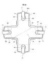
- the float valve 40 rises straight without tilting with respect to the axial direction of the housing 15, but as shown in FIG. 12, the float valve 40 is the shaft of the housing 15. In some cases, it tilts with respect to the direction and rises.
- the seal portion 81 of the elastic seal member 80 since the inclination of the seal portion 81 of the elastic seal member 80 is corrected, the seal portion 81 can be brought into contact with the valve seat 25b without inclination, and the seal with respect to the valve seat 25b can be brought into contact with the valve seat 25b. The sealing property of the portion 81 can be ensured.
- the float valve 40 is lowered by its own weight. Then, as shown in FIG. 13, the lower member 50 descends by a predetermined distance with respect to the seal portion 81 that is in contact with and attached to the valve seat 25b, and the retaining hole 75a of the retaining piece 75 of the upper member 60 is provided. The retaining protrusion 57 of the lower member 50 descends inside, and the retaining protrusion 57 is locked to the inner surface of the lower end of the retaining hole 75a.
- the load of the lower member 50 acts on the upper member 60, and the shaft portion 77a of the retaining hook 77 of the upper member 60 descends in the retaining hole 85 of the elastic sealing member 80 to prevent the retaining hole.
- the overhanging portion 77b of the retaining hook 77 is engaged with the front peripheral edge of the 85.
- the load of the lower member 50 acts on the extension portion 83 of the elastic seal member 80 via the upper member 60 (the load of the lower member 50 and the upper member 60 acts on the extension portion 83).
- the extension portion 83 of the elastic seal member 80 is elastically deformed so as to be pulled diagonally downward, and the extension portion 83 moves along the axial direction Z and the radial direction X of the float valve 40. ..
- the side portion 81b of the seal portion 81 which is continuously provided to the extension portion 83, gradually separates from the proximal end side with respect to the valve seat 25b, and then, as shown in FIG.
- the ventilation hole 25 can be completely opened.
- the restart valve pressure of the float valve 40 can be improved.
- "improving the restart valve pressure” means the performance that the float valve can be easily peeled off from the valve seat and the ventilation hole can be opened even when the tank internal pressure is high. Further, as the seal portion 81 is peeled off from the valve seat 25b, the entire float valve 40 is lowered.
- the upper member 60 is held so as to be swingable with respect to the lower member 50, so that even if the float valve 40 rises in an inclined state, the elastic seal is provided.
- the member 80 can be brought into contact with the valve seat 25b without tilting (see FIG. 12), and the sealing property of the elastic sealing member 80 with respect to the valve seat 25b can be ensured.
- the elastic seal member 80 is held so as to be movable with respect to the upper member 60 by a predetermined distance, when the float valve 40 descends after the elastic seal member 80 comes into contact with the valve seat 25b, the float valve 40 is lowered.
- the upper member 60 moves with respect to the elastic seal member 80 attached to the valve seat 25b, and the weight of the float valve 40 acts on the elastic seal member 80, making it easy to peel off the elastic seal member 80 from the valve seat 25b. (See FIGS. 13 and 14), the restart valve pressure of the float valve 40 can be improved.
- the elastic seal member 80 has a shape that does not protrude from the outer periphery of the upper member 60 even if it moves to the maximum with respect to the upper member 60.
- the elastic seal member 80 has a shape that does not protrude from the outer periphery of the upper member 60 even if it moves to the maximum with respect to the upper member 60, so that it is difficult for the gas to collide with the elastic seal member 80. And suppresses the flow so as to enter the back side of the elastic seal member 80 and push up the seal portion 81, and the seal portion 81 bends upward so as to form a convex curved surface as shown by the imaginary line in FIG. It can be prevented from deforming. Therefore, it is possible to prevent the float valve 40 from rising so as to be lifted by the gas via the elastic seal member 80, and it is possible to make it difficult for the float valve 40 to blow up.
- the outer peripheral portion 71 of the plate-shaped portion 61 is a lower portion in the thickness direction.
- the upper portion 71b is formed to be larger than the 71a.
- the gas flowing into the valve chamber V flows from the lower portion to the upper portion of the outer peripheral 71 of the upper member 60 in the thickness direction, as shown by the arrow F2 in FIG. Since the gas is guided to the outside of the elastic seal member 80, it is possible to make it difficult for the gas to hit the elastic seal member 80. Further, even if the outer circumference of the upper member 60 is made smaller so as to be along the outer circumference of the elastic seal member 80, it is possible to make it difficult for the gas to hit the elastic seal member 80.
- the outer peripheral 71 of the plate-shaped portion 61 is provided with an inclined surface 73 whose diameter increases from the lower portion to the upper portion in the thickness direction. Therefore, when the internal pressure of the fuel tank rises, the gas flowing into the valve chamber V flows while being guided by the inclined surface 73 of the upper member 60 as shown by the arrow F2 in FIG. 10, and flows outward of the elastic sealing member 80. Therefore, the gas can be made hard to hit by the elastic sealing member 80.
- the elastic seal member 80 has a seal portion 81 that comes into contact with and separates from the valve seat 25b, and is the second retaining portion arranged on both sides of the seal portion 81 with the seal portion 81 interposed therebetween? Or, three or more are arranged so as to surround the seal portion 81 (here, four retaining holes 85 forming the second retaining portion are arranged so as to surround the sealing portion 81).
- a reinforcing rib 87 for reinforcing the seal portion 81 is provided on the outer edge portion of the portion 81 (see FIG. 5).
- the reinforcing rib 87 for reinforcing the seal portion 81 is provided on the outer edge portion of the seal portion 81, after the seal portion 81 comes into contact with the valve seat 25b when the float valve 40 is raised. Since the extension portion 83 is pulled by the upper member 60 and peels off in a plate shape while maintaining rigidity, the restart valve pressure of the float valve 40 can be further improved.
- the second retaining portion includes a retaining hole 85 formed in the elastic seal member 80 and a retaining hook 77 inserted into the retaining hole 85, and the retaining hook 77.
- the overhanging portion 77b protrudes from the inner peripheral edge of the hole, so that the elastic sealing member 80 Can be easily attached to the upper member 60, and can be reliably prevented from coming off. Further, the movement performance of the elastic sealing member 80 with respect to the upper member 60 can be ensured by the shaft portion 77a loosely fitted in the retaining hole 85.
- (Second embodiment of the valve device) 15 and 16 show a second embodiment of the valve device according to the present invention.
- the same parts as those in the embodiment are designated by the same reference numerals, and the description thereof will be omitted.
- the shape of the elastic seal member 80A of the valve device in this embodiment is different from that of the embodiment. That is, the elastic seal member 80A has a shape without reinforcing ribs on the outer edge portion of the seal portion 81. Further, as shown in FIGS. 15A and 15B, in the elastic sealing member 80A, when the sealing portion 81 comes into contact with the valve seat 25b, a plurality of extending portions 83 are provided with respect to the sealing portion 81. It has a slanted shape. That is, in the elastic seal member 80A, when the seal portion 81 abuts on the valve seat 25b, the center of the seal portion 81 is the lowest, and the extension portion 83 gradually increases toward the tip in the extension direction. It has a slanted shape.
- the elastic sealing member 80A of this embodiment has a shape without reinforcing ribs on the outer edge portion of the sealing portion 81, a plurality of extending portions are formed when the sealing portion 81 comes into contact with the valve seat 25b.
- the 83 is easily deformed into a shape inclined with respect to the seal portion 81 as shown in FIGS. 15A and 15B, and when the elastic seal member 80A is moved, the outer periphery of each extension portion 83 is formed. It is possible to prevent the upper member 60 from protruding from the outer peripheral portion 71, and it is possible to further improve the sealing property of the sealing portion 81 with respect to the valve seat 25b.
- FIG. 17 shows a third embodiment of the valve device according to the present invention.
- the same parts as those in the embodiment are designated by the same reference numerals, and the description thereof will be omitted.
- the shape of the lower member 50B of the valve device in this embodiment is different from that in the embodiment.
- the outer peripheral edge portion of the ceiling wall 53 of the lower member 50B is provided with four raised portions 59 that enter into the four notched portions 67 formed in the elastic seal member 80.
- the four raised portions 59 two raised portions 59, 59 are arranged at positions consistent with the pair of guide grooves 51a, 51a of the lower member 50B, and the remaining two raised portions 59, 59 are It is arranged at a position orthogonal to the two raised portions 59 and 59.
- each raised portion 59 has a pair of side surfaces 59a and 59a orthogonal to each other and a curved side surface 59b connecting these side surfaces 59a and 59a, and has a shape raised at a predetermined height. ing.
- Each side surface 59a is arranged so as to face the side surface of the extension portion 65 of the upper member 60 and the side surface of the extension portion 83 of the elastic seal member 80.
- FIG. 18 shows a fourth embodiment of the valve device according to the present invention.
- the same parts as those in the embodiment are designated by the same reference numerals, and the description thereof will be omitted.
- the shape of the upper member 60C of the valve device in this embodiment is different from that in the embodiment.
- the upper member 60C has one side edge of the base portion 65a of the predetermined extension portion 65 and the circumferential direction with respect to the extension portion 65.
- One side edge of the base portion 65a of the extension portion 65 adjacent to the above is connected by the connecting portion 67a.
- a wall portion 68 having a predetermined width is erected from the front outer peripheral edge portion of each connecting portion 67a.
- the wall portion 68 is arranged at a position facing the reinforcing rib 87 of the elastic seal member 80 in a state where the elastic seal member 80 is held by the upper member 60C so as not to come off.
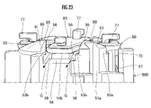
- (Fifth Embodiment of the valve device) 19 to 23 show a fifth embodiment of the valve device according to the present invention.
- the same parts as those in the embodiment are designated by the same reference numerals, and the description thereof will be omitted.
- the shape of the lower member 50D of the valve device in this embodiment is different from that in the embodiment.
- the lower member 50D of this embodiment has a ceiling wall 53 provided with a mounting surface 54 on which the upper member 60 is mounted.
- the above-mentioned mounting surface 54 extends radially outward from the substantially circular central surface 54 réelle arranged in the radial center portion of the ceiling wall 53 and the peripheral edge of the central surface 54 réelle. It is composed of a plurality of outward extending surfaces 54b.
- the mounting surface 54 in this embodiment has four outward extending surfaces 54b arranged at intervals of 90 degrees with respect to the center of the mounting surface, and corresponds to the upper member 60 having a substantially cross shape. It is roughly cross-shaped.
- the upper surfaces of the central surface 54rion and each outward extending surface 54b are flat surfaces having a constant height without unevenness.
- the support protrusion 53 Given projects from the center of the central surface 54rion on the surface side, and the upper member 60 is swingably supported by the support protrusion 53rion.
- the "mounting surface" in the present invention is located below the upper member, and when the upper member swings in either direction, it abuts on the back surface of the upper member to receive and support the upper member. It means that it is a part that can be placed (placed).
- a pair of outward extending surfaces 54b, 54b arranged on a straight line passing through the center of the mounting surface are extended.
- the protruding tip portion extends to the flat surface portion 55c located on the outer periphery of the lower member 50D, but is orthogonal to the pair of outward extending surfaces 54b and 54b, and the other pair of outward extending surfaces 54b and 54b.
- the tip portion in the extending direction does not extend to the outer periphery of the lower member 50D.
- the ceiling wall 53 has a plurality of outer circumferences arranged on the outer periphery of the ceiling wall 53 so as to be located between the adjacent outward extending surfaces 54b, 54b by providing the mounting surface 54 as described above. It has an arrangement portion 53b.
- the ceiling wall 53 of this embodiment has four outer peripheral arrangement portions 53b. Specifically, a pair of outer peripheral arrangement portions 53b, 53b are arranged at locations facing each other in the radial direction with the radial center portion of the ceiling wall 53 interposed therebetween, and the pair of outer peripheral arrangement portions 53b, 53b are arranged. A pair of outer peripheral arrangement portions 53b, 53b are arranged orthogonal to each other (see FIG. 21). Of these four outer peripheral arrangement portions 53b, the pair of outer peripheral arrangement portions 53b and 53b arranged to face each other are arranged at positions consistent with the pair of guide grooves 51 réelle and 51 réelle provided in the lower member 50D (FIG. 20). reference).
- each outer peripheral arrangement portion 53b has a substantially fan shape having a pair of side edge portions 53c and 53c orthogonal to each other when the lower member 50D is viewed from the axial direction.
- a groove 56 is formed between the edge portion 54c and the edge portion 54c.
- the lower member 50D in this embodiment has a mounting surface facing outward of the lower member 50D on a portion of the ceiling wall 53 other than the mounting surface 54 when viewed from the axial direction of the float valve 40.
- An inclined surface 58 is formed which is inclined so as to be lower than 54.
- the radial center portion of the ceiling wall 53 is the highest on the bottom surface of the groove portion 56, and the height gradually decreases toward the radial outward side of the float valve 40.
- the inclined surface 58 having an inclined and tapered surface shape is formed. Further, an inclined surface 58 having a tapered surface shape is also formed in a portion of the mounting surface 54 between the tip of the predetermined outward extending surface 54b in the extending direction and the outer periphery of the lower member 50D. ..
- the inclined surface may be, for example, a curved surface recessed downward, a curved surface convex upward, formed from a plurality of tapered surfaces having different inclination angles, or a stepped surface.
- the shape may be inclined so as to be lower than the mounting surface toward the outside of the lower member as a whole.
- the lower member 50D protrudes from the mounting surface 54 between the adjacent second retaining portions (the retaining hook 77 on the upper member 60 side and the retaining hole 85 on the elastic seal member 80 side). , The protrusion 90 is formed.
- the protruding portion 90 protrudes from the upper surface of each outer peripheral arrangement portion 53b of the ceiling wall 53. That is, a pair of projecting portions 90, 90 are arranged at locations facing each other in the radial direction with the central portion in the radial direction of the ceiling wall 53 interposed therebetween, and at the same time, orthogonal to the pair of projecting portions 90, 90. , Another pair of protrusions 90, 90 are arranged. Of these four protrusions 90, the pair of protrusions 90 and 90 arranged so as to face each other in the radial direction are arranged at positions consistent with the pair of guide grooves 51 réelle and 51 réelle provided in the lower member 50D (FIG. 21).
- each protruding portion 90 has a pair of side surfaces 91 and 91 orthogonal to each other, and also has a protruding end surface 93 provided between the side surfaces 91 and 91. It is a protrusion having a substantially fan shape when the lower member 50D is viewed from the axial direction in accordance with the above-mentioned outer peripheral arrangement portion 53b.
- the pair of protrusions 90, 90 arranged at positions consistent with the pair of guide grooves 51 réelle, 51 réelle of the lower member 50D are radially outward of the lower member 50D. It has an outer peripheral surface 93 réelle erected from the outer peripheral arrangement portion 53b of the ceiling wall 53.
- the other pair of projecting portions 90, 90 has a shape in which the outer peripheral edge portion of the projecting end surface 93 is connected to the upper surface of the outer peripheral arrangement portion 53b of the ceiling wall 53, and the outer peripheral surface 93 réelle as described above does not have. ing.
- the protruding end surface 93 of the protruding end surface 90 projects so that the inner corner portion of the ceiling wall 53 facing the radial center portion is the highest from the upper surface of the ceiling wall 53. (It can also be called the "top").
- the protruding end surface 93 of this embodiment draws a curved surface that is slightly convex toward the outside from the protruding end portion 95 toward the outside of the lower member 50D, and the protrusion height gradually decreases. In addition, it has an inclined shape.
- the protruding end portion 95 of the protruding portion 90 protrudes from the upper surface 60 réelle of the upper member 60 in a state where the upper member 60 is mounted on the mounting surface 54. Further, the protruding end portion 95 in this embodiment also protrudes from the upper surface 80 réelle of the elastic sealing member 80 (see FIG. 22).
- the outer peripheral edges of the protruding end faces 93 and 93 of the pair of protruding portions 90 and 90 arranged at positions consistent with the pair of guide grooves 51 réelle and 51 réelle of the lower member 50D are paired with each other.
- the position is higher than the outer peripheral edge of the protruding end faces 93, 93 of the protruding portions 90, 90.
- the protruding end surface may be, for example, a tapered surface, a curved surface recessed downward, formed from a plurality of tapered surfaces having different inclination angles, or a stepped surface. It suffices as long as it has a shape that inclines toward the outside of the lower member as a whole.
- the protrusions include, for example, triangles, quadrangles, rhombuses, trapezoids, polygonal protrusions having a pentagonal shape or more, and circular, oval, and oval protrusions. It may be a department, and is not particularly limited.
- the lower member 50D has a ceiling wall 53 provided with a mounting surface 54 on which the upper member 60 is mounted, and the lower member 50D is further mounted on the lower member 50D from the axial direction of the float valve 40.
- an inclined surface 58 is formed on a portion of the ceiling wall 53 other than the mounting surface 54 so as to be inclined toward the outside of the lower member 50D so as to be lower than the mounting surface 54.
- the fuel is collected by the inclined surface 58 of the lower member 50D. It is possible to facilitate the discharge to the outside, and it is possible to suppress the inflow of fuel from the ventilation hole 25 into the ventilation chamber R.
- the fuel flows down to the groove portion 56 and flows on the inclined surface 58 on the bottom surface of the groove portion 56. , Is discharged to the outside of the lower member 50D.
- the inclined surface 58 provided in that portion. Is discharged to the outside of the lower member 50D.
- the inclined surface 58 As described above, by forming the inclined surface 58 as described above, even if fuel tries to accumulate on the ceiling wall 53 or the like, it can be discharged to the outside of the lower member 50D through the inclined surface 58, and the ventilation chamber R can be used. The inflow of fuel can be suppressed.
- the elastic seal member 80 has a seal portion 81 that comes into contact with and separates from the valve seat 25b, and the second retaining portion is arranged on both sides of the seal portion 81 with the seal portion 81 interposed therebetween. Or, three or more are arranged so as to surround the seal portion 81 (here, four retaining holes 85 forming the second retaining portion are arranged so as to surround the sealing portion 81).
- the lower member 50D is formed with a protruding portion 90 that protrudes from the mounting surface 54 between the adjacent second retaining portions (see FIG. 19).
- the lower member 50D is formed with a protruding portion 90 that protrudes from the mounting surface 54 between the adjacent second retaining portions, so that a gas such as fuel vapor can flow into the float valve. Even if they try to flow from the outside to the inside of the float valve, they can collide with the protrusion 90 and hinder the flow. As a result, gas such as fuel vapor can be made difficult to flow into the back side of the elastic seal member 80, the float valve 40 can be made difficult to blow up, and fuel can be made difficult to flow on the ceiling wall 53 of the lower member 50D. , Can be made less likely to accumulate.
- the most protruding end portion 95 of the protruding portion 90 is the upper surface of the upper member 60. It stands out from 60 Museum.
- the protruding end portion 95 of the protruding portion 90 covers the gap between the upper member 60 and the elastic sealing member 80 (the gap between the upper surface 60 réelle of the upper member 60 and the lower surface of the elastic sealing member 80). It is possible to make it difficult for gas such as fuel vapor to flow into the gap, and it is possible to make the float valve 40 even more difficult to blow up. Further, the gap between the upper surface of the ceiling wall 53 of the lower member 50D and the lower surface of the upper member 60 can be easily covered, and it is possible to prevent fuel from entering the gap.
- the protruding end portion 95 of the protruding portion 90 protrudes not only from the upper surface 60 réelle of the upper member 60 but also to the upper surface 80 réelle of the elastic sealing member 80 (see FIG. 22). Even when the upper member 60 swings, the gap between the upper member 60 and the elastic seal member 80 can be stably covered (because there is a margin in the height of the protruding end portion 95), and gas flows into the gap. Can be suppressed more effectively.
- the protruding end surface 93 of the protruding portion 90 has a shape that is inclined toward the outside of the lower member 50D.
- the fuel can be easily discharged to the outside of the lower member 50D. Further, even if the fuel accumulated on the protruding end surface 93 flows down onto the ceiling wall 53, the fuel can be discharged to the outside of the lower member 50D by the inclined surface 58 formed on the ceiling wall 53.
- Example 1 The valve device of Example 1 provided with a housing, a float valve, and the like similar to the valve device shown in FIGS. 1 to 14 was manufactured.
- the upper member 60 is provided with a notch 67.
- Example 2 A valve device of Example 2 provided with an upper member similar to the valve device shown in FIG. 18 was manufactured.
- the upper member 60C has the same structure as that of the first embodiment except that the wall portion 68 is provided via the connecting portion 67a.
- Example 3 Examples of the same as in Examples 1 and 2 except that the upper member is provided with a connecting portion and the extension portion of the elastic seal member protrudes from the outer periphery of the extension portion of the upper member. 3 valve devices were manufactured.
- Example 3 the valve devices of Examples 1 to 3 are attached to the upper wall portion of the fuel tank, air is blown into the fuel tank, and the pressure is gradually applied. The flow rate was measured. The result is shown in FIG. 24 (B).
- the solid line shows Example 1
- the broken line shows Example 2
- the alternate long and short dash line shows Example 3.
- the place where the increase in the flow rate stops and the flow rate becomes constant is the state where the float valve is blown up and the ventilation hole is closed in each embodiment, and this place is designated as the blow-up point P.
- Example 3 reaches the blow-up point P at the lowest flow rate
- Example 2 reaches the blow-up point P at the highest flow rate
- Example 1 implements.
- the blow-up point P was reached. That is, it was found that in Example 2, the float valve was most difficult to blow up, in Example 1, the float valve was most difficult to blow up, and in Example 3, the float valve was most likely to blow up.
- the present invention is not limited to the above-described embodiments, and various modified embodiments are possible within the scope of the gist of the present invention, and such embodiments are also included in the scope of the present invention. ..
- Valve device 15 Housing 20 Housing body 23 Partition wall 25 Vent 25b Valve seat 30 Upper cover 35 Lower cap 40 Float valve 50, 50B, 50D Lower member 54 Mounting surface 58 Inclined surface 60, 60C Upper member 61 Plate-shaped part 71 Outer circumference 71a Lower part 71b Upper part 73 Inclined surface 75 Retaining piece 77 Retaining hook 77a Shaft 77b Overhanging part 80, 80A Elastic sealing member 81 Sealing part 85 Retaining hole 87 Reinforcing rib 90 Protruding part 93 Protruding end surface 95 Protruding end part S Float valve urging spring V Valve chamber R Ventilation chamber
Landscapes
- Engineering & Computer Science (AREA)
- General Engineering & Computer Science (AREA)
- Mechanical Engineering (AREA)
- Chemical & Material Sciences (AREA)
- Combustion & Propulsion (AREA)
- Float Valves (AREA)
- Self-Closing Valves And Venting Or Aerating Valves (AREA)
Priority Applications (2)
| Application Number | Priority Date | Filing Date | Title |
|---|---|---|---|
| CN202190000740.9U CN220204832U (zh) | 2020-09-24 | 2021-04-14 | 阀装置 |
| JP2022551131A JP7417756B2 (ja) | 2020-09-24 | 2021-04-14 | 弁装置 |
Applications Claiming Priority (2)
| Application Number | Priority Date | Filing Date | Title |
|---|---|---|---|
| JP2020-160126 | 2020-09-24 | ||
| JP2020160126 | 2020-09-24 |
Publications (1)
| Publication Number | Publication Date |
|---|---|
| WO2022064745A1 true WO2022064745A1 (ja) | 2022-03-31 |
Family
ID=80845159
Family Applications (1)
| Application Number | Title | Priority Date | Filing Date |
|---|---|---|---|
| PCT/JP2021/015497 Ceased WO2022064745A1 (ja) | 2020-09-24 | 2021-04-14 | 弁装置 |
Country Status (3)
| Country | Link |
|---|---|
| JP (1) | JP7417756B2 (https=) |
| CN (1) | CN220204832U (https=) |
| WO (1) | WO2022064745A1 (https=) |
Cited By (1)
| Publication number | Priority date | Publication date | Assignee | Title |
|---|---|---|---|---|
| GB2616704A (en) * | 2021-12-21 | 2023-09-20 | Piolax Inc | Valve device |
Citations (5)
| Publication number | Priority date | Publication date | Assignee | Title |
|---|---|---|---|---|
| JP2001248743A (ja) * | 2000-03-02 | 2001-09-14 | Toyoda Gosei Co Ltd | チェック弁 |
| US20040060596A1 (en) * | 2002-09-30 | 2004-04-01 | Alfmeier Praaision Ag Baugruppen Und Systemlosungen | Vapor control valve with a metallic sealing element |
| JP2006234159A (ja) * | 2004-11-24 | 2006-09-07 | Toyoda Gosei Co Ltd | 燃料遮断弁 |
| US20190210456A1 (en) * | 2016-06-24 | 2019-07-11 | Eaton Intelligent Power Limited | Valve assembly |
| WO2020105541A1 (ja) * | 2018-11-20 | 2020-05-28 | 株式会社パイオラックス | 弁装置 |
-
2021
- 2021-04-14 WO PCT/JP2021/015497 patent/WO2022064745A1/ja not_active Ceased
- 2021-04-14 JP JP2022551131A patent/JP7417756B2/ja active Active
- 2021-04-14 CN CN202190000740.9U patent/CN220204832U/zh active Active
Patent Citations (5)
| Publication number | Priority date | Publication date | Assignee | Title |
|---|---|---|---|---|
| JP2001248743A (ja) * | 2000-03-02 | 2001-09-14 | Toyoda Gosei Co Ltd | チェック弁 |
| US20040060596A1 (en) * | 2002-09-30 | 2004-04-01 | Alfmeier Praaision Ag Baugruppen Und Systemlosungen | Vapor control valve with a metallic sealing element |
| JP2006234159A (ja) * | 2004-11-24 | 2006-09-07 | Toyoda Gosei Co Ltd | 燃料遮断弁 |
| US20190210456A1 (en) * | 2016-06-24 | 2019-07-11 | Eaton Intelligent Power Limited | Valve assembly |
| WO2020105541A1 (ja) * | 2018-11-20 | 2020-05-28 | 株式会社パイオラックス | 弁装置 |
Cited By (2)
| Publication number | Priority date | Publication date | Assignee | Title |
|---|---|---|---|---|
| GB2616704A (en) * | 2021-12-21 | 2023-09-20 | Piolax Inc | Valve device |
| US11845332B2 (en) | 2021-12-21 | 2023-12-19 | Piolax, Inc. | Valve device |
Also Published As
| Publication number | Publication date |
|---|---|
| JP7417756B2 (ja) | 2024-01-18 |
| CN220204832U (zh) | 2023-12-19 |
| JPWO2022064745A1 (https=) | 2022-03-31 |
Similar Documents
| Publication | Publication Date | Title |
|---|---|---|
| KR101194726B1 (ko) | 밸브 장치 | |
| JP7707052B2 (ja) | 弁装置 | |
| US11733718B2 (en) | Valve device | |
| JP5085347B2 (ja) | チェックバルブ一体型カットバルブ | |
| JP7049483B2 (ja) | 弁装置 | |
| US11009147B2 (en) | Valve device for fuel tank | |
| CN105711408B (zh) | 燃料箱用阀装置 | |
| KR20100032818A (ko) | 밸브 장치 | |
| WO2022064745A1 (ja) | 弁装置 | |
| US12172515B2 (en) | Valve device | |
| JP6646423B2 (ja) | 燃料タンク用弁装置 | |
| JPWO2012127918A1 (ja) | フロート弁装置 | |
| JP7240522B2 (ja) | 弁装置 | |
| JP2001082270A (ja) | 液体遮断弁 | |
| JP6765937B2 (ja) | 燃料タンク用弁装置 | |
| JP7734579B2 (ja) | 弁装置 | |
| JP4407534B2 (ja) | 燃料遮断弁 | |
| JP5901308B2 (ja) | 弁装置 | |
| JP2023088727A (ja) | 弁装置 | |
| WO2022080302A1 (ja) | 満タン規制バルブ | |
| JP2024122078A (ja) | 燃料タンク用弁装置 | |
| JP2002004967A (ja) | 燃料タンクの液面検知バルブ |
Legal Events
| Date | Code | Title | Description |
|---|---|---|---|
| 121 | Ep: the epo has been informed by wipo that ep was designated in this application |
Ref document number: 21871881 Country of ref document: EP Kind code of ref document: A1 |
|
| WWE | Wipo information: entry into national phase |
Ref document number: 202190000740.9 Country of ref document: CN |
|
| ENP | Entry into the national phase |
Ref document number: 2022551131 Country of ref document: JP Kind code of ref document: A |
|
| NENP | Non-entry into the national phase |
Ref country code: DE |
|
| 122 | Ep: pct application non-entry in european phase |
Ref document number: 21871881 Country of ref document: EP Kind code of ref document: A1 |