WO2022064624A1 - ステータ、電動機、圧縮機、冷凍サイクル装置およびステータの製造方法 - Google Patents
ステータ、電動機、圧縮機、冷凍サイクル装置およびステータの製造方法 Download PDFInfo
- Publication number
- WO2022064624A1 WO2022064624A1 PCT/JP2020/036167 JP2020036167W WO2022064624A1 WO 2022064624 A1 WO2022064624 A1 WO 2022064624A1 JP 2020036167 W JP2020036167 W JP 2020036167W WO 2022064624 A1 WO2022064624 A1 WO 2022064624A1
- Authority
- WO
- WIPO (PCT)
- Prior art keywords
- slot
- coil
- stator
- stator core
- rotor
- Prior art date
- Legal status (The legal status is an assumption and is not a legal conclusion. Google has not performed a legal analysis and makes no representation as to the accuracy of the status listed.)
- Ceased
Links
Images







Classifications
-
- H—ELECTRICITY
- H02—GENERATION; CONVERSION OR DISTRIBUTION OF ELECTRIC POWER
- H02K—DYNAMO-ELECTRIC MACHINES
- H02K1/00—Details of the magnetic circuit
- H02K1/06—Details of the magnetic circuit characterised by the shape, form or construction
- H02K1/12—Stationary parts of the magnetic circuit
-
- H—ELECTRICITY
- H02—GENERATION; CONVERSION OR DISTRIBUTION OF ELECTRIC POWER
- H02K—DYNAMO-ELECTRIC MACHINES
- H02K1/00—Details of the magnetic circuit
- H02K1/06—Details of the magnetic circuit characterised by the shape, form or construction
- H02K1/12—Stationary parts of the magnetic circuit
- H02K1/16—Stator cores with slots for windings
-
- H—ELECTRICITY
- H02—GENERATION; CONVERSION OR DISTRIBUTION OF ELECTRIC POWER
- H02K—DYNAMO-ELECTRIC MACHINES
- H02K3/00—Details of windings
- H02K3/04—Windings characterised by the conductor shape, form or construction, e.g. with bar conductors
- H02K3/28—Layout of windings or of connections between windings
Definitions
- the present disclosure relates to a stator, a motor, a compressor, a refrigeration cycle device, and a method for manufacturing the stator.
- the stator of the motor has a stator core having a slot and a coil wound around the stator core by distributed winding or centralized winding.
- Distributed winding has the advantage that it is easier to obtain higher motor output than centralized winding.
- Patent Document 1 discloses an electric motor in which a coil is wound by concentric winding, which is a kind of distributed winding.
- the part that does not fit in the coil slot, that is, the coil end tends to be large.
- winding coils having different phases such as U phase, V phase, and W phase around the stator core, it is necessary to perform the winding work so that the coil ends do not interfere with each other.
- the slot for inserting the coil is formed large, the magnetic path in the stator core is reduced, magnetic saturation occurs, and the motor efficiency is lowered.
- the present disclosure has been made to solve the above-mentioned problems, and an object thereof is to simplify the coil winding work and improve the motor efficiency.
- the stator has an outer circumference and an inner circumference centered on the axis line, and has a stator core having a first slot and a second slot opened in the inner circumference, and the stator is wound around the stator core in a distributed winding. It has a first coil inserted in the first slot and a second coil wound around the stator core in a distributed winding and inserted into the second slot.
- the radial length L1 centered on the axis of the first slot is longer than the radial length L2 of the second slot.
- the diameter D1 of the first coil is larger than the diameter D2 of the second coil.
- the length L2 of the second slot is shorter than the length L1 of the first slot, a wide magnetic path can be formed between the second slot and the outer periphery of the stator core. Therefore, magnetic saturation in the stator core can be suppressed and motor efficiency can be improved. Further, since the diameter of the second coil inserted into the second slot is smaller than the diameter of the first coil, the coil winding work can be simplified.
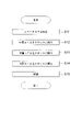
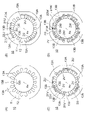
- FIG. It is a flowchart which shows the manufacturing process of the stator of Embodiment 1. It is a schematic diagram (A)-(D) for demonstrating the coil winding process of Embodiment 1.
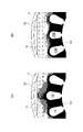
- FIG. It is a schematic diagram which shows the inserter used in the coil winding process of Embodiment 1 together with a stator core. It is a figure (A), (B) which shows the iron loss density distribution of the comparative example and the stator core of Embodiment 1.
- FIG. It is a graph which shows the relationship between the slot cross-sectional area ratio, the improvement rate of a motor efficiency, and the improvement rate of a coil usage amount.
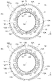
- FIG. 1 It is a plan view (A) which shows the stator of Embodiment 2 and a plan view (B) which shows a stator of a modification. It is a top view which shows the stator core of Embodiment 3.
- FIG. It is a plan view (A) which shows the stator core of Embodiment 4, and the schematic diagram (B) which shows the cross-sectional shape of each coil.
- FIG. 7 It is a plan view (A) which shows the stator of Embodiment 7, and a plan view (B) which shows a stator core. It is a top view which shows the other structural example of the stator core of each embodiment. It is a vertical sectional view which shows the compressor to which the electric motor of each embodiment is applicable. It is a figure which shows the refrigerating cycle apparatus provided with the compressor of FIG.
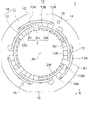
- FIG. 1 is a plan view showing the electric motor 100 of the first embodiment.
- the motor 100 is a three-phase synchronous motor, and is used, for example, in the compressor 500 (FIG. 20) described later. Further, the electric motor 100 is a permanent magnet embedded type electric motor in which a permanent magnet 55 is embedded in a rotor 5.
- the motor 100 has a stator 1 and a rotor 5 rotatably provided inside the stator 1. An air gap is provided between the stator 1 and the rotor 5.
- the stator 1 is incorporated inside a cylindrical shell 4.
- the rotor 5 is fixed to a shaft 6 which is a rotation shaft.
- the axis Ax which is the central axis of the shaft 6, defines the center of rotation of the rotor 5.
- the rotor 5 has a cylindrical rotor core 50 and a permanent magnet 55 attached to the rotor core 50.
- the rotor core 50 is formed by laminating a plurality of steel plates in the axial direction and fixing them by caulking or rivets.
- the steel plate is, for example, an electromagnetic steel plate having a thickness of 0.1 to 0.7 mm.
- a plurality of magnet insertion holes 51 are formed at equal intervals in the circumferential direction along the outer circumference of the rotor core 50.
- the number of magnet insertion holes 51 is 6 here.
- the magnet insertion hole 51 is formed from one end to the other end of the rotor core 50 in the axial direction.
- a permanent magnet 55 is arranged inside each magnet insertion hole 51.
- the permanent magnet 55 has a flat plate shape, has a rectangular cross section in a plane orthogonal to the axial direction, and has a thickness in the radial direction.
- One permanent magnet 55 is arranged in one magnet insertion hole 51. However, a plurality of permanent magnets 55 may be arranged in one magnet insertion hole 51.
- Each magnet insertion hole 51 corresponds to one magnetic pole of the rotor 5.
- the space between the adjacent magnet insertion holes 51 is an interpolar part.
- the magnet insertion hole 51 extends linearly in a direction orthogonal to a radial straight line (that is, a magnetic pole center line) passing through the center in the circumferential direction.
- the magnet insertion hole 51 may extend in a V shape.
- the number of magnet insertion holes 51 in the rotor core 50 corresponds to the number of poles in the rotor 5.
- the number of poles of the rotor 5 is 6.
- the number of poles of the rotor 5 is not limited to 6, and may be 2 or more.
- the permanent magnet 55 is composed of a rare earth sintered magnet containing neodymium (Nd), iron (Fe) and boron (B).
- the permanent magnet 55 is not limited to the rare earth magnet, and may be, for example, a ferrite magnet.
- the adjacent permanent magnets 55 have magnetic pole surfaces opposite to each other facing the outer peripheral side.
- Flux barriers 52 are formed on both sides of the magnet insertion hole 51 in the circumferential direction.
- the flux barrier 52 is a gap for suppressing leakage flux between adjacent magnetic poles.
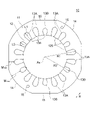
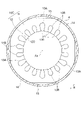
- FIG. 2 is a plan view showing the stator 1 of the first embodiment.
- the stator 1 has a stator core 10 and a coil 2 wound around the stator core 10 in a distributed winding manner.
- the stator core 10 is formed by laminating a plurality of steel plates in the axial direction and fixing them by caulking or the like.
- the steel plate is, for example, an electromagnetic steel plate having a thickness of 0.1 to 0.7 mm.
- the stator core 10 has an annular core back 11 and a plurality of teeth 12 extending radially inward from the core back 11.
- a tooth tip portion 120 facing the rotor 5 (FIG. 1) is formed inside the teeth 12 in the radial direction.
- an arcuate arc portion 14 centered on the axis Ax and a notch portion 15 which is a plane parallel to the axis Ax are formed on the outer periphery of the stator core 10.
- the arc portion 14 and the notch portion 15 are formed alternately in the circumferential direction.
- the arc portion 14 of the stator core 10 is fitted inside the shell 4 (FIG. 1).
- the shell 4 is a part of the closed container 502 of the compressor 500 (FIG. 20).
- the notch portion 15 is also referred to as a D-cut portion.
- a refrigerant flow path through which the refrigerant flows in the axial direction is formed between the notch portion 15 and the shell 4.
- the core back 11 may be provided with a through hole 16 that serves as a refrigerant flow path.
- the cross-sectional shape of the through hole 16 is circular or rectangular, and the number and arrangement of the through hole 16 are arbitrary.
- Slot 13 is formed between the teeth 12 adjacent to each other in the circumferential direction.
- the slot 13 is a portion in which the coil 2 is housed.
- An insulating portion (not shown) for insulating the stator core 10 and the coil 2 from each other is provided between the slot 13 and the coil 2.
- the number of slots 13 in the stator core 10 is referred to as the number of slots.
- the number of slots is three times the number of poles of the rotor 5, which is 18 here.
- the slot 13 of the stator core 10 includes a first slot 13A having a long radial length and a second slot 13B having a short radial length.
- the number of the first slots 13A is twice the number of poles of the rotor 5, and is 12 here.
- the number of the second slot 13B is the same as the number of poles of the rotor 5, which is 6 here.
- the first slot 13A is arranged on both sides of one second slot 13B, and these three slots form one set. Six sets of these three sets of slots, that is, the same number of sets as the number of poles of the rotor 5, are arranged.
- slot 13 When the first slot 13A and the second slot 13B are described without distinction, they are referred to as slot 13.
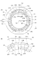
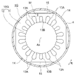
- FIG. 3 is a plan view showing the stator core 10.
- the first slot 13A has a slot opening 130 that communicates with the inner circumference of the stator core 10.
- the slot opening 130 is an entrance for inserting the coil 2U (2V) into the first slot 13A.
- the second slot 13B has a slot opening 130 that communicates with the inner circumference of the stator core 10.
- the slot opening 130 is an entrance for inserting the coil 2W into the second slot 13B.
- the first slot 13A has a length L1 in the radial direction.
- the second slot 13B has a length L2 in the radial direction.
- the length L1 of the first slot 13A is longer than the length L2 of the second slot 13B (L1> L2).
- the distance R1 from the axis Ax to the farthest end of the first slot 13A is longer than the distance R2 from the axis Ax to the farthest end of the second slot 13B (R1> R2).
- the distance M min from the first slot 13A to the notch portion 15 is the shortest, and the distance M max from the second slot 13B to the arc portion 14 is the longest. That is, the minimum width of the magnetic path of the core back 11 is M min , and the maximum width of the magnetic path of the core back 11 is M max .
- the coil 2 has a U-phase coil 2U, a V-phase coil 2V, and a W-phase coil 2W.
- the coils 2U, 2V, and 2W are wound around the stator core 10 by distributed winding, more specifically, concentric winding.
- the coils 2U, 2V, and 2W are all wound so that the coil pitch is 3 slots. Winding so that the coil pitch is 3 slots means that the coil is wound so as to straddle three teeth 12.
- the coils 2U, 2V, and 2W have different radial positions from each other.
- the U-phase coil 2U is located most radially outside, and the W-phase coil 2W is located most radially inside.
- the V-phase coil 2V is located between the coil 2U and the coil 2W in the radial direction.
- the arrangement of the coils 2U, 2V, and 2W is not limited to this example, and the positions of the coils 2U, 2V, and 2W in the radial direction may be different from each other.
- FIGS. 4 (A) and 4 (B) are schematic views showing winding patterns of coils 2U, 2V, and 2W.
- the coil 2U as the first coil is inserted into the first slot 13A.
- the portion inserted into the first slot 13A is referred to as an insertion portion 21U, and the portion extending along the end surface of the stator core 10 is referred to as a coil end 22U.
- the V-phase coil 2V as another first coil is inserted into a first slot 13A different from the first slot 13A into which the coil 2U is inserted.
- the portion inserted into the first slot 13A is referred to as an insertion portion 21V
- the portion extending along the end surface of the stator core 10 is referred to as a coil end 22V.
- the W-phase coil 2W as the second coil is inserted into the second slot 13B.
- the portion inserted into the second slot 13B is referred to as an insertion portion 21W
- the portion extending along the end surface of the stator core 10 is referred to as a coil end 22W.
- FIG. 4B is an enlarged view showing two first slots 13A and one second slot 13B.
- the insertion portion 21U of the coil 2U is inserted to the radial outside of the first slot 13A, that is, to the depth of the first slot 13A.
- the coil 2U is an outer layer coil located on the outermost radial direction among the coils 2U, 2V, and 2W.
- the insertion portion 21V of the coil 2V is inserted radially inward from the coil 2U in the first slot 13A different from the first slot 13A into which the insertion portion 21U of the coil 2U is inserted.
- the coil 2V is a middle layer coil located in the radial center of the coils 2U, 2V, and 2W.
- the insertion portion 21W of the coil 2W is inserted radially inside the coil 2V in the second slot 13B.
- the coil 2W is an inner layer coil located on the inner side in the radial direction among the coils 2U, 2V, and 2W.
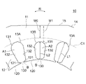
- FIG. 5 is an enlarged view showing the first slot 13A and the second slot 13B. Both the first slot 13A and the second slot 13B have a slot opening 130, a side edge 132, and a curved edge 131.
- the slot opening 130 is located between two adjacent tooth tips 120. More specifically, the slot opening 130 is located between the opposing end faces 121 of the two tooth tips 120.
- the side edge 132 is the edge on the teeth 12 side.
- the curved edge 131 is an edge on the outer peripheral side of the stator core 10.
- the straight line defining the radial outer boundary of the slot opening 130 is referred to as the opening boundary line B.
- the area of the region surrounded by the curved edge 131 of the first slot 13A, the opening boundary line B, and the pair of side edge 132s is defined as the cross-sectional area A1 of the first slot 13A.
- the area of the region surrounded by the curved edge 131 of the second slot 13B, the opening boundary line B, and the pair of side edge 132s is defined as the cross-sectional area A2 of the second slot 13B.
- the cross-sectional area A1 of the first slot 13A is, for example, 165.8 mm.
- the cross-sectional area A2 of the second slot 13B is, for example, 125.4 mm.
- the length L1 described with reference to FIG. 3 is the radial length of the first slot 13A including the radial length of the slot opening 130. Further, the length L2 is the radial length of the second slot 13B including the radial length of the slot opening 130.
- FIG. 6A is a schematic diagram showing a state in which the coil 2U and the coil 2V are inserted into the first slot 13A and the coil 2W is inserted into the second slot 13B.
- the coils 2U, 2V, 2W in the slot 13 are shown by hatching.
- FIG. 6B is a schematic diagram showing the cross-sectional shape of the coils 2U, 2V, and 2W.
- Each of the coils 2U, 2V, and 2W has a conductor 201 made of copper or aluminum, and an insulating coating 202 that covers the conductor 201. Since the thickness of the insulating coating 202 is very thin with respect to the diameter of the conductor 201, the diameter of the conductor 201 can be regarded as the diameter of the coil.
- the coil 2U has a diameter D1.
- the coil 2V has the same diameter as the diameter D1 of the coil 2U, that is, the diameter D1.
- the coil 2W has a diameter D2 smaller than the diameter D1 of the coil 2U. That is, the diameter D2 of the coil 2W inserted into the second slot 13B is smaller than the diameter D1 of the coils 2U and 2V inserted into the first slot 13A.
- the number of turns of the coil 2U accommodated in the first slot 13A, the number of turns of the coil 2V accommodated in the first slot 13A, and the number of turns of the coil 2W accommodated in the second slot 13B are equal to each other.
- the number of turns of each coil is, for example, 102 turns.
- FIG. 7 is a flowchart showing the manufacturing process of the stator 1.
- 8 (A) to 8 (D) are plan views for each step showing the winding step of the coil 2U, 2V, 2W among the manufacturing steps of the stator 1.
- stator core 10 is assembled by laminating a plurality of steel plates in the axial direction and fixing them by caulking or the like (step S11 in FIG. 7).
- step S12 the coil 2U is inserted into the first slot 13A of the stator core 10 (step S12). In other words, the coil 2U is wound around the teeth 12.
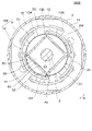
- FIG. 9 is a perspective view showing the inserter 9 used in the winding process of the coil 2U together with the stator core 10.
- the inserter 9 has an annular base 90 and a plurality of blades (claws) 91 extending axially from the base 90.
- the number of blades 91 is the same as the number of slots 13 of the stator core 10.
- a slit 92 is formed between the blades 91 adjacent to each other in the circumferential direction.
- the coil 2U is attached to the slit 92 of the inserter 9 separately in three winding parts. Each winding portion of the coil 2U is attached to the slit 92 so as to straddle the three blades 91.
- the inserter 9 is inserted on the inner peripheral side of the stator core 10 so that the blade 91 faces the teeth 12. As shown in FIG. 8B, the coil 2U held in the slit 92 is inserted into the first slot 13A from the inner peripheral side.
- the coil 2U remains in the stator core 10 with the coil 2U inserted in the first slot 13A. That is, the insertion of the coil 2U into the first slot 13A, in other words, the winding of the coil 2U around the stator core 10 is completed.
- the coil 2V is inserted into the first slot 13A (step S13).
- the inserter 9 is used in the same manner as the coil 2U, and as shown in FIG. 8C, the coil 2V is placed in the first slot 13A different from the first slot 13A into which the coil 2U is inserted. Insert from the peripheral side.
- the coil 2V is arranged radially inside the coil 2U.
- the coil end 22U of the coil 2U and the coil end 22V of the coil 2V are arranged without interfering with each other.
- the coil 2W is inserted into the second slot 13B (step S14).
- the coil 2W is located radially inside the coil 2V.
- the inserter 9 is used in the same manner as the coils 2U and 2V, and the coil 2W is inserted into the second slot 13B from the inner peripheral side as shown in FIG. 8D.
- the coil 2W is arranged radially inside the coil 2V.
- the coil end 22V of the coil 2V and the coil end 22W of the coil 2W are arranged without interfering with each other.
- an insulating film or the like is arranged between the coil ends 22U and 22V and between the coil ends 22V and 22W so that the coil ends 22U, 22V and 22W do not come into contact with each other.
- the connection of the coils 2U, 2V, and 2W may be a Y connection or a delta connection. According to the specifications of the motor 100, Y connection is selected when high voltage / low current is required, and delta connection is selected when low voltage / high current is required. As a result, the production of the stator 1 is completed.
- the coils 2U, 2V, 2W can be arranged in order from the outside in the radial direction.
- the coil 2W is inserted into a slot having the same length as the slot into which the coil 2U is inserted, the coil 2W is not inserted all the way into the slot, so that a dead space is created in the slot.
- the radial length L2 of the second slot 13B into which the coil 2W is inserted is shorter than the radial length L1 of the first slot 13A.
- the minimum width of the magnetic path of the core back 11 is determined by the minimum distance from each slot 13 to the outer circumference of the stator core 10 (notch portion 15 in FIG. 5). Assuming that the second slot 13B has the same length as the first slot 13A, the minimum distance from the second slot 13B to the notch 15 is such that M0 passes through the outermost point of the first slot 13A. It is the minimum distance from the circle C1 to the notch portion 15.
- the minimum distance from the second slot 13B to the notch portion 15 becomes longer from M0 to M1 described above.
- the width of the magnetic path in the core back 11 is widened, and the magnetic flux density is reduced.
- magnetic saturation is less likely to occur and iron loss is reduced.
- FIG. 10A and 10 (B) are diagrams showing the iron loss density distribution of the stator core 10 obtained by magnetic field analysis.
- FIG. 10A shows the iron loss density distribution in the stator core 10 of the comparative example in which all the slots 13 have the same length
- FIG. 10B shows the iron loss density distribution in the stator core 10 of the first embodiment. show.
- the radial width of the core back 11 is locally located at the portion where the distance between the slot 13 and the notch 15 is the shortest. It becomes narrower, and the iron loss density becomes higher in that part due to magnetic saturation.
- the magnetic flux is less likely to leak from the arc portion 14 of the stator core 10 to the shell 4 (magnetic material). That is, the iron loss caused by the leakage flux to the shell 4 is suppressed, and the motor efficiency can be further improved.
- the rigidity of the stator core 10 is improved by reducing the number of narrow portions in the core back 11.
- the rigidity of the stator core 10 it is possible to reduce the vibration caused by the electromagnetic excitation force generated when the motor 100 rotates. As a result, noise due to contact between the stator core 10 and the shell 4 can be reduced, and the quietness of the motor 100 can be improved.
- the diameter D2 of the coil 2W inserted into the second slot 13B is smaller than the diameter D1 of the coils 2U and 2V inserted into the first slot 13A (D1> D2). Since the coil 2W inserted into the second slot 13B having a short radial length is thin, the coil 2W can be easily inserted into the second slot 13B.
- the space factor of the coil 2U (coil 2V) in the first slot 13A and the space factor of the coil 2W in the second slot 13B can be brought close to the same.
- the space factor SF1 of the coil 2U in the first slot 13A is a value obtained by dividing the total cross-sectional area of the coil 2U in the first slot 13A (that is, the coil cross-sectional area S1) by the cross-sectional area A1 of the first slot 13A.
- the coil cross-sectional area S1 in the first slot 13A is a value obtained by multiplying ⁇ ⁇ D1 2/4 , which is the cross-sectional area of the coil 2U, by the number of turns of the coil 2U.
- the space factor SF2 of the coil 2W in the second slot 13B is a value obtained by dividing the total cross-sectional area of the coil 2W in the second slot 13B (that is, the coil cross-sectional area S2) by the cross-sectional area A2 of the second slot 13B.
- the coil cross-sectional area S2 in the second slot 13B is a value obtained by multiplying ⁇ ⁇ D2 2/4 , which is the cross-sectional area of the coil 2W, by the number of turns of the coil 2W.
- the coil cross-sectional area S1 is 80.1 mm.
- the coil cross-sectional area S2 is 60.6 mm.
- the coil 2U and 2V accommodated in the first slot 13A and the coil 2W accommodated in the second slot 13B have the same copper loss. Can be improved and inserted as easily.
- the relationship between the space factor SF1 and SF2 of the first slot 13A and the second slot 13B is not limited to the relationship described here.
- the space factor SF1 of the first slot 13A may be lower than the space factor SF2 of the second slot 13B (SF1 ⁇ SF2).
- the space factor SF1 is 48.3% as described above.
- the coil cross-sectional area S2 is 64.9 mm.
- the copper loss of the coil 2W in the second slot 13B can be reduced, whereby the motor efficiency can be reduced. Can be improved.
- the space factor SF1 of the first slot 13A may be higher than the space factor SF2 of the second slot 13B (SF1> SF2).
- the space factor SF1 is 48.3% as described above.
- the coil cross-sectional area S2 is 57.9 mm.
- the ratio A2 / A1 of the cross-sectional area A2 of the second slot 13B to the cross-sectional area A1 of the first slot 13A described above is referred to as a slot cross-sectional area ratio.
- FIG. 11 is a diagram showing the relationship between the slot cross-sectional area ratio A2 / A1 and the improvement rate of the motor efficiency and the improvement rate of the coil usage amount.
- the horizontal axis indicates the slot cross-sectional area ratio A2 / A1.
- the vertical axis on the left side shows the improvement rate of motor efficiency, and the vertical axis on the right side shows the improvement rate of coil usage.
- the curve shown by the solid line shows the motor efficiency
- the straight line shown by the broken line shows the coil usage amount.
- the improvement rate of the motor efficiency is the rate of change of the motor efficiency based on the motor efficiency of the comparative example (FIG. 10 (A)) in which the slot cross-sectional area ratio A2 / A1 is 1.
- the improvement rate of the motor efficiency is positive, the motor efficiency is higher than the standard value, and when the improvement rate is negative, the motor efficiency is lower than the standard value.
- the improvement rate of the coil usage amount is the improvement rate of the coil usage amount based on the usage amount of the coil 2 in the comparative example (FIG. 10A) in which the slot cross-sectional area ratio A2 / A1 is 1. ..
- the improvement rate of the coil usage is positive, the usage of the coil 2 is larger than the reference value, and when the improvement rate is negative, the usage of the coil 2 is smaller than the reference value.
- the space factors SF1 and SF2 are the same, when the slot cross-sectional area ratio A2 / A1 decreases, the coil cross-sectional area S2 becomes smaller than the coil cross-sectional area S1. That is, as the slot cross-sectional area ratio A2 / A1 decreases, the coil usage of the coil 2W decreases linearly.
- the amount of coil used can be effectively reduced while suppressing the decrease in motor efficiency to 0.01% or less.
- the decrease in motor efficiency is within the permissible range if it is 0.01% or less. If 0.64 ⁇ A2 / A1 ⁇ 1, the amount of coil used can be reduced while keeping the decrease in motor efficiency within the allowable range.
- the coil usage amount can be reduced without lowering the motor efficiency as compared with the comparative example.
- the amount of coil used is smaller than in the range of 0.89 ⁇ A2 / A1 ⁇ 1. Therefore, in the range of 0.64 ⁇ A2 / A1 ⁇ 0.89, the amount of coil used can be reduced particularly effectively while keeping the decrease in motor efficiency within the allowable range.
- the motor efficiency is the highest in the range of 0.86 ⁇ A2 / A1 ⁇ 0.92. That is, the motor efficiency can be improved particularly effectively, and the amount of coil used can be reduced.
- the coils 2U and 2V are inserted into the first slot 13A, and the coils 2W are inserted into the second slot 13B.
- the coils inserted in the first slot 13A and the second slot 13B are not limited to the above example.
- the coil (outer layer coil) arranged on the outermost side in the radial direction is inserted into the first slot 13A
- the coil (middle layer coil) arranged on the outermost side in the second radial direction is inserted into another first slot 13A.
- the coil (inner layer coil) arranged on the innermost side in the radial direction may be inserted into the second slot 13B.
- the stator 1 of the first embodiment has a stator core 10 having a first slot 13A and a second slot 13B, and coils 2U, 2V, 2W wound around the stator core 10 in a distributed winding manner.
- the coils 2U and 2V (first coil) are inserted into the first slot 13A
- the coils 2W (second coil) are inserted into the second slot 13B.
- the radial length L1 of the first slot 13A is longer than the radial length L2 of the second slot 13B
- the diameter D1 of the coils 2U and 2V is larger than the diameter D2 of the coil 2W.
- the length L2 of the second slot 13B is shorter than the length L1 of the first slot 13A, a wide magnetic path can be formed between the second slot 13B and the outer periphery of the stator core 10. As a result, magnetic saturation in the core back 11 can be suppressed and motor efficiency can be improved.
- the diameter D2 of the coil 2W in the second slot 13B is small, the coil 2W can be easily inserted into the second slot 13B, and the winding work of the coils 2U, 2V, 2W can be simplified.
- the diameter D2 of the coil 2W is small, the amount of coil used can be reduced and the manufacturing cost of the motor 100 can be reduced.
- the space factor of the coils 2U, 2V and the coil 2W Copper loss can be similarly reduced and motor efficiency can be improved.
- the insertion of the coils 2U, 2V and the coil 2W can be similarly facilitated.
- the space factor SF1 of the coils 2U and 2V in the first slot 13A lower than the space factor SF2 of the coil 2W in the second slot 13B (SF1 ⁇ SF2), the copper loss of the coil 2W is reduced. , Motor efficiency can be improved.
- the space factor SF1 of the coils 2U and 2V in the first slot 13A higher than the space factor SF2 of the coil 2W in the second slot 13B (SF1> SF2), a second having a short radial length.
- the coil 2W can be easily inserted in the slot 13B.
- the coil usage amount can be reduced without lowering the motor efficiency.
- the amount of coil used can be reduced particularly effectively while keeping the decrease in motor efficiency within the allowable range.
- the motor efficiency can be improved particularly effectively and the coil usage amount can be reduced.
- notch portion 15 is formed on the outer periphery of the stator core 10, a refrigerant flow path is formed between the notch portion 15 and the shell 4. This makes it possible to improve the operating efficiency of the compressor provided with the motor 100.
- the notches 15 are formed at four points in the circumferential direction on the outer periphery of the stator core 10, more steel plate portions having the shape shown in FIG. 3 can be punched out from one electromagnetic steel plate. Therefore, the manufacturing cost of the electric motor 100 can be reduced.
- the second slot 13B is the same as the number of poles of the rotor 5, as shown in FIG. 1, the second slot 13B is in a constant relative position with respect to any magnetic pole of the rotor 5. As a result, magnetic imbalance can be suppressed.
- the number of slots is three times the number of poles.
- the winding coefficient becomes 1 and becomes the maximum.
- the winding coefficient is 0.966 for all knot windings and 0.933 for short knot windings. The larger the winding coefficient, the more effectively the magnetic force of the permanent magnet 55 can be used, so that the output of the motor 100 can be increased. Further, since the current required to obtain the same output is small, copper loss can be reduced.
- the permanent magnet 55 of the rotor 5 is a rare earth magnet or a ferrite magnet, a high magnetic force can be generated and the motor output can be increased.
- FIG. 12A is a plan view showing the stator 1A of the second embodiment.
- the shape of the outer circumference of the stator core 10A of the stator 1A of the second embodiment is different from that of the stator 1 of the first embodiment.
- the outer circumference of the stator core 10A has six arc portions 14 and six notched portions 15.
- the arc portion 14 and the notch portion 15 are alternately arranged in the circumferential direction.
- the stator 1A is formed with the first slot 13A and the second slot 13B described in the first embodiment.
- the coil 2U as the first coil is inserted into the first slot 13A
- the coil 2V as the other first coil is inserted into another first slot 13A
- the coil 2W as the second coil is the second coil. It is inserted in slot 13B.
- the notches 15 can be made to face the second slot 13B in the radial direction.
- the arc portion 14 faces the two first slots 13A in the radial direction.
- the first slot 13A faces the notch 15
- the first slot 13A faces the arc 14
- the second slot 13B faces the notch 14.
- the stator core 10A of the second embodiment since the first slot 13A and the arc portion 14 face each other and the second slot 13B and the notch portion 15 face each other, the distance from the slot 13 to the outer periphery of the stator core 10A is reached. The distance approaches a certain level. Therefore, even if the second slot 13B having a short radial length is provided, the flow of the magnetic flux in the stator core 10A can be uniformly approached. As a result, the electromagnetic vibration force generated when the motor 100 rotates can be reduced.
- FIG. 12B is a plan view showing the stator 1B of the modified example of the second embodiment.
- the outer circumference of the stator core 10B of the stator 1B has six arc portions 14 and six notches 15.
- the notch 15 faces the two first slots 13A in the radial direction.
- the arc portion 14 faces the second slot 13B in the radial direction.
- the first slot 13A and the notch portion 15 face each other, and the second slot 13B and the arc portion 14 face each other. Therefore, even if the second slot 13B having a short radial length is provided, the flow of the magnetic flux in the stator core 10B can be uniformly approached. As a result, the electromagnetic vibration force generated when the motor 100 rotates can be reduced.
- stator core 10A (10B) since the stator core 10A (10B) has six notches 15 which are the same as the number of poles of the rotor 5, the flow of the magnetic flux in the stator core 10A (10B) is uniformly brought close to each other. It is possible to reduce the electromagnetic vibration force generated when the motor 100 rotates.
- FIG. 13 is a plan view showing the stator core 10C of the stator of the third embodiment.
- the stator core 10C of the third embodiment has a first slot 13A having the same number of poles as the rotor 5 (FIG. 1) and a second slot 13B having twice the number of poles. That is, the number of the first slots 13A is 6, and the number of the second slots 13B is 12.
- the coil 2U When winding the coil 2U, 2V, 2W, the coil 2U is inserted into the first slot 13A, the coil 2V is inserted into the second slot 13B, and the coil 2W is inserted into another second slot 13B.
- the coils inserted into the first slot 13A and the second slot 13B are not limited to the above example.
- the outer layer coil may be inserted into the first slot 13A
- the middle layer coil may be inserted into the second slot 13B
- the inner layer coil may be inserted into another second slot 13B.
- the outer circumference of the stator core 10C has four arc portions 14 and four notch portions 15. However, as described in the second embodiment, it may have six arc portions 14 and six notched portions 15.
- the stator of the third embodiment is the same as the stator 1 described in the first embodiment except for the above points.
- stator core 10C since the stator core 10C has the same number of first slots 13A as the number of poles of the rotor 5 and the second slot 13B which is twice the number of poles, it is more than the first embodiment.
- the width of the magnetic path in the core back 11 can be widened, and the motor efficiency can be further improved.
- FIG. 14A is a plan view showing the stator core 10D of the stator of the fourth embodiment.
- the stator core 10D of the fourth embodiment has a first slot 13A, a second slot 13B, and a third slot 13C.
- the number of the first slot 13A, the second slot 13B, and the third slot 13C are all the same as the number of poles of the rotor 5, that is, six.
- the first slot 13A has a length L1 in the radial direction
- the second slot 13B has a length L2 in the radial direction
- the third slot 13C has a length L3 in the radial direction.
- the lengths L1, L2 and L3 satisfy L1> L2> L3.
- the length R1 from the axis Ax to the farthest end of the first slot 13A the length R2 from the axis Ax to the farthest end of the second slot 13B, and the farthest end from the axis Ax to the third slot 13C.
- the length up to R3 satisfies R1> R2> R3.
- virtual circles C1, C2, and C3 centered on the axis Ax and having diameters R1, R2, and R3 are shown by broken lines.
- the coil 2U (FIG. 1) as the first coil is inserted into the first slot 13A.
- the coil 2V (FIG. 1) as the second coil is inserted into the second slot 13B.
- the coil 2W (FIG. 1) as the third coil is inserted into the third slot 13C.
- the coil 2U When winding the coils 2U, 2V, 2W, the coil 2U is inserted into the first slot 13A, then the coil 2V is inserted into the second slot 13B, and then the coil 2W is inserted into the third slot 13C.
- FIG. 14B is a schematic diagram showing the cross-sectional shape of the coils 2U, 2V, and 2W.
- each of the coils 2U, 2V, and 2W has a conductor 201 and an insulating coating 202. Since the thickness of the insulating coating 202 is very thin with respect to the diameter of the conductor 201, the diameter of the conductor 201 can be regarded as the diameter of the coil.
- the coil 2U has a diameter D1.
- the coil 2V has a diameter D2.
- the coil 2W has a diameter D3. It is desirable that the diameters D1, D2 and D3 satisfy D1> D2> D3.
- the shorter the slot length the more difficult it is to insert the coil. Therefore, the diameter D3 of the coil 2W inserted into the slot 13C having the smallest radial length is made the smallest, and the coil is inserted into the second smallest slot 13B.
- the diameter D2 of the coil 2V the second smallest, it is possible to facilitate the insertion of the coils 2V and 2W into the slots 13B and 13C.
- the outer circumference of the stator core 10D has four notches 15 and four arcs 14. However, as described in the second embodiment, it may have six arc portions 14 and six notched portions 15.
- the stator of the fourth embodiment is the same as the stator 1 described in the first embodiment except for the above points.
- the stator core 10D has the first slot 13A, the second slot 13B, and the third slot 13C, and the radial lengths L1, L2, L3 of the slots 13A, 13B, 13C. Satisfies L1> L2> L3. Therefore, a wide magnetic path can be formed between the second slot 13B and the third slot 13C and the outer periphery of the stator core 10, magnetic saturation can be suppressed, and motor efficiency can be improved.
- the diameters D1, D2, D3 of the coils 2U, 2V, 2W satisfy D1> D2> D3, so that the coils 2V, 2W to the second slot 13B and the third slot 13C having a short radial length can be used. The insertion work can be facilitated.
- FIG. 15 is a diagram showing the motor 100E of the fifth embodiment.
- the motor 100E of the fifth embodiment has a stator 1E and a rotor 5E.
- the number of poles of the rotor 5E of the motor 100E is 4, and the number of slots of the stator 1E is 12.
- each magnet insertion hole 51 In the rotor core 50 of the rotor 5E, four magnet insertion holes 51 are formed at equal intervals in the circumferential direction. One permanent magnet 55 is arranged in each magnet insertion hole 51, and each magnet insertion hole 51 corresponds to one magnetic pole. That is, the number of poles of the rotor 5E is 4.
- the rotor 5E is otherwise configured in the same manner as the rotor 5 of the first embodiment.
- FIG. 16A is a diagram showing the stator 1E of the motor 100E
- FIG. 16B is a plan view showing the stator core 10E. As shown in FIG. 16B, the stator core 10E has 12 slots 13.
- the slot 13 has a first slot 13A having a long radial length and a second slot 13B having a short radial length.
- the number of the first slots 13A is twice the number of poles of the rotor 5, that is, eight.
- the number of the second slot 13B is the same as the number of poles of the rotor 5, that is, four.
- the coil 2U as the first coil is inserted into the first slot 13A.
- the coil 2V as another first coil is inserted into another first slot 13A.
- the coil 2W as the second coil is inserted into the second slot 13B.
- the coil 2U When winding the coil 2U, 2V, 2W, the coil 2U is inserted into the first slot 13A, then the coil 2V is inserted into another first slot 13A, and then the coil 2W is inserted into the second slot 13B.
- the coils inserted into the slots 13A, 13B, 13C are not limited to the above example.
- the outer layer coil may be inserted into the first slot 13A
- the middle layer coil may be inserted into another first slot 13A
- the inner layer coil may be inserted into the second slot 13B.
- the number of the first slot 13A may be the same as the number of poles of the rotor 5, and the number of the second slots 13B may be twice the number of poles of the rotor 5. .. Further, as described in the fourth embodiment (FIG. 14), slots 13A, 13B, 13C having different radial lengths may be formed in the stator core 10F.
- the outer circumference of the stator core 10E has four arc portions 14 and four notch portions 15. However, as described in the second embodiment, it may have six arc portions 14 and six notched portions 15.
- the electric motor 100E of the fifth embodiment is the same as the electric motor 100 described in the first embodiment except for the above points.
- the effect described in the first embodiment can be obtained in the motor 100E having four poles and 12 slots. Further, since the number of poles is smaller than that of the motor 100 having 6 poles and 18 slots according to the first embodiment, the drive frequency for driving the motor 100 is reduced. Therefore, iron loss in the motor 100E can be suppressed.
- FIG. 16 is a diagram showing the motor 100F of the sixth embodiment.
- the motor 100F of the sixth embodiment has a stator 1F and a rotor 5F.
- the number of poles of the rotor 5F of the motor 100F is 8, and the number of slots of the stator 1F is 24.
- Eight magnet insertion holes 51 are formed at equal intervals in the circumferential direction in the rotor core 50 of the rotor 5F.
- One permanent magnet 55 is arranged in each magnet insertion hole 51, and each magnet insertion hole 51 corresponds to one magnetic pole. That is, the number of poles of the rotor 5F is 8.
- the rotor 5F is otherwise configured in the same manner as the rotor 5 of the first embodiment.
- the slot 13 has a first slot 13A having a long radial length and a second slot 13B having a short radial length.
- the number of the first slots 13A is twice the number of poles of the rotor 5, that is, 16.
- the number of the second slot 13B is the same as the number of poles of the rotor 5, that is, eight.
- the coil 2U as the first coil is inserted into the first slot 13A.
- the coil 2V as another first coil is inserted into another first slot 13A.
- the coil 2W as the second coil is inserted into the second slot 13B.
- the coil 2U When winding the coil 2U, 2V, 2W, the coil 2U is inserted into the first slot 13A, then the coil 2V is inserted into another first slot 13A, and then the coil 2W is inserted into the second slot 13B.
- the coils inserted into the slots 13A, 13B, 13C are not limited to the above example.
- the outer layer coil may be inserted into the first slot 13A
- the middle layer coil may be inserted into another first slot 13A
- the inner layer coil may be inserted into the second slot 13B.
- the number of the first slot 13A may be the same as the number of poles of the rotor 5, and the number of the second slots 13B may be twice the number of poles of the rotor 5. .. Further, as described in the fourth embodiment (FIG. 14), slots 13A, 13B, 13C having different radial lengths may be formed in the stator core 10F.
- the outer circumference of the stator core 10E has four arc portions 14 and four notch portions 15. However, as described in the second embodiment, it may have six arc portions 14 and six notched portions 15.
- the electric motor 100F of the sixth embodiment is the same as the electric motor 100 described in the first embodiment except for the above points.
- the effect described in the first embodiment can be obtained in the motor 100F having 8 poles and 24 slots.
- FIG. 19 shows a stator core 10G of another configuration example.
- the notch portion 15 is formed radially inside the notch portion 15 of the first embodiment.
- the operating efficiency of the compressor can be improved, and the operating efficiency of the refrigerating cycle device equipped with the compressor can be improved.
- the distance M from each slot 13 to the notch portion 15 is shortened, but at least in the portion formed by the second slot 13B, the magnetic path width in the core back 11 is secured and the occurrence of magnetic saturation is suppressed. be able to.
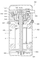
- FIG. 20 is a vertical sectional view showing the compressor 500.
- the compressor 500 is, but is not limited to, a scroll compressor here.
- the compressor 500 includes a compression mechanism 510, an electric motor 100 for driving the compression mechanism 510, a main shaft 501 for connecting the compression mechanism 510 and the electric motor 100, and a subframe 503 for supporting a lower end portion (sub-shaft portion) of the main shaft 501. And a closed container 502 in which these are housed.
- the spindle 501 is the shaft 6 shown in FIG.
- Refrigerating machine oil 504 is stored in the oil sump 505 at the bottom of the closed container 502.
- the compression mechanism 510 includes a fixed scroll 511 and a swing scroll 512, an old dam ring 513, a compliant frame 514, and a guide frame 515. Both the fixed scroll 511 and the swing scroll 512 have plate-shaped spiral teeth and are combined to form a compression chamber 516.
- a suction pipe 506 penetrating the closed container 502 is press-fitted into the fixed scroll 511. Further, a discharge pipe 507 is provided which penetrates the closed container 502 and discharges the high-pressure refrigerant gas discharged from the discharge port of the fixed scroll 511 to the outside (refrigeration cycle).
- the closed container 502 has a cylindrical shell 4 into which the motor 100 is incorporated by shrink fitting. Further, a glass terminal 508 for electrically connecting the stator 1 of the motor 100 and the drive circuit is fixed to the closed container 502 by welding.
- the high-pressure refrigerant gas compressed in the compression chamber 516 is discharged into the closed container 502 from the discharge port 511a of the fixed scroll 511, and is discharged to the outside from the discharge pipe 507. Further, a part of the refrigerant gas discharged from the compression chamber 516 into the closed container 502 passes through the refrigerant flow path between the notch portion 15 (FIG. 1) of the stator 1 and the shell 4, and cools the motor 100. do.
- the scroll compressor has been described as an example of the compressor, but the electric motor of each embodiment may be applied to a compressor other than the scroll compressor.
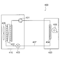
- FIG. 21 is a diagram showing a refrigeration cycle device 400.
- the refrigeration cycle device 400 is, but is not limited to, an air conditioner here.
- the refrigeration cycle device 400 includes a compressor 401, a condenser 402, a throttle device (decompression device) 403, and an evaporator 404.
- the compressor 401, the condenser 402, the throttle device 403 and the evaporator 404 are connected by a refrigerant pipe 407 to form a refrigeration cycle. That is, the refrigerant circulates in the order of the compressor 401, the condenser 402, the throttle device 403, and the evaporator 404.
- the compressor 401, the condenser 402, and the throttle device 403 are provided in the outdoor unit 410.
- the compressor 401 is composed of the compressor 500 shown in FIG. 20.
- the outdoor unit 410 is provided with an outdoor blower 405 that blows air to the condenser 402.
- the evaporator 404 is provided in the indoor unit 420.
- the indoor unit 420 is provided with an indoor blower 406 that blows air to the evaporator 404.
- the operation of the refrigeration cycle device 400 is as follows.
- the compressor 401 compresses and sends out the sucked refrigerant.
- the condenser 402 exchanges heat between the refrigerant flowing in from the compressor 401 and the outdoor air, condenses the refrigerant, liquefies it, and sends it to the refrigerant pipe 407.
- the outdoor blower 405 supplies outdoor air to the condenser 402.
- the throttle device 403 adjusts the pressure of the refrigerant flowing through the refrigerant pipe 407.
- the evaporator 404 exchanges heat between the refrigerant reduced to a low pressure by the throttle device 403 and the air in the room.
- the refrigerant takes heat from the air, evaporates (vaporizes), and is sent out to the refrigerant pipe 407.
- the indoor blower 406 supplies the air whose heat has been taken away by the refrigerant by the evaporator 404 into the room.
- the motor of each embodiment has high motor efficiency, the operating efficiency of the compressor 401 can be improved, and thereby the operating efficiency of the refrigerating cycle device 400 can be improved.
Landscapes
- Engineering & Computer Science (AREA)
- Power Engineering (AREA)
- Windings For Motors And Generators (AREA)
- Iron Core Of Rotating Electric Machines (AREA)
Priority Applications (2)
| Application Number | Priority Date | Filing Date | Title |
|---|---|---|---|
| PCT/JP2020/036167 WO2022064624A1 (ja) | 2020-09-25 | 2020-09-25 | ステータ、電動機、圧縮機、冷凍サイクル装置およびステータの製造方法 |
| JP2022551508A JPWO2022064624A1 (cg-RX-API-DMAC7.html) | 2020-09-25 | 2020-09-25 |
Applications Claiming Priority (1)
| Application Number | Priority Date | Filing Date | Title |
|---|---|---|---|
| PCT/JP2020/036167 WO2022064624A1 (ja) | 2020-09-25 | 2020-09-25 | ステータ、電動機、圧縮機、冷凍サイクル装置およびステータの製造方法 |
Publications (1)
| Publication Number | Publication Date |
|---|---|
| WO2022064624A1 true WO2022064624A1 (ja) | 2022-03-31 |
Family
ID=80846296
Family Applications (1)
| Application Number | Title | Priority Date | Filing Date |
|---|---|---|---|
| PCT/JP2020/036167 Ceased WO2022064624A1 (ja) | 2020-09-25 | 2020-09-25 | ステータ、電動機、圧縮機、冷凍サイクル装置およびステータの製造方法 |
Country Status (2)
| Country | Link |
|---|---|
| JP (1) | JPWO2022064624A1 (cg-RX-API-DMAC7.html) |
| WO (1) | WO2022064624A1 (cg-RX-API-DMAC7.html) |
Cited By (1)
| Publication number | Priority date | Publication date | Assignee | Title |
|---|---|---|---|---|
| CN115864770A (zh) * | 2022-12-22 | 2023-03-28 | 美的威灵电机技术(上海)有限公司 | 转子冲片、电机、压缩机和电器 |
Citations (8)
| Publication number | Priority date | Publication date | Assignee | Title |
|---|---|---|---|---|
| JPS5598182U (cg-RX-API-DMAC7.html) * | 1978-12-27 | 1980-07-08 | ||
| JPS61443U (ja) * | 1984-06-06 | 1986-01-06 | 株式会社東芝 | 三相誘導電動機 |
| JPH0613357U (ja) * | 1992-07-10 | 1994-02-18 | ダイキン工業株式会社 | 電動機 |
| JP2001045683A (ja) * | 1999-07-29 | 2001-02-16 | Fujitsu General Ltd | 電動機 |
| JP2001061248A (ja) * | 1999-08-20 | 2001-03-06 | Fujitsu General Ltd | 電動機 |
| WO2006098065A1 (ja) * | 2005-02-22 | 2006-09-21 | Mitsubishi Denki Kabushiki Kaisha | 単相電動機及び密閉形圧縮機 |
| JP2008005563A (ja) * | 2004-09-22 | 2008-01-10 | Amada Co Ltd | 同期電動機およびそれを用いた同期電動機システム |
| JP2017200403A (ja) * | 2016-04-28 | 2017-11-02 | アイシン精機株式会社 | 三相同期機およびその製造方法 |
Family Cites Families (2)
| Publication number | Priority date | Publication date | Assignee | Title |
|---|---|---|---|---|
| JP3489692B2 (ja) * | 1994-10-20 | 2004-01-26 | 株式会社デンソー | 回転電機の電機子及びその巻装方法 |
| JPH11125183A (ja) * | 1997-10-23 | 1999-05-11 | Matsushita Refrig Co Ltd | 密閉型電動圧縮機 |
-
2020
- 2020-09-25 WO PCT/JP2020/036167 patent/WO2022064624A1/ja not_active Ceased
- 2020-09-25 JP JP2022551508A patent/JPWO2022064624A1/ja active Pending
Patent Citations (8)
| Publication number | Priority date | Publication date | Assignee | Title |
|---|---|---|---|---|
| JPS5598182U (cg-RX-API-DMAC7.html) * | 1978-12-27 | 1980-07-08 | ||
| JPS61443U (ja) * | 1984-06-06 | 1986-01-06 | 株式会社東芝 | 三相誘導電動機 |
| JPH0613357U (ja) * | 1992-07-10 | 1994-02-18 | ダイキン工業株式会社 | 電動機 |
| JP2001045683A (ja) * | 1999-07-29 | 2001-02-16 | Fujitsu General Ltd | 電動機 |
| JP2001061248A (ja) * | 1999-08-20 | 2001-03-06 | Fujitsu General Ltd | 電動機 |
| JP2008005563A (ja) * | 2004-09-22 | 2008-01-10 | Amada Co Ltd | 同期電動機およびそれを用いた同期電動機システム |
| WO2006098065A1 (ja) * | 2005-02-22 | 2006-09-21 | Mitsubishi Denki Kabushiki Kaisha | 単相電動機及び密閉形圧縮機 |
| JP2017200403A (ja) * | 2016-04-28 | 2017-11-02 | アイシン精機株式会社 | 三相同期機およびその製造方法 |
Cited By (1)
| Publication number | Priority date | Publication date | Assignee | Title |
|---|---|---|---|---|
| CN115864770A (zh) * | 2022-12-22 | 2023-03-28 | 美的威灵电机技术(上海)有限公司 | 转子冲片、电机、压缩机和电器 |
Also Published As
| Publication number | Publication date |
|---|---|
| JPWO2022064624A1 (cg-RX-API-DMAC7.html) | 2022-03-31 |
Similar Documents
| Publication | Publication Date | Title |
|---|---|---|
| KR100877465B1 (ko) | 단상 전동기 및 밀폐형 압축기 | |
| US10075034B2 (en) | Magnet-embedded motor and compressor having magnet-embedded motor | |
| CN108886276B (zh) | 电动机、送风机、压缩机及空气调节装置 | |
| EP3633827B1 (en) | Electric motor, compressor, and air conditioning device | |
| CN105594099B (zh) | 永磁铁埋入型电动机、压缩机以及制冷空调装置 | |
| KR102237601B1 (ko) | 자석 매립형 모터 및 자석 매립형 모터를 가지는 압축기 | |
| CN213602456U (zh) | 定子冲片、定子铁芯、永磁同步电机、压缩机和制冷设备 | |
| JPWO2018203364A1 (ja) | ロータ、電動機、圧縮機および空気調和装置 | |
| JP6942246B2 (ja) | ロータ、電動機、圧縮機および空気調和装置 | |
| US11888353B2 (en) | Motor, compressor, and air conditioner | |
| CN110622394B (zh) | 定子、电动机、压缩机及空调装置 | |
| WO2014125599A1 (ja) | 永久磁石埋込型電動機、圧縮機及び冷凍空調装置 | |
| CN112564318B (zh) | 定子冲片、定子铁芯、电机、压缩机和制冷设备 | |
| JP7237178B2 (ja) | ロータ、電動機、圧縮機、及び空気調和機 | |
| JPWO2018220806A1 (ja) | リラクタンスモータ、圧縮機および空気調和装置 | |
| WO2023032134A1 (ja) | 電動機、圧縮機および冷凍サイクル装置 | |
| US11962191B2 (en) | Rotor, electric motor, compressor, and air conditioner | |
| JP7778279B1 (ja) | ロータ、モータ、圧縮機および冷凍サイクル装置 | |
| JP7486911B2 (ja) | 電動機、圧縮機、冷凍サイクル装置、着磁方法および着磁装置 | |
| JP7479562B2 (ja) | 電動機、圧縮機および冷凍サイクル装置 | |
| WO2023037438A1 (ja) | ロータ、モータ、圧縮機および冷凍サイクル装置 | |
| WO2023248466A1 (ja) | ステータ、電動機、圧縮機、冷凍サイクル装置および電動機の製造方法 | |
| WO2023233629A1 (ja) | ステータ、電動機、圧縮機および冷凍サイクル装置 |
Legal Events
| Date | Code | Title | Description |
|---|---|---|---|
| 121 | Ep: the epo has been informed by wipo that ep was designated in this application |
Ref document number: 20955218 Country of ref document: EP Kind code of ref document: A1 |
|
| ENP | Entry into the national phase |
Ref document number: 2022551508 Country of ref document: JP Kind code of ref document: A |
|
| NENP | Non-entry into the national phase |
Ref country code: DE |
|
| 122 | Ep: pct application non-entry in european phase |
Ref document number: 20955218 Country of ref document: EP Kind code of ref document: A1 |