WO2022059438A1 - 情報処理装置、情報処理システム、プログラム、および記録媒体 - Google Patents
情報処理装置、情報処理システム、プログラム、および記録媒体 Download PDFInfo
- Publication number
- WO2022059438A1 WO2022059438A1 PCT/JP2021/030919 JP2021030919W WO2022059438A1 WO 2022059438 A1 WO2022059438 A1 WO 2022059438A1 JP 2021030919 W JP2021030919 W JP 2021030919W WO 2022059438 A1 WO2022059438 A1 WO 2022059438A1
- Authority
- WO
- WIPO (PCT)
- Prior art keywords
- image
- information processing
- control device
- detection output
- subject
- Prior art date
- Legal status (The legal status is an assumption and is not a legal conclusion. Google has not performed a legal analysis and makes no representation as to the accuracy of the status listed.)
- Ceased
Links
Images




Classifications
-
- G—PHYSICS
- G16—INFORMATION AND COMMUNICATION TECHNOLOGY [ICT] SPECIALLY ADAPTED FOR SPECIFIC APPLICATION FIELDS
- G16H—HEALTHCARE INFORMATICS, i.e. INFORMATION AND COMMUNICATION TECHNOLOGY [ICT] SPECIALLY ADAPTED FOR THE HANDLING OR PROCESSING OF MEDICAL OR HEALTHCARE DATA
- G16H80/00—ICT specially adapted for facilitating communication between medical practitioners or patients, e.g. for collaborative diagnosis, therapy or health monitoring
Definitions
- the present disclosure relates to an information processing device, and more particularly to an information processing device that outputs an ADL (Activities of Daily Living) index for certifying the degree of care required of a sensor subject who acquires a detection output.
- ADL Activity of Daily Living
- Patent Document 1 discloses a technique for detecting a patient turning over on a bed using a biological signal such as a respiratory signal.
- Patent Document 2 discloses a technique for monitoring ADL in the elderly, such as medication, using a PIR (infrared passive type) sensor.
- Patent Document 3 discloses a technique for deriving the degree of care required of a user based on the analysis result of information from a group of sensors that detect the user's behavior and the analysis result of an electronic medical record. ing.
- ADL index an index related to ADL
- the degree of care required should be certified based on the actual condition of the care recipient.
- the care recipient may behave in a manner that makes the care recipient's condition look worse than it actually is when deriving the ADL index with the intention of being certified as having a higher degree of care need.
- the care recipient may behave to make the care recipient's condition look better than it actually is when deriving the ADL index, with the intention of being certified as having a lower degree of care requirement.
- a technique for deriving an ADL index based on the actual condition of the care recipient is required regardless of the intention of the care recipient.
- This disclosure was conceived in view of such circumstances, and the purpose is to derive and output an ADL index for a person subject to certification of the degree of care required or the degree of support required based on the actual condition of the care recipient. Is to provide the technology to do.
- an interface that obtains the detection output from the sensor, which represents the movement of the subject who is certified as requiring care or support, and at least the part of the detection output that corresponds to the unconscious movement of the subject.
- An information processing apparatus includes an analysis unit that outputs information regarding the degree of care required or the degree of support required certification by analyzing the information processing.
- a sensor that acquires the operating state of the subject, the information processing device, and an output device that displays information regarding the degree of care or support required from the information processing device.
- An information processing system is provided that comprises.
- the computer by being performed by a computer processor, the computer obtains a detection output from a sensor that represents the behavior of a person certified as requiring long-term care or support, and detection.
- a program is provided that executes a step of outputting information on the degree of care required or the degree of support required certification by analyzing at least the part of the output corresponding to the unconscious movement of the subject.
- a computer-readable recording medium containing the program non-temporarily is provided.
- the program is executed by the computer's processor to obtain the detection output from the sensor, which represents the behavior of the subject who is certified as requiring long-term care or support, and at least the subject among the detection outputs.
- the step of outputting the information on the certification of the degree of care required or the degree of support required is performed.
- the information processing apparatus analyzes the portion of the detection output from the sensor corresponding to the unconscious movement of the subject who is certified as requiring care or support, thereby determining the degree of care or support. Output information about certification. As a result, the information regarding the degree of care required or the degree of support required certification is derived and output based on the actual state of the target person of the degree of care required or the degree of support required certification.
- FIG. 1 is a diagram showing an example of a configuration of a watching system.
- a resident in each living room provided in the living room area RM of the facility is adopted.
- living rooms 900A and 900B are provided in the living room area RM.
- the living room 900A is assigned to the resident 800A.
- the living room 900B is assigned to the resident 800B.
- the number of living rooms included in the watching system is 2, but the number is not limited to this.
- the sensor box 100A installed in the living room 900A, the sensor box 100B installed in the living room 900B, the management server 200 installed in the management center ST, and the access point AP are connected via the network NT. Will be done.
- the mobile terminal 300A carried by the staff NA and the mobile terminal 300B carried by the staff NB are connected to the network NT via the access point AP. Further, the sensor boxes 100A and 100B, the management server 200, and the access point AP can communicate with the cloud server 400 via the network NT.
- the living room 900A includes a bed 901A, a toilet 902A, and furniture 903A as facilities.
- a door sensor 510A for detecting the opening / closing of the door is installed on the door of the living room 900A.
- a toilet sensor 520A that detects the opening and closing of the toilet 902A is installed on the door of the toilet 902A.
- the bed 901A is equipped with an odor sensor 530A that acquires excretion information of the resident 800A.
- the resident 800A is equipped with a vital sensor 540A that detects the vital information of the resident 800A.
- An example of the detected vital information is the resident's body temperature. Another example is resident breathing. Yet another example is the resident's heart rate. Yet another example is information that includes more than one type of this information.
- the resident 800A can operate the care call slave unit 500A.
- the term "sensor box 100” which collectively refers to the sensor boxes 100A and 100B is used.
- “Toilet sensor 520", “Smell sensor 530", “Vital sensor 540” are used.
- each living room may be equipped with a microphone (microphone 550 in FIG. 3) for outputting the voice information of each living room to the outside such as the management server 200.
- a microphone microphone 550 in FIG. 3
- the sensor box 100A has a built-in sensor for detecting the behavior of an object in the living room 900A.
- An example of a sensor is a Doppler sensor for detecting the movement of an object.
- Another example is a camera.
- Still other examples are the care call handset 500, the door sensor 510, the toilet sensor 520, the odor sensor 530, and the vital sensor 540.
- the sensor box 100A includes at least one of these sensors as a sensor.
- FIG. 2 is a diagram for explaining an example of the detection range of the sensor in the living room 900.
- the sensor box 100 is installed on the ceiling CL of the living room 900.
- Range AR roughly represents the detection range of the sensor. If the sensor is a Doppler sensor, the Doppler sensor detects behavior that occurs within range AR. If the sensor is a camera, the camera captures an image within range AR.
- the management server 200 installed in the management center ST is connected to the display 206 and the input device 209.
- the input device 209 is, for example, a keyboard.
- the number of mobile terminals connected to the network NT via the access point AP is set to 2 (mobile terminals 300A, 300B), but the number is not limited to this.
- the term "mobile terminal 300" which collectively refers to the mobile terminals 300A and 300B is used.
- Communication between each element in the watching system of FIG. 1 may be wired or wireless.
- the sensor box 100 includes a camera 105 and an interface 105A for inputting data from the camera 105 to the control device 101.
- the sensor box 100 also includes a Doppler sensor 106 and an interface 106A for inputting data from the Doppler sensor 106 to the control device 101.
- Each of the interfaces 105A and 106A is composed of, for example, a circuit for controlling the input / output of data.
- the sensor box 100 does not necessarily have to include the camera 105 and / or the Doppler sensor 106.
- the camera 105 and / or the Doppler sensor 106 may be provided outside the sensor box 100 in the same manner as the door gate sensor 510 and the like.
- the control device 101 may acquire the detection output of the camera 105 and / or the Doppler sensor 106 provided outside the sensor box 100 via a given interface.
- the vital sensor 540 does not necessarily have to be attached to the resident.
- the vital sensor 540 is realized by an infrared sensor or the like installed away from the resident, and outputs vital information (body temperature) by detecting the temperature of the resident.
- the vital sensor 540 is implemented by the Doppler sensor 106.
- the Doppler sensor 106 irradiates the resident with microwaves.
- the microwave causes a Doppler effect due to a slight displacement of the chest due to the pulsation of the resident's heart, and changes its frequency.
- the Doppler sensor 106 detects the resident's heartbeat based on the fluctuation of the frequency.
- the Doppler sensor 106 detects the resident's respiration.
- FIG. 3 is a diagram showing the hardware configurations of the sensor box 100, the management server 200, and the mobile terminal 300 of the monitoring system.
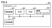
- FIG. 4 is a diagram showing a hardware configuration of the cloud server 400.
- FIGS. 3 and 4 an example of the configuration of each device in the monitoring system will be described with reference to FIGS. 3 and 4.
- the sensor box 100 includes a control device 101, a ROM (Read Only Memory) 102, a RAM (Random Access Memory) 103, a communication interface 104, a camera 105, a Doppler sensor 106, a wireless communication device 107, and a storage device. Includes 120.
- the control device 101 controls the sensor box 100.
- the control device 101 is composed of, for example, at least one integrated circuit.
- the integrated circuit is composed of, for example, at least one CPU (Central Processing Unit), at least one ASIC (Application Specific Integrated Circuit), at least one FPGA (Field Programmable Gate Array), or a combination thereof.
- An element such as an antenna (not shown) is connected to the communication interface 104.
- the sensor box 100 exchanges data with an external communication device via the antenna.
- External communication devices include, for example, a management server 200, a mobile terminal 300, an access point AP, a cloud server 400, and other communication terminals.
- the camera 105 is a near-infrared camera in one implementation example.
- Near-infrared cameras include IR (Infrared) floodlights that project near-infrared light. By using a near-infrared camera, an image showing the inside of the living room 900 can be taken even at night.
- the camera 105 is a surveillance camera that receives only visible light.
- a 3D sensor or a thermography camera may be used as the camera 105.
- the sensor box 100 and the camera 105 may be integrally configured or may be configured separately.
- the Doppler sensor 106 is, for example, a microwave Doppler sensor that radiates and receives radio waves to detect the behavior (operation) of an object in the living room 900. As a result, the biometric information of the resident 800 in the living room 900 can be detected.
- the Doppler sensor 106 radiates microwaves in the 24 GHz band toward the bed 901 of each room 900 and receives the reflected waves reflected by the resident 800. The reflected wave is Doppler-shifted by the operation of the resident 800.
- the Doppler sensor 106 can detect the respiratory state and heart rate of the resident 800 from the reflected wave.
- the wireless communication device 107 receives signals from the care call slave unit 500, the door sensor 510, the toilet sensor 520, the odor sensor 530, the vital sensor 540, and the microphone 550, and transmits the signals to the control device 101.
- the care call slave unit 500 includes a care call button 501, and when the care call button 501 is operated, a signal indicating that the operation has been performed is transmitted to the wireless communication device 107.
- Each of the door sensor 510, the toilet sensor 520, the odor sensor 530, and the vital sensor 540 transmits their respective detection outputs to the wireless communication device 107.
- the storage device 120 is a storage medium such as a hard disk or an external storage device.
- the storage device 120 stores a program executed by the control device 101 and various data used for executing the program.
- the various data may include behavioral information of the resident 800.
- At least one of the above programs and data may be stored in a storage device other than the storage device 120 as long as it is a storage device accessible to the control device 101.
- the storage device other than the storage device 120 is, for example, a storage area of the control device 101 (for example, a cache memory), a ROM 102, a RAM 103, and / or an external device (for example, a management server 200 or a mobile terminal 300). ..
- a pressure sensor 560 is provided in each living room 900.
- the pressure sensor 560 is connected to the sensor box 100, and the control device 101 may acquire the detection output of the pressure sensor 560.
- the installation mode of the pressure sensor 560 in the living room 900 will be described later with reference to FIG.
- the behavior information is, for example, information indicating that the resident 800 has executed a predetermined behavior.
- the predetermined action is "wake up” indicating that the resident 800 has awakened, "get out of bed” indicating that the resident 800 has left the bedding, and “fall” that indicates that the resident 800 has fallen from the bedding. , And four actions of "falling” indicating that the resident 800 has fallen.
- the control device 101 generates behavior information of the resident 800 associated with each room 900.
- the control device 101 generates the behavior information based on the image captured by the camera 105 installed in each living room 900. For example, the control device 101 detects the head of the resident 800 from the above image, and based on the time change of the size of the detected head of the resident 800, the resident 800 "wakes up” and “gets out of bed”. , Detects "falls” and “falls”.
- a specific example of generating behavioral information will be described in more detail.
- the storage device 120 stores the location area of the bed 901 in the living room 900, the first threshold value Th1, the second threshold value Th2, and the third threshold value Th3.
- the first threshold Th1 discriminates the size of the resident's head between the lying posture and the sitting posture in the location area of the bed 901.
- the second threshold value Th2 identifies whether or not the resident is in a standing position based on the size of the resident's head in the living room 900 excluding the area where the bed 901 is located.
- the third threshold value Th3 identifies whether or not the resident is in the lying position based on the size of the resident's head in the living room RM excluding the area where the bed 901 is located.
- the control device 101 extracts a moving object area from the target image as an area of a person of the resident 800. Extraction of the moving body region follows, for example, the background subtraction method or the frame subtraction method.
- the control device 101 further extracts the head region of the resident 800 from the extracted moving body region by pattern matching using a head model prepared in advance. For example, a circular or elliptical Hough transform technique is used to extract the head region. For pattern matching, a threshold value derived by a neural network learned for head detection may be used.
- the control device 101 detects "getting up", “getting out of bed”, “falling" and “falling" from the position and size of the extracted head.
- the position of the head extracted as described above is located within the location area of the bed 901, and the size of the head extracted as described above is the sitting position from the size of the lying posture.
- the first threshold Th1 is used to detect changes in the size of the head.
- the control device 101 is the case where the position of the head extracted as described above moves from the inside of the location area of the bed 901 to the outside of the location area of the bed 901, and the size of the head extracted as described above. It may be determined that the behavior "getting out of bed” has occurred when it detects that the size has changed from a certain size to the size of a standing posture.
- the second threshold Th2 is used to detect that the size of the head has changed to that in the standing position.
- the control device 101 is the case where the position of the head extracted as described above moves from the inside of the location area of the bed 901 to the outside of the location region of the bed 901, and the size of the head extracted as described above is large. If the size of the head changes from a certain size to the size of a lying posture, it may be determined that the behavior "fall" has occurred.
- the third threshold Th3 is used to detect that the size of the head changes to the size of the lying posture.
- the position of the head extracted as described above is located in the living room 900 excluding the area where the bed 901 is located, and the size of the extracted head is from a certain size to the lying posture.
- the third threshold Th3 is used to detect that the size of the head changes to the size of the lying posture.
- control device 101 of the sensor box 100 generates the behavior information of the resident 800.
- other elements may generate behavior information of the resident 800 by using the image in the living room 900.
- the management server 200 includes a control device 201, a ROM 202, a RAM 203, a communication interface 204, a display interface 205, an operation interface 207, and a storage device 220.
- the control device 201 controls the management server 200.
- the control device 201 is composed of, for example, at least one integrated circuit.
- the integrated circuit is composed of, for example, at least one CPU, at least one ASIC, at least one FPGA, or a combination thereof.
- Elements such as an antenna are connected to the communication interface 204.
- the management server 200 exchanges data with an external communication device via the antenna.
- External communication equipment includes, for example, a sensor box 100.
- the display interface 205 is connected to the display 206, and sends an image signal for displaying an image to the display 206 according to a command from the control device 201 or the like.
- the operation interface 207 is, for example, a USB (Universal Serial Bus) terminal and is connected to the input device 209.
- the operation interface 207 receives a signal indicating a user operation from the input device 209.
- An input device 209 such as a mouse, keyboard, touch panel, or other device capable of accepting user input operations.
- the storage device 220 is a storage medium such as a hard disk or an external storage device.
- the storage device 220 stores a program executed by the control device 201, but the program may be stored in another storage device accessible to the control device 201.
- the mobile terminal 300 includes a control device 301, a RAM 303, a communication interface 304, a display 305, an input device 306, and a built-in memory 320.
- the control device 301 controls the mobile terminal 300.
- the control device 301 is composed of, for example, at least one integrated circuit.
- An integrated circuit is composed of, for example, at least one CPU, at least one ASIC, at least one FPGA, or a combination thereof.
- Elements such as an antenna are connected to the communication interface 304.
- the mobile terminal 300 exchanges data with an external communication device via the antenna and the access point AP (FIG. 1).
- External communication equipment includes, for example, a sensor box 100, a management server 200, and the like.
- the display 305 is realized by, for example, an organic EL (Electro Luminescence) display.
- the input device 306 is realized, for example, by a touch sensor superimposed on the display 305.
- the touch sensor accepts various operations on the mobile terminal 300 by touch operations and outputs the contents of the operations to the control device 301.
- the built-in memory 320 is a storage medium such as eMMC (Embedded MultiMediaCard).
- the built-in memory 320 stores a program executed by the control device 301, but the program is stored in a storage device other than the built-in memory 320 if the storage device is accessible to the control device 301. You may be.
- the cloud server 400 includes a control device 401, a ROM 402, a RAM 403, a communication interface 404, and a storage device 420.
- the control device 401 controls the cloud server 400.
- the control device 401 is configured by at least one integrated circuit.
- the integrated circuit is composed of at least one CPU, at least one ASIC, at least one FPGA, or a combination thereof.
- Elements such as an antenna are connected to the communication interface 404.
- the cloud server 400 exchanges data with an external communication device via the antenna.
- the external communication device includes a sensor box 100 and a management server 200.
- the storage device 420 is a storage medium such as a hard disk or an external storage device.
- the storage device 420 stores a program executed by the control device 401, but the program may be stored in another storage device accessible to the control device 401.
- various "programs” may be provided by being incorporated into a part of an arbitrary program rather than as a single program.
- Various "programs” can be realized by the cooperation of any plurality of programs.
- the control device 101 of the sensor box 100 realizes the function described in the present specification by executing the first program
- the first program is a module of a part of the second program. You may be using. Even if the first program does not include some modules for realizing the function, if it mainly contributes to the realization of the function, it deviates from the purpose of the program for realizing the function. It's not something to do.
- some or all of the functions described herein may be implemented by dedicated hardware. Further, the device that provides the functions described herein may be provided by an external device in part or in whole as a so-called cloud service.
- FIG. 5 is a diagram showing an example of the installation mode of the pressure sensor in each living room 900.
- the pressure sensor 560 includes measuring sheets 560A, 560B, 560C.
- each of the measuring sheets 560A, 560B, and 560C is a capacitor-type pressure sensor arranged in a grid pattern.
- the pressure sensor 560 can output the distribution and total amount of pressure in each of the measuring sheets 560A, 560B, and 560C as a detection output.
- the measurement sheet 560A is installed on the bed 901. Thereby, the measuring sheet 560A can detect the pressure (and its distribution) applied to the bed 901.
- the measurement seat 560B is installed in the seat (seating position) of the wheelchair 905. Thereby, the measuring seat 560B can detect the pressure (and its distribution) applied to the seat of the wheelchair 905.
- the wheelchair 905 is located beside the bed 901.
- the measurement sheet 560B may include a communication interface for wireless communication. As a result, the measurement sheet 560B can communicate with the sensor box 100 regardless of whether the wheelchair 905 is installed in the living room 900 or outside the living room 900.
- the measurement sheet 560C is installed on the floor of the living room 900. Thereby, the measuring sheet 560C can detect the pressure (and its distribution) applied to the floor surface of the living room 900.
- the control device 101 of the sensor box 100 acquires the detection outputs of various sensors, derives an index for certifying the degree of care required of the resident 800, and outputs the derived index. In this sense, the sensor outputs a detection output representing the operation of the resident 800 toward the control device 101.
- sensors are, for example, a Doppler sensor 106, a camera 105, a care call handset 500, a door sensor 510, a toilet sensor 520, an odor sensor 530, a vital sensor 540, a microphone 550, and / or a pressure sensor 560.
- “derivative” is used as a general term for identification, acquisition, calculation, and the like.
- the control device 101 acquires data from the Doppler sensor 106 via the interface 106A.
- the control device 101 acquires data from the camera 105 via the interface 105A.
- the control device 101 acquires data from the care call slave unit 500, the door sensor 510, the toilet sensor 520, the odor sensor 530, the vital sensor 540, the microphone 550, and the pressure sensor 560 via the wireless communication device 107.
- each of the interface 106A, the interface 105A, and the wireless communication device 107 is an example of an interface in which the control device 101 acquires a detection output in the sensor box 100.
- the control device 101 uses the part of the detection output of the sensor corresponding to the unconscious movement of the resident 800 to derive information for certifying the degree of care required or the degree of support required (hereinafter referred to as the degree of care required certification).
- the certification of the degree of support required is collectively referred to as the certification of the degree of nursing care).
- the unconscious movement is, for example, a sleep movement (more specifically, a turning movement) or a reflexive movement (avoidance movement at the time of danger, etc.).
- the types of unconscious movements are not limited to those described above.
- An example of information on the degree of care required certification (information on the degree of care required or the paper end) is the ADL index.
- the control device 101 specifies the score of the item "turning over motion" as an ADL index. More specifically, the control device 101 identifies the number of times the resident 800 turns over for a given period (sleeping, from 8:00 pm to 5:00 the next morning, etc.) from the image in the living room 900, and the relevant person concerned. The score associated with the number of times is specified as the score of the item "turning over motion".
- the storage device 120 may store a conversion table as an example of information relating the number of times of turning over and the score.
- the control device 101 may obtain the score associated with the number of times by referring to the conversion table. In the present embodiment, the control device 101 may apply the number of times of turning over to a predetermined mathematical formula instead of the conversion table to obtain a score.
- the control device 101 as an index related to the reflexive behavior, is the time from the occurrence of a given event (for example, a call) to the reaction to the given event (for example, the generation of a responding voice, the reflection motion, etc.) (
- the reaction time) may be specified, the specified reaction time may be converted into a score, and the index may be specified from the score.
- the time from the start to the end of the retrospective motion (reflex action time) may be specified, the specified reflex action time may be converted into a score, and the index may be specified from the score.
- the control device 101 may identify that the resident has responded to a given event by identifying an action conforming to a predetermined pattern from a detection output such as an image from the camera 105, or the camera.
- the detection output such as an image from 105 may be applied to a trained machine learning model and specified by using the output of the machine learning model.
- the storage device 120 may store a conversion table as an example of information relating the reaction time to the score and / or information relating the reflex action time to the score.
- the control device 101 may obtain the score associated with the reaction time by referring to the conversion table.
- the control device 101 can specify the number of times of turning over in a given period, and derive an index of the item "turning over” based on the number of times.
- FIG. 6 is a flowchart of an example of processing in the control device 101 for deriving the index of the item “turning over operation”.
- the control device 101 performs the process of FIG. 6 by causing the processor to execute a given program.
- a given program may be stored in storage device 120.
- the storage device 120 is an example of a recording medium that non-temporarily stores a program for causing the control device 101 to perform the process of FIG.
- a given program is a storage device accessible to the control device 101 and may be stored in a storage device other than the storage device 120.
- the storage device other than the storage device 120 is an example of a recording medium that non-temporarily stores the program for causing the control device 101 to execute the process of FIG.
- step S600 the control device 101 acquires an image in the living room 900 for a given period for the index of the item “turning over motion” from the camera 105.
- the control device 101 may receive an image from the camera 105 in real time, or may receive an image from the camera 105 stored in a given storage device from the storage device.
- step S602 the control device 101 specifies the number of times the person turns over in the image acquired from the camera 105.
- the number of times of turning over is specified later with reference to FIG. 7.
- step S604 the control device 101 acquires an index corresponding to the number of times of turning motion specified in step S602.
- the control device 101 specifies the number of times of turning over in a given period, and the score associated with the number of times is specified as the score of the item "turning over".
- the storage device 120 may store a conversion table as an example of information relating the number of times of turning over and the score in a given period.
- the control device 101 may obtain the score associated with the number of times by referring to the conversion table.
- the conversion table is stored in, for example, the storage device 120.
- step S606 the control device 101 outputs the index acquired in step S604 and ends the process of FIG.
- the output destination may be an output device such as a display connected to the control device 101, or may be another information device (management server 200 or the like) with which the control device 101 can communicate.
- FIG. 7 is a diagram showing an example of skeletal information used for detecting the motion of turning over.
- FIG. 7 shows the skeleton information of a person identified by the control device 101 for a frame of an image from the camera 105.
- the outer shell OL1 represents the outer shell of the person
- the point P10 represents the position of the center of gravity of the person
- the points P11 and P12 represent the positions of both shoulders of the person.
- the control device 101 may count the number of times the resident turns over using the image from the camera 105. In counting the rolling motion, the control device 101 causes the person to be sideways (right or right) from the distance DF indicating that the distance between the shoulders of the person (resident) in the image is that the person is facing the front. When a change to the distance DS indicating that the object is facing the left) is detected, the count value may be updated by 1 addition.
- control device 101 extracts a portion corresponding to the period in which the distance between both shoulders changes from the distance DF to the distance DS from the image from the camera 105, and turns over using the image (frame) of the period. Identify the behavior of.
- control device 101 derives and outputs an index of the resident's turning motion.
- the control device 101 sets the period during which the resident is in a sleeping state based on the image from the camera 105 as the target period for deriving the index, instead of a predetermined predetermined period. It may be specified. This makes it possible for the resident to more reliably identify the rolling motion as an unconscious motion.
- the control device 101 may specify the period during which the resident is in a sleeping state, for example, based on the detection output from the Doppler sensor 106 and / or the detection output from the vital sensor 540. For example, the control device 101 may determine whether or not the resident is in a sleeping state depending on whether or not the mode of body movement specified based on the detection output of the Doppler sensor 106 is a sleeping state. good. The control device 101 may determine whether or not the resident is in a sleeping state depending on whether or not the heart rate specified based on the detection output of the vital sensor 540 is a sleeping heart rate.
- the control device 101 may update the count value of the turning motion by 1 when the distance between the shoulders of the person in the image changes from the distance DS to the distance DF. In this case, the control device 101 extracts a portion corresponding to the period in which the distance between both shoulders changes from the distance DS to the distance DF from the image from the camera 105, and uses the image (frame) of the period. Identify the action of one roll over.
- the control device 101 identifies the rolling motion by using the detection output from the measurement sheet 560A installed on the bed instead of the image from the camera 105 or in addition to the image from the camera 105. May be good. In this case, the control device 101 acquires the detection output from the measurement sheet 560A instead of or in addition to the control of step S600. Then, in step S602, the control device 101 uses the detection output from the measurement sheet 560A instead of the image from the camera 105 or in addition to the image from the camera 105, and the number of times the resident turns over. To identify.
- a pattern corresponding to a state in which a person on the bed is facing the front (hereinafter, also referred to as a “front pattern”) and a person on the bed are facing sideways.
- a pattern corresponding to a certain state (hereinafter, also referred to as a “horizontal pattern”) may be stored.
- the frontal pattern has a larger area on the measuring sheet 560A that detects pressure above a given value than the lateral pattern.
- control device 101 may update the count value of one rolling operation by 1 each time the detection output of the measurement sheet 560A changes from the front pattern to the sideways pattern.
- control device 101 may update the count value of one rolling operation by 1 each time the detection output of the measurement sheet 560A changes from the horizontal pattern to the front pattern.
- the control device 101 may derive an index related to a behavior (habitual behavior) that is naturally performed without being conscious by using the detection output from the sensor.
- the index related to habitual behavior may be, for example, an index derived based on the movement immediately after waking up from sleep (movement of getting up from the bed).
- the index related to habitual behavior may also be the item "wheelchair transfer motion” or the item “stand-up motion”.
- “Wheelchair transfer operation” is an action on the way to a purpose such as sitting in a wheelchair.
- the "transfer operation” may indicate an action of transferring from a given place such as a bed to a wheelchair, or conversely, moving from a wheelchair to a given place such as a bed. It may also indicate an action.
- the "standing motion” is an action in the middle of the action of walking. Subjects who do not need to receive much care or support may be too conscious of the previous behavior and may not be aware of the behavior in the middle. By analyzing these behaviors, it is possible to estimate whether or not the behavior includes acting.
- the derivation of each type of index will be described.
- FIG. 8 is a flowchart of an example of the process executed by the control device 101 for deriving the ADL index.
- the score of the item “wheelchair transfer operation” is derived as an example of the ADL index.
- the control device 101 performs the process of FIG. 8 by causing the processor to execute a given program.
- step S800 the control device 101 acquires an image corresponding to a certain period of time in the living room 900 from the camera 105.
- the control device 101 acquires an image of a period including a time zone in which the resident 800 is assumed to have transferred to a wheelchair in the living room 900, which is designated as an image corresponding to a certain time by the administrator of the watching system. You may.
- the control device 101 may acquire an image of each day as an image corresponding to a certain period of time. The control device 101 may sequentially acquire images from the camera 105.
- step S802 the control device 101 calculates the rotation angle of the human trunk in each frame of the image acquired in step S800.
- the control device 101 In calculating the rotation angle of the human trunk, the control device 101 first acquires the skeleton information of the person from the image.
- a well-known service for example, "User Local Posture Estimate AI" ⁇ https://humanpose-ai.userlocal.jp/>
- User Local Co., Ltd. is used to acquire the skeleton information of a person from an image. Will be done.
- the control device 101 identifies a line from the center of the head to the center of the chest from the acquired skeletal information, and calculates the rotation angle of the trunk as an angle formed by the line and a predetermined reference line. do.
- FIG. 9 is a diagram showing the flow of transfer from the bed to the wheelchair.
- the flow 700 shown in FIG. 9 includes images 701, 702, 703, 704 at four timings, and represents the flow of the movement of the resident to transfer from the bed to the wheelchair.
- Image 702 represents a timing state after image 701
- image 703 represents a timing state after image 702
- image 704 represents a timing state after image 703.
- each of the heads H1, H2, H3, and H4 represents the head of a person identified from the skeletal information in each of the images 701, 702, 703, and 704.
- Each of the chests C1, C2, C3 and C4 represents the chest of a person identified from the skeletal information in each of the images 701, 702, 703 and 704.
- FIG. 10 is a diagram showing the rotation angle of the trunk specified in each of the four images of FIG. 9.
- the flow 800 in FIG. 10 corresponds to the flow 700 in FIG.
- each of the frames 801, 802, 803, 804 corresponds to each of the images 701, 702, 703, 704 of FIG.
- the frame 801 shows a line L1 from the head H1 to the chest C1 and a reference line LS. Then, "85 °" is shown as the angle formed by the line L1 and the reference line LS.
- each of the frames 802,803,804 the lines from the heads H2, H3, H4 to the chests C2, C3, C4 are shown as lines L2, L3, L4, and the lines L2, L3, L3 are also shown.
- the reference line LS is commonly used for the information in the frames 801 to 804, that is, for the images 701 to 704.
- the reference line LS may be specified based on the contour of the bed in each frame (parallel to one straight line constituting the contour, etc.).
- step S804 whether or not the rotation angle of the trunk of the person has changed from the angle A1 to the angle A2 in the frame of the example constituting the image acquired in the step S800. To judge. The control device 101 repeats the control of step S804 until a change from the angle A1 to the angle A2 is observed in the rotation angle of the trunk of the person (NO in step S804), and the change from the angle A1 to the angle A2 is observed. If so (YES in step S804), control proceeds to step S806.
- FIG. 11 is a diagram showing an example of a mode of change in the rotation angle of the trunk.
- the vertical axis represents the rotation angle of the trunk
- the horizontal axis represents time.
- the line LM represents an example of a change over time in the rotation angle of the trunk identified in each frame of the image from the camera 105.
- the rotation angle of the trunk of the line LM changes from the angle A1 to the angle A2 between the time T1 and the time T2.
- the control device 101 advances control from step S804 to step S806.
- step S806 the control device 101 specifies the time (transfer time) required for the person in the image to transfer from the bed to the wheelchair.
- the control device 101 required the time (time from time T1 to time T2) until the rotation angle of the trunk changes from the angle A1 to the angle A2 in the image from the camera 105 for the transfer operation. Specify as time.
- step S808 the control device 101 acquires the score corresponding to the transfer time specified in step S806 as an index.
- the score means the score of the item "wheelchair transfer operation".
- the control device 101 may obtain the above-mentioned score by referring to the above-mentioned conversion table associating the length of time required for the transfer operation with the score.
- the conversion table is stored in, for example, the storage device 120.
- step S810 the control device 101 outputs the index acquired in step S808 and ends the process of FIG.
- the output destination may be an output device such as a display connected to the control device 101, or may be another information device (management server 200 or the like) with which the control device 101 can communicate.
- the control device 101 When the output destination is another information device, the control device 101 outputs an index via the communication interface 104.
- the communication interface 104 is an example of an output unit that outputs an index.
- the output unit may be included in the analysis unit for deriving the index.
- the control device 101 When the output destination is a display, the control device 101 outputs an index via a hardware element that is an interface between the display and the sensor box. In this sense, the hardware element is an example of an output unit that outputs an index.
- the control device 101 is a part from the image from the camera 105 until the rotation angle of the trunk of the person in each frame changes from the angle A1 to the angle A2 ( For example, the part corresponding to the period from time T1 to time T2 in FIG. 11) is extracted, and the time corresponding to the part (transfer time: for example, the time from time T1 to time T2 in FIG. 11) is specified.
- transfer time for example, the time from time T1 to time T2 in FIG. 11
- the control device 101 may impose additional conditions on the extraction of the above portion. For example, in the control device 101, when a change from the angle A1 to the angle A2 is observed in the rotation angle of the trunk, the person is located on the bed in the frame corresponding to the angle A1, and the frame corresponding to the angle A2. Then, the above-mentioned part may be extracted and the index may be derived on condition that the person is located outside the bed. That is, the control device 101 is, for example, when a person is located on the bed in both the frame corresponding to the angle A1 and the frame corresponding to the angle A2, or the frame corresponding to the angle A1 and the angle A2. If the person is located outside the bed in both of the corresponding frames, the index is not derived. As a result, the above index can be derived when the resident is exercising on the bed in the living room or when the resident is moving in a wheelchair, which is different from the movement to transfer to the wheelchair. Can be avoided.
- control device 101 may derive an index for the wheelchair transfer operation by specifying the speed of the transfer operation instead of the transfer time and acquiring a score corresponding to the speed.
- Velocity is specified, for example, as the reciprocal of the time it takes for the rotation angle of a person's trunk within each frame to change from a first angle to a second angle.
- the conversion table associates the speed with the score. In one implementation example, it is assumed that the higher the speed, the higher the corresponding score, but the relationship between the speed and the score is not limited to this.
- the conversion table is stored in, for example, the storage device 120.
- the control device 101 may derive an index based on the transfer time (or transfer speed) of one transfer operation.
- the control device 101 may derive an index based on a statistical value (for example, an average value) of the transfer time (or transfer speed) of a plurality of transfer operations.
- control device 101 may further output a statistical value of a measured value (index, transfer time, etc.) in each of a plurality of transfer operations as an auxiliary numerical value for the index.
- the output statistics are, for example, the minimum, maximum, mean, standard deviation, and / or variance of the measured values.
- control device 101 may output the standard deviation of the transfer time of the plurality of transfer operations together with the index in step S810. By checking the value of the standard deviation, the administrator of the watching system can infer whether or not the resident's behavior includes acting.
- control device 101 may output each transfer time for a plurality of transfer operations.
- the administrator of the watching system can infer that the transfer movement for the derivation of the indicator included the resident's performance due to the presence of extremely short and / or long transfer time times.
- FIG. 12 is a flowchart of another example of processing performed by the control device 101 for deriving the ADL index.
- the score of the item “wheelchair transfer operation” is derived as an example of the ADL index.
- the control device 101 performs the process of FIG. 8 by causing the processor to execute a given program.
- step S1000 the control device 101 is installed in the measurement seat 560A (installed on the bed) and the measurement seat 560B (installed in the wheelchair seat) corresponding to a certain period of time. ) To get the detected value.
- the phrase "corresponding to a certain period" in step S1000 can be interpreted as having the same meaning as in step S800.
- the control device 101 may sequentially acquire the detected values from the measurement sheets 560A and 560B.
- step S1002 the control device 101 checks the change in the detected value of the measurement sheet 560A installed on the bed at specific time (for example, 1 second), and the detected value is the value Pa at the specific time. Determine if it has dropped to. In one implementation example, the control device 101 determines that the detected value has decreased to the value Pa based on the fact that the detected value of the measurement sheet 560A has decreased from a value higher than the value Pa to the value Pa. If the control device 101 determines that the detected value has dropped to the value Pa (YES in step S1002), the control proceeds to step S1004, otherwise (NO in step S1002), the identification that has not been checked yet. The control of step S1002 is continued with respect to time.
- specific time for example, 1 second
- step S1004 the control device 101 determines that the detected value of the measuring seat 560A has dropped to the value Pa in step S1002, and then the detected value of the measuring seat 560B installed in the wheelchair seat is the value Pb. Determine if it has risen to. In one implementation example, the control device 101 determines that the detected value has increased to the value Pb based on the fact that the detected value of the measurement sheet 560B has increased from a value lower than the value Pb to the value Pb. When the control device 101 determines that the detected value of the measurement sheet 560B has increased to the value Pb after the detection value of the measurement sheet 560A has decreased to the value Pa (YES in step S1004), the control device 101 controls to step S1006. Proceed.
- control device 101 said that the detected value of the measuring sheet 560A increased to the value Pb within a predetermined time (for example, within 30 seconds) after the detected value of the measuring sheet 560A decreased to the value Pa. If it cannot be determined (NO in step S1004), control is returned to step S1002. As a result, the detected value of the measurement sheet 560A, which has not yet been targeted in step S1002, is targeted in step S1002.
- step S1006 the control device 101 takes time (transfer) from the detected values of the measurement sheet 560A and the measurement sheet 560B to the wheelchair transfer operation generated in the living room where the measurement sheets 560A and 560B are installed. Time) is specified. In one implementation example, the control device 101 uses the length of time from the time when the detected value of the measurement sheet 560A drops to the value Pa to the time when the detected value of the measurement sheet 560B reaches the value Pb as the transfer time. Identify.
- FIG. 13 is a diagram showing an example of changes in the detected values of the measurement sheet 560A and the measurement sheet 560B.
- the line La represents the time change of the detected value of the measurement sheet 560A
- the line Lb represents the time change of the detected value of the measurement sheet 560B.
- the vertical axis represents the value of the detected pressure
- the horizontal axis represents time.
- the control device 101 specifies the time (time Tx) from the time Ta to the time Tb as the transfer time.
- step S1008 the control device 101 acquires the score corresponding to the transfer time specified in step S1006 as an index of the item “wheelchair transfer operation”. Obtaining a score corresponding to the transfer time can be realized, for example, in the same manner as described for step S808.
- step S1010 the control device 101 outputs the index acquired in step S1008 and ends the process of FIG.
- the control device 101 receives the measurement sheet 560B after the detection value of the measurement sheet 560A drops to the value Pa from the detection output of the measurement sheets 560A and 560B.
- the detection output for the period until the detection value rises to the value Pb is extracted, the transfer time is specified based on the detection output, and the index (score) is derived and derived based on the specified transfer time. Output the index.
- the control device 101 can specify the speed of the rising motion and derive an index of the item “rising motion” based on the speed.
- FIG. 14 is a diagram showing an example of skeleton information used for detecting the rising motion.
- FIG. 14 shows the skeleton information of a person identified by the control device 101 for a frame of an image from the camera 105.
- the outer shell OL1 represents the outer shell of the person
- the point P10 represents the position of the center of gravity of the person
- the region H10 represents the region specified as the head of the person.
- the sensor box 100 including the camera 105 is installed on the ceiling CL of the living room 900. Therefore, the camera 105 takes a picture of the resident 800 in the living room 900 from above. Therefore, as the rising motion progresses, the distance between the head of the resident 800 and the camera 105 becomes shorter, and as a result, the area of the head becomes larger in the image captured by the camera 105.
- the control device 101 identifies the time required for the area of the area specified as the head of the person in the image taken by the camera 105 to change from the first area to the second area, and determines the time required for the time.
- the speed of the rising motion of the person may be specified based on the reciprocal. That is, the control device 101 extracts from the image from the camera 105 a portion where the area of the region specified as the head of the person changes from the first area to the second area, and the extracted portion is used. Based on this, the speed of the rising motion of the person may be specified.
- the storage device 120 may store a conversion table as an example of information relating the speed of the rising motion and the score.
- the control device 101 may acquire a score associated with the specified speed by referring to the conversion table, and output the acquired score as an index of the item “rising motion”.
- the conversion table is stored in, for example, the storage device 120.
- the higher the speed of the rising motion the higher the score, but the relationship between the speed and the score is not limited to this.
- the control device 101 may output a statistical value of a measured value (index, speed of rising operation, etc.) for each of a plurality of rising operations as an auxiliary numerical value for the index.
- the output statistics are, for example, the minimum, maximum, mean, standard deviation, and / or variance of the measured values.
- control device 101 may output the standard deviation of the above speed together with the index in step S810. By checking the value of the standard deviation, the administrator of the watching system can infer whether or not the resident's behavior includes acting.
- control device 101 may output the speed of each rise for a plurality of rise operations.
- the administrator of the watching system can infer that the presence of extremely slow and / or fast rising speed times included the resident's performance in the rising action for the derivation of the indicator.
- FIG. 15 is a diagram showing an example of skeletal information used for detecting walking motion.
- FIG. 15 shows the skeleton information of a person identified by the control device 101 for a frame of an image from the camera 105.
- the outer shell OL1 represents the outer shell of the person, and the point P10 represents the position of the center of gravity of the person.
- the control device 101 may specify the moving speed of the position of the center of gravity of the person in the image taken by the camera 105 as the speed of the walking motion of the person.
- the storage device 120 may store a conversion table as an example of information relating the speed of walking motion to the score.
- the control device 101 may acquire a score associated with the specified speed by referring to the conversion table, and output the acquired score as an index of the item “walking motion”.
- the conversion table is stored in, for example, the storage device 120.
- the control device 101 may specify the speed of the walking motion by using the detection output of the measurement sheet 560C.
- the control device 101 identifies the locus of the position where the measurement sheet 560C detects the pressure as the locus of movement of the resident in the living room 900, and specifies the moving distance of the resident from the locus of movement of the resident.
- the speed of the walking motion may be specified based on the specified distance traveled and the time required for the movement. In this case, the control device 101 determines the speed of the walking motion from the detection output of the measurement sheet 560C to the portion corresponding to the period in which the position where the measurement sheet 560C detects the pressure changes by a predetermined distance or more.
- the speed of the walking motion may be specified after being extracted as a part of.
- the higher the speed of the walking motion the higher the score, but the relationship between the speed and the score is not limited to this.
- the control device 101 may output a statistical value of a measured value (index, walking speed, etc.) for each of a plurality of walking movements as an auxiliary numerical value for the index.
- the output statistics are, for example, the minimum, maximum, mean, standard deviation, and / or variance of the measured values.
- control device 101 may output the standard deviation of the walking speed together with the index in step S810. By checking the value of the standard deviation, the administrator of the watching system can infer whether or not the resident's behavior includes acting.
- control device 101 may output the walking speed of each walking motion for each walking motion.
- the administrator of the watching system can infer that the presence of extremely slow and / or fast walking speed turns included the resident's performance in the walking motion for deriving the indicator.
- the control device 101 may specify the type of movement of the resident from the image in the living room 900 by using the machine learning model.
- the controller of the controller 101 functions as a discriminator by executing a program that realizes the algorithm of the machine learning model.
- FIG. 16 is a diagram showing an example of a machine learning model.
- the machine learning model 1500 includes a learner 1501 based on the LightGBM (Gradient Boosting) framework and a learner 1502 based on the LSTM (Long Short Term Memory) framework.
- the machine learning model shown in FIG. 16 is only an example, and any kind of model may be used to specify the type of movement of the resident.
- the learning device 1501 is subjected to learning processing using a plurality of frame images labeled according to the type of movement of the person. More specifically, in one example, the learner 1501 performs a learning process using a frame image labeled with any of the following nine types, so that the input frame image is subject to the learning process. It is configured to output the prediction result of the type of movement of the person in the frame image.
- the frame image is lying on the bed 901. Means to include the person who is.
- "Bed rest to bed rest” means that the frame image includes a person changing state from bed rest to bed rest in bed 901.
- the end seat is meant that the frame image includes a person sitting on the end in bed 901.
- “Standing from the end” means that the frame image includes a person in a state of being transferred from bed 901 to a wheelchair.
- “Wheelchair movement” means that the frame image includes a person moving in a wheelchair. "Walking from a standing position” means that the frame image includes a person who is in the process of changing the state from a stationary state to a walking state. “Walking” means that the frame image includes a walking person.
- the learning device 1502 is subjected to learning processing using a plurality of sets of frame images labeled according to the type of movement of the person.
- FIG. 17 is a diagram for explaining machine learning of the learner 1502.
- set 1600 represents an example of a set of frame images used for machine learning of the learner 1502.
- the set 1600 includes seven consecutive frame images 1601-1607.
- An example of the time difference corresponding to consecutive frame images is 0.4 seconds.
- the set 1600 is temporally labeled with the type of motion labeled in the central frame image 1604 and is input to the learner 1502. That is, the label attached to the frame image 1604 among the frame images 1601 to 1607 is used as the correct answer label.
- the label type includes, for example, a type corresponding to each of the above nine types (types (1) to (9)).
- the number of frame images included in one set described above, which frame image in the frame images included in one set is used as the label attached to the set, and consecutive frames.
- Each of the time differences in which the images correspond is just an example.
- the learner 1502 performs the learning process as described above, and by inputting a continuous frame image, the prediction result of the type of movement of the person in the specific frame image in the continuous frame image. Is configured to output.
- the machine learning model 1500 outputs the prediction result in two stages using the learning device 1501 and the learning device 1502 for each frame of the image from the camera 105. More specifically, the machine learning model 1500 uses the learner 1501 to output a prediction result of the type of operation of each frame. Then, the machine learning model 1500 inputs a set composed of a plurality of consecutive frames to the learner 1502 in the manner shown in FIG. The set of frames is input to the learner 1502 together with the prediction results of the learner 1501 for the plurality of frames constituting the set. More specifically, the set of frames is input to the learner 1502 together with the prediction result of a specific frame in the set (the time-centered frame in the set in the example of FIG. 17). By inputting a set of frames, the learner 1502 outputs a prediction result of the type of movement of the person for a specific frame in the set.
- the machine learning model 1500 outputs the prediction result output from the learner 1502 as the final prediction result.
- the machine learning model 1500 may correct the prediction result output from the learner 1502 and output the corrected prediction result as the final prediction result. More specifically, in the machine learning model 1500, when the learner 1502 outputs the same prediction result continuously for a given number of frames or more, the prediction output in each of the consecutive frames. The result is output as it is as the final prediction result. On the other hand, when the prediction result output for a certain frame of the learner 1502 is not continuous for a given number of frames including the frame, the machine learning model 1500 obtains the prediction result of the frame. It changes to another prediction result output by the learner 1502 for the consecutive frames before or after, and outputs the changed prediction result as the final prediction result.
- the machine learning model 1500 is configured to output the prediction result output by the learning device 1502 as it is as the final prediction result on condition that the learning device 1502 outputs the same prediction result continuously for 10 frames or more. It is assumed that it has been done. In such a case, the learner 1502 outputs the prediction result of the type (8) for 12 consecutive frames, then outputs the prediction result of the type (6) for one frame, and then continuously for 10 frames or more. When the prediction result of the type (8) is output, the machine learning model 1500 changes the prediction result to the type (6) for the frame to which the prediction result of the type (8) is given, and the prediction result after the change. Is output as the final prediction result.
- the control device 101 may extract a part of the image from the camera 105 in which frames of which the prediction result is type (5) are continuous and use it for deriving the ADL index of the item “wheelchair transfer operation”. good.
- the control device 101 may extract a portion of the image from the camera 105 in which frames whose prediction result is type (4) are continuous and use it for deriving the ADL index of the item “rising motion”.
- the control device 101 may extract a portion of the image from the camera 105 in which frames of which the prediction result is type (8) are continuous and use it for deriving the ADL index of the item “walking motion”.
- the control device 101 extracts a part of the image from the camera 105 in which frames whose prediction result is type (7) or type (8) is continuous, and uses it for deriving the ADL index of the item “walking motion”. You may.
- 100, 100A, 100B sensor box, 200 management server 560 pressure sensor, 560A, 560B, 560C measurement sheet, 701,702,703,704 image, 800,800A,800B resident, 801,802,803,804 frame , 900,900A, 900B living room, 901,901A,901B bed, 905 wheelchair, 1500 machine learning model, 1501,1502 learner, 1600 set, 1601,1604,1607 frame image.
Landscapes
- Health & Medical Sciences (AREA)
- Engineering & Computer Science (AREA)
- Medical Informatics (AREA)
- Biomedical Technology (AREA)
- Pathology (AREA)
- Epidemiology (AREA)
- General Health & Medical Sciences (AREA)
- Primary Health Care (AREA)
- Public Health (AREA)
- Alarm Systems (AREA)
- Measuring And Recording Apparatus For Diagnosis (AREA)
- Measurement Of The Respiration, Hearing Ability, Form, And Blood Characteristics Of Living Organisms (AREA)
Priority Applications (1)
| Application Number | Priority Date | Filing Date | Title |
|---|---|---|---|
| JP2022550427A JP7670062B2 (ja) | 2020-09-17 | 2021-08-24 | 情報処理装置、情報処理システム、プログラム、および記録媒体 |
Applications Claiming Priority (2)
| Application Number | Priority Date | Filing Date | Title |
|---|---|---|---|
| JP2020-156029 | 2020-09-17 | ||
| JP2020156029 | 2020-09-17 |
Publications (1)
| Publication Number | Publication Date |
|---|---|
| WO2022059438A1 true WO2022059438A1 (ja) | 2022-03-24 |
Family
ID=80776816
Family Applications (1)
| Application Number | Title | Priority Date | Filing Date |
|---|---|---|---|
| PCT/JP2021/030919 Ceased WO2022059438A1 (ja) | 2020-09-17 | 2021-08-24 | 情報処理装置、情報処理システム、プログラム、および記録媒体 |
Country Status (2)
| Country | Link |
|---|---|
| JP (1) | JP7670062B2 (https=) |
| WO (1) | WO2022059438A1 (https=) |
Citations (5)
| Publication number | Priority date | Publication date | Assignee | Title |
|---|---|---|---|---|
| JP2001250004A (ja) * | 1999-12-27 | 2001-09-14 | Nissetsu Engineering Co Ltd | 要介護度認定方法、要介護度認定システム、記録媒体及び、携帯端末制御機器 |
| JP2003144501A (ja) * | 2001-11-12 | 2003-05-20 | Keiki Imai | 要支援又は要介護度早見表及びケアプラン策定早見表 |
| JP2018029706A (ja) * | 2016-08-23 | 2018-03-01 | 株式会社デジタル・スタンダード | 端末装置、評価システム、およびプログラム |
| JP2019198695A (ja) * | 2019-08-21 | 2019-11-21 | 西日本電信電話株式会社 | 通知システム、通知装置、通知方法、及びプログラム |
| WO2020003952A1 (ja) * | 2018-06-26 | 2020-01-02 | コニカミノルタ株式会社 | コンピューターで実行されるプログラム、情報処理装置、および、コンピューターで実行される方法 |
-
2021
- 2021-08-24 WO PCT/JP2021/030919 patent/WO2022059438A1/ja not_active Ceased
- 2021-08-24 JP JP2022550427A patent/JP7670062B2/ja active Active
Patent Citations (5)
| Publication number | Priority date | Publication date | Assignee | Title |
|---|---|---|---|---|
| JP2001250004A (ja) * | 1999-12-27 | 2001-09-14 | Nissetsu Engineering Co Ltd | 要介護度認定方法、要介護度認定システム、記録媒体及び、携帯端末制御機器 |
| JP2003144501A (ja) * | 2001-11-12 | 2003-05-20 | Keiki Imai | 要支援又は要介護度早見表及びケアプラン策定早見表 |
| JP2018029706A (ja) * | 2016-08-23 | 2018-03-01 | 株式会社デジタル・スタンダード | 端末装置、評価システム、およびプログラム |
| WO2020003952A1 (ja) * | 2018-06-26 | 2020-01-02 | コニカミノルタ株式会社 | コンピューターで実行されるプログラム、情報処理装置、および、コンピューターで実行される方法 |
| JP2019198695A (ja) * | 2019-08-21 | 2019-11-21 | 西日本電信電話株式会社 | 通知システム、通知装置、通知方法、及びプログラム |
Also Published As
| Publication number | Publication date |
|---|---|
| JPWO2022059438A1 (https=) | 2022-03-24 |
| JP7670062B2 (ja) | 2025-04-30 |
Similar Documents
| Publication | Publication Date | Title |
|---|---|---|
| US11270799B2 (en) | In-home remote monitoring systems and methods for predicting health status decline | |
| US11516625B2 (en) | Systems and methods for mapping a given environment | |
| CN101632107A (zh) | 普适感测 | |
| WO2019013257A1 (ja) | 見守り支援システム及びその制御方法、プログラム | |
| US12400410B2 (en) | System and method for generating and visualizing virtual figures from pressure data captured using weight support devices for visualization of user movement | |
| JP7065447B2 (ja) | 情報処理方法、情報処理装置、及びプログラム | |
| CN108662728A (zh) | 信息处理方法、信息处理装置以及程序 | |
| JP7342863B2 (ja) | コンピュータで実行されるプログラム、情報処理システム、および、コンピュータで実行される方法 | |
| JP7371624B2 (ja) | コンピューターで実行されるプログラム、情報処理装置、および、コンピューターで実行される方法 | |
| JP7276336B2 (ja) | コンピュータで実行されるプログラム、情報処理システム、および、コンピュータで実行される方法 | |
| JP2021114021A (ja) | リハビリテーションを支援する情報の提供の方法およびリハビリテーション支援システム | |
| WO2022059438A1 (ja) | 情報処理装置、情報処理システム、プログラム、および記録媒体 | |
| JP7327397B2 (ja) | コンピューターで実行されるプログラム、情報処理システム、および、コンピューターで実行される方法 | |
| WO2020075675A1 (ja) | ケアシステムの管理方法および管理装置、ならびにプログラム | |
| WO2020009107A1 (ja) | 情報処理装置、センサーボックス、および、プログラム | |
| TWM625774U (zh) | 基於深度影像的被照護者行為分析的照護檢測系統 | |
| Uddin | Multimodal Systems for Independent Living | |
| JP7552185B2 (ja) | 情報処理装置、情報処理システム、およびプログラム | |
| JP2020091521A (ja) | センサーボックス、見守りシステム、およびプログラム | |
| WO2020075674A1 (ja) | ケアシステムの管理方法および管理装置、ならびにプログラム | |
| JP2024065638A (ja) | 睡眠パターンの安定性を表す指標を取得するためのコンピューターが実行する方法、プログラムおよび情報処理装置 | |
| JPWO2019244647A1 (ja) | コンピューターで実行されるプログラム、情報処理装置、および、コンピューターで実行される方法 | |
| JP2024167938A (ja) | 情報処理装置、情報処理プログラムおよび機械学習装置 | |
| JP2021196739A (ja) | 介助度合い推定方法、プログラム、および情報処理装置 | |
| Yuan | Context-aware real-time assistant architecture for pervasive healthcare |
Legal Events
| Date | Code | Title | Description |
|---|---|---|---|
| 121 | Ep: the epo has been informed by wipo that ep was designated in this application |
Ref document number: 21869125 Country of ref document: EP Kind code of ref document: A1 |
|
| ENP | Entry into the national phase |
Ref document number: 2022550427 Country of ref document: JP Kind code of ref document: A |
|
| NENP | Non-entry into the national phase |
Ref country code: DE |
|
| 122 | Ep: pct application non-entry in european phase |
Ref document number: 21869125 Country of ref document: EP Kind code of ref document: A1 |