WO2022054958A1 - 射出成形機 - Google Patents
射出成形機 Download PDFInfo
- Publication number
- WO2022054958A1 WO2022054958A1 PCT/JP2021/033653 JP2021033653W WO2022054958A1 WO 2022054958 A1 WO2022054958 A1 WO 2022054958A1 JP 2021033653 W JP2021033653 W JP 2021033653W WO 2022054958 A1 WO2022054958 A1 WO 2022054958A1
- Authority
- WO
- WIPO (PCT)
- Prior art keywords
- injection
- resin
- mold
- screw
- molding machine
- Prior art date
Links
- 238000001746 injection moulding Methods 0.000 title claims description 155
- 238000002347 injection Methods 0.000 claims abstract description 324
- 239000007924 injection Substances 0.000 claims abstract description 324
- 239000011347 resin Substances 0.000 claims abstract description 275
- 229920005989 resin Polymers 0.000 claims abstract description 275
- 238000000465 moulding Methods 0.000 claims abstract description 195
- 238000010992 reflux Methods 0.000 claims abstract description 106
- 238000010438 heat treatment Methods 0.000 claims abstract description 31
- 230000001737 promoting effect Effects 0.000 claims abstract description 14
- 230000002441 reversible effect Effects 0.000 claims description 62
- 230000036961 partial effect Effects 0.000 claims description 22
- 230000002093 peripheral effect Effects 0.000 claims description 15
- 230000003134 recirculating effect Effects 0.000 claims description 6
- 238000003860 storage Methods 0.000 claims description 6
- PCHJSUWPFVWCPO-UHFFFAOYSA-N gold Chemical compound [Au] PCHJSUWPFVWCPO-UHFFFAOYSA-N 0.000 claims 1
- 239000010931 gold Substances 0.000 claims 1
- 229910052737 gold Inorganic materials 0.000 claims 1
- 230000006870 function Effects 0.000 description 115
- 238000000034 method Methods 0.000 description 79
- 238000004519 manufacturing process Methods 0.000 description 40
- 230000008569 process Effects 0.000 description 40
- 238000001816 cooling Methods 0.000 description 21
- 230000001965 increasing effect Effects 0.000 description 14
- 238000005303 weighing Methods 0.000 description 14
- 238000010586 diagram Methods 0.000 description 13
- 230000006835 compression Effects 0.000 description 8
- 238000007906 compression Methods 0.000 description 8
- 230000006872 improvement Effects 0.000 description 8
- 238000003825 pressing Methods 0.000 description 8
- 230000008859 change Effects 0.000 description 7
- 238000005265 energy consumption Methods 0.000 description 7
- 239000002699 waste material Substances 0.000 description 7
- 230000009471 action Effects 0.000 description 6
- 230000006399 behavior Effects 0.000 description 6
- 230000007423 decrease Effects 0.000 description 6
- 230000004048 modification Effects 0.000 description 6
- 238000012986 modification Methods 0.000 description 6
- 238000005457 optimization Methods 0.000 description 6
- 238000007711 solidification Methods 0.000 description 6
- 230000008023 solidification Effects 0.000 description 6
- 230000007547 defect Effects 0.000 description 5
- 230000002950 deficient Effects 0.000 description 5
- 239000000463 material Substances 0.000 description 5
- 238000006073 displacement reaction Methods 0.000 description 4
- 230000000694 effects Effects 0.000 description 4
- 238000009825 accumulation Methods 0.000 description 3
- 239000008188 pellet Substances 0.000 description 3
- 230000002829 reductive effect Effects 0.000 description 3
- 229920001169 thermoplastic Polymers 0.000 description 3
- 239000004416 thermosoftening plastic Substances 0.000 description 3
- 238000007872 degassing Methods 0.000 description 2
- 238000000605 extraction Methods 0.000 description 2
- 238000000265 homogenisation Methods 0.000 description 2
- 230000003287 optical effect Effects 0.000 description 2
- MFOUDYKPLGXPGO-UHFFFAOYSA-N propachlor Chemical compound ClCC(=O)N(C(C)C)C1=CC=CC=C1 MFOUDYKPLGXPGO-UHFFFAOYSA-N 0.000 description 2
- 230000002411 adverse Effects 0.000 description 1
- 239000000470 constituent Substances 0.000 description 1
- 230000003247 decreasing effect Effects 0.000 description 1
- 238000005516 engineering process Methods 0.000 description 1
- 230000002708 enhancing effect Effects 0.000 description 1
- 230000009969 flowable effect Effects 0.000 description 1
- 239000010720 hydraulic oil Substances 0.000 description 1
- 238000002156 mixing Methods 0.000 description 1
- 239000003921 oil Substances 0.000 description 1
- 239000004033 plastic Substances 0.000 description 1
- 238000003908 quality control method Methods 0.000 description 1
- 230000009467 reduction Effects 0.000 description 1
- 238000004904 shortening Methods 0.000 description 1
- 230000000087 stabilizing effect Effects 0.000 description 1
Images


Classifications
-
- B—PERFORMING OPERATIONS; TRANSPORTING
- B29—WORKING OF PLASTICS; WORKING OF SUBSTANCES IN A PLASTIC STATE IN GENERAL
- B29C—SHAPING OR JOINING OF PLASTICS; SHAPING OF MATERIAL IN A PLASTIC STATE, NOT OTHERWISE PROVIDED FOR; AFTER-TREATMENT OF THE SHAPED PRODUCTS, e.g. REPAIRING
- B29C45/00—Injection moulding, i.e. forcing the required volume of moulding material through a nozzle into a closed mould; Apparatus therefor
- B29C45/17—Component parts, details or accessories; Auxiliary operations
- B29C45/46—Means for plasticising or homogenising the moulding material or forcing it into the mould
- B29C45/47—Means for plasticising or homogenising the moulding material or forcing it into the mould using screws
- B29C45/50—Axially movable screw
- B29C45/52—Non-return devices
Definitions
- the present invention relates to an injection molding machine that injects and fills a mold that has been molded by a predetermined mold clamping force with a resin at a predetermined injection pressure to perform molding.
- This injection molding machine ensures a high degree of quality and homogeneity of molded products even for low-viscosity resins that are sensitive to temperature, pressure, etc., and simplifies molding conditions and makes setting easy.
- the purpose is to improve mass productivity and economic efficiency by facilitating quality control and shortening the molding cycle time.
- a mold clamping device By using a mold clamping device that enables natural compression of the resin at least as the resin in the mold solidifies, a predetermined mold gap is created between the movable mold and the fixed mold at the time of injection filling in advance, and good product molding is possible.
- the molding injection pressure and the molding mold clamping force are obtained and set, and at the time of production, the mold clamping device is molded by the molding mold clamping force, the molding injection pressure is set as the limiter pressure, and the injection device is driven to drive the mold.
- the injection filling of the resin is performed.
- a molded product when a molded product is produced by an injection molding machine, it is usually molded by setting various molding conditions such as injection speed, injection pressure, resin temperature, etc., which match the type of molded product.
- the obtained molded product has some molding defects, and in particular, there are some molded products in which molding defects are likely to occur depending on the type of the molded product and the like.
- molding using recycled pellet material which has a tendency to have a non-uniform pellet shape compared to normal pellets due to the mixing of high-cycle molded products, crushed materials, etc., which have a short plasticization time and do not easily transfer sufficient heat to the resin.
- Products, molded products with a large injection capacity that require large-capacity plasticization at one time, etc. are particularly prone to molding defects and a decrease in yield rate (non-defective product rate).
- the present invention aims to provide an injection molding machine that solves the problems existing in such background technology.
- the injection molding machine M includes a mold clamping device Mc that clamps a mold 2 composed of a fixed mold 2c and a movable mold 2 m with a predetermined mold clamping force in order to solve the above-mentioned problems.
- An injection molding machine including an injection device Mi that injects and fills a resin with a predetermined injection pressure into the molded mold 2 and a molding machine controller C that controls the mold clamping device Mc and the injection device Mi.
- the resin R in front of the screw head portion 4s is injection-filled in the mold 2 and at the same time, a predetermined amount of resin is injected.
- the injection molding machine M according to the first embodiment has a predetermined amount in the range of 10-60 [%] with respect to the capacity of the resin R to be injection-filled in the mold 2 according to a preferred embodiment of the invention. It is desirable to select.
- the screw head portion 4s is provided with at least one recirculation passage 11 ... It can be configured by providing an injection pressure additional setting function unit Fs that sets a predetermined amount higher than the injection pressure Pi when the screw does not return, or a reverse rotation control function unit Fc that reversely rotates the screw 4 is provided.
- the reverse rotation control function unit Fc may be provided with the reverse rotation setting function unit Fcs for the period in which the screw 4 is rotated in the reverse direction and the rotation speed.
- a mold clamping device a mold clamping device Mc that enables natural compression of the resin R at least as the resin R in the mold 2 is solidified is used, and a movable mold is previously used in the molding machine controller C at the time of injection filling.
- a predetermined mold gap Lm is generated between the 2m and the fixed mold 2c, and the injection pressure (hereinafter, molding injection pressure) Pi that can be molded into a good product and the mold clamping force (hereinafter, molding mold clamping force) Pc that can be molded into a good product are obtained.
- the mold clamping device Mc is molded by the molding mold clamping force Pc, and the molding injection pressure Pi is set as the limiter pressure Ps to drive the injection device Mi to drive the resin R with respect to the mold 2.
- a control function for injection filling can be provided.
- the injection molding machine M is a mold clamping device that clamps a mold 2 composed of a fixed mold 2c and a movable mold 2 m by a predetermined mold clamping force in order to solve the above-mentioned problems.
- An injection molding machine including Mc, an injection device Mi that injects and fills a resin with a predetermined injection pressure to the molded mold 2, and a molding machine controller C that controls the mold clamping device Mc and the injection device Mi.
- the injection molding machine M according to the second embodiment can use an injection device provided with a shut-off nozzle (or valve nozzle) 51 as the injection device Mi according to a preferred embodiment of the invention.
- a mold clamping device a mold clamping device Mc that enables natural compression of the resin R at least as the resin R in the mold 2 is solidified is used, and a movable mold is previously used in the molding machine controller C at the time of injection filling.
- a predetermined mold gap Lm is generated between 2 m and the fixed mold 2c, and the molding injection pressure Pi capable of forming a good product and the molding mold clamping force Pc capable of forming a good product are obtained and set.
- the clamping device Mc By molding the clamping device Mc and setting the molding injection pressure Pi as the limiter pressure Ps, it is possible to provide a control function for driving the injection device Mi to inject and fill the mold 2 with the resin R.
- the plasticization promotion step Wi3 when the plasticized storage resin R is refluxed, it may be refluxed by the forward pressure control function for the screw 4 or it may be refluxed by the reverse rotation control function for the screw 4. good.
- an auxiliary plasticizing treatment (S121) for securing the amount of the reflux resin Rm can be performed before the substantial plasticization promoting treatment (S122) is carried out.
- an auxiliary plasticizing treatment part for performing the auxiliary plasticizing treatment and a plasticization promoting treatment part for performing the plasticization promoting treatment are set, and the auxiliary plasticizing treatment part (S201) and the plasticization promoting treatment part (S202) based on this setting are set.
- the combination step of the above can be repeated within a preset number of times N or within an allowable time of the plasticization promoting step Wi3.
- the amount (predetermined amount) of the reflux resin Rm is 10-60 [with respect to the capacity of the resin R to be injected and filled in the mold 2. %] Can be selected to achieve a good balance between production efficiency and yield rate in the production of molded products. Therefore, both should be optimized from the viewpoint of ensuring production efficiency and yield rate. be able to.
- At least one reflux passage 11 in which the resin Rm is refluxed to the screw head portion 4s when the partial reflux injection function portion 5 is configured is configured. If the screw head portion 4s is provided, it can be realized by changing the screw head portion 4s or by performing additional processing, so that it can be easily and inexpensively carried out, and can be easily applied to an existing injection molding machine. can.
- the injection pressure Pi at the time of molding is set to the injection pressure Pi when the resin R does not recirculate.
- the injection pressure additional setting function unit Fs which is set higher by a predetermined size, is provided, the amount of the recirculation resin Rm (recirculation amount) can be injected even when the recirculation passage 11 ... Is provided. Since it can be arbitrarily set by the pressure additional setting function unit Fs, the recirculation amount can be easily set and the influence on the original amount (filling amount) of the resin R to be injected and filled in the mold 2 is avoided. can do.
- the reverse rotation control function unit Fc that rotates the screw 4 in the reverse direction is provided. Since it is not necessary to change the shape of the screw 4 itself, it becomes possible to recirculate the screw 4 by the control process, further facilitating the implementation, and further enhancing the versatility.
- the reverse rotation control function unit Fc when the reverse rotation control function unit Fc is provided, if the reverse rotation setting function unit Fcs for setting the period for reverse rotation of the screw 4 and the rotation speed is provided, the recirculation amount of the recirculation resin Rm can be reduced. Since it can be set by the reverse rotation setting function unit Fcs, an arbitrary recirculation amount can be easily set, and it is possible to avoid an influence on the original filling amount to be injected and filled with respect to the mold 2.
- a mold clamping device Mc that enables natural compression of the resin R at least as the resin R in the mold 2 is solidified is used as the mold clamping device, and the molding machine controller C is used in advance.
- a predetermined mold gap Lm is generated between the movable mold 2m and the fixed mold 2c at the time of injection filling, and the injection pressure (hereinafter, molding injection pressure) Pi that can mold a good product and the mold clamping force that can mold a good product (hereinafter, molding mold clamping). Force) Pc is obtained and set, and at the time of molding, the mold clamping device Mc is molded by the molding mold clamping force Pc, and the molding injection pressure Pi is set as the limiter pressure Ps to drive the injection device Mi.
- the injection molding machine M according to the second embodiment if an injection device provided with a shut-off nozzle (or valve nozzle) 51 is used for the injection device Mi, the nozzle port 3ne is required. Can be shut off, so that the plasticization promotion step Wi3 can be performed during the cooling step Wc4, the mold opening step Wc5, and the molded product taking-out step Wc6. As a result, it becomes possible to carry out a sufficient plasticization promotion treatment in terms of time, and the injection molding machine M according to the present invention can be carried out more reliably and satisfactorily.
- the injection process Wi2 is completed if the resin R is recirculated by the forward pressure control function for the screw 4. Later, after the resin in the mold 2 is sufficiently solidified, the forward pressing force on the screw 4 can be increased in a state where the molded product in the mold 2 is not affected. It can be recirculated using pressure. Therefore, it can be easily carried out by providing the screw head portion 4s with a slight reflux passage or a reflux passage having an opening / closing function, which does not cause reflux depending on the molding injection pressure Pi.
- the resin R when the resin R is recirculated in the injection molding machine M according to the second embodiment, the resin R is recirculated by the forward pressure control function and the reverse rotation control function for the screw 4. Since the recirculation amount can be adjusted by controlling the reverse rotation of the screw 4, any recirculation amount of the resin Rm can be easily and accurately set by selecting conditions such as the period for reverse rotation and the rotation speed.
- the amount of the reflux resin Rm is before the substantial plasticization promoting treatment (S122) is executed.
- the auxiliary plasticizing treatment (S121) to secure Only by performing the auxiliary plasticizing treatment (S121), the required amount of reflux resin Rm can be secured.
- the auxiliary plasticization treatment part for performing the auxiliary plasticization treatment and the plasticization promotion for carrying out the plasticization promotion treatment are performed.
- a processing part is set, and the combination process of the auxiliary plasticization processing part (S201) and the plasticization promotion processing part (S202) based on this setting is performed within a preset number of times N or within the allowable time of the plasticization promotion process Wi3.
- the cooling time is relatively long, for example, as in a large molded product, the cooling time can be effectively utilized by performing such a repeating process.
- the plasticization treatment for the resin R can be performed more uniformly and precisely, which can contribute to further quality improvement and yield rate improvement of the molded product.
- FIG. 1 A cross-sectional side view showing a part of an injection device (virtual line circle A part in FIG. 1) provided in the injection molding machine according to the first embodiment of the same embodiment.
- a bar graph showing the magnitude of various physical quantities with and without reflux by the injection molding machine.
- a flowchart for explaining a molding procedure by an injection molding method using the injection molding machine Explanatory drawing showing the behavior of the resin in the plasticization process of the injection molding machine, Explanatory drawing showing the behavior of the resin in the molding process of the injection molding machine, Relationship diagram of time vs.
- a cross-sectional side view showing a part of an injection device (virtual line circle A part in FIG. 1) provided in the injection molding machine according to the second embodiment of the same embodiment.
- Relationship diagram of screw reverse rotation and recirculation rate when using the same injection molding machine A cross-sectional side view showing a part of the injection device (virtual line circle A part in FIG. 1) according to the modified example of the first embodiment of the same embodiment.
- M is an injection molding machine, which includes an injection device Mi and a mold clamping device Mc.
- the injection device Mi is provided with a heating cylinder 3 having an injection nozzle 3n at the front end and a hopper 21 at the rear, and a screw 4 is inserted inside the heating cylinder 3 and a screw is driven at the rear end of the heating cylinder 3.
- the portion 23 is arranged.
- the screw drive unit 23 includes an injection cylinder (hydraulic cylinder) 24 containing a single rod type injection ram 24r, and the ram rod 24rs projecting forward of the injection cylinder 24 is coupled to the rear end of the screw 4.
- a shaft of a metering motor (oil motor) 25 attached to the injection cylinder 24 is spline-coupled to the rear end of the injection ram 24r.
- Reference numeral 26 denotes an injection device moving cylinder that moves the injection device Mi forward and backward to touch the nozzle with respect to the mold 2 or release the nozzle. As a result, the injection device Mi can touch the injection nozzle 3n to the mold 2 and inject and fill the molten (plasticized) resin R (FIG. 5) in the cavity of the mold 2.
- the mold clamping device Mc is a direct pressure type hydraulic mold clamping device that displaces the movable mold 2 m by the drive ram 27r of the mold clamping cylinder (hydraulic cylinder) 27.
- This mold clamping device Mc is provided with a fixed plate 28 whose position is fixed and is arranged apart from each other, and is a movable plate slidably mounted on a plurality of tie bars 29 ... erected between the fixed plate 28 and the mold clamping cylinder 27. 30 is provided.
- the tip of the ram rod 27rs protruding forward from the mold clamping cylinder 27 is fixed to the movable plate 30.
- the fixed mold 2c is attached to the fixed plate 28, and the movable mold 2m is attached to the movable plate 30.
- the fixed mold 2c and the movable mold 2m form the mold 2.
- the mold clamping cylinder 27 can open and close the mold 2 and perform mold clamping.
- this mold clamping device Mc can naturally compress the resin R at least as the resin R in the mold 2 solidifies. be.
- the injection molding machine M includes the hydraulic circuit 35 shown in FIG. 1, and the hydraulic circuit 35 includes a variable discharge type hydraulic pump 36 and a valve circuit 37 which are hydraulic drive sources, and drives and controls the hydraulic pump 36.
- a pump circuit 38 is provided. Since the hydraulic pump 36 has a built-in swash plate (not shown), if the inclination angle (swash plate angle) of the swash plate is increased, the stroke of the pump piston is increased, the discharge flow rate can be increased, and the swash plate can be increased. If the angle is made small, the stroke of the pump piston becomes small, and the discharge flow rate can be reduced. Therefore, if the swash plate angle is set to a predetermined angle, it is possible to set a fixed discharge flow rate in which the discharge flow rate (maximum capacity) is fixed to a predetermined size.
- the discharge port of the hydraulic pump 36 is connected to the primary side of the valve circuit 37, and the secondary side of the valve circuit 37 is the injection cylinder 24, the measuring motor 25, the mold clamping cylinder 27, and the ejector in the injection molding machine M. It is connected to the cylinder 31 and the injection device moving cylinder 26. Therefore, the valve circuit 37 includes a switching valve (solenoid valve) connected to the injection cylinder 24, the measuring motor 25, the mold clamping cylinder 27, the ejector cylinder 31, and the injection device moving cylinder 26, respectively. Each switching valve is composed of one or more valve parts, necessary accessory hydraulic parts, etc., and at least the injection cylinder 24, the measuring motor 25, the mold clamping cylinder 27, the ejector cylinder 31, and the injection device movement. It has a switching function related to supply, stop, and discharge of hydraulic oil to the cylinder 26.
- the pump circuit 38 can change the discharge flow rate and the discharge pressure by controlling the pump motor (servo motor) of the variable discharge type hydraulic pump 36, and based on this, the above-mentioned injection cylinder 24, measuring motor 25, It is possible to control the drive of the mold clamping cylinder 27, the ejector cylinder 31, and the injection device moving cylinder 26, and also to control each operation process in the molding cycle.
- the pump capacity can be set to the fixed discharge flow rate (maximum capacity) of a predetermined size, and the fixed discharge flow rate can be set. Since the discharge flow rate and the discharge pressure can be changed based on the flow rate, easy and smooth control can be performed.
- the injection molding machine M includes a control system 41 shown in FIG.
- the control system 41 has a control function for executing a molding process in a specific molding mode.
- a predetermined mold gap Lm is generated between the movable mold 2m and the fixed mold 2c at the time of injection filling, and the molding injection pressure Pi capable of molding a good product and the molding mold clamping force Pc capable of molding a good product are obtained in advance.
- the mold clamping device Mc is molded by the molding mold clamping force Pc, the molding injection pressure Pi is set as the limiter pressure Ps, and the injection device Mi is driven to inject the resin R into the mold 2. It is a molding method that fills.
- the control system 41 includes a molding machine controller main body 42c and a molding machine controller C having a display 42d attached to the molding machine controller main body 42c.
- the molding machine controller main body 42c has a computer function having built-in hardware such as a CPU and an internal memory, and a control program (software) for executing various arithmetic processing and various control processing (sequence control) in the attached internal memory 42m. ) Is included in the program area 42mp for storing various programs, and the data area 42md for storing various data (databases) is included. Therefore, the software for executing the above-mentioned specific molding mode is stored in the program area 42mp, and can be made to function as the specific molding mode function unit Fa.
- the display 42d includes a display main body 42dd and a touch panel 42dt attached to the display main body 42dd, and the display main body 42dd and the touch panel 42dt are connected to the molding machine controller main body 42c via a display interface (not shown). Therefore, various setting operations, selection operations, and the like can be performed by the touch panel 42dt.
- various sensors 43 including a mold gap sensor for detecting at least the mold gap Lm and various switches 44 are connected to the molding machine controller main body 42c, and the pump circuit 38 and the valve circuit 37 described above are connected to the molding machine controller main body 42c. do.
- the injection molding machine M advances a partial recirculation injection function unit 5, that is, a screw 4 housed in a heating cylinder 3 of the injection device Mi, which constitutes a main part of the present invention.
- a partial recirculation injection function unit 5 that recirculates through the inner side and / or the outer peripheral portion side of the screw head portion 4s to the screw main body portion 4 m side behind the screw head portion 4s.
- the molding machine controller C stores software for partially functioning the reflux injection function unit 5, and the software allows the injection pressure additional setting function unit Fs, which will be described later, to be stored.
- the reverse rotation control function unit Fc and the reverse rotation setting function unit Fc can be made to function respectively.
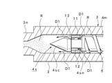
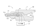
- FIG. 2 is an extraction enlarged view of a part of the injection device Mi in the injection molding machine M shown in FIG. 1, that is, the virtual line circle A part, and includes the partial reflux injection function part 5 according to the first embodiment. A part of the injection device Mi is shown.
- reference numeral 4 denotes a screw, which has a spiral screw flight 4f on the peripheral surface of the screw main body 4 m and a screw head portion 4s at the front end of the screw 4.
- the illustrated screw head portion 4s has a conical tip portion 4sc at the front end, and the rear end surface of the conical tip portion 4sc is attached to the front end surface of the screw main body portion 4m via the mounting shaft portion 4sj arranged in the axial direction Ds.
- a cylindrical check valve portion 4sn that can be moved back and forth is arranged between the conical tip portion 4sc and the screw main body portion 4m.
- the function of the check valve in the molding mode by a general injection molding machine is as follows. First, in the weighing step, the check valve moves to the front open position as the resin moves because the measuring is performed so that the resin moves from the screw main body side to the front of the screw head portion. That is, the resin is allowed to move forward. Further, in the injection process, the measured resin pressure acts backward, so that the check valve moves to the rear closed position. As a result, the backflow of the resin is blocked by the check valve. Therefore, the shape of the check valve is cylindrical, and the outer peripheral surface of the check valve comes into contact with the inner peripheral surface of the heating cylinder so that there is almost no gap and the check valve is inwardly formed. , The flowable resin passage of the resin is blocked.
- the entire check valve portion 4sn is formed into a cylindrical shape, and the reflux resin Rm is formed on the outer peripheral surface thereof.
- the reflux passage 11 is formed by a linear groove parallel to the axial direction Ds, and the size of the cross-sectional area of the reflux passage 11 is such that the amount of the reflux resin Rm (reflux amount) is injection-filled in the mold 2. It is desirable to select it so that it is in the range of 10-60 [%] with respect to the capacity of the resin R. With this selection, it is possible to strike a good balance between production efficiency and yield rate in the production of molded products. Therefore, it is possible to optimize both from the viewpoint of ensuring production efficiency and yield rate. can.
- 12 indicates a resin passage provided between the inner peripheral surface of the check valve portion 4sn and the outer peripheral surface of the mounting shaft portion 4sj, and 13 ... Are a plurality formed on the outer peripheral surface of the conical tip portion 4sc.
- the resin passage of is shown. Therefore, the resin passages 13 ... Are notched at equidistant positions in the circumferential direction.
- the resin passage 12 and the resin passage 13 are blocked.
- the molding machine controller C is provided with an injection pressure additional setting function unit Fs capable of changing the molding injection pressure Pi (limiter pressure Ps) described later.
- the injection pressure additional setting function unit Fs has at least a function of setting the injection pressure Pi at the time of molding higher by a predetermined magnitude with respect to the molding injection pressure Pi when the resin R does not recirculate.
- the recirculation amount of the recirculation resin Rm can be arbitrarily set by the injection pressure additional setting function unit Fs even when the recirculation passage 11 ... Is provided. Therefore, the recirculation amount can be easily set, and the influence on the original amount (filling amount) of the resin R to be injection-filled with respect to the mold 2 can be avoided. Therefore, it is desirable that the injection pressure Pi at the time of recirculating molding is set so as not to affect the original molding by the molding injection pressure Pi at the time of non-refluxing.
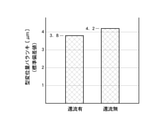
- FIG. 3 shows the magnitudes of various physical quantities at the time of molding when the resin R does not reflux (without reflux) and when a predetermined amount of refluxed resin Rm refluxes (with reflux).
- the injection peak pressure Pp corresponds to the limiter pressure Ps described later. Therefore, in the example, the injection peak pressure Pp (limiter pressure Ps) when there is no reflux is 50.5 [MPa], whereas the injection molding machine M according to the present embodiment is used with reflux.
- the injection molding method the case where the value is set to 52.5 [MPa], which is a slightly larger value than that without reflux, is shown.
- the injection peak pressure Pp (limiter pressure Ps) can be set by the injection pressure additional setting function unit Fs.
- the injection capacity Qi with no reflux increased to 71.2 [cubic centimeters]
- the injection stroke Xi of the screw at the time of injection is 44.8 [mm] when there is no reflux, whereas it becomes 61.4 [mm] when there is reflux. The result is shown.
- the injection pressure additional setting function for setting the injection pressure Pi at the time of molding higher by a predetermined magnitude with respect to the injection pressure Pi when the resin R does not recirculate. If the part Fs is provided, the recirculation amount of the recirculation resin Rm can be arbitrarily set by the injection pressure additional setting function unit Fs even when the recirculation passage 11 ... Is provided, so that the recirculation amount can be easily set. In addition, it is possible to avoid an influence on the original amount (filling amount) of the resin R to be injection-filled with respect to the mold 2.
- the specific molding mode used in the injection molding method of the injection molding machine M according to the present embodiment is preset.
- the basic molding procedure of this specific molding mode is the same as the procedure described in the above-mentioned Patent Document 1 (International Publication WO2011 / 161899) already proposed by the present applicant.
- the injection pressure which is the injection condition on the injection device Mi side
- the injection pressure can be set based on the ability (driving force) of the injection device Mi.
- the mold clamping force which is the mold clamping condition on the mold clamping device Mc side
- the mold clamping force can be set based on the capacity (driving force) of the mold clamping device Mc.
- the molding injection pressure Pi to be used at the time of production is obtained by performing the optimization processing for the initially set injection pressure
- the molding mold clamping force Pc to be used at the time of production is obtained by performing the optimization processing for the initially set mold clamping force.
- the mold clamping force and injection pressure can be optimized as follows. First, trial molding is performed using the initially set mold clamping force and injection pressure. When the mold clamping force is set to a large value, burrs do not occur, and sink marks, warpage, and degassing conditions tend to be defective or defective.
- the size of the mold gap Lm between the fixed mold 2c and the movable mold 2 m is not shown. It is acquired by a mold gap sensor (reflection type optical sensor or the like), displayed on the waveform display unit on the screen of the display 42d, and the quality of the molded product is observed.
- a mold gap sensor reflection type optical sensor or the like
- FIG. 7 shows the change state of the mold gap Lm displayed on this waveform display unit.
- the mold 2 starts to open at the to time point, and the maximum mold gap Lmp is generated at the tp time point. After that, it is gradually displaced in the closing direction, and finally settles in the remaining mold gap Lmr and stabilizes.
- the above-mentioned predetermined mold gap Lm (about 0.03-0.30 [mm]) is generated between the mobile mold 2m and the fixed mold 2c at the time of injection filling, and good product molding becomes possible.
- the molding injection pressure Pi can be set on the condition that Specifically, the injection pressure can be appropriately changed to select a size before the resin R does not normally fill the mold 2. Further, the obtained molding injection pressure Pi is set as the limiter pressure Ps with respect to the injection pressure at the time of production.
- the injection pressure additional setting function unit Fs is used to set the injection pressure Pi at the time of molding higher than the injection pressure Pi at the time of no reflux by a predetermined magnitude.
- a slightly larger value (52.5 [MPa]) was set as the injection pressure Pis at the time of molding with respect to the injection pressure Pi of 50.5 [MPa], and this injection pressure Pis was set as the limiter pressure Ps.
- the mold clamping force satisfying the above-mentioned conditions can be selected.
- the selected mold clamping force is set as the molding mold clamping force Pc when the mold is compacted with the mold 2 at the time of production.
- the magnitudes of the mold clamping force and the injection pressure may be arbitrarily set by the operator, or may be automatically or semi-automatically obtained while using the auto-tuning function provided in the injection molding machine M and the like.
- the resin R is plasticized based on the processing procedure of the specific molding mode, which is the basic molding method of the injection molding machine M according to the present embodiment (step S1).
- this plasticization treatment includes a plasticization promotion treatment.
- the metering motor 25 of the injection device Mi is rotationally driven by the control of the hydraulic pump 36 and the switching of the valve circuit 37.
- the specific molding mode does not require a weighing step for accurately measuring the resin R as in the molding method using a general molding mode. That is, since the injection treatment in the specific molding mode only needs to perform the injection operation until the cavity is filled with the resin R, it is sufficient to carry out a large amount of the resin R in the plasticizing step. In other words, the weighing operation in a general weighing process is performed, but the weighing control for obtaining an accurate weighing value becomes unnecessary.
- a partial recirculation operation by the recirculation injection function unit 5 is included, and a part of the remaining portion of the plastically accumulated resin R (recirculation resin Rm), that is, the injection resin amount (R). ), In order to recirculate the reflux amount (Rm) in the range of 10-60 [%], secure a plasticization treatment amount that is more than double the volume (1 shot amount) of the molded product. Is desirable.
- FIG. 5 shows the behavior of the resin R during the plasticization treatment.
- the screw 4 rotates at a set rotation speed and period. Since the resin R is transferred forward by the rotation of the screw 4, the resin R on the 4 m side of the screw main body portion 4 m is accumulated forward through the screw head portion 4s as shown by arrows D1 ...
- the check valve portion 4 sn moves to the front open position shown in FIG. 5, so that the resin R on the screw main body 4 m side is a check valve. It reaches the front of the conical tip portion 4sc through the resin passage 12 inside the portion 4sn and the resin passage 13 of the conical tip portion 4sc.
- the plasticized resin R is gradually accumulated in the heating cylinder 3 in front of the conical tip portion 4sc, and the screw 4 moves backward with the accumulation.
- step S2 the mold clamping cylinder 27 of the mold clamping device Mc is driven, and the mold clamping force becomes the set molding mold clamping force Pc. Tighten (step S2).
- the injection cylinder 24 of the injection device Mi is driven by switching the valve circuit 37 and controlling the hydraulic pump 36, and the injection process of the resin R is started for the mold 2 (step S3).
- the screw 4 may be advanced by the rated operation, and the speed control for the screw 4 is unnecessary.
- the plasticized and melted resin R in the heating cylinder 3 is filled into the cavity of the mold 2 through the injection nozzle 3n as shown by the arrow D2 in FIG. 6 (step S4).
- injection pressure Pis injection pressure
- the injection pressure Pis injection pressure
- the injection pressure is maintained (limited) at the limiter pressure Ps.
- step S3 the resin R accumulated in front of the screw 4 is injected and filled in the mold 2 and at the same time, the partial reflux injection function unit 5 is used. Due to the function, a predetermined amount of the reflux resin Rm that becomes a part of the resin R is gradually refluxed to the screw main body 4m side behind the screw head portion 4s (step SN). That is, since the screw 4 moves forward at the time of injection, the check valve portion 4sn moves to the rear closed position due to the resin pressure in the front.
- the resin passage 12 inside the check valve portion 4sn is blocked, but the reflux resin Rm, which is a part of the resin R accumulated in front of the screw head portion 4s, is shown in FIG. 6 due to the injection pressure Pis.
- the screw passes through the gap between the outer peripheral surface of the conical tip portion 4sc of the screw head portion 4s and the inner peripheral surface of the heating cylinder 3, and further, the reflux passage 11 ... on the outer peripheral surface of the check valve portion 4sn. It is refluxed to the 4 m side of the main body.
- step S7 when the cavity of the mold 2 is filled with the resin R, the mold 2 is pressed against the resin R, and a mold gap Lm (FIG. 7) is generated between the fixed mold 2c and the movable mold 2m (step S7). ).
- This mold gap Lm is generated based on the molding mold clamping force Pc and the molding injection pressure Pi (injection pressure Pis) set in advance.
- the injection time set in advance elapses from the start of injection, the injection filling of the resin R to the mold 2 is completed, so that the application of the molding injection pressure Pi (injection pressure Pis) is stopped or reduced.
- the substantial injection step is completed, and the reflux action is also terminated accordingly (step S8).
- the resin R Upon completion of the injection step (refluxing action), the resin R is plasticized (step S9).
- a predetermined amount of refluxed resin Rm is mixed on the front side of the screw main body 4 m, that is, a part of the reflux resin Rm of the primary plasticized resin R accumulated in front of the screw 4 is mixed. Since the screw is returned to the 4 m side and mixed, the resin R in which the reflux resin Rm is mixed is subjected to the plasticization treatment. Therefore, even when the resin R having insufficient plasticization is accumulated in front of the screw 4, the replasticization treatment is performed, and the plasticization is further promoted.
- step S10 the resin R is solidified with the passage of time, and the resin R is naturally compressed with the solidification (step S10). That is, since the capacity decreases due to the solidification of the resin R, natural compression is performed by the pressure action due to the elastic return of the mold 2 (particularly the movable mold 2 m) so as to follow the decrease in the capacity.
- the mold clamping cylinder 27 is driven by the switching of the valve circuit 37 and the control of the hydraulic pump 36, the mold is opened by retracting the movable mold 2 m, and the ejector cylinder 31 is opened. It is driven and the molded product adhered to the movable mold 2 m is projected (steps S11 and S12). As a result, the molded product is taken out, and one molding cycle is completed. After that, when the next molding is continued, processing such as mold clamping, injection, and cooling is performed in the same manner (steps S13, S2 ).
- FIG. 8 shows the variation in the amount of mold displacement when reflux is performed by the injection molding method using the injection molding machine M according to the present embodiment (first embodiment) and the mold displacement when reflux is not performed (without reflux).
- a comparison diagram of the standard deviation values of the amount variation is shown. That is, FIG. 8 shows the variation of the maximum value Lmp of the mold gap Lm in FIG. 7 when 30 molded products are molded. According to this, the standard deviation value without reflux is 4.2 [ ⁇ m], while the standard deviation value with reflux is 3.8 [ ⁇ m], which is about 11 [%]. Improvement was seen. This means that the homogenization of the plasticized resin R was further enhanced, and the yield rate corresponding to the rate of improvement was obtained for the yield rate of the molded product.
- the screw 4 housed in the heating cylinder 3 of the injection device Mi is moved forward.
- the resin R in front of the screw head portion 4s at the front end portion of the screw 4 is injection-filled into the mold 2, and at the same time, a predetermined amount of the reflux resin Rm that becomes a part of the resin R is injected into the reflux passage 11 in the screw head portion 4s. Since the return is made to return to the screw main body 4 m side behind the screw head portion 4s through ..., the yield rate of the final molded product can be significantly increased, and in particular, the conventional limit yield rate can be further increased.
- a mold clamping device Mc capable of spontaneously compressing the resin R at least as the resin R in the mold 2 solidifies.
- a predetermined mold gap Lm is generated between the movable mold 2m and the fixed mold 2c at the time of injection filling, and the molding injection pressure Pi that can be molded into a good product and the molding mold clamping force Pc that can be molded into a good product are obtained and set in advance.
- the mold clamping device Mc is molded by the molding mold clamping force Pc, the molding injection pressure Pi is set as the limiter pressure Ps, and the injection device Mi is driven to inject and fill the mold 2 with resin.
- the injection molding method by the injection molding machine M according to the present invention can be applied to the specific molding mode in which the weighing process does not exist, that is, the specific molding mode which is hardly affected by the state on the injection device Mi side. It can be implemented as an optimum form from the viewpoint of improving the production efficiency and reducing the production cost as described above, and further contributing to the avoidance of resource loss and the avoidance of waste of energy consumption.
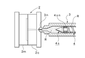
- FIG. 9 is an extraction enlarged view of a part of the injection device Mi in the injection molding machine M shown in FIG. 1, that is, the virtual line circle A part, and includes the partial reflux injection function part 5 according to the second embodiment. A part of the injection device Mi is shown.
- the injection device Mi of the second embodiment has the same basic configuration as the injection device Mi provided in the injection molding machine M shown in FIG. 2 of the first embodiment.
- the reflux resin is additionally provided with the reverse rotation control function unit Fc that rotates the screw 4 in the reverse direction to the molding machine controller C shown in FIG. It enables the promotion of reflux and quantitative control of Rm. Therefore, software for realizing the reverse rotation control function unit Fc is stored in the program area 42mp of the internal memory 42m. If such a reverse rotation control function unit Fc is provided when the partial reflux injection function unit 5 is configured, it is not necessary to change the shape of the screw 4 itself. It can be realized, further facilitated implementation, and can be more versatile.
- the reverse rotation control function unit Fc is provided with a reverse rotation setting function unit Fcs for setting the period and rotation speed for rotating the screw 4 in the reverse direction. If such a reverse rotation setting function unit Fcs is provided, the recirculation amount of the recirculation resin Rm can be set by the reverse rotation setting function unit Fcs, so that an arbitrary recirculation amount can be easily set and the mold 2 can be set. On the other hand, it is possible to avoid the influence on the original filling amount of injection filling.
- the screw 4 when setting the period for reverse rotation of the screw 4 and the rotation speed, the screw 4 is moved forward by the molding injection pressure Pi, and the resin R in front of the screw head portion 4s is injected into the mold 2 at the same time.
- a predetermined amount of recirculated resin Rm that becomes a part of the resin R that is, an amount of recirculated resin Rm selected in the range of 10-60 [%] with respect to the capacity of the resin R to be injection-filled in the mold 2 is screwed. It is desirable to set the period and the rotation speed at which the resin passage 12 on the inner side of the head portion 4s can be returned to the screw main body portion 4m side behind the screw head portion 4s.
- FIG. 9 the same parts as those in FIGS. 1 and 2 are designated by the same reference numerals to clarify their configurations and omit detailed description thereof.
- the flowchart shown in FIG. 10 shows specific processing in step SN in the flowchart shown in FIG. 4, and the entire molding procedure is performed according to the flowchart shown in FIG. That is, the injection molding method using the injection molding machine M according to the second embodiment is preset in the same manner as the specific molding mode in the first embodiment, and the specific processing procedure at the time of production is shown in FIG. Except for the processing content of step SN shown, steps S1-S11 are basically the same. Therefore, in the following, only the processing portion according to the second embodiment in the step SN will be described in detail with reference to FIG.
- step S3 in the flowchart shown in FIG. 4 is being performed.
- the injection cylinder 24 of the injection device Mi is driven to start the injection process of the resin R on the mold 2, and the resin R accumulated in front of the screw 4 is filled in the mold 2 (step). S4).
- the screw 4 is controlled to rotate in the reverse direction by the reverse rotation control function unit Fc at a predetermined timing, for example, the timing when the injection process starts or the timing when the predetermined set time has elapsed (step SN1).
- a predetermined timing for example, the timing when the injection process starts or the timing when the predetermined set time has elapsed (step SN1).
- the screw 4 rotates in the reverse direction in the direction of the arrow Drn at the rotation speed set by the reverse rotation setting function unit Fcs.
- the reflux of a part of the resin R existing on the screw head portion 4s side accumulated in front of the screw head portion 4s to the screw main body portion 4m side is promoted (step SN2).
- step SN3 and SN4 the reverse rotation control is stopped.
- a mold gap Lm is generated by injection filling, and when the injection process is completed, solidification of the resin R progresses with the passage of time, and the resin R naturally accompanies this solidification.
- the same processing (behavior) as in the first embodiment is performed, such as compression (steps S5, S6, S7 ).
- the partial reflux injection function unit 5 can perform the same operation (function) as that of the first embodiment. In addition to being able to enjoy the same basic effects as those of the first embodiment, it is possible to enjoy the effects of promoting the reflux action, which is more than that of the first embodiment.
- FIG. 11 shows the relationship between the screw rotation and the recirculation amount when the injection molding method of the injection molding machine M in the second embodiment is used.
- the reflux amount can be arbitrarily controlled such that the screw rotation and the reflux amount can be proportional to each other. can.
- FIG. 12 and 13 show modified examples of the first embodiment and the second embodiment.
- the first embodiment shown in FIG. 2 illustrates the screw head portion 4s using the cylindrical check valve portion 4sn, but the screw head using the ball-shaped check valve portion 4sn as shown in FIG. 12 is illustrated.
- the portion 4s may be used, and various forms of the check valve portion 4sn and the screw head portion 4s can be applied, and the configuration and type thereof are not limited.
- 51 indicates a resin passage.
- FIG. 12 is a modification of the first embodiment, and the basic configuration of the injection molding machine M and the basic processing procedure of the injection molding method are the same as those of the first embodiment described above.
- FIG. 13 is a modified example of the first embodiment or the second embodiment, and the basic configuration of the injection molding machine M and the basic processing procedure of the injection molding method are described in the first embodiment or the second embodiment described above. It will be the same as the embodiment.
- the third embodiment is the injection molding machine M according to the second embodiment of the present invention.
- the first embodiment or the second embodiment including the above-mentioned modification shows the injection molding machine M when the "injection step” and the "recirculation step” are executed at the same time, while the third embodiment shows the "injection step”.
- the injection molding machine M in the case where only the “recirculation step” is independently executed after the completion of the injection molding machine M is shown.
- the molding machine controller C controls the injection device Mi at the time of molding, and the screw 4 in the heating cylinder 3 is rotated to plasticize the resin in the heating cylinder 3 Wi1.
- Wi2 equipped with a control function for sequentially executing the plasticization promotion step Wi3 in which a part of the remaining portion of the resin R plasticized and accumulated after the completion of this injection step Wi2 is refluxed to the rear of the screw head portion 4s as a reflux resin Rm. ing.
- the molding machine controller C has a function of refluxing the plasticized and accumulated resin R in the plasticization promotion step Wi3, that is, a part of the resin R accumulated in front of the screw head portion 4s (reflux resin).
- Software for realizing control functions is stored.
- the pressurization control function is a reflux method in which the resin R flows backward by performing pressurization control to increase the forward pressing force on the screw 4.
- the pressurization control function the molded product in the mold 2 (after the gate seal) or after the cooling step after the injection step Wi2 is completed, such as after the resin R in the mold 2 is sufficiently solidified (after the gate seal). In the solidified state where the resin) is not affected, the pressure of the resin R accumulated in front of the screw head portion 4s can be increased to a size required for reflux.
- the screw head portion 4s may be provided with a slight recirculation passage that does not cause recirculation depending on the molding injection pressure Pi, or may be provided with a recirculation passage having an opening / closing function. Therefore, the amount of resin to be refluxed (the amount of refluxed resin) can be relatively easily implemented by increasing or decreasing the pressing force or setting the pressurizing time.
- the reverse rotation control function is a reflux method in which the resin R is returned to the rear by rotating the screw 4 in the reverse direction, and basically functions in combination with the above-mentioned pressurization control function.
- the amount of recirculation can be adjusted by controlling the screw 4 to rotate in the reverse direction. Therefore, the amount of recirculated resin can be set by selecting conditions such as the period for reverse rotation and the rotation speed, which can be more easily carried out, and can be arbitrarily changed by changing the period for reverse rotation of the screw 4 and the rotation speed. The amount of recirculation can be set easily and accurately. It is also possible to select and use either the pressurization control function or the reverse rotation control function.
- the injection pressure which is the injection condition on the injection device Mi side
- the injection pressure can be set based on the ability (driving force) of the injection device Mi.
- the mold clamping force which is the mold clamping condition on the mold clamping device Mc side
- the mold clamping force can be set based on the capacity (driving force) of the mold clamping device Mc.
- the molding injection pressure Pi to be used at the time of production is obtained by performing the optimization processing for the initially set injection pressure
- the molding mold clamping force Pc to be used at the time of production is obtained by performing the optimization processing for the initially set mold clamping force.
- the mold clamping force and injection pressure can be optimized as follows. First, trial molding is performed using the initially set mold clamping force and injection pressure. When the mold clamping force is set to a large value, burrs do not occur, and sink marks, warpage, and degassing conditions tend to be defective or defective.
- the size of the mold gap Lm between the fixed mold 2c and the movable mold 2 m is not shown. It is acquired by a mold gap sensor (reflection type optical sensor or the like), displayed on the waveform display unit on the screen of the display 42d, and the quality of the molded product is observed.
- a mold gap sensor reflection type optical sensor or the like
- FIG. 14 shows change data of the mold gap Lm displayed on this waveform display unit.
- FIG. 14 shows a range (band) of the maximum value and the minimum value in 30 molding shots.
- the basic change is that the mold 2 starts to open at the to time point after the start of injection, and the maximum mold gap Lmp occurs at the tp time point. After that, it gradually changes in the closing direction, and finally settles in the remaining mold gap Lme and stabilizes.
- the above-mentioned predetermined mold gap Lm (about 0.03-0.30 [mm]) is generated between the mobile mold 2m and the fixed mold 2c at the time of injection filling, and good product molding becomes possible.
- the molding injection pressure Pi can be set on the condition that Specifically, the injection pressure can be appropriately changed to select a size before the resin R does not normally fill the mold 2. Further, the obtained molding injection pressure Pi is set as the limiter pressure Ps with respect to the injection pressure at the time of production. On the other hand, by repeating these trial moldings by changing the conditions, the mold clamping force satisfying the above-mentioned conditions can be selected.
- the selected mold clamping force is set as the molding mold clamping force Pc when mold clamping is performed by the mold 2 at the time of production.
- the magnitudes of the mold clamping force and the injection pressure may be arbitrarily set by the operator, or may be automatically or semi-automatically obtained while using the auto-tuning function provided in the injection molding machine M and the like.
- a plasticizing treatment is performed on the resin (material) (step S21).
- the step of performing this plasticizing process is the plasticizing step Wi1 shown in FIG.
- the metering motor 25 of the injection device Mi is rotationally driven by the control of the hydraulic pump 36 and the switching of the valve circuit 37.
- the screw 4 shown in FIG. 9 rotates forward over the set rotation speed and period. Since the resin R is transferred forward by the forward rotation of the screw 4, the resin R on the side of the screw main body 4 m is accumulated forward through the screw head portion 4s while being plasticized. At this time, the resin R moves forward from the screw body 4 m side, so that the check valve portion 4sn moves to the front open position. Therefore, the resin R on the screw body 4 m side is the check valve portion 4sn. It reaches the front of the conical tip 4sc through the inner resin passage 12 and the resin passage 13 of the conical tip 4sc. As a result, the plasticized resin R is gradually accumulated as the plasticized resin R in the heating cylinder 3 in front of the conical tip portion 4sc, and the screw 4 moves backward with this accumulation. ..
- the specific molding mode does not require a weighing step for accurately measuring the resin R as in the molding method using a general molding mode. That is, since the injection treatment in the specific molding mode only needs to perform the injection operation until the cavity is filled with the resin R, it is sufficient to carry out a large amount of the resin R in the plasticizing step. In other words, the weighing operation in a general weighing process is performed, but the weighing control for obtaining an accurate weighing value becomes unnecessary.
- step S22 by controlling the hydraulic pump 36 and switching the valve circuit 37, the mold clamping cylinder 27 of the mold clamping device Mc is driven, and the movable mold 2 m is moved in the mold closing direction (step S22).
- This operation is the mold closing step Wc1 shown in FIG.
- the mold clamping process is executed for the mold 2 so that the mold clamping force becomes the set molding mold clamping force Pc (step S23).
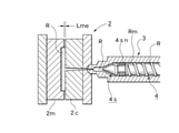
- This operation is the mold clamping step Wc2 shown in FIG. Further, FIG. 18 shows this state.
- the injection cylinder 24 of the injection device Mi is driven by switching the valve circuit 37 and controlling the hydraulic pump 36, and the injection process of the resin R is started for the mold 2 (step S24).
- the injection step Wi2 shown in FIG. 15 is performed.
- the screw 4 may be advanced by the rated operation, and speed control and pressure control for the screw 4 are unnecessary.
- the plasticized and melted resin R in the heating cylinder 3 is filled in the cavity of the mold 2 through the injection nozzle 3n (step S25).
- the injection pressure increases with the filling of the resin R (step S26).
- control for maintaining the limiter pressure Ps that is, control for preventing overshoot is performed, and the injection pressure is maintained (limited) to the limiter pressure Ps (step). S27). Therefore, in the injection operation, substantial one-pressure control is performed.
- step S28 the natural gap generation step Wc3 shown in FIG. 15 proceeds.
- This mold gap Lm is generated based on the molding mold clamping force Pc and the molding injection pressure Pi set in advance. This state is shown in FIG. The figure shows an image in which the maximum mold gap Lmp is generated as the mold gap Lm.
- the mold 2 side shifts to the cooling process Wc4 in which the cooling process is performed for the preset cooling time.
- the resin R is solidified with the passage of time, and the resin R is naturally compressed with the solidification (steps S30 and S31). That is, since the capacity decreases due to the solidification of the resin R, natural compression is performed by the pressure action due to the elastic return of the mold 2 (particularly the movable mold 2 m) so as to follow the decrease in the capacity.
- FIG. The figure shows an image in which the residual mold gap Lme is generated as the mold gap Lm.
- the plasticization promotion step Wi3 shown in FIG. 15 is executed at a preset timing (step S32).
- the auxiliary plasticization treatment for the resin (material) is performed for the predetermined auxiliary plasticization time T1 set in advance (step S121).
- the reason for this is that at the end stage of the injection process, the amount of the thermoplastic accumulation resin R accumulated in front of the screw 4 becomes small, so that the amount of recirculation is secured by performing the auxiliary plasticization treatment for the auxiliary plasticization time T1.
- the auxiliary plasticizing treatment may be an amount (total amount) in the plasticizing step Wi1 or may be a part thereof.
- the auxiliary plasticization time T1 to be set may be set according to a predetermined auxiliary plasticization position with respect to the screw 4.
- the resin R in the mold 2 (including the gate and the like) is solidified to some extent, and even if a high forward pressure is applied to the screw 4 by the pressurizing control function, the front is forwarded. It is possible to set a length at which the resin R does not flow, or a length that does not affect the resin R (molded product) in the mold 2 even if the screw 4 is controlled to rotate in the reverse direction by the reverse rotation control function. desirable.
- the substantial plasticization promotion step Wi3 is performed. That is, the reverse rotation control function and / or the pressurization control function described above for the screw 3 is executed (step S122).
- the pressurization control function drives the injection cylinder 24 to control the screw 4 to apply a forward pressing force.
- the pressing force at this time is set higher than the molding injection pressure Pi (limiter pressure Ps), so that it is possible to return to the rear.
- the start of applying the pressing force is the timing at which the resin R does not flow forward even if a high pressing force is applied forward, that is, at least by starting the cooling step Wc4 in the mold 2, the gate seal or the like. Is performed, and the molded product (resin R) is not affected.
- the plasticized and accumulated resin R is refluxed to the rear of the screw head portion 4s through the gap between the screw head portion 4s and the heating cylinder 3. Then, the reflux resin Rm that has flowed back to the rear of the screw head portion 4s is added to and mixed with the resin R on the screw main body portion 4m side. After that, when the plasticization promotion processing time T2 has elapsed, the plasticization promotion control (pressurization control) is stopped (steps S123 and S124). That is, the plasticization promotion step Wi3 using the pressurization control function is completed.
- the plasticization promotion treatment time T2 and the pressing pressure are preferably higher than the completion of the cooling treatment and the injection pressure Pi from the viewpoint of ensuring the production efficiency and the yield rate.
- the screw head portion 4s be provided with a slight reflux passage or a reflux passage with an opening / closing function in which reflux does not occur depending on the molding injection pressure Pi.
- step S122 when the reverse rotation control function is performed, in addition to the pressurization control function, the measuring motor 25 is driven and the screw 4 is controlled to rotate in the reverse direction at a preset rotation speed (step S122).
- the reflux of the plasticized storage resin R through the screw head portion 4s, which is a backflow, to the rear of the screw head portion 4s is promoted.
- the reflux resin Rm that has flowed back through the screw head portion 4s is added to and mixed with the resin R on the screw main body portion 4m side behind the screw head portion 4s.
- the plasticization promotion control reverse rotation control
- FIG. 20 shows a state in which the screw 4 is advanced and the target return amount is returned to the rear of the screw head portion 4s.
- step S33 the plasticization process by the plasticization step Wi1 is performed (step S33).
- the reflux resin Rm is mixed on the front side of the screw main body 4 m, that is, a part of the resin R that has been subjected to the primary plasticization treatment accumulated in front of the screw 4 is used as the reflux resin Rm and the screw main body 4 m. Since it is returned to the side and mixed, the resin R in which the reflux resin Rm is mixed is subjected to the plasticization treatment. Therefore, even when the insufficiently plasticized resin R and the refluxed resin Rm are accumulated in front of the screw 4, the replasticization treatment is performed, and the plasticization is further promoted.
- step S34 the mold opening step Wc5 shown in FIG.
- step S35 the molded product take-out step Wc6 shown in FIG.
- each process such as mold closing, mold clamping, injection, and cooling is performed in the same manner. It is performed sequentially (steps S36, S22 ).
- FIG. 14 shows the relationship between the time t [t] and the mold gap Lm [mm] in the injection step Wi2 by the injection molding method using the injection molding machine M according to the third embodiment, and in particular, 30 molded products are shown.
- the change data of each mold gap Lm ... During molding that is, the range (band) of the maximum value and the minimum value in 30 molding shots is shown, and the band Bi shown by the solid line corresponds to the third embodiment.
- the band Br shown by the virtual line indicates the case without recirculation, so to speak. According to this, when there is reflux, the variation of the mold gap Lm ...
- the relationship between the reverse rotation of the screw and the amount of recirculation by the injection molding method using the injection molding machine M according to the third embodiment is the same as in FIG. 11 described above.
- the recirculation of the resin R can be promoted and quantitatively controlled, so that the reverse rotation amount of the screw and the recirculation amount can be made proportional to each other. Can be controlled arbitrarily.
- This modification uses an injection molding machine M (injection device Mi) provided with the shut-off nozzle 61 shown in FIG. 22.
- the exemplary shut-off nozzle 61 has a known structure, in FIG. 22, 37 is the valve circuit shown in FIG. 1, and 62 is the nozzle port at the tip of the injection nozzle 3n due to the switching operation of the valve circuit 37.
- a shut-off valve that opens and closes 3ne, 62v is a shaft-shaped valve body, 62c is a drive cylinder that moves the valve body 62v forward and backward in the opening direction (rear) or closing direction (front), and 63 is a resin passage.
- the same parts as those in FIG. 9 described above are designated by the same reference numerals to clarify their configurations and omit detailed description thereof.
- the nozzle opening 3ne can be shut off as needed, so that the plasticization promotion step Wi3 is also performed during the cooling step Wc4, the mold opening step Wc5, and the molded product take-out step Wc6. It can be performed. As a result, it becomes possible to carry out a sufficient plasticization promotion treatment in terms of time, and the injection molding method using the injection molding machine M according to the present invention can be carried out more reliably and satisfactorily.
- the shut-off nozzle 61 can be replaced by various nozzle structures having the same function such as a valve nozzle.
- FIG. 21 is a flowchart showing a processing procedure of the injection molding method according to the modified embodiment, and specifically shows step S32 in the flowchart shown in FIG.
- the modification is basically performed based on the same processing procedure as the flowchart shown in FIG. 16, except for the processing content of step S32.
- the auxiliary plasticization processing part for performing the auxiliary plasticization treatment and the plasticization promotion processing part for performing the plasticization promotion treatment in FIG. 17 described above are set in advance.
- the auxiliary plasticization processing part sets the unit time for performing the auxiliary plasticization treatment as a predetermined auxiliary plasticization time T1e
- the plasticization promotion processing part sets the unit time for performing the plasticization promotion treatment as a predetermined unit time. Is set as the plasticization promotion processing time T2e.
- step S29 shown in FIG. 16 (FIG. 21) is completed.
- the shut-off valve 62 is driven and controlled, and the valve 62 is switched to the closed side (step S-SC). That is, in this case, the valve body 62v advances and the nozzle port 3ne is shut off.
- step S201 the auxiliary plasticization processing part in which the auxiliary plasticization processing in FIG. 17 described above is performed over the auxiliary plasticization time T1e is executed.
- the plasticization promotion processing part in which the plasticization promotion treatment is performed over the plasticization promotion processing time T2e is subsequently executed (steps S202 and S203).
- the combination step of the auxiliary plasticization processing part and the plasticization promotion processing part is repeated for a preset number of times N (steps S204, S201 ).
- the processing time of the plasticization promotion step Wi3 is simply set. Not only can it be lengthened, but it is also possible to repeat such a combination process multiple times (N times). The number of repetitions can be set arbitrarily.
- FIG. 21 illustrates the case where the combination step is executed a plurality of times (N times), it can be repeated within the allowable time of the plasticization promotion step Wi3.
- the cooling time when the cooling time is relatively long, for example, as in a large molded product, the cooling time can be effectively utilized by performing such repeated processing.
- the plasticization treatment for the resin R can be performed more uniformly and precisely, which can contribute to further quality improvement and yield rate improvement of the molded product.
- step S33 the plasticization process by the plasticization step Wi1 is performed. Further, the shut-off valve 62 is driven and controlled at a predetermined timing, and the valve 62 is switched to the open side (step S-SO). The position on the open side is the position shown in FIG. After that, when the next molding is continued, each process (each step) such as mold closing, mold clamping, injection, and cooling is performed in the same manner (steps S36, S22, S23 ... (See FIG. 16)). ..
- the screw 4 in the heating cylinder 3 is rotated during molding to form the inside of the heating cylinder 3.
- a part of the remaining portion of the plasticized accumulated resin R is used as a reflux resin Rm to the rear of the screw head portion 4s after the completion of the injection step Wi2.
- the molding method can be provided as a feasible injection molding machine. As a result, it becomes possible to improve the production efficiency and reduce the production cost in the production of large-sized molded products and special resin molded products, and it is possible to effectively contribute to avoiding the occurrence of resource loss and avoiding waste of energy consumption.
- the mold clamping device Mc a mold clamping device that enables natural compression of the resin at least as the resin in the mold 2 solidifies is used, and a predetermined mold is previously placed between the movable mold 2m and the fixed mold 2c at the time of injection filling.
- a mold gap Lm is generated, and the molding injection pressure Pi capable of forming a good product and the molding mold clamping force Pc capable of forming a good product are obtained and set, and at the time of molding, the mold clamping device Mc is molded by the molding mold clamping force Pc.
- the injection molding machine according to the present invention can be applied to a specific molding mode in which there is no weighing process that is hardly affected by the state of the injection device Mi, and thus the production efficiency. It can be implemented as an optimum form from the viewpoint of contributing to the avoidance of resource loss and the avoidance of waste of energy consumption.
- the predetermined amount of reflux resin Rm to be refluxed is preferably selected in the range of 10-60 [%] with respect to the capacity of the resin R to be injected and filled in the mold 2, but the type of the resin R and the molded product. Any range can be selected according to the type of plastic.
- the partial reflux injection function portion 5 when the partial reflux injection function portion 5 is configured, the configuration in which at least one reflux passage 11 for refluxing the reflux resin Rm is provided in the screw head portion 4s is illustrated, but the outer diameter of the screw head portion 4s is specified. It is a concept included in the reflux passage 11 when it is selected to be small, the inner diameter of the heating cylinder 3 is increased, or a part of the inner wall of the heating cylinder 3 is grooved.
- the injection pressure additional setting function unit Fs is not an indispensable element, and for example, depending on the form of the reflux passage 11, it is not always necessary to provide the injection pressure additional setting function unit Fs.
- a type that passes through the inner side of the screw head portion 4s a type that passes through the outer peripheral portion side of the screw head portion 4s, and an inner side of the screw head portion 4s. And either of the forms in which both the screw head portion 4s and the outer peripheral portion side of the screw head portion 4s are passed through may be used.
- the injection molding machine M may be a hydraulic injection molding machine or an electric injection molding machine, and the drive method thereof does not matter.
- the mold clamping device Mc a mold clamping device capable of spontaneously compressing the resin at least as the resin in the mold 2 solidifies is used, and the movable mold 2 m and the fixed mold 2c are used in advance at the time of injection filling. A predetermined mold gap Lm is generated between them, and the molding injection pressure Pi that can be molded into a good product and the molding mold clamping force Pc that can be molded into a good product are obtained and set.
- a specific molding mode which is a molding method for mold clamping and setting the molding injection pressure Pi as the limiter pressure Ps, but for an injection molding machine M or an injection molding method that uses a general molding mode. Is also applicable.
- the injection molding machine M may be a hydraulic injection molding machine or an electric injection molding machine, and the drive method thereof does not matter.
- the pressurization control function and the reverse rotation control function are exemplified as the functions for refluxing the thermoplastic storage resin R, but the case where the thermoplastic storage resin R is refluxed by other functions is not excluded.
- the specific methods for functioning the pressurization control function and the reverse rotation control function are not limited to the exemplary methods, and other methods capable of similarly functioning may be used.
- the present invention can be used in various injection molding machines that inject and fill a mold compacted by a predetermined mold clamping force with a resin by a predetermined injection pressure to perform molding.
Abstract
スクリュヘッド部4sの前方の樹脂Rを金型2に射出充填すると同時に、所定量の樹脂を、還流樹脂Rmとしてスクリュヘッド部4sの内部側及び/又はスクリュヘッド部4sの外周部側を通して当該スクリュヘッド部4sの後方におけるスクリュ本体部4m側に還流させる一部還流射出機能部5を設ける。又は、加熱筒3内のスクリュ4を回転させることにより当該加熱筒3内の樹脂を可塑化処理する可塑化工程Wi1,この可塑化工程Wi1の終了後にスクリュ4を前進移動させることにより当該スクリュ4におけるスクリュヘッド部4sの前方に可塑化蓄積された樹脂Rの一部を金型2に対して射出充填する射出工程Wi2,この射出工程Wi2の終了後に樹脂Rの残部の一部を、還流樹脂Rmとしてスクリュヘッド部4sの後方へ還流させる可塑化促進工程Wi3,を順次実行する成形機コントローラCを設ける。
Description
本発明は、所定の型締力により型締した金型に対して、所定の射出圧力により樹脂を射出充填して成形を行う射出成形機に関する。
従来、型締装置により所定の型締力で型締された固定型と可動型からなる金型に対して、射出装置により所定の射出圧力で樹脂を射出充填して成形を行う射出成形機は広く知られている。一方、本出願人は、一般的な成形手法を用いる成形モード、即ち、射出装置側で樹脂を計量し、計量した樹脂を型締装置側における可動型及び固定型の型位置を固定した金型内へ射出充填して成形を行う成形モードとは異なる新たな成形手法による特定成形モードを備えた射出成形機を既に提案しており、同射出成形機は特許文献1により開示されている。
この射出成形機は、温度や圧力等に敏感に影響を受けやすい特性を有する低粘性の樹脂であっても成形品の高度の品質及び均質性を確保するとともに、成形条件のシンプル化及び設定容易化、更には品質管理の容易化を図り、加えて、成形サイクル時間の短縮化を図ることにより量産性及び経済性を高めることを目的としたものであり、具体的には、型締装置として少なくとも金型内の樹脂の固化に伴って樹脂の自然圧縮が可能となる型締装置を使用し、予め、射出充填時に可動型と固定型間に所定の型隙間が生じ、かつ良品成形可能な成形射出圧力と成形型締力を求めて設定するとともに、生産時に、成形型締力により型締装置を型締し、かつ成形射出圧力をリミッタ圧力として設定し、射出装置を駆動して金型に対する樹脂の射出充填を行うようにしたものである。
しかし、上述した特定成形モードを備えた射出成形機をはじめ、従来の射出成形機は、次のような解決すべき課題が存在した。
即ち、射出成形機により成形品の生産を行う場合、通常、成形品の種類等にマッチングする、射出速度,射出圧力,樹脂温度等の各種成形条件を設定して成形を行うが、最終的に得られる成形品にはある程度の成形不良が発生するとともに、特に、成形品の種類等によっては、成形不良が発生しやすい成形品も存在する。例えば、可塑化時間が短く樹脂に対して十分な熱が伝わりにくいハイサイクル成形品,粉砕材等の混入により通常のペレットに比べてペレット形状が不均一な傾向を有するリサイクルペレット材料を使用した成形品,一度に大容量の可塑化が求められる射出容量の大きい成形品等は、特に、成形不良が発生しやすく歩留率(良品率)の低下を来しやすい。
このため、従来は、各種成形条件に対する精度の高い設定や制御の安定化などにより対応、例えば、樹脂に対する可塑化処理の場合、加熱温度に対する精度の高い設定やスクリュの回転速度及び可塑化時間等の最適化を図るなどにより対応していたが、このような対応を十分に行ったとしても、実際の生産現場では相当数の成形不良が発生するとともに、具体的な不良原因が解らないことも少なくなく、高い歩留率の確保には限界があった。
特に、高い歩留率を確保できない問題は、大型成形品や特殊樹脂成形品等の生産において、生産効率の低下や生産コストの上昇を招くのみならず、資源ロスの発生やエネルギー消費の無駄を招くことになり、従来のいわば限界的な歩留率をより高めるための新たな射出成形機の実現が要請されていた。
本発明は、このような背景技術に存在する課題を解決した射出成形機の提供を目的とするものである。
本発明の第一の形態に係る射出成形機Mは、上述した課題を解決するため、固定型2cと可動型2mからなる金型2を所定の型締力により型締する型締装置Mcと、型締された金型2に対して所定の射出圧力により樹脂を射出充填する射出装置Miと、型締装置Mc及び射出装置Miに対する制御を行う成形機コントローラCとを備える射出成形機を構成するに際して、射出装置Miの加熱筒3に収容したスクリュ4を前進移動させることにより当該スクリュ4の前端部におけるスクリュヘッド部4sの前方の樹脂Rを金型2に射出充填し、かつ当該樹脂Rの一部となる所定量の樹脂をスクリュヘッド部4sの後方におけるスクリュ本体部4m側に還流させるに際し、スクリュヘッド部4sの前方の樹脂Rを金型2に射出充填すると同時に、所定量の樹脂を、還流樹脂Rmとしてスクリュヘッド部4sの内部側及び/又はスクリュヘッド部4sの外周部側を通して当該スクリュヘッド部4sの後方におけるスクリュ本体部4m側に還流させる一部還流射出機能部5を設けたことを特徴とする。
この場合、第一の形態に係る射出成形機Mは、発明の好適な態様により、所定量は、金型2に射出充填する樹脂Rの容量に対して、10-60〔%〕の範囲に選定することが望ましい。さらに、一部還流射出機能部5を構成するに際しては、スクリュヘッド部4sに、樹脂Rmが還流する少なくとも一つの還流通路11…を設け、より望ましくは、成形時の射出圧力Pisを、樹脂Rmが還流しないときの射出圧力Piに対して所定の大きさだけ高く設定する射出圧力追加設定機能部Fsを設けて構成することができ、或いはスクリュ4を逆回転させる逆回転制御機能部Fcを設け、より望ましくは、この逆回転制御機能部Fcに、スクリュ4を逆回転させる期間及び回転速度の逆回転設定機能部Fcsを設けて構成することもできる。他方、型締装置として少なくとも金型2内の樹脂Rの固化に伴って樹脂Rの自然圧縮が可能となる型締装置Mcを使用するとともに、成形機コントローラCに、予め、射出充填時に可動型2mと固定型2c間に所定の型隙間Lmが生じ、かつ良品成形可能な射出圧力(以下、成形射出圧力)Piと良品成形可能な型締力(以下、成形型締力)Pcを求めて設定し、成形時に、成形型締力Pcにより型締装置Mcを型締し、かつ成形射出圧力Piをリミッタ圧力Psとして設定することにより、射出装置Miを駆動して金型2に対する樹脂Rの射出充填を行う制御機能を設けることができる。
また、本発明の第二の形態に係る射出成形機Mは、上述した課題を解決するため、固定型2cと可動型2mからなる金型2を所定の型締力により型締する型締装置Mcと、型締された金型2に対して所定の射出圧力により樹脂を射出充填する射出装置Miと、型締装置Mc及び射出装置Miに対する制御を行う成形機コントローラCとを備える射出成形機を構成するに際して、射出装置Miの加熱筒3に収容したスクリュ4を前進移動させることにより当該スクリュ4の前端部におけるスクリュヘッド部4sの前方の樹脂Rを金型2に射出充填し、かつ当該樹脂Rの一部となる所定量の樹脂をスクリュヘッド部4sの後方におけるスクリュ本体部4m側に還流させるに際し、加熱筒3内のスクリュ4を回転させることにより当該加熱筒3内の樹脂を可塑化処理する可塑化工程Wi1,この可塑化工程Wi1の終了後にスクリュ4を前進移動させることにより当該スクリュ4におけるスクリュヘッド部4sの前方に可塑化蓄積された樹脂Rの一部を金型2に対して射出充填する射出工程Wi2,この射出工程Wi2の終了後に樹脂Rの残部の一部を、還流樹脂Rmとしてスクリュヘッド部4sの後方へ還流させる可塑化促進工程Wi3,を順次実行する成形機コントローラCを備えることを特徴とする。
この場合、第二の形態に係る射出成形機Mは、発明の好適な態様により、射出装置Miには、シャットオフノズル(又はバルブノズル)51を備える射出装置を用いることができる。また、型締装置として少なくとも金型2内の樹脂Rの固化に伴って樹脂Rの自然圧縮が可能となる型締装置Mcを使用するとともに、成形機コントローラCに、予め、射出充填時に可動型2mと固定型2c間に所定の型隙間Lmが生じ、かつ良品成形可能な成形射出圧力Piと良品成形可能な成形型締力Pcを求めて設定し、成形時に、成形型締力Pcにより型締装置Mcを型締し、かつ成形射出圧力Piをリミッタ圧力Psとして設定することにより、射出装置Miを駆動して金型2に対する樹脂Rの射出充填を行う制御機能を設けることができる。なお、可塑化促進工程Wi3において、可塑化蓄積樹脂Rを還流させるに際しては、スクリュ4に対する前方への加圧制御機能により還流させてもよいし、スクリュ4に対する逆回転制御機能により還流させてもよい。一方、可塑化促進工程Wi3の実施に際しては、実質的な可塑化促進処理(S122)を実行する前に、還流樹脂Rmの量を確保する補助可塑化処理(S121)を行うこともできるし、さらに、補助可塑化処理を行う補助可塑化処理パートと可塑化促進処理を行う可塑化促進処理パートを設定し、この設定に基づく補助可塑化処理パート(S201)と可塑化促進処理パート(S202)の組み合わせ工程を、予め設定した回数N,又は可塑化促進工程Wi3の許容される時間内において、繰り返して行うこともできる。
このような本発明に係る射出成形機Mによれば、次のような顕著な効果を奏する。
(1) 射出装置Miの加熱筒3に収容したスクリュ4を前進移動させることにより当該スクリュ4の前端部におけるスクリュヘッド部4sの前方の樹脂Rを金型2に射出充填し、かつ当該樹脂Rの一部となる所定量の樹脂を、還流樹脂Rmとしてスクリュヘッド部4sの後方におけるスクリュ本体部4m側に還流させるようにしたため、最終成形品の歩留率を大幅に高めることができ、特に、従来のいわば限界的な歩留率をより高めることができる新たな射出成形方法を実現可能な射出成形機Mとして提供することができる。この結果、大型成形品や特殊樹脂成形品等の生産における生産効率の向上及び生産コストの削減を実現可能になり、資源ロスの発生の回避及びエネルギー消費の無駄の回避にも有効に貢献できる。
(2) 好適な態様により、第一の形態に係る射出成形機Mにおいて、還流樹脂Rmの量(所定量)を、金型2に射出充填する樹脂Rの容量に対して、10-60〔%〕の範囲に選定すれば、成形品生産における生産効率と歩留率を良好にバランスさせることが可能になるため、生産効率の確保及び歩留率の確保の観点から双方の最適化を図ることができる。
(3) 好適な態様により、第一の形態に係る射出成形機Mにおいて、一部還流射出機能部5を構成するに際し、スクリュヘッド部4sに、樹脂Rmが還流する少なくとも一つの還流通路11…を設ければ、スクリュヘッド部4sの変更又は追加加工等により実現できるため、容易かつ低コストに実施できるとともに、既存の射出成形機にも容易に適用できるなど、汎用性に優れた形態として実施できる。
(4) 好適な態様により、第一の形態に係る射出成形機Mにおいて、一部還流射出機能部5を構成するに際し、成形時の射出圧力Pisを、樹脂Rが還流しないときの射出圧力Piに対して所定の大きさだけ高く設定する射出圧力追加設定機能部Fsを設ければ、還流通路11…を設けて構成する場合であっても、還流樹脂Rmの量(還流量)を、射出圧力追加設定機能部Fsにより任意に設定できるため、還流量の設定を容易に行うことができるとともに、金型2に対して射出充填する本来の樹脂Rの量(充填量)への影響を回避することができる。
(5) 好適な態様により、第一の形態に係る射出成形機Mにおいて、一部還流射出機能部5を構成するに際し、スクリュ4を逆回転させる逆回転制御機能部Fcを設けて構成すれば、スクリュ4自身に対する形態上の変更が不要になるため、スクリュ4に対する制御処理により還流させることが実現可能になり、更なる実施の容易化を図れるとともに、汎用性をより高めることができる。
(6) 好適な態様により、逆回転制御機能部Fcを構成するに際し、スクリュ4を逆回転させる期間及び回転速度を設定する逆回転設定機能部Fcsを設ければ、還流樹脂Rmの還流量を、逆回転設定機能部Fcsにより設定可能になるため、任意の還流量を容易に設定できるとともに、金型2に対して射出充填する本来の充填量への影響を回避することができる。
(7) 好適な態様により、型締装置として少なくとも金型2内の樹脂Rの固化に伴って樹脂Rの自然圧縮が可能となる型締装置Mcを使用するとともに、成形機コントローラCに、予め、射出充填時に可動型2mと固定型2c間に所定の型隙間Lmが生じ、かつ良品成形可能な射出圧力(以下、成形射出圧力)Piと良品成形可能な型締力(以下、成形型締力)Pcを求めて設定し、成形時に、成形型締力Pcにより型締装置Mcを型締し、かつ成形射出圧力Piをリミッタ圧力Psとして設定することにより、射出装置Miを駆動して金型2に対する樹脂Rの射出充填を行う制御機能を設ければ、本出願人が既に提案した成形方式(国際公開WO2011/161899号公報参照)、即ち、射出装置Mi側の状態にほとんど影響を受けない計量工程が存在しない特定成形モード、即ち、射出装置Mi側の状態にほとんど影響を受けない特定成形モードを適用できるため、生産効率の向上及び生産コストの削減を実現し、更に、資源ロスの発生の回避及びエネルギー消費の無駄の回避に貢献する観点から最適な形態として実施できる。
(8) 好適な態様により、第二の形態に係る射出成形機Mにおいて、射出装置Miに、シャットオフノズル(又はバルブノズル)51を備える射出装置を用いれば、必要に応じて、ノズル口3neをシャットオフすることができるため、冷却工程Wc4,型開工程Wc5,成形品取出工程Wc6の間も可塑化促進工程Wi3を行うことができる。この結果、時間的に十分な可塑化促進処理を行うことが可能になり、本発明に係る射出成形機Mの実施を、より確実かつ良好に行うことができる。
(9) 好適な態様により、第二の形態に係る射出成形機Mにおいて、樹脂Rを還流させるに際し、スクリュ4に対する前方への加圧制御機能により還流させるようにすれば、射出工程Wi2の終了後であって、金型2内の樹脂が十分に固化した後、金型2内の成形品に影響が及ばない状態において、スクリュ4に対する前方への加圧力を高めることができるため、この加圧力を利用して還流させることができる。したがって、スクリュヘッド部4sに、成形射出圧力Piによっては還流が生じない僅かな還流通路又は開閉機能付の還流通路を設ける等により容易に実施することができる。
(10) 好適な態様により、第二の形態に係る射出成形機Mにおいて、樹脂Rを還流させるに際し、スクリュ4に対する前方への加圧制御機能及び逆回転制御機能により還流させるようにすれば、スクリュ4に対する逆回転制御により還流量を調整できるため、逆回転させる期間及び回転速度等の条件選定により、樹脂Rmの任意の還流量を容易かつ正確に設定することができる。
(11) 好適な態様により、第二の形態に係る射出成形機Mにおいて、可塑化促進工程Wi3の実施に際して、実質的な可塑化促進処理(S122)を実行する前に、還流樹脂Rmの量を確保する補助可塑化処理(S121)を行うようにすれば、射出工程Wi2終了段階で、スクリュ4の前方に蓄積される可塑化蓄積樹脂Rが少量になった場合であっても、所定時間だけ補助可塑化処理(S121)を行なうことにより必要な還流樹脂Rmの量を確保することができる。
(12) 好適な態様により、第二の形態に係る射出成形機Mにおいて、可塑化促進工程Wi3の実施に際して、補助可塑化処理を行う補助可塑化処理パートと可塑化促進処理を行う可塑化促進処理パートを設定し、この設定に基づく補助可塑化処理パート(S201)と可塑化促進処理パート(S202)の組み合わせ工程を、予め設定した回数N,又は可塑化促進工程Wi3の許容される時間内において、繰り返して行うようにすれば、例えば、大型成形品のように、冷却時間が比較的長くなる場合、このような繰り返し処理を行うことにより、冷却時間の有効活用を図ることができる。この結果、樹脂Rに対する可塑化処理を、より均一かつ緻密に行うことが可能になり、成形品の更なる品質向上及び歩留率向上に寄与できる。
2:金型,2c:固定型,2m:可動型,3:加熱筒,4:スクリュ,4s:スクリュヘッド部,4m:スクリュ本体部,5:一部還流射出機能部,11…:還流通路,51:シャットオフノズル(又はバルブノズル),M:射出成形機,Mc:型締装置,Mi:射出装置,C:成形機コントローラ,R:樹脂,Rm:還流樹脂,Pis:射出圧力,Pi:射出圧力(成形射出圧力),Pc:成形型締力,Fs:射出圧力追加設定機能部,Fc:逆回転制御機能部,Fcs:逆回転設定機能部,Lm:型隙間,Wi1:可塑化工程,Wi2:射出工程W,Wi3:可塑化促進工程,(S121):補助可塑化処理,(S122):可塑化促進処理,(S201):補助可塑化処理パート,(S202):可塑化促進処理パート
次に、本発明に係る好適実施形態を挙げ、図面に基づき詳細に説明する。
まず、本実施形態に係る射出成形機Mの全体的な主要構成について、図1を参照して説明する。
図1において、Mは射出成形機であり、射出装置Mi及び型締装置Mcを備える。射出装置Miは、前端に射出ノズル3nを、後部にホッパ21をそれぞれ有する加熱筒3を備え、この加熱筒3の内部にはスクリュ4を挿通させるとともに、加熱筒3の後端にはスクリュ駆動部23を配設する。スクリュ駆動部23は、片ロッドタイプの射出ラム24rを内蔵する射出シリンダ(油圧シリンダ)24を備え、射出シリンダ24の前方に突出するラムロッド24rsはスクリュ4の後端に結合する。また、射出ラム24rの後端には、射出シリンダ24に取付けた計量モータ(オイルモータ)25のシャフトがスプライン結合する。26は、射出装置Miを進退移動させて金型2に対するノズルタッチ又はその解除を行う射出装置移動シリンダを示す。これにより、射出装置Miは、射出ノズル3nを金型2にノズルタッチし、金型2のキャビティ内に溶融(可塑化)した樹脂R(図5)を射出充填することができる。
一方、型締装置Mcは、型締シリンダ(油圧シリンダ)27の駆動ラム27rにより可動型2mを変位させる直圧方式の油圧式型締装置である。この型締装置Mcは、位置が固定され、かつ離間して配した固定盤28を備え、この固定盤28と型締シリンダ27間に架設した複数のタイバー29…にスライド自在に搭載した可動盤30を備える。この可動盤30に型締シリンダ27から前方に突出したラムロッド27rsの先端を固定する。また、固定盤28には固定型2cを取付けるとともに、可動盤30には可動型2mを取付け、この固定型2cと可動型2mにより金型2を構成する。これにより、型締シリンダ27は金型2に対する型開閉及び型締を行うことができる。この場合、型締装置Mcには型締シリンダ(油圧シリンダ)27を使用するため、この型締装置Mcは、少なくとも金型2内の樹脂Rの固化に伴って樹脂Rの自然圧縮が可能である。
他方、射出成形機Mは、図1に示す油圧回路35を備え、この油圧回路35は、油圧駆動源となる可変吐出型油圧ポンプ36及びバルブ回路37を備えるとともに、油圧ポンプ36を駆動制御するポンプ回路38を備える。油圧ポンプ36は不図示の斜板を内蔵するため、この斜板の傾斜角(斜板角)を大きくすれば、ポンプピストンのストロークが大きくなり、吐出流量を増加させることができるとともに、斜板角を小さくすれば、ポンプピストンのストロークが小さくなり、吐出流量を減少させることができる。このため、斜板角を所定の角度に設定すれば、吐出流量(最大容量)が所定の大きさに固定される固定吐出流量を設定することができる。
また、油圧ポンプ36の吐出口は、バルブ回路37の一次側に接続し、さらに、バルブ回路37の二次側は、射出成形機Mにおける射出シリンダ24,計量モータ25,型締シリンダ27,エジェクタシリンダ31及び射出装置移動シリンダ26に接続する。したがって、バルブ回路37には、射出シリンダ24,計量モータ25,型締シリンダ27,エジェクタシリンダ31及び射出装置移動シリンダ26にそれぞれ接続する切換バルブ(電磁バルブ)を備えている。なお、各切換バルブは、それぞれ一又は二以上のバルブ部品をはじめ、必要な付属油圧部品等により構成され、少なくとも、射出シリンダ24,計量モータ25,型締シリンダ27,エジェクタシリンダ31及び射出装置移動シリンダ26に対する作動油の供給,停止,排出に係わる切換機能を備えている。
ポンプ回路38は、可変吐出型油圧ポンプ36のポンプモータ(サーボモータ)を制御することにより吐出流量及び吐出圧力を可変することができ、これに基づいて、上述した射出シリンダ24,計量モータ25,型締シリンダ27,エジェクタシリンダ31及び射出装置移動シリンダ26に対する駆動制御を行うことができるとともに、成形サイクルにおける各動作工程の制御を行うことができる。このように、斜板角の変更により固定吐出流量を設定可能な可変吐出型油圧ポンプ36を使用すれば、ポンプ容量を所定の大きさの固定吐出流量(最大容量)に設定できるとともに、固定吐出流量を基本として吐出流量及び吐出圧力を可変できるため、容易かつ円滑な制御を行うことができる。
さらに、射出成形機Mは、図1に示す制御系41を備える。この制御系41は特定成形モードによる成形処理を実行する制御機能を備える。この特定成形モードは、予め、射出充填時に可動型2mと固定型2c間に所定の型隙間Lmが生じ、かつ良品成形可能な成形射出圧力Piと良品成形可能な成形型締力Pcを求めて設定するとともに、成形時には、成形型締力Pcにより型締装置Mcを型締し、かつ成形射出圧力Piをリミッタ圧力Psとして設定し、射出装置Miを駆動して金型2に対する樹脂Rの射出充填を行う成形方式となる。
制御系41は、成形機コントローラ本体42cと、この成形機コントローラ本体42cに付属するディスプレイ42dを有する成形機コントローラCを備える。成形機コントローラ本体42cは、CPU及び内部メモリ等のハードウェアを内蔵するコンピュータ機能を備え、付属する内部メモリ42mには、各種演算処理及び各種制御処理(シーケンス制御)を実行するため制御プログラム(ソフトウェア)を含む各種プログラムを格納するプログラムエリア42mpを有するとともに、各種データ(データベース)類を記憶可能なデータエリア42mdが含まれる。したがって、プログラムエリア42mpには、前述した特定成形モードを実行するためのソフトウェアが格納されており、特定成形モード機能部Faとして機能させることができる。
また、ディスプレイ42dは、ディスプレイ本体42dd及びこのディスプレイ本体42ddに付設したタッチパネル42dtを備え、このディスプレイ本体42dd及びタッチパネル42dtは不図示の表示インタフェースを介して成形機コントローラ本体42cに接続する。したがって、このタッチパネル42dtにより各種設定操作及び選択操作等を行うことができる。
さらに、成形機コントローラ本体42cには、少なくとも型隙間Lmを検出する型隙間センサを含む各種のセンサ類43,及び各種のスイッチ類44を接続するとともに、前述したポンプ回路38及びバルブ回路37を接続する。
次に、本実施形態に係る射出成形機Mの要部の構成及び機能について、図1-図13を参照して具体的に説明する。
本実施形態に係る射出成形機Mは、上述した主要構成に加え、本発明の要部を構成する一部還流射出機能部5、即ち、射出装置Miの加熱筒3に収容したスクリュ4を前進移動させることによりスクリュ4の前端部におけるスクリュヘッド部4sの前方の樹脂Rを金型2に射出充填すると同時に、当該樹脂Rの一部となる所定量の還流樹脂Rmを、スクリュヘッド部4sの内部側及び/又はスクリュヘッド部4sの外周部側を通して当該スクリュヘッド部4sの後方におけるスクリュ本体部4m側へ還流させる一部還流射出機能部5を備える。
このため、図1に示すように、成形機コントローラCは、一部還流射出機能部5を機能させるためのソフトウェアが格納されており、このソフトウェアにより、後述する、射出圧力追加設定機能部Fs,逆回転制御機能部Fc,逆回転設定機能部Fcs,をそれぞれ機能させることができる。
以下、本発明の要部となる一部還流射出機能部5を備える第一の形態に係る射出成形機Mについて、第一実施例及び第二実施例を挙げて説明する。
まず、第一実施例に係る射出成形機Mに備える一部還流射出機能部5の構成について、図1-図3を参照して説明する。
図2は、図1に示す射出成形機Mにおける射出装置Miの一部、即ち、仮想線円A部の抽出拡大図であって、第一実施例に係る一部還流射出機能部5を備えた射出装置Miの一部を示している。
図2中、4はスクリュであり、スクリュ本体部4mの周面には螺旋状のスクリュフライト4fを有するとともに、スクリュ4の前端部にはスクリュヘッド部4sを備える。例示するスクリュヘッド部4sは、前端に、円錐先端部4scを有し、この円錐先端部4scの後端面は、軸方向Dsに配した取付軸部4sjを介してスクリュ本体部4mの前端面に取り付けるとともに、この円錐先端部4scとスクリュ本体部4m間には、前後に移動可能な円筒形の逆止弁部4snを配する。
なお、一般的な射出成形機による成形モードにおける逆止弁の機能は次のようになる。まず、計量工程では、樹脂がスクリュ本体部側からスクリュヘッド部の前方へ移動する計量が行われるため、逆止弁は樹脂の移動に伴って前方の開位置に移動する。即ち、樹脂の前方への移動が許容される。また、射出工程では、計量された樹脂圧が後方に作用するため、逆止弁は後方の閉位置に移動する。これにより、樹脂の後方への逆流は逆止弁により阻止される。したがって、逆止弁の形状は円筒形となり、逆止弁の外周面は、加熱筒の内周面に当接して隙間はほぼ無い状態になるとともに、逆止弁の内周面の内方に、樹脂の流動可能な樹脂通路が遮断される。
一方、本発明の第一実施例に係る射出成形機Mでは、図2に示すように、逆止弁部4snとして、全体を円筒形に形成するとともに、この外周面上に、還流樹脂Rmを後方へ通す少なくとも一つの還流通路11…、例示の場合、周方向へ等間隔に配した複数の還流通路11…を形成した。このような還流通路11…を設けて構成すれば、スクリュヘッド部4sの変更又は追加加工等により実現できるため、容易かつ低コストに実施できるとともに、既存の射出成形機にも適用できるなど、汎用性に優れた形態として実施できる。
この場合、還流通路11は、軸方向Dsに平行となる直線溝により形成し、還流通路11の断面積の大きさは、還流樹脂Rmの量(還流量)が、金型2に射出充填する樹脂Rの容量に対して、10-60〔%〕の範囲となるように選定することが望ましい。このように選定すれば、成形品生産における生産効率と歩留率を良好にバランスさせることが可能になるため、生産効率の確保及び歩留率の確保の観点から双方の最適化を図ることができる。
なお、図2中、12は逆止弁部4snの内周面と取付軸部4sjの外周面間に設けられる樹脂通路を示すとともに、13…は、円錐先端部4scの外周面に形成した複数の樹脂通路を示す。したがって、樹脂通路13…は、周方向における等間隔位置にそれぞれ切欠き形成される。これにより、逆止弁部4snが前方の開位置へ移動し、円錐先端部4scの後端面に当接した状態においても、樹脂通路12と樹脂通路13…は連通状態が確保されるとともに、逆止弁部4snが後方の閉位置へ移動し、スクリュ本体部4mの前端面に当接すれば、樹脂通路12は遮断される。
また、還流樹脂Rmの還流量は、還流通路11…の存在に加え、成形時の射出圧力の大きさに左右されるため、第一実施例における一部還流射出機能部5では、成形機コントローラCに、後述する成形射出圧力Pi(リミッタ圧力Ps)を変更可能な射出圧力追加設定機能部Fsを設けた。この射出圧力追加設定機能部Fsは、少なくとも、成形時の射出圧力Pisを、樹脂Rが還流しないときの成形射出圧力Piに対して所定の大きさだけ高く設定する機能を備える。
このような射出圧力追加設定機能部Fsを設ければ、還流通路11…を設けて構成する場合であっても、還流樹脂Rmの還流量を、射出圧力追加設定機能部Fsにより任意に設定できるため、還流量の設定を容易に行うことができるとともに、金型2に対して射出充填する本来の樹脂Rの量(充填量)への影響を回避することができる。したがって、還流する成形時の射出圧力Pisは、還流しないときの成形射出圧力Piによる本来の成形に影響を与えないように設定することが望ましい。
図3は、樹脂Rが還流しない場合(還流無)と所定量の還流樹脂Rmが還流する場合(還流有)の成形時における各種物理量の大きさを示したものである。図3において、射出ピーク圧Ppは、後述するリミッタ圧力Psに相当する。このため、例示は、還流無のときの射出ピーク圧Pp(リミッタ圧力Ps)が50.5〔MPa〕であるのに対して、還流有、即ち、本実施形態に係る射出成形機Mを用いた射出成形方法では、還流無に対して、やや大きい値となる52.5〔MPa〕に設定した場合を示している。この射出ピーク圧Pp(リミッタ圧力Ps)は、射出圧力追加設定機能部Fsにより設定できる。
この結果、還流無のときの射出容量Qiは、71.2〔立方センチメートル〕に対して、還流有のときの射出容量Qiは、98.0〔立方センチメートル〕に増加した。したがって、還流率は、{(98.0-71.2)/71.2}×100=37.6〔%〕となり、10-60〔%〕の範囲を確保している。また、これに伴い、射出時におけるスクリュの射出ストロークXiは、還流無のときは、44.8〔mm〕であるのに対して、還流有のときは、61,4〔mm〕まで長くなった結果を示している。
このように、一部還流射出機能部5を構成するに際し、成形時の射出圧力Pisを、樹脂Rが還流しないときの射出圧力Piに対して所定の大きさだけ高く設定する射出圧力追加設定機能部Fsを設ければ、還流通路11…を設けて構成する場合であっても、還流樹脂Rmの還流量を、射出圧力追加設定機能部Fsにより任意に設定できるため、還流量の設定を容易に行うことができるとともに、金型2に対して射出充填する本来の樹脂Rの量(充填量)への影響を回避することができる。
次に、第一実施例に係る射出成形機Mを用いた射出成形方法の成形手順について、図1-図8を参照して説明する。
最初に、本実施形態に係る射出成形機Mの射出成形方法に用いる特定成形モードの事前設定を行う。なお、この特定成形モードの基本的な成形手順は、本出願人が既に提案した前述の特許文献1(国際公開WO2011/161899号公報)に記載の手順と同じである。
以下、事前設定の手順について説明する。まず、射出装置Mi側の射出条件となる射出圧力を、成形機コントローラ本体42cにより初期設定する。このときの射出圧力は、射出装置Miの能力(駆動力)に基づく射出圧力を設定できる。また、型締装置Mc側の型締条件となる型締力を、成形機コントローラ本体42cにより初期設定する。このときの型締力は、型締装置Mcの能力(駆動力)に基づく型締力を設定できる。
次いで、初期設定した射出圧力に対する最適化処理を行うことにより生産時に用いる成形射出圧力Piを求めるとともに、初期設定した型締力に対する最適化処理を行うことにより生産時に用いる成形型締力Pcを求める。型締力及び射出圧力の最適化は次のように行うことができる。まず、初期設定した型締力及び射出圧力を用いて試し成形を行う。型締力を大きめに設定した場合、バリは発生しないとともに、ヒケ,ソリ,ガス抜き状態に関しては不良傾向又は稍不良傾向となる。そして、型締力の大きさ及び射出圧力の大きさを段階的に変化させ、それぞれの段階で試し成形を行うことにより、固定型2cと可動型2m間の型隙間Lmの大きさを不図示の型隙間センサ(反射型光学センサ等)により取得し、ディスプレイ42dの画面における波形表示部に表示させるとともに、成形品の良否状態を観察する。
この波形表示部に表示される型隙間Lmの変化状態を図7に示す。図7は、射出開始後、to時点で金型2が開きはじめ、tp時点で最大の型隙間Lmpが生じる。この後、徐々に閉じる方向に変位し、最終的には、残留する型隙間Lmrに落ち着いて安定する。
そして、射出圧力の最適化は、射出充填時に移動型2mと固定型2c間に上述した所定の型隙間Lm(0.03-0.30〔mm〕程度)が生じ、かつ良品成形可能となることを条件にして成形射出圧力Piとすることができる。具体的には、適宜、射出圧力も変化させ、樹脂Rが金型2に対して正常に充填しなくなる手前の大きさを選択することができる。また、求めた成形射出圧力Piは、生産時の射出圧力に対するリミッタ圧力Psとして設定する。
この場合、前述したように、射出圧力追加設定機能部Fsを用いて、成形時の射出圧力Pisを、還流しないときの射出圧力Piに対して、所定の大きさだけ高く設定する。例示の場合、50.5〔MPa〕の射出圧力Piに対して、やや大きい値(52.5〔MPa〕)を成形時の射出圧力Pisとし、この射出圧力Pisをリミッタ圧力Psとして設定した。一方、これらの試し成形を、条件を変更して繰り返すことにより前述した条件を満たす型締力を選定できる。選定した型締力は、生産時に金型2で型締を行う際の成形型締力Pcとして設定する。この場合、型締力及び射出圧力の大きさは、オペレータが任意に設定してもよいし、射出成形機Mに備えるオートチューニング機能等を併用しつつ自動又は半自動により求めてもよい。
次に、生産時の具体的な処理手順について、図4に示すフローチャートを参照して説明する。
生産時には、まず、本実施形態に係る射出成形機Mを用いた射出成形方法の基本的な成形方法となる特定成形モードの処理手順に基づいて樹脂Rに対する可塑化処理を行う(ステップS1)。この場合、後述する還流した所定量の還流樹脂Rmも混合するため、この可塑化処理には、可塑化促進処理が含まれる。可塑化処理時には、油圧ポンプ36の制御及びバルブ回路37の切換により、射出装置Miの計量モータ25が回転駆動される。
なお、特定成形モードでは、一般的な成形モードによる成形方法のような樹脂Rを正確に計量する計量工程は不要である。即ち、特定成形モードにおける射出処理は、キャビティ内に樹脂Rが満たされるまで射出動作を行うのみでよいため、可塑化工程における樹脂Rは多めに可塑化処理すれば足りる。換言すれば、一般的な計量工程における計量動作は行うが、正確な計量値を得るための計量制御は不要となる。特に、本実施形態に係る射出成形機では、一部還流射出機能部5による還流動作を含み、可塑化蓄積された樹脂Rの残部の一部(還流樹脂Rm)、即ち、射出樹脂量(R)に対して、10-60〔%〕の範囲となる還流量(Rm)を還流させるため、成形品の体積(1ショット量)に対して、2倍以上となる可塑化処理量を確保することが望ましい。
図5は、可塑化処理時における樹脂Rの挙動を示している。この場合、スクリュ4が設定された回転速度及び期間にわたり回転する。スクリュ4の回転により、樹脂Rは前方へ移送されるため、図5中、矢印D1…に示すように、スクリュ本体部4m側の樹脂Rは、スクリヘッド部4sを通してこの前方へ蓄積される。即ち、スクリュ本体部4m側から前方へ樹脂Rが移動することにより、逆止弁部4snが図5に示す前方の開位置に移動するため、スクリュ本体部4m側の樹脂Rは、逆止弁部4snの内側の樹脂通路12及び円錐先端部4scの樹脂通路13…を通して円錐先端部4scの前方に至る。これにより、可塑化処理された樹脂Rは、円錐先端部4scの前方における加熱筒3内に徐々に蓄積されるとともに、蓄積に伴ってスクリュ4は後方へ移動する。
また、油圧ポンプ36の制御及びバルブ回路37の切換により、型締装置Mcの型締シリンダ27を駆動し、型締力が、設定した成形型締力Pcとなるように、金型2に対する型締を行う(ステップS2)。この後、バルブ回路37の切換及び油圧ポンプ36の制御により、射出装置Miの射出シリンダ24を駆動し、金型2に対して樹脂Rの射出処理を開始する(ステップS3)。この場合、スクリュ4は定格動作により前進させればよく、スクリュ4に対する速度制御は不要である。射出の開始により、加熱筒3内の可塑化溶融した樹脂Rは、図6中の矢印D2に示すように、射出ノズル3nを通して金型2のキャビティ内に充填される(ステップS4)。そして、樹脂Rの充填に伴い、射出圧力が上昇する(ステップS5)。この後、射出圧力がリミッタ圧力Psに達すれば、リミッタ圧力Ps(射出圧力Pis)に維持するための制御、即ち、オーバーシュートを防止する制御が行われ、射出圧力はリミッタ圧力Psに維持(制限)される(ステップS6)。したがって、射出動作では実質的な一圧制御が行われる。
一方、ステップS3における樹脂Rの射出開始に従って、図6に示すように、スクリュ4の前方に蓄積された樹脂Rは、金型2に射出充填されると同時に、一部還流射出機能部5の機能により、樹脂Rの一部となる所定量の還流樹脂Rmが、スクリュヘッド部4sの後方におけるスクリュ本体部4m側へ徐々に還流される(ステップSN)。即ち、射出時には、スクリュ4が前方へ移動するため、前方の樹脂圧により逆止弁部4snが後方の閉位置へ移動する。この結果、逆止弁部4snの内側における樹脂通路12は遮断されるが、スクリュヘッド部4sの前方に蓄積された樹脂Rの一部となる還流樹脂Rmは、射出圧力Pisにより、図6に示す矢印D3…のように、スクリュヘッド部4sの円錐先端部4scの外周面と加熱筒3の内周面間の隙間、更には、逆止弁部4snの外周面における還流通路11…を通してスクリュ本体部4m側へ還流される。
他方、金型2のキャビティ内に樹脂Rが満たされることにより、金型2は樹脂Rに加圧され、固定型2cと可動型2m間に型隙間Lm(図7)が発生する(ステップS7)。この型隙間Lmは、予め設定した成形型締力Pc及び成形射出圧力Pi(射出圧力Pis)に基づいて発生する。この場合、射出開始から予め設定した射出時間が経過すれば、金型2に対する樹脂Rの射出充填が終了するため、成形射出圧力Pi(射出圧力Pis)の印加を停止又は低下させる。これにより、実質的な射出工程が終了するため、これに伴い、還流作用も終了する(ステップS8)。
射出工程(還流作用)の終了により、樹脂Rの可塑化処理が行われる(ステップS9)。この場合、スクリュ本体部4mの前側には、還流された所定量の還流樹脂Rmが混在、即ち、スクリュ4の前方に蓄積された一次可塑化処理された樹脂Rの一部の還流樹脂Rmがスクリュ本体部4m側へ戻されて混在するため、この還流樹脂Rmが混在する樹脂Rに対する可塑化処理が行われる。したがって、可塑化の不十分な樹脂Rがスクリュ4の前方に蓄積された場合であっても再可塑化処理が行われることになり、より可塑化がより促進されることになる。
また、射出工程が終了すれば、時間の経過に伴って樹脂Rの固化が進行するとともに、この固化に伴って樹脂Rの自然圧縮が行われる(ステップS10)。即ち、樹脂Rの固化により容量が減少するため、この容量の減少に追従するように、金型2(特に可動型2m)の弾性復帰による加圧作用により自然圧縮が行われる。そして、設定した冷却時間が経過すれば、バルブ回路37の切換及び油圧ポンプ36の制御により、型締シリンダ27を駆動し、可動型2mを後退させることにより型開きを行うとともに、エジェクタシリンダ31を駆動し、可動型2mに付着した成形品の突き出し処理を行う(ステップS11,S12)。これにより、成形品が取り出され、一成形サイクルが終了する。この後、次の成形が継続する場合には、型締、射出、冷却等の処理が同様に行なわれる(ステップS13,S2…)。
図8は、本実施形態(第一実施例)に係る射出成形機Mを用いた射出成形方法により還流した場合(還流有)の型変位量のバラツキと還流しない場合(還流無)の型変位量のバラツキの標準偏差値の比較図を示す。即ち、図8は、30個の成形品を成形した際の図7における型隙間Lmの最大値Lmpのバラツキを示したものである。これによれば、還流無の標準偏差値は、4.2〔μm〕であるのに対して、還流有の標準偏差値は、3.8〔μm〕となり、概ね、11〔%〕ほどの改善がみられた。このことは、可塑化処理された樹脂Rの均質化がより高められたことを意味し、成形品の歩留率に関してもこの改善の割合に対応した歩留率が得られた。
よって、このような第一実施例に係る射出成形機M(射出成形方法)によれば、基本的な構成(機能)として、射出装置Miの加熱筒3に収容したスクリュ4を前進移動させることによりスクリュ4の前端部におけるスクリュヘッド部4sの前方の樹脂Rを金型2に射出充填すると同時に、当該樹脂Rの一部となる所定量の還流樹脂Rmを、スクリュヘッド部4sにおける還流通路11…を通して当該スクリュヘッド部4sの後方におけるスクリュ本体部4m側へ還流させるようにしたため、最終成形品の歩留率を大幅に高めることができ、特に、従来のいわば限界的な歩留率をより高めることができる新たな射出成形方法を用いた射出成形機として提供することができる。この結果、大型成形品や特殊樹脂成形品等の生産における生産効率の向上及び生産コストの削減を実現可能になり、資源ロスの発生の回避及びエネルギー消費の無駄の回避にも有効に貢献できる。
特に、第一実施例に係る射出成形機M(射出成形方法)では、型締装置として少なくとも金型2内の樹脂Rの固化に伴って樹脂Rの自然圧縮が可能となる型締装置Mcを使用し、予め、射出充填時に可動型2mと固定型2c間に所定の型隙間Lmが生じ、かつ良品成形可能な成形射出圧力Piと良品成形可能な成形型締力Pcを求めて設定するとともに、成形時に、成形型締力Pcにより型締装置Mcを型締し、かつ成形射出圧力Piをリミッタ圧力Psとして設定し、射出装置Miを駆動して金型2に対する樹脂の射出充填を行う成形方法を用いたため、計量工程が存在しない特定成形モード、即ち、射出装置Mi側の状態にほとんど影響を受けない特定成形モードに対して本発明に係る射出成形機Mによる射出成形方法を適用可能となり、上述した、生産効率の向上及び生産コストの削減を実現し、更に、資源ロスの発生の回避及びエネルギー消費の無駄の回避に貢献する観点から最適な形態として実施できる。
次に、第二実施例に係る射出成形機Mに備える一部還流射出機能部5の構成について、図9-図10を参照して説明する。
図9は、図1に示す射出成形機Mにおける射出装置Miの一部、即ち、仮想線円A部の抽出拡大図であって、第二実施例に係る一部還流射出機能部5を備えた射出装置Miの一部を示している。
第二実施例の射出装置Miは、図9に示すように、第一実施例の図2に示した射出成形機Mに備える射出装置Miと基本的な構成は同じである。第二実施例では、一部還流射出機能部5を構成するに際し、図1に示す成形機コントローラCに、スクリュ4を逆回転させる逆回転制御機能部Fcを追加的に設けることにより、還流樹脂Rmの還流促進及び量的制御を可能にしたものである。このため、内部メモリ42mのプログラムエリア42mpには、逆回転制御機能部Fcを実現するためのソフトウェアが格納されている。一部還流射出機能部5を構成するに際し、このような逆回転制御機能部Fcを設ければ、スクリュ4自身に対する形態上の変更が不要になるため、スクリュ4に対する制御処理により還流させることが実現可能になり、更なる実施の容易化を図れるとともに、汎用性をより高めることができる。
また、この逆回転制御機能部Fcには、スクリュ4を逆回転させる期間及び回転速度を設定する逆回転設定機能部Fcsを設けた。このような逆回転設定機能部Fcsを設ければ、還流樹脂Rmの還流量を、逆回転設定機能部Fcsにより設定可能になるため、任意の還流量を容易に設定できるとともに、金型2に対して射出充填する本来の充填量への影響を回避することができる。
この場合、スクリュ4を逆回転させる期間及び回転速度を設定するに際しては、成形射出圧力Piによりスクリュ4を前進移動させ、スクリュヘッド部4sの前方の樹脂Rを金型2に射出すると同時に、当該樹脂Rの一部となる所定量の還流樹脂Rm、即ち、金型2に射出充填する樹脂Rの容量に対して、10-60〔%〕の範囲に選定した量の還流樹脂Rmが、スクリュヘッド部4sの内部側となる樹脂通路12を通して当該スクリュヘッド部4sの後方におけるスクリュ本体部4m側へ還流させることができる期間及び回転速度を設定することが望ましい。
その他、図9中、図1及び図2と同一部分には同一符号を付して、その構成を明確にするとともに、その詳細な説明は省略する。
次に、第二実施例に係る射出成形機Mを用いた射出成形方法の成形手順について、図1及び図10(図4)に示すフローチャートを参照して具体的に説明する。
図10に示すフローチャートは、図4に示したフローチャートにおけるステップSNにおける具体的処理を示したものであり、全体の成形手順は、図4に示すフローチャートに従って行われる。即ち、第二実施例に係る射出成形機Mを用いた射出成形方法は、第一実施例における特定成形モードと同様の事前設定を行うとともに、生産時における具体的な処理手順は、図4に示したステップSNの処理内容を除き、ステップS1-S11は基本的に同じになる。このため、以下においては、図10を参照して、ステップSNにおける第二実施例に係る処理部分についてのみ詳細に説明する。
今、図4に示すフローチャートにおけるステップS3が行われている状態を想定する。ステップS3では、射出装置Miの射出シリンダ24が駆動されることにより金型2に対する樹脂Rの射出処理が開始し、スクリュ4の前方に蓄積された樹脂Rは金型2に充填される(ステップS4)。
一方、所定のタイミング、例えば、射出処理が開始したタイミング又は所定の設定時間が経過したタイミング等で、逆回転制御機能部Fcにより、スクリュ4を逆回転制御する(ステップSN1)。これにより、スクリュ4は、逆回転設定機能部Fcsで設定された回転速度により矢印Drn方向に逆回転する。この結果、スクリュヘッド部4sの前方に蓄積されたスクリュヘッド部4s側に存在する樹脂Rの一部のスクリュ本体部4m側への還流が促進される(ステップSN2)。即ち、スクリュ本体部4mの逆回転により樹脂Rを後方へ移動させる作用が働くため、スクリュヘッド部4sの前方に蓄積された樹脂Rの一部となる所定量の還流樹脂Rmは、スクリュヘッド部4sにおける還流通路11…を通してスクリュ本体部4m側へ逆流して戻されるとともに、還流の促進が図られる。
そして、逆回転設定機能部Fcsで設定された期間(還流時間)が経過したなら逆回転制御を停止する(ステップSN3,SN4)。他方、金型2側においては、射出充填により型隙間Lmが生じるとともに、射出工程が終了すれば、時間の経過に伴って樹脂Rの固化が進行するとともに、この固化に伴って樹脂Rの自然圧縮が行われるなど、第一実施例と同様の処理(挙動)が行われる(ステップS5,S6,S7…)。
よって、第二実施例に係る射出成形機Mを用いた射出成形方法によれば、一部還流射出機能部5により、第一実施例と同様の作用(機能)を行わせることができるため、第一実施例と同様の基本的効果を享受できることに加え、還流作用の促進化という第一実施例以上の効果を享受できる。
なお、図11は、第二実施例における射出成形機Mの射出成形方法を用いた際のスクリュ回転と還流量の関係を示す。このように、第二実施例によれば、還流樹脂Rmの還流促進及び量的制御が可能になるため、スクリュ回転と還流量を比例させることができるなど、還流量を任意に制御することができる。
図12及び図13は、第一実施例及び第二実施例の変更例を示す。図2に示した第一実施例は、円筒形の逆止弁部4snを用いたスクリュヘッド部4sを例示したが、図12に示すようなボール形の逆止弁部4snを用いたスクリュヘッド部4sであってもよく、各種形態の逆止弁部4sn及びスクリュヘッド部4sを適用することができ、その構成や種類は問わない。なお、図12中、51は樹脂通路を示す。その他、図12において、図2と同一構成部分及び同一機能部分には同一符号を付して、その構成を明確にするとともに、その詳細な説明は省略する。したがって、図12は、第一実施例の変更例となり、射出成形機Mの基本的な構成及び射出成形方法の基本的な処理手順は、前述した第一実施例と同じになる。
また、本発明に係る射出成形機Mは、図13に示すような逆止弁部4snを有しないスクリュヘッド部4sであっても適用することが可能であり、逆止弁部4snの有無は問わない。なお、図13中、52はフライト部を示す。その他、図13において、図9と同一構成部分及び同一機能部分には同一符号を付して、その構成を明確にするとともに、その詳細な説明は省略する。したがって、図13は、第一実施例又は第二実施例の変更例となり、射出成形機Mの基本的な構成及び射出成形方法の基本的な処理手順は、前述した第一実施例又は第二実施例と同じになる。
次に、第三実施例に係る射出成形機Mの構成について、図14-図22を参照して説明する。なお、第三実施例は、本発明の第二の形態に係る射出成形機Mとなる。
前述した変更例を含む第一実施例又は第二実施例は、「射出工程」及び「還流工程」を同時に実行する場合の射出成形機Mを示したが、第三実施例は、「射出工程」が終了した後に「還流工程」のみを独立して実行する場合の射出成形機Mを示す。
第三実施例は、成形機コントローラCに、成形時における射出装置Miを制御し、加熱筒3内のスクリュ4を回転させることにより当該加熱筒3内の樹脂を可塑化処理する可塑化工程Wi1,この可塑化工程Wi1の終了後にスクリュ4を前進移動させることにより当該スクリュ4におけるスクリュヘッド部4sの前方に可塑化蓄積された樹脂Rの一部を金型2に対して射出充填する射出工程Wi2,この射出工程Wi2の終了後に可塑化蓄積された樹脂Rの残部の一部を、還流樹脂Rmとしてスクリュヘッド部4sの後方へ還流させる可塑化促進工程Wi3,を順次実行する制御機能を備えている。
このため、成形機コントローラCは、可塑化促進工程Wi3において、可塑化蓄積された樹脂Rを還流させるための機能、即ち、スクリュヘッド部4sの前方に蓄積された樹脂Rの一部(還流樹脂Rm)を、スクリュ4に対する追加的な制御により、スクリュヘッド部4sの後方へ逆流させて戻すための機能、具体的には、スクリュ4に対する前方への加圧制御機能,又はスクリュ4に対する逆回転制御機能を実現するためのソフトウェアが格納されている。
この場合、加圧制御機能は、スクリュ4に対する前方への加圧力を高める加圧制御を行うことにより樹脂Rを後方へ逆流させる還流方式である。加圧制御機能の場合、金型2内の樹脂Rが十分に固化した後(ゲートシール後)、或いは射出工程Wi2の終了後における冷却工程が終了した後など、金型2内の成形品(樹脂)に影響が及ばない固化状態において、スクリュヘッド部4sの前方に蓄積された樹脂Rの圧力を還流に必要な大きさまで高めて実施する機能できる。このため、スクリュヘッド部4sに、成形射出圧力Piによっては還流が生じない僅かな還流通路を設けたり、或いは開閉機能付の還流通路を設ける等により実施することもできる。したがって、還流させる樹脂量(還流樹脂量)は、加圧力の増減や加圧時間の設定により比較的容易に実施できる。
一方、逆回転制御機能は、スクリュ4を逆回転させることにより樹脂Rを後方へ戻す還流方式であり、基本的に、上述した加圧制御機能と併用して機能させる。逆回転制御機能の場合、スクリュ4を逆回転させる制御により還流量を調整できる。したがって、還流樹脂量は、逆回転させる期間及び回転速度等の条件選定により設定可能であり、より容易な実施が可能であるとともに、スクリュ4を逆回転させる期間及び回転速度等の変更により任意の還流量を容易かつ正確に設定することができる。なお、加圧制御機能と逆回転制御機能は、いずれか一方を選択して用いることも可能である。
次に、第三実施例に係る射出成形機Mを用いた射出成形方法による成形手順について、図1及び図14-図20を参照して説明する。
最初に、前述した特定成形モードの事前設定を行う。なお、この特定成形モードの基本的な成形手順は、本出願人が既に提案した前述の特許文献1(国際公開WO2011/161899号公報)に記載の手順と同じである。即ち、前述した第一実施例の場合と同様に行うことができる。
まず、射出装置Mi側の射出条件となる射出圧力を、成形機コントローラ本体42cにより初期設定する。このときの射出圧力は、射出装置Miの能力(駆動力)に基づく射出圧力を設定できる。また、型締装置Mc側の型締条件となる型締力を、成形機コントローラ本体42cにより初期設定する。このときの型締力は、型締装置Mcの能力(駆動力)に基づく型締力を設定できる。
次いで、初期設定した射出圧力に対する最適化処理を行うことにより生産時に用いる成形射出圧力Piを求めるとともに、初期設定した型締力に対する最適化処理を行うことにより生産時に用いる成形型締力Pcを求める。型締力及び射出圧力の最適化は次のように行うことができる。まず、初期設定した型締力及び射出圧力を用いて試し成形を行う。型締力を大きめに設定した場合、バリは発生しないとともに、ヒケ,ソリ,ガス抜き状態に関しては不良傾向又は稍不良傾向となる。そして、型締力の大きさ及び射出圧力の大きさを段階的に変化させ、それぞれの段階で試し成形を行うことにより、固定型2cと可動型2m間の型隙間Lmの大きさを不図示の型隙間センサ(反射型光学センサ等)により取得し、ディスプレイ42dの画面における波形表示部に表示させるとともに、成形品の良否状態を観察する。
この波形表示部に表示される型隙間Lmの変化データを図14に示す。なお、図14は、30回の成形ショットにおける最大値と最小値の範囲(バンド)を示したものである。この場合、基本的な変化は、図14に示すように、射出開始後、to時点で金型2が開きはじめ、tp時点で最大の型隙間Lmpが生じる。この後、徐々に閉じる方向に変化し、最終的には、残留する型隙間Lmeに落ち着いて安定する。
そして、射出圧力の最適化は、射出充填時に移動型2mと固定型2c間に上述した所定の型隙間Lm(0.03-0.30〔mm〕程度)が生じ、かつ良品成形可能となることを条件にして成形射出圧力Piとすることができる。具体的には、適宜、射出圧力も変化させ、樹脂Rが金型2に対して正常に充填しなくなる手前の大きさを選択することができる。また、求めた成形射出圧力Piは、生産時の射出圧力に対するリミッタ圧力Psとして設定する。一方、これらの試し成形を、条件を変更して繰り返すことにより前述した条件を満たす型締力を選定できる。選定した型締力は、生産時に金型2で型締を行う際の成形型締力Pcとして設定する。この場合、型締力及び射出圧力の大きさは、オペレータが任意に設定してもよいし、射出成形機Mに備えるオートチューニング機能等を併用しつつ自動又は半自動により求めてもよい。
次に、生産時の具体的な処理手順について、各図を参照しつつ図15に示す工程図及び図16(図17)に示すフローチャートに従って説明する。
生産時には、まず、樹脂(材料)に対する可塑化処理を行う(ステップS21)。この可塑化処理を行う工程が図15に示す可塑化工程Wi1となる。可塑化工程Wi1では、油圧ポンプ36の制御及びバルブ回路37の切換により、射出装置Miの計量モータ25が回転駆動される。
これにより、図9に示すスクリュ4が設定された回転速度及び期間にわたり正回転する。スクリュ4の正回転により、樹脂Rは前方へ移送されるため、スクリュ本体部4m側の樹脂Rは、可塑化処理が行われつつスクリヘッド部4sを通して前方へ蓄積される。この際、スクリュ本体部4m側から前方へ樹脂Rが移動することにより、逆止弁部4snが前方の開位置に移動するため、スクリュ本体部4m側の樹脂Rは、逆止弁部4snの内側の樹脂通路12及び円錐先端部4scの樹脂通路13…を通して円錐先端部4scの前方に至る。この結果、可塑化処理された樹脂Rは、円錐先端部4scの前方における加熱筒3内に可塑化された樹脂Rとして徐々に蓄積されるとともに、この蓄積に伴ってスクリュ4は後方へ移動する。
なお、特定成形モードでは、一般的な成形モードによる成形方法のような樹脂Rを正確に計量する計量工程は不要である。即ち、特定成形モードにおける射出処理は、キャビティ内に樹脂Rが満たされるまで射出動作を行うのみでよいため、可塑化工程における樹脂Rは多めに可塑化処理すれば足りる。換言すれば、一般的な計量工程における計量動作は行うが、正確な計量値を得るための計量制御は不要となる。
次いで、油圧ポンプ36の制御及びバルブ回路37の切換により、型締装置Mcの型締シリンダ27を駆動し、可動型2mを型閉方向へ移動させる(ステップS22)。この動作が図15に示す型閉工程Wc1となる。そして、金型2が全閉したなら、型締力が、設定した成形型締力Pcとなるように、金型2に対する型締処理を実行する(ステップS23)。この動作が図15に示す型締工程Wc2となる。また、図18がこの状態を示している。
この後、バルブ回路37の切換及び油圧ポンプ36の制御により、射出装置Miの射出シリンダ24を駆動し、金型2に対して樹脂Rの射出処理を開始する(ステップS24)。これにより、図15に示す射出工程Wi2が行われる。この場合、スクリュ4は定格動作により前進させればよく、スクリュ4に対する速度制御及び圧力制御は不要である。射出の開始により、加熱筒3内の可塑化溶融した樹脂Rは、射出ノズル3nを通して金型2のキャビティ内に充填される(ステップS25)。
そして、樹脂Rの充填に伴い、射出圧力が上昇する(ステップS26)。この後、射出圧力がリミッタ圧力Psに達すれば、リミッタ圧力Psに維持するための制御、即ち、オーバーシュートを防止する制御が行われ、射出圧力はリミッタ圧力Psに維持(制限)される(ステップS27)。したがって、射出動作では実質的な一圧制御が行われる。
さらに、金型2のキャビティ内に樹脂Rが満たされることにより、金型2は樹脂Rに加圧され、固定型2cと可動型2m間に、図14に示すように変化する型隙間Lmが発生する(ステップS28)。即ち、図15に示す自然隙間発生工程Wc3が進行する。この型隙間Lmは、予め設定した成形型締力Pc及び成形射出圧力Piに基づいて発生する。この状態を図19に示す。なお、同図は、型隙間Lmとして、最大の型隙間Lmpが生じたイメージ示している。この後、射出開始から予め設定した射出時間が経過すれば、金型2に対する樹脂Rの射出充填が終了する。即ち、射出工程Wi2が終了する(ステップS29)。
また、金型2側は、予め設定した冷却時間だけ冷却処理する冷却工程Wc4に移行する。冷却工程Wc4(図15)では、時間の経過に伴って樹脂Rの固化が進行するとともに、この固化に伴って樹脂Rの自然圧縮が行われる(ステップS30,S31)。即ち、樹脂Rの固化により容量が減少するため、この容量の減少に追従するように、金型2(特に可動型2m)の弾性復帰による加圧作用により自然圧縮が行われる。この状態を図20に示す。なお、同図は、型隙間Lmとして、残留した型隙間Lmeが生じたイメージを示している。
一方、射出工程Wi2が終了したなら、予め設定したタイミングにより、図15に示す可塑化促進工程Wi3を実行する(ステップS32)。この場合、まず、射出工程Wi2の終了時点或いは冷却工程Wc4の開始時点から、予め設定した所定の補助可塑化時間T1の間、樹脂(材料)に対する補助可塑化処理を行う(ステップS121)。この理由は、射出工程終了段階では、スクリュ4の前方に蓄積される可塑化蓄積樹脂Rが少量になるため、補助可塑化時間T1だけ補助可塑化処理を行なうことにより還流量を確保する。なお、補助可塑化処理は、可塑化工程Wi1における量(全量)であってもよいし、その一部であってもよい。さらに、設定する補助可塑化時間T1は、スクリュ4に対する所定の補助可塑化位置により設定してもよい。
なお、この補助可塑化処理は、金型2(ゲート等を含む)内の樹脂Rが、ある程度固化し、加圧制御機能によりスクリュ4に対して前方への高い加圧力を付加しても前方へ樹脂Rが流動しない長さ、或いは逆回転制御機能によりスクリュ4を逆回転制御しても金型2内における樹脂R(成形品)には影響を与えない長さを、それぞれ設定することが望ましい。
そして、補助可塑化処理が終了したなら実質的な可塑化促進工程Wi3を行う。即ち、スクリュ3に対する前述した逆回転制御機能及び/又は加圧制御機能を実行する(ステップS122)。この場合、加圧制御機能では、射出シリンダ24を駆動し、スクリュ4に対して前方への加圧力を付与する制御を行う。このときの加圧力は、前述したように、成形射出圧力Pi(リミッタ圧力Ps)より高く設定されるため、後方への還流が可能になる。また、加圧力の付加開始は、上述したように、前方への高い加圧力を付加しても前方へ樹脂Rが流動しないタイミング、即ち、少なくとも金型2における冷却工程Wc4の開始によりゲートシール等が行われ、成形品(樹脂R)が影響を受けない状態において行われる。
これにより、可塑化蓄積された樹脂Rはスクリュヘッド部4sと加熱筒3間の隙間を通してスクリュヘッド部4sの後方へ還流する。そして、スクリュヘッド部4sの後方へ逆流した還流樹脂Rmは、スクリュ本体部4m側の樹脂Rに付加されて混在する。この後、可塑化促進処理時間T2が経過したなら、可塑化促進制御(加圧制御)を停止する(ステップS123,S124)。即ち、加圧制御機能を用いた可塑化促進工程Wi3は終了する。
したがって、加圧制御機能を用いる場合の可塑化促進処理時間T2及び加圧力は、生産効率の確保及び歩留率の確保の観点から冷却処理の完了及び射出圧力Piよりも高い圧力が望ましい。なお、加圧制御機能をより実効あるものにするため、スクリュヘッド部4sには、成形射出圧力Piによっては還流が生じない僅かな還流通路又は開閉機能付の還流通路を設けることが望ましい。
他方、逆回転制御機能を行う場合には、加圧制御機能に加え、計量モータ25を駆動し、スクリュ4を、予め設定した回転速度により逆回転する制御を行う(ステップS122)。これにより、スクリュヘッド部4sを通した可塑化蓄積樹脂Rの逆流となるスクリュヘッド部4sの後方への還流が促進される。そして、スクリュヘッド部4sを通して逆流した還流樹脂Rmは、スクリュヘッド部4sの後方におけるスクリュ本体部4m側の樹脂Rに付加されて混在する。この後、可塑化促進処理時間T2が経過したなら、可塑化促進制御(逆回転制御)を停止する(ステップS123,S124)。即ち、逆回転制御機能を用いた場合の可塑化促進工程Wi3は終了する。
したがって、逆回転制御機能を用いる場合の可塑化促進処理時間T2及びスクリュ4の回転速度は、生産効率の確保及び歩留率の確保の観点から冷却処理の完了後であって、できるだけ高速回転で行うことが望ましい。図20はスクリュ4が前進し、目的の還流量をスクリュヘッド部4sの後方へ還流させた状態を示している。
可塑化促進工程Wi3が終了したなら、可塑化工程Wi1による可塑化処理が行われる(ステップS33)。この場合、スクリュ本体部4mの前側には、還流樹脂Rmが混在、即ち、スクリュ4の前方に蓄積された、いわば一次可塑化処理された樹脂Rの一部が還流樹脂Rmとしてスクリュ本体部4m側へ戻されて混在するため、この還流樹脂Rmが混在する樹脂Rに対する可塑化処理が行われる。したがって、可塑化の不十分な樹脂R及び還流樹脂Rmがスクリュ4の前方に蓄積された場合であっても再可塑化処理が行われることになり、より可塑化が促進される。
他方、図16において、型締装置Mc側では、設定した冷却時間が経過し、冷却工程Wc4が終了すれば、バルブ回路37の切換及び油圧ポンプ36の制御により、型締シリンダ27を駆動し、可動型2mを後退させることにより型開きを行う(ステップS34)。このステップが図15に示す型開工程Wc5となる。そして、型開きが終了したなら、エジェクタシリンダ31を駆動し、可動型2mに付着した成形品の突き出しを行う(ステップS35)。このステップが図15に示す成形品取出工程Wc6となる。これにより、成形品が取り出され、一成形サイクルが終了するため、この後、次の成形が継続する場合には、型閉、型締、射出、冷却等の各処理(各工程)が同様に順次行なわれる(ステップS36,S22…)。
図14は、第三実施例に係る射出成形機Mを用いた射出成形方法による射出工程Wi2における時間t〔t〕対型隙間Lm〔mm〕の関係を示し、特に、30個の成形品を成形した際の各型隙間Lm…の変化データ、即ち、30回の成形ショットにおける最大値と最小値の範囲(バンド)を示したものであり、実線で示すバンドBiは第三実施例に係る射出成形機Mによる還流有の場合、仮想線で示すバンドBrはいわば還流無の場合を示したものである。これによれば、還流有の場合、型隙間Lm…のバラツキが小さく、かつ安定性の高い挙動になるのに対して、還流無の場合、型隙間Lm…のバラツキが大きく、安定性の低い挙動になる。このことは、可塑化処理された樹脂Rの均質化がより高められたことを意味し、成形品の歩留率に関してもこの改善の割合に対応した歩留率が得られた。
また、第三実施例に係る射出成形機Mを用いた射出成形方法によるスクリュ逆回転と還流量の関係も前述した図11と同様になる。このように、第三実施例に係る射出成形機Mを用いれば、樹脂Rの還流促進及び量的制御が可能になるため、スクリュ逆回転量と還流量を比例させることができるなど、還流量を任意に制御することができる。
次に、第三実施例の変更例に係る射出成形機Mを用いた成形方法について、図21及び図22を参照して説明する。
この変更例は、図22に示すシャットオフノズル61を備える射出成形機M(射出装置Mi)を用いたものである。例示のシャットオフノズル61は、公知の構造を有しており、図22中、37は図1に示したバルブ回路、62はこのバルブ回路37の切換動作により、射出ノズル3nの先端におけるノズル口3neを開閉するシャットオフバルブ、62vはシャフト状のバルブ体、62cはこのバルブ体62vを開方向(後方)又は閉方向(前方)へ進退変位させる駆動シリンダ、63は樹脂通路、をそれぞれ示す。その他、前述した図9と同一部分には、同一符号を付して、その構成を明確にするとともに、その詳細な説明は省略する。
このようなシャットオフノズル61を用いれば、必要に応じて、ノズル口3neをシャットオフすることができるため、冷却工程Wc4,型開工程Wc5,成形品取出工程Wc6の間も可塑化促進工程Wi3を行うことができる。この結果、時間的に十分な可塑化促進処理を行うことが可能になり、本発明に係る射出成形機Mを用いた射出成形方法の実施を、より確実かつ良好に行うことができる。なお、シャットオフノズル61を使用する場合を例示したが、その他、バルブノズル等、同様の機能を有する各種ノズル構造により置換可能である。
図21は、変更実施形態に係る射出成形方法の処理手順を示すフローチャートであり、図16に示したフローチャートにおけるステップS32を具体的に示したものである。なお、変更例は、ステップS32の処理内容を除き、基本的には、図16に示したフローチャートと同様の処理手順に基づいて行われる。
変更例では、予め、前述した図17における補助可塑化処理を行う補助可塑化処理パートと可塑化促進処理を行う可塑化促進処理パートを設定する。この場合、補助可塑化処理パートは、補助可塑化処理を行う単位時間を、所定の補助可塑化時間T1eとして設定するとともに、可塑化促進処理パートは、可塑化促進処理を行う単位時間を、所定の可塑化促進処理時間T2eとして設定する。
今、図16(図21)に示す「ステップS29」が終了した場合を想定する。変更例では、これに基づき、シャットオフバルブ62を駆動制御し、バルブ62を閉側に切換える(ステップS-SC)。即ち、この場合、バルブ体62vが前進し、ノズル口3neがシャットオフされる。
次いで、前述した図17における補助可塑化処理を補助可塑化時間T1eにわたって行う補助可塑化処理パートを実行する(ステップS201)。補助可塑化時間T1eが経過し、補助可塑化処理パートが終了したなら、続いて、可塑化促進処理を可塑化促進処理時間T2eにわたって行う可塑化促進処理パートを実行する(ステップS202,S203)。そして、この補助可塑化処理パートと可塑化促進処理パートの組み合わせ工程を、予め設定した回数Nだけ繰り返して行う(ステップS204,S201…)。
このような組み合わせ工程は、シャットオフノズル61を用いることにより可塑化促進工程Wi3の時間的な長さを十分に確保できることに基づき実現可能になるため、可塑化促進工程Wi3の処理時間を単純に長くできるのみならず、このような組み合わせ工程の複数回(N回)にわたる繰り返しが可能になる。なお、繰り返し回数は、任意に設定することができる。なお、図21は、組み合わせ工程を複数回(N回)にわたって実行する場合を例示したが、可塑化促進工程Wi3の許容される時間内において繰り返して行うこともできる。
これにより、例えば、大型成形品のように、冷却時間が比較的長くなる場合、このような繰り返し処理を行うことにより、冷却時間の有効活用を図ることができる。この結果、樹脂Rに対する可塑化処理を、より均一かつ緻密に行うことが可能になり、成形品の更なる品質向上及び歩留率向上に寄与できる。
以上の可塑化促進工程Wi3が終了したなら、可塑化工程Wi1による可塑化処理が行われる(ステップS33)。また、所定のタイミングによりシャットオフバルブ62を駆動制御され、バルブ62が開側に切換えられる(ステップS-SO)。この開側の位置が図22に示す位置となる。この後、次の成形が継続する場合には、型閉、型締、射出、冷却等の各処理(各工程)が同様に順次行なわれる(ステップS36,S22,S23…(図16参照))。
よって、このような変更例を含む第三実施例に係る射出成形機Mによれば、基本的な構成として、成形時に、加熱筒3内のスクリュ4を回転させることにより当該加熱筒3内の樹脂を可塑化処理する可塑化工程Wi1,及びこの可塑化工程Wi1の終了後にスクリュ4を前進移動させることにより当該スクリュ4におけるスクリュヘッド部4sの前方に蓄積された可塑化蓄積樹脂Rの一部を金型2に対して射出充填する射出工程Wi2に対し、新たな工程として、射出工程Wi2の終了後に可塑化蓄積樹脂Rの残部の一部を、還流樹脂Rmとしてスクリュヘッド部4sの後方へ還流させる可塑化促進工程Wi3を加えたため、成形品に対する悪影響を回避しつつ、最終成形品の歩留率、特に、従来のいわば限界的な歩留率をより高めることができるなど、新たな射出成形方法を実現可能な射出成形機として提供することができる。この結果、大型成形品や特殊樹脂成形品等の生産における生産効率の向上及び生産コストの削減を実現可能になり、資源ロスの発生の回避及びエネルギー消費の無駄の回避にも有効に貢献できる。
特に、型締装置Mcとして少なくとも金型2内の樹脂の固化に伴って樹脂の自然圧縮が可能となる型締装置を使用し、予め、射出充填時に可動型2mと固定型2c間に所定の型隙間Lmが生じ、かつ良品成形可能な成形射出圧力Piと良品成形可能な成形型締力Pcを求めて設定するとともに、成形時に、成形型締力Pcにより型締装置Mcを型締し、かつ成形射出圧力Piをリミッタ圧力Psとして設定したため、射出装置Mi側の状態にほとんど影響を受けない計量工程の存在しない特定成形モードに対して本発明に係る射出成形機を適用できるため、生産効率の向上及び生産コストの削減を実現し、更に、資源ロスの発生の回避及びエネルギー消費の無駄の回避に貢献する観点から最適な形態として実施できる。
以上、最良実施形態(第一実施例-第三実施例)について詳細に説明したが、本発明は、このような実施形態に限定されるものではなく、細部の構成,形状,素材,数量,数値,手法等において、本発明の要旨を逸脱しない範囲で、任意に変更,追加,削除することができる。
例えば、還流させる所定量の還流樹脂Rmは、金型2に射出充填する樹脂Rの容量に対して、10-60〔%〕の範囲に選定することが望ましいが、樹脂Rの種類や成形品の種類等に応じて任意の範囲を選定可能である。さらに、一部還流射出機能部5を構成するに際し、スクリュヘッド部4sに、還流樹脂Rmを還流させる少なくとも一つの還流通路11…を設ける構成を例示したが、スクリュヘッド部4sの外径を稍小さく選定したり、加熱筒3の内径を大径化したり、加熱筒3の内壁の一部に溝加工を施すなどにより構成する場合も還流通路11に含まれる概念である。また、射出圧力追加設定機能部Fsは、必須の要素となるものではなく、例えば、還流通路11…の形態によっては、必ずしも射出圧力追加設定機能部Fsを設けることを要しない。なお、所定量の還流樹脂Rmをスクリュ本体部4m側へ還流させるに際しては、スクリュヘッド部4sの内部側を通す形式,スクリュヘッド部4sの外周部側を通す形式,スクリュヘッド部4sの内部側及びスクリュヘッド部4sの外周部側の双方を通す形式のいずれであってもよい。他方、特定成形モードを使用する場合に最適であるが、一般的な成形モードを使用する射出成形機Mや射出成形方法にも同様に適用可能である。また、射出成形機Mは、油圧式射出成形機であってもよいし電動式射出成形機であってもよく、その駆動方式は問わない。
他方、実施形態では、型締装置Mcとして少なくとも金型2内の樹脂の固化に伴って樹脂の自然圧縮が可能となる型締装置を使用し、予め、射出充填時に可動型2mと固定型2c間に所定の型隙間Lmが生じ、かつ良品成形可能な成形射出圧力Piと良品成形可能な成形型締力Pcを求めて設定するとともに、成形時に、成形型締力Pcにより型締装置Mcを型締し、かつ成形射出圧力Piをリミッタ圧力Psとして設定する成形方式である特定成形モードを適用する場合に最適であるが、一般的な成形モードを使用する射出成形機Mや射出成形方法にも同様に適用可能である。また、射出成形機Mは、油圧式射出成形機であってもよいし電動式射出成形機であってもよく、その駆動方式は問わない。さらに、可塑化促進工程Wi3において、可塑化蓄積樹脂Rを還流させるための機能として、加圧制御機能と逆回転制御機能を例示したが、他の機能により還流させる場合を排除するものではないとともに、加圧制御機能及び逆回転制御機能を機能させる具体的な方法は、それぞれ例示の方法に限定されるものではなく、同様に機能させることができる他の方法を用いてもよい。
本発明は、所定の型締力により型締した金型に所定の射出圧力により樹脂を射出充填して成形を行う各種射出成形機に利用できる。
Claims (14)
- 固定型と可動型からなる金型を所定の型締力により型締する型締装置と、型締された金型に対して所定の射出圧力により樹脂を射出充填する射出装置と、前記型締装置及び前記射出装置に対する制御を行う成形機コントローラとを備える射出成形機において、前記射出装置の加熱筒に収容したスクリュを前進移動させることにより当該スクリュの前端部におけるスクリュヘッド部の前方の樹脂を金型に射出充填し、かつ当該樹脂の一部となる所定量の樹脂を、還流樹脂として前記スクリュヘッド部の後方におけるスクリュ本体部側に還流させるに際し、前記スクリュヘッド部の前方の樹脂を金型に射出充填すると同時に、前記所定量の樹脂を、還流樹脂としてスクリュヘッド部の内部側及び/又はスクリュヘッド部の外周部側を通して当該スクリュヘッド部の後方におけるスクリュ本体部側に還流させる一部還流射出機能部を設けたことを特徴とする射出成形機。
- 前記所定量は、前記金型に射出充填する樹脂の容量に対して、10-60〔%〕の範囲に選定することを特徴とする請求項1記載の射出成形機。
- 前記一部還流射出機能部は、前記スクリュヘッド部に、樹脂が還流する少なくとも一つの還流通路を設けて構成することを特徴とする請求項1又は2記載の射出成形機。
- 前記一部還流射出機能部には、成形時の射出圧力を、前記樹脂が還流しないときの射出圧力に対して所定の大きさだけ高く設定する射出圧力追加設定機能部を設けることを特徴とする請求項3記載の射出成形機。
- 前記一部還流射出機能部は、前記スクリュを逆回転させる逆回転制御機能部を設けて構成することを特徴とする請求項1又は2記載の射出成形機。
- 前記逆回転制御機能部には、前記スクリュを逆回転させる期間及び回転速度の逆回転設定機能部を設けることを特徴とする請求項5記載の射出成形機。
- 前記型締装置として少なくとも金型内の樹脂の固化に伴って樹脂の自然圧縮が可能となる型締装置を使用するとともに、前記成形機コントローラは、予め、射出充填時に可動型と固定型間に所定の型隙間が生じ、かつ良品成形可能な射出圧力(以下、成形射出圧力)と良品成形可能な型締力(以下、成形型締力)を求めて設定し、成形時に、前記成形型締力により型締装置を型締し、かつ前記成形射出圧力をリミッタ圧力として設定することにより、前記射出装置を駆動して金型に対する樹脂の射出充填を行う制御機能を備えることを特徴とする請求項1記載の射出成形機。
- 固定型と可動型からなる金型を所定の型締力により型締する型締装置と、型締された金型に対して所定の射出圧力により樹脂を射出充填する射出装置と、前記型締装置及び前記射出装置に対する制御を行う成形機コントローラとを備える射出成形機において、前記射出装置の加熱筒に収容したスクリュを前進移動させることにより当該スクリュの前端部におけるスクリュヘッド部の前方の樹脂を金型に射出充填し、かつ当該樹脂の一部となる所定量の樹脂を、還流樹脂として前記スクリュヘッド部の後方におけるスクリュ本体部側に還流させるに際し、加熱筒内のスクリュを回転させることにより当該加熱筒内の樹脂を可塑化処理する可塑化工程,この可塑化工程の終了後に前記スクリュを前進移動させることにより当該スクリュにおけるスクリュヘッド部の前方に可塑化蓄積された樹脂の一部を前記金型に対して射出充填する射出工程,この射出工程の終了後に前記樹脂の残部の一部を、還流樹脂として前記スクリュヘッド部の後方へ還流させる可塑化促進工程,を順次実行する成形機コントローラを備えることを特徴とする射出成形機。
- 前記射出装置は、シャットオフノズル又はバルブノズルを備えることを特徴とする請求項8記載の射出成形機。
- 前記型締装置として少なくとも金型内の樹脂の固化に伴って樹脂の自然圧縮が可能となる型締装置を使用するとともに、前記成形機コントローラは、予め、射出充填時に可動型と固定型間に所定の型隙間が生じ、かつ良品成形可能な射出圧力(以下、成形射出圧力)と良品成形可能な型締力(以下、成形型締力)を求めて設定し、成形時に、前記成形型締力により型締装置を型締し、かつ前記成形射出圧力をリミッタ圧力として設定することにより、前記射出装置を駆動して金型に対する樹脂の射出充填を行う制御機能を備えることを特徴とする請求項8記載の射出成形機。
- 前記可塑化促進工程では、前記スクリュに対する前方への加圧制御機能により前記可塑化蓄積樹脂を還流させることを特徴とする請求項8記載の射出成形機。
- 前記可塑化促進工程では、前記スクリュに対する逆回転制御機能により前記可塑化蓄積樹脂を還流させることを特徴とする請求項8記載の射出成形機。
- 前記可塑化促進工程では、実質的な可塑化促進処理を実行する前に、前記還流樹脂の量を確保する補助可塑化処理を行うことを特徴とする請求項8記載の射出成形機。
- 前記可塑化促進工程では、前記補助可塑化処理を行う補助可塑化処理パートと可塑化促進処理を行う可塑化促進処理パートを設定し、この設定に基づく前記補助可塑化処理パートと前記可塑化促進処理パートの組み合わせ工程を、予め設定した回数N,又は前記可塑化促進工程の許容される時間内において、繰り返して行うことを特徴とする請求項13記載の射出成形機。
Priority Applications (3)
| Application Number | Priority Date | Filing Date | Title |
|---|---|---|---|
| US18/026,078 US20230364841A1 (en) | 2020-09-14 | 2021-09-14 | Injection molding machine |
| CN202180062591.3A CN116113530A (zh) | 2020-09-14 | 2021-09-14 | 注射成型机 |
| EP21866914.1A EP4212307A1 (en) | 2020-09-14 | 2021-09-14 | Injection molding machine |
Applications Claiming Priority (4)
| Application Number | Priority Date | Filing Date | Title |
|---|---|---|---|
| JP2020153482A JP7165167B2 (ja) | 2020-09-14 | 2020-09-14 | 射出成形機及び射出成形方法 |
| JP2020-153482 | 2020-09-14 | ||
| JP2020-167970 | 2020-10-02 | ||
| JP2020167970A JP7196141B2 (ja) | 2020-10-02 | 2020-10-02 | 射出成形方法及び射出成形機 |
Publications (1)
| Publication Number | Publication Date |
|---|---|
| WO2022054958A1 true WO2022054958A1 (ja) | 2022-03-17 |
Family
ID=80631722
Family Applications (1)
| Application Number | Title | Priority Date | Filing Date |
|---|---|---|---|
| PCT/JP2021/033653 WO2022054958A1 (ja) | 2020-09-14 | 2021-09-14 | 射出成形機 |
Country Status (4)
| Country | Link |
|---|---|
| US (1) | US20230364841A1 (ja) |
| EP (1) | EP4212307A1 (ja) |
| CN (1) | CN116113530A (ja) |
| WO (1) | WO2022054958A1 (ja) |
Citations (5)
| Publication number | Priority date | Publication date | Assignee | Title |
|---|---|---|---|---|
| JPS60135224A (ja) * | 1983-12-23 | 1985-07-18 | Fanuc Ltd | 射出成形機における混練方法 |
| JPH0336819U (ja) * | 1989-08-23 | 1991-04-10 | ||
| JPH05138703A (ja) * | 1991-11-20 | 1993-06-08 | Meiki Co Ltd | 射出成形機の逆流防止弁 |
| JP2010173183A (ja) * | 2009-01-29 | 2010-08-12 | Fanuc Ltd | 射出成形機の制御装置 |
| WO2011161899A1 (ja) | 2010-06-25 | 2011-12-29 | 日精樹脂工業株式会社 | 射出成形機の成形方法 |
-
2021
- 2021-09-14 US US18/026,078 patent/US20230364841A1/en active Pending
- 2021-09-14 WO PCT/JP2021/033653 patent/WO2022054958A1/ja active Application Filing
- 2021-09-14 CN CN202180062591.3A patent/CN116113530A/zh active Pending
- 2021-09-14 EP EP21866914.1A patent/EP4212307A1/en active Pending
Patent Citations (5)
| Publication number | Priority date | Publication date | Assignee | Title |
|---|---|---|---|---|
| JPS60135224A (ja) * | 1983-12-23 | 1985-07-18 | Fanuc Ltd | 射出成形機における混練方法 |
| JPH0336819U (ja) * | 1989-08-23 | 1991-04-10 | ||
| JPH05138703A (ja) * | 1991-11-20 | 1993-06-08 | Meiki Co Ltd | 射出成形機の逆流防止弁 |
| JP2010173183A (ja) * | 2009-01-29 | 2010-08-12 | Fanuc Ltd | 射出成形機の制御装置 |
| WO2011161899A1 (ja) | 2010-06-25 | 2011-12-29 | 日精樹脂工業株式会社 | 射出成形機の成形方法 |
Also Published As
| Publication number | Publication date |
|---|---|
| EP4212307A1 (en) | 2023-07-19 |
| CN116113530A (zh) | 2023-05-12 |
| US20230364841A1 (en) | 2023-11-16 |
Similar Documents
| Publication | Publication Date | Title |
|---|---|---|
| JP5801924B2 (ja) | 射出成形機の成形方法 | |
| JP5290388B2 (ja) | 薄肉成形品の成形方法 | |
| US3773451A (en) | Screw-type injection-molding machine | |
| US6488490B1 (en) | Thermoplastic resin injection molding machine with the injecting unit including a rotary pump and torque limiter | |
| US20150140148A1 (en) | Controller for injection molding machine | |
| WO2022054958A1 (ja) | 射出成形機 | |
| TW201343364A (zh) | 射出成形機 | |
| JP5022734B2 (ja) | 射出成形機 | |
| JP2022060009A (ja) | 射出成形方法及び射出成形機 | |
| JP7165167B2 (ja) | 射出成形機及び射出成形方法 | |
| JP4022157B2 (ja) | プリプラ式射出成形機の制御方法 | |
| JP6868654B2 (ja) | 射出成形方法及び射出成形機 | |
| JPH07299850A (ja) | 射出成形方法 | |
| JP4802206B2 (ja) | 多数回射出成形方法 | |
| JP2000263607A (ja) | 射出成形機および射出成形方法 | |
| WO2022102643A1 (ja) | プリプラ式射出成形機の成形方法 | |
| JP3232550B2 (ja) | 射出圧縮成形における型締圧力の制御方法 | |
| JP3232547B2 (ja) | 射出圧縮成形方法 | |
| JPH07214611A (ja) | 射出成形機におけるサックバック動作の制御方法 | |
| JP2022089627A (ja) | プリプラ式射出成形機及びその成形方法 | |
| JP2022077118A (ja) | プリプラ式射出成形機の成形方法 | |
| JP4443373B2 (ja) | 射出成形機 | |
| KR101394846B1 (ko) | 박육 성형품의 성형 방법 | |
| JP2023003668A (ja) | 射出成形機及び射出成形方法 | |
| JP2012143927A (ja) | 射出成形機の成形方法 |
Legal Events
| Date | Code | Title | Description |
|---|---|---|---|
| 121 | Ep: the epo has been informed by wipo that ep was designated in this application |
Ref document number: 21866914 Country of ref document: EP Kind code of ref document: A1 |
|
| WWE | Wipo information: entry into national phase |
Ref document number: 2021866914 Country of ref document: EP |
|
| NENP | Non-entry into the national phase |
Ref country code: DE |
|
| ENP | Entry into the national phase |
Ref document number: 2021866914 Country of ref document: EP Effective date: 20230414 |