WO2022054722A1 - 磁性コアおよび磁気部品 - Google Patents
磁性コアおよび磁気部品 Download PDFInfo
- Publication number
- WO2022054722A1 WO2022054722A1 PCT/JP2021/032510 JP2021032510W WO2022054722A1 WO 2022054722 A1 WO2022054722 A1 WO 2022054722A1 JP 2021032510 W JP2021032510 W JP 2021032510W WO 2022054722 A1 WO2022054722 A1 WO 2022054722A1
- Authority
- WO
- WIPO (PCT)
- Prior art keywords
- nanocrystal
- block
- magnetic core
- magnetic
- strip
- Prior art date
- Legal status (The legal status is an assumption and is not a legal conclusion. Google has not performed a legal analysis and makes no representation as to the accuracy of the status listed.)
- Ceased
Links
Images






Classifications
-
- H—ELECTRICITY
- H01—ELECTRIC ELEMENTS
- H01F—MAGNETS; INDUCTANCES; TRANSFORMERS; SELECTION OF MATERIALS FOR THEIR MAGNETIC PROPERTIES
- H01F27/00—Details of transformers or inductances, in general
- H01F27/24—Magnetic cores
- H01F27/25—Magnetic cores made from strips or ribbons
-
- H—ELECTRICITY
- H02—GENERATION; CONVERSION OR DISTRIBUTION OF ELECTRIC POWER
- H02K—DYNAMO-ELECTRIC MACHINES
- H02K1/00—Details of the magnetic circuit
- H02K1/02—Details of the magnetic circuit characterised by the magnetic material
-
- H—ELECTRICITY
- H01—ELECTRIC ELEMENTS
- H01F—MAGNETS; INDUCTANCES; TRANSFORMERS; SELECTION OF MATERIALS FOR THEIR MAGNETIC PROPERTIES
- H01F1/00—Magnets or magnetic bodies characterised by the magnetic materials therefor; Selection of materials for their magnetic properties
- H01F1/01—Magnets or magnetic bodies characterised by the magnetic materials therefor; Selection of materials for their magnetic properties of inorganic materials
- H01F1/03—Magnets or magnetic bodies characterised by the magnetic materials therefor; Selection of materials for their magnetic properties of inorganic materials characterised by their coercivity
- H01F1/12—Magnets or magnetic bodies characterised by the magnetic materials therefor; Selection of materials for their magnetic properties of inorganic materials characterised by their coercivity of soft-magnetic materials
- H01F1/14—Magnets or magnetic bodies characterised by the magnetic materials therefor; Selection of materials for their magnetic properties of inorganic materials characterised by their coercivity of soft-magnetic materials metals or alloys
- H01F1/147—Alloys characterised by their composition
- H01F1/153—Amorphous metallic alloys, e.g. glassy metals
- H01F1/15333—Amorphous metallic alloys, e.g. glassy metals containing nanocrystallites, e.g. obtained by annealing
-
- H—ELECTRICITY
- H01—ELECTRIC ELEMENTS
- H01F—MAGNETS; INDUCTANCES; TRANSFORMERS; SELECTION OF MATERIALS FOR THEIR MAGNETIC PROPERTIES
- H01F3/00—Cores, Yokes, or armatures
- H01F3/02—Cores, Yokes, or armatures made from sheets
-
- H—ELECTRICITY
- H01—ELECTRIC ELEMENTS
- H01F—MAGNETS; INDUCTANCES; TRANSFORMERS; SELECTION OF MATERIALS FOR THEIR MAGNETIC PROPERTIES
- H01F41/00—Apparatus or processes specially adapted for manufacturing or assembling magnets, inductances or transformers; Apparatus or processes specially adapted for manufacturing materials characterised by their magnetic properties
- H01F41/02—Apparatus or processes specially adapted for manufacturing or assembling magnets, inductances or transformers; Apparatus or processes specially adapted for manufacturing materials characterised by their magnetic properties for manufacturing cores, coils, or magnets
- H01F41/0206—Manufacturing of magnetic cores by mechanical means
- H01F41/0213—Manufacturing of magnetic circuits made from strip(s) or ribbon(s)
- H01F41/0226—Manufacturing of magnetic circuits made from strip(s) or ribbon(s) from amorphous ribbons
-
- H—ELECTRICITY
- H02—GENERATION; CONVERSION OR DISTRIBUTION OF ELECTRIC POWER
- H02K—DYNAMO-ELECTRIC MACHINES
- H02K1/00—Details of the magnetic circuit
- H02K1/06—Details of the magnetic circuit characterised by the shape, form or construction
- H02K1/12—Stationary parts of the magnetic circuit
- H02K1/14—Stator cores with salient poles
-
- H—ELECTRICITY
- H02—GENERATION; CONVERSION OR DISTRIBUTION OF ELECTRIC POWER
- H02K—DYNAMO-ELECTRIC MACHINES
- H02K15/00—Processes or apparatus specially adapted for manufacturing, assembling, maintaining or repairing of dynamo-electric machines
- H02K15/02—Processes or apparatus specially adapted for manufacturing, assembling, maintaining or repairing of dynamo-electric machines of stator or rotor bodies
Definitions
- the present invention relates to a magnetic core and a magnetic component including such a magnetic core.
- Patent Document 1 describes a laminating jig that holds a laminated body of amorphous alloy strips, two heating plates that sandwich the laminated body from the upper and lower surfaces in the laminating direction without contacting the laminating jig, and the two heating plates.
- a heat treatment device for a laminate of amorphous alloy strips comprising a heating control device for controlling the heating temperature of the heating plate.
- Patent Document 2 a plurality of magnetic plates are laminated, and peaks and grooves are alternately formed along the rotation direction of the motor.
- a laminated core of a motor is disclosed, characterized in that a welded portion for fixing the magnetic plates to each other is provided on the surface of the grooved portion.
- the nanocrystal strip obtained by the heat treatment is fragile and difficult to handle, and the nanocrystal strip is damaged in the process of laminating the nanocrystal strip. It tends to occur, and there is a problem in terms of ensuring the quality of the magnetic core.
- An object of the present invention is to provide a magnetic core having a structure in which nanocrystal ribbons are laminated and whose magnetic characteristics are easily stabilized. It is also an object of the present invention to provide a magnetic component including such a magnetic core.
- the present invention for solving the above problems includes a magnetism having a core assembly having a structure in which a plurality of block strips composed of a plurality of laminates of nanocrystal strips made of a nanocrystal-containing alloy material are arranged.
- the core is a magnetic core characterized in that the block strips have a fixing portion in which the nanocrystal strips adjacent to each other in the stacking direction are fixed to each other.
- one nanocrystal strip can be used. Compared with the case where the laminated cores are formed by laminating them one by one, defects such as breakage are less likely to occur in the nanocrystal ribbon, and as a result, the quality of the magnetic core which is the impregnated coated body of the core assembly can be improved.
- the arrangement direction (arrangement direction) of the plurality of block zonules arranged in the core assembly constitutes the block zonules.
- the stacking direction (stacking direction) of a plurality of nanocrystal strips it has a structure in which a large number of nanocrystal strips are laminated like a conventional laminated core, but a portion integrated by a fixing portion for each predetermined number (a portion). It differs from the conventional laminated core in that it has a plurality of block strips).
- the core assembly is an assembly of a plurality of block strips
- a short-circuit path of the magnetic core including the core assembly is provided even when the fixed portion of the block strips is formed by welding, for example, and has conductivity. Is divided by the block strip.
- the obtained magnetic core is also electrically integrated, so that the short-circuit path of the magnetic core becomes long. The longer the short-circuit path, the larger the eddy current loss of the magnetic core. Therefore, the magnetic core according to the present invention, which is divided into short-circuit path block strip units, is less likely to have iron loss, particularly eddy current loss.
- the relationship between the arrangement direction of the plurality of block strips constituting the core assembly and the stacking direction of the nanocrystal strips in the block strips is arbitrary.
- the arrangement direction and the stacking direction may or may not be aligned.
- the fixing portion may include the side surface of the nanocrystal ribbon. It is easy to visually recognize the fixed portion, and it is easy to confirm the fixed state of the block thin band.
- the fixed portion may be composed of a laser welded portion. Since the nanocrystal strips are stably fixed at the anchored part, the handleability of the block strips is improved, and problems such as breakage occur during the process of arranging multiple block strips to fabricate the core assembly. Hateful.
- the nanocrystal strip may be obtained by nanocrystallizing an amorphous strip made of an amorphous alloy material by heat treatment.
- the thickness of the block strip is preferably such that the amorphous strip can generate the nanocrystal strip by the heat treatment. If the thickness of the block strip is excessively large, the temperature cannot be controlled when the amorphous strip is heat-treated, and there is a concern that the block strip may be burnt out. Specifically, it may be preferable that the thickness of the block strip is 3 mm or less from the viewpoint of ease of controlling the heat treatment of the amorphous strip.
- the nanocrystals contained in the nanocrystal ribbon may have the bcc-Fe phase as the main phase.
- Good soft magnetic properties can be obtained due to the effect of random magnetic anisotropy by nanocrystallization while having a high saturation magnetic flux density.
- the magnetic core is a shift-arranged block band group composed of a plurality of the block strips arranged along the first direction and having a portion in which the fixed portions of the plurality of block strips do not line up in the first direction. You may have.
- One specific example of the first direction is the thickness direction of the nanocrystal ribbon.
- the fixed part may have different magnetic properties than the other parts, but even in such a case, by arranging the block strip so that the plurality of fixed parts contained in the core assembly do not line up in one direction. , It may be possible to increase the uniformity of the magnetic properties of a magnetic core with a core assembly.
- the core assembly may be impregnated coated. If the core assembly is impregnated and coated, the problem that the thin band is peeled off from the core assembly is unlikely to occur.
- the present invention provides, as another aspect, a magnetic component including the above-mentioned magnetic core.
- a magnetic core having a structure in which nanocrystal ribbons are laminated and whose magnetic characteristics are easy to stabilize.
- the present invention also provides a magnetic component provided with the above magnetic core.
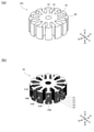
- FIG. 1 is a plan view showing a magnetic core according to an embodiment of the present invention
- FIG. 1 is a diagram showing a core assembly provided in FIG. 1 (a).
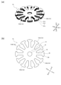
- A) is a diagram showing a block strip included in the core assembly shown in FIG. 1 (b), and (b) is a plan view of the block strip.
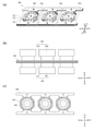
- A) An example of a fixing portion provided on the block strip, a diagram showing a case where the thin strip laminate is cut and welded at the same time (fusing), and (b) provided on the block strip. It is another example of the fixed portion, and is the figure which shows the case where a part of the cut surface of the laminated body of a thin band is welded.
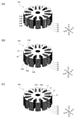
- FIG. 1 A diagram showing one of the modified examples of the core assembly included in the magnetic core according to the embodiment of the present invention, (b) Other modified examples of the core assembly included in the magnetic core according to the embodiment of the present invention. It is a figure showing one, and (c) the figure which shows another one of the modification of the core assembly provided in the magnetic core which concerns on one Embodiment of this invention. It is a flowchart which shows an example of the manufacturing method of the magnetic core which concerns on one Embodiment of this invention. It is a flowchart which shows the other example of the manufacturing method of the magnetic core which concerns on one Embodiment of this invention. It is a flowchart which shows another example of the manufacturing method of the magnetic core which concerns on one Embodiment of this invention.
- FIG. 9 It is a figure and is a figure which shows the arrangement of the heat treatment apparatus in the heat treatment of FIG. 9 (b).
- A It is a figure explaining the modification of the heat treatment of the coupled laminate of FIG. 9 (b), and (b) is a plan view which shows the shape of the heat reservoir used for the heat treatment of FIG. 10 (a).
- A) is a plan view showing an example of a block strip manufactured by the manufacturing method shown in the flowchart of FIG. 7, and (b) is a diagram illustrating a fixed portion of the block strip of FIG. 10 (a).
- FIG. 14 A plan view showing the shape of an amorphous ribbon for forming a core assembly included in the magnetic core according to another embodiment of the present invention, and (b) formed from the amorphous ribbon of FIG. 12 (a). It is a figure which shows the shape of the block thin band.
- (A) is a diagram showing a core assembly having a block strip of FIG. 12 (b), and (b) is a diagram showing a core assembly obtained by further combining the core assemblies of FIG. 13 (a).
- FIG. 1A is a plan view showing a magnetic core according to an embodiment (first embodiment) of the present invention.
- FIG. 1 (b) is a diagram showing a core assembly included in FIG. 1 (a).
- FIG. 2 (a) is a diagram showing a block strip included in the core assembly shown in FIG. 1 (b).
- FIG. 2B is a plan view of the block strip.
- the magnetic core 100 has the shape of a motor stator. Specifically, the magnetic core 100 has a cylindrical main body 10 having a through hole 20 passing through a central axis along the Z1-Z2 direction, and a radial (inward direction in the XY plane) from the outer surface of the cylindrical main body 10. It has a plurality of extending teeth 30 and.
- the magnetic core 100 shown in FIG. 1 has 12 teeth 30, and a tip portion 40 having a protruding portion protruding in the circumferential direction is located at the outer end portion of each tooth 30.
- the magnetic core 100 is a core assembly 50 made of a soft magnetic material shown in FIG. 1 (b) coated with an impregnation coat.
- the impregnation coat is formed by adhering a coating material made of a resin-based material to the surface of the core assembly 50 and impregnating it.
- the coating material is made of, for example, an epoxy resin.
- the thickness of the impregnated coat is set so that the magnetic core 100 appropriately covers the core assembly 50, which is a conductor, and has appropriate insulating properties. By way of example without limitation, the thickness of the impregnated coat is 0.1 ⁇ m to 5 ⁇ m.
- the core assembly 50 is composed of a plurality of block strips 51.
- the core assembly 50 shown in FIG. 1 (b) consists of a stack of five block strips 51, 52, 53, 54, 55 in the Z1-Z2 direction.
- the block strip 51 is a laminate of a plurality of nanocrystal strips 511.
- the nanocrystal strip 511 is made of a nanocrystal-containing alloy material.
- the block strip 51 shown in FIG. 2A includes a laminate of n nanocrystal strips 511 in the Z1-Z2 direction.
- the shape of the block strip 51 in a plan view is the same as that of the magnetic core 100, and penetrates through the center of the circular main body 11. Twelve teeth 31 radially extend from the outer surface of the main body portion 11 and have a portion 21, and a tip portion 41 having a protruding portion protruding in the circumferential direction is located at the outer end portion of each tooth 31.
- the block strip 51 has a fixing portion 51B in which adjacent nanocrystal strips are fixed to each other in the stacking direction (Z1-Z2 direction).
- the fixing portion 51B is provided on a part of the tip portions 41 of the four teeth 31.
- the fixing portion 51B is composed of a laser welded portion.
- the core assembly 50 shown in FIG. 1B is manufactured by arranging a plurality of block strips 51 prepared as an integral body of the plurality of nanocrystal strips 511.
- the block strip 51 problems such as breakage are less likely to occur in the nanocrystal strips as compared with the case where the nanocrystal strips are laminated one by one to form a laminated core, and as a result, the core assembly 50 is impregnated. It is possible to improve the quality of the magnetic core 100 which is a coated body.
- the size of the entire core assembly 50 can be easily adjusted by changing the number of arrangements of the block strips 51, which are easy to handle, and specifically by changing the number of layers. Therefore, it is possible to easily manufacture the magnetic core 100 having different magnetic characteristics. Further, since the magnetic characteristics of the magnetic core 100 can be changed only by changing the number of layers of the core assembly 50, the magnetic characteristics of the magnetic core 100 can be changed without changing the heat treatment conditions of the amorphous thin band laminate. .. As described above, if the number of layers of the amorphous ribbon is changed, it is necessary to newly set the heat treatment conditions. Therefore, the magnetic core 100 according to the present embodiment is compared with the magnetic core manufactured by such a method. Has excellent quality stability and productivity.
- the fixing portion 51B of the block strip 51 is a laser welded portion, the adjacent nanocrystal strips 511 and 511 are electrically connected through the fixing portion 51B. Therefore, when an eddy current flows through the magnetic core 100, the short-circuit path of the eddy current is in units of 51 block strips. That is, since the core assembly 50 of the magnetic core 100 has a structure in which a plurality of block strips 51 are arranged, the short-circuit path is a block strip 51 unit. Therefore, it is possible to relatively reduce the eddy current loss generated in the magnetic core 100.
- the fixing method of the fixing portion 51B is not limited. Adjacent nanocrystal strips in the block strip 51 may be fixed by an adhesive.
- the fixing portion 51B When the fixing portion 51B is located so as to include the side surface of the nanocrystal thin band 511, the fixing portion 51B may be a cut portion of the nanocrystal thin band 511.
- FIG. 3A is an example of the fixing portion 51B provided on the block strip 51, in which the laminated body of the nanocrystal strip 511 was cut (cut mark 51C) and welded (fixed portion 51B) at the same time. It is a figure which shows the case (fusing).
- FIG. 3B is another example of the fixing portion 51B provided on the block strip 51, in which a part of the cut surface of the laminated body of the nanocrystal strip 511 is welded to form the fixing portion 51B. It is a figure which shows.
- the five block strips 51, 52, 53, 54, 55 arranged along the first direction (Z1-Z2 direction) are the fixing portions 51B, 52B, respectively.
- 53B, 54B, 55B have a shift-arranged block ribbon group having a portion not aligned in the first direction (Z1-Z2 direction).
- the block strip 51 has four anchors 51B, all of which are located on the protrusions 42 of the tip 41 of the teeth 31 and the block 51.
- the fixing portions 51B are arranged every other in the twelve teeth 31 possessed by the above.
- the two adjacent block strips do not have the two fixing portions 51B and 52B lined up in the first direction (Z1-Z2 direction).
- the fixing portions 51B, 52B, 53B, 54B, 55B have different magnetic properties from other portions. Even so, it is expected that spatial variation in the magnetic properties of the core assembly 50 will be less likely to occur.
- FIG. 4 is a diagram showing one of the modified examples of the core assembly included in the magnetic core according to the embodiment of the present invention.
- the fixing portions of the adjacent block strips may be arranged in the first direction (Z1-Z2 direction). Again, because there is magnetic continuity but no electrical continuity between the two adjacent block strips, the short circuit path of the core assembly 501 is the block strips 51, 52, 53, 54, 55, respectively. It becomes a unit of.
- the fixing portion is not provided on the outermost surface of the core assembly 502, and the side surface located inside the outermost surface is provided.
- a fixing portion is provided.
- the fixing portions 51B, 53B, 54B, 55B are provided on one side surface of the circumferential protrusion 42 at the tip portion 41 of the teeth 31.
- a magnetic path may be set so as to penetrate the outermost surface of the core assembly 502.
- the passage of the magnetic path through the fixed portion may affect the characteristics of the magnetic component (for example, the rotational characteristics of the motor). be. Since the core assembly 502 is not provided with a fixing portion on the outer side surface of the protrusion 42 corresponding to the outermost surface, it is expected that the magnetic characteristics of the magnetic core 100 provided with the core assembly 502 will be less affected by the fixing portion. Ru.
- the core assembly 503 shown in FIG. 4C is a main body 11 located in a space (corresponding to a part of the slot SL of the magnetic core 100) between two adjacent teeth 31 in the block strip 51.
- a fixing portion 51B is provided on the outer side surface. When the fixing portion 51B is provided at this position, the influence of the generation of the fixing portion 51B on the block thin band 51 can be reduced as compared with the case where the fixing portion 51B is provided on a part of the teeth 31.
- the teeth 31 may be partially deformed (solidified after melting) due to the heat given by the laser welding, but the core In the case of the assembly 503, even if deformation occurs when the fixing portion 51B is formed by laser welding, since the fixing portion 51B is provided in the main body portion 11, the magnetic characteristics of the magnetic core 100 by the fixing portion 51B can be obtained.
- the influence of the above can be smaller than that in the case where the fixing portion 51B is formed on a part of the teeth 31.
- the nanocrystal strip 511 is a strip made of a nanocrystal-containing alloy material obtained by nanocrystallizing an amorphous strip made of an amorphous alloy material by heat treatment.
- the nanocrystals contained in the nanocrystal ribbon have the bcc-Fe phase as the main phase.
- the plurality of nanocrystal strips 511 constituting the block strip 51 can be obtained by temporarily heat-treating a laminate of amorphous strips corresponding to the block strip 51.
- the thickness of the block strip 51 is set to a thickness capable of forming the nanocrystal strip 511 from the amorphous strip by this heat treatment.
- the layered body of the amorphous thin band becomes thick, the heat generated when the amorphous thin band crystallizes is less likely to be released to the outside of the laminated body, and the controllability of the heat treatment is lowered. Therefore, from the viewpoint of appropriately advancing the heat treatment, it is preferable to set an upper limit on the thickness of the block strip 51.
- the nanocrystal ribbon 511 produced by the heat treatment is hard and brittle, it is preferable that a certain number of nanocrystal ribbons 511 are laminated in the laminate produced by the heat treatment from the viewpoint of improving the handleability. From this viewpoint, it is preferable to set the lower limit of the thickness of the block strip 51.
- the thickness of the block strip 51 is preferably 3 mm or less, and may be preferably 2 mm or less. Further, the thickness of the block strip 51 may be preferably 200 ⁇ m or more, and more preferably 500 ⁇ m or more.
- FIG. 5 is a flowchart showing an example of a method for manufacturing a magnetic core according to an embodiment (first embodiment) of the present invention.
- an amorphous ribbon is manufactured by a single roll method or the like (step S101).
- the obtained amorphous strip is cut to an appropriate length, and the obtained strip is punched to obtain the shape shown in FIG. 2 in a plan view (shape seen from the Z1-Z2 direction).
- a punching member to have is obtained (step S102).
- a plurality of the obtained punched members are laminated to obtain a laminated body (step S103).
- the amorphous ribbon has toughness more than the nanocrystal strip after heat treatment, chipping of the strip is less likely to occur even if the laminating work is performed.
- a block body is obtained by performing a block formation step of laser welding the outer surface of the obtained laminated body at a plurality of places (step S104).
- the obtained block body is heat-treated to obtain a block strip 51 (step S105).
- the conditions of the heat treatment are that crystallization proceeds appropriately in all of the amorphous strips constituting the block body, and defects caused by the heat generated by the crystallization (generation of unnecessary substances such as compounds, burning, etc.) ) Is set to be appropriately suppressed.
- a plurality of block strips 51 obtained by heat treatment are laminated to obtain the core assembly 50 shown in FIG. 1 (b).
- the blocking portion 21 penetrates the block strip 52 adjacent to the block strip 51 so that the adjacent fixing portions (for example, the fixing portion 51B and the fixing portion 52B) do not line up in the first direction (Z1-Z2 direction).
- Rotational laminating is performed by rotating and laminating around the central axis of the above (step S106).
- the magnetic core 100 is obtained by performing a secondary heat treatment (step S107) on the core assembly 50 as necessary and then performing an impregnation coating (step S108). After the impregnation coating is applied, shape adjustment such as deburring may be performed as necessary (step S109).
- FIG. 6 is a flowchart showing another example of the method for manufacturing a magnetic core according to an embodiment of the present invention.
- FIG. 8A is an explanatory diagram of a process for manufacturing a hoop material made of an amorphous ribbon for forming a nanocrystal ribbon included in the magnetic core according to the embodiment of the present invention.
- FIG. 8B is an explanatory diagram of the configuration of a hoop material made of an amorphous ribbon manufactured by the manufacturing process of FIG. 8A.
- FIG. 8 (c) is a diagram illustrating a punched portion of a hoop material made of an amorphous ribbon shown in FIG. 8 (b).
- FIG. 9A is a diagram showing a coupled laminate obtained by subdividing a hoop material made of an amorphous ribbon shown in FIG. 8B.
- FIG. 9B is a diagram illustrating the heat treatment of the coupled laminate of FIG. 9A.
- FIG. 9 (c) is a diagram showing the arrangement of the heat treatment apparatus in the heat treatment of FIG. 9 (b).
- an amorphous strip is first manufactured by a single roll method or the like in the same manner as in the manufacturing method shown in the flowchart of FIG. 5 (step S201). Since the obtained amorphous ribbon has higher toughness than the nanocrystal strip, the obtained amorphous strip is wound into a roll (amorphous roll 201).
- FIG. 8A shows a method for manufacturing the roll-to-roll hoop material 205.
- the amorphous strip 202 is fed out from the amorphous roll 201 in one direction (specifically, the X1-X2 direction X1 side), and the amorphous strip 202 is punched by a punching die (upper die 203, lower die 204). conduct.
- the obtained hoop material 205 has a core strip portion 300 which is finally a direct component of the magnetic core 100 and an in-plane direction of the core strip portion 300 ( Specifically, the punching portion 350 including the base material portion 211 extending in the X1-X2 direction and the connecting rail 212 connecting the core strip portion 300 and the base material portion 211 extends in the direction in which the base material portion 211 extends (specifically, in the X1-X2 direction). They are arranged side by side in the X1-X2 direction).
- the base material portion 211 is provided with a hole for positioning (positioning portion 213).
- the shape of the core strip portion 300 of the punching portion 350 in a plan view is similar to that of the block strip 51, and is circular.
- a penetrating portion 320 is provided at the center of the main body portion 310, twelve teeth 330 extend radially from the outer surface, and a tip portion 340 having a protruding portion 341 protruding in the circumferential direction is provided at the outer end portion of each tooth 330.
- some of the connecting bars 212 project in the circumferential direction (Y1-Y2 direction) at the tip portions 340 of the two teeth 330 extending along the X1-X2 direction.
- the other part of the connecting rail 212 is provided so as to connect to the protruding portion 341 protruding in the circumferential direction (X1-X2 direction) at the tip portion 340 of the two teeth 330 extending along the Y1-Y2 direction. ing. Therefore, the cut portion CP of the connecting rail 212 is not positioned so as to be connected to the outermost surface of the tip portion 340. Therefore, as shown in FIG. 4B, the block strip 51 obtained from the punching portion 350 shown in FIG. 8C is fixed to the outermost surface of the core strip 51B after cutting. That is, the cutting mark 51C) is not located.
- the crystal state of the cutting mark 51C may change from that of other parts regardless of whether the cutting method is laser or mechanical cutting. Therefore, the magnetic core 100 may have different magnetic characteristics from other parts in the portion where the cutting mark 51C is located. Therefore, when the magnetic path of the magnetic circuit of the magnetic component including the magnetic core 100 passes through the cutting mark 51C, the magnetic characteristics change in that portion, and as a result, the stability of the magnetic characteristics of the magnetic component is affected. May reach. It is possible to minimize these effects by optimizing the cutting method.
- a magnetic path may pass through the outermost surface thereof. For example, the punching portion 350 shown in FIG. 10 (a). Since the core assembly 502 shown in FIG. 4B is obtained, the possibility that the magnetic path of the magnetic circuit of the magnetic component passes through the cutting mark 51C can be further reduced.
- the hoop material 205 obtained by punching is wound up into a roll material 206.
- the hoop material 205 is fed out from the roll material 206 and cut into small pieces to obtain a coupled member 251 to which a predetermined number (for example, 3) of punching parts 350 are connected (step S203).
- a predetermined number for example, 3
- a plurality of the obtained coupled members 251 are laminated in the Z1-Z2 direction to obtain a coupled laminated body 360 (step S204).
- a plurality of coupled members 251 can be easily laminated in the Z1-Z2 direction without touching the core thin band portion 300.
- the obtained coupled laminated body 360 is heat-treated (step S205).
- a plurality of sets of heat treatment devices 395, 396 are set according to the number of laminated bodies of the core strip portion 300 included in the coupled member 251 of the coupled laminated body 360. Is prepared, and the laminated body of the core thin band portion 300 is sandwiched between the heat treatment devices 395 and 396 of each set from the laminating direction (Z1-Z2 direction) of the coupled laminated body 360.
- the heat treatment apparatus 395 and 396 are for controlling the temperature of the core zonal portion 300, and have a substantially columnar shape, respectively, and heat reservoirs 370 and 371 that are in direct contact with the core zonal portion 300. It is provided with heater blocks 390 and 391 for heating the heat reservoirs 370 and 371. As a result, the heat treatment apparatus 395 and 396 have a function of applying heat to the core thin band portion 300 and a function of receiving heat from the core thin band portion 300. By arranging a plurality of a set of heat treatment devices 395 and 396 in this way, it is possible to make the conditions of the heat treatment applied to each of the laminated bodies of the plurality of core strips 300 of the coupled laminated body 360 equal.
- the heat treatment conditions are such that crystallization proceeds appropriately in all the amorphous strips constituting the core strip portion 300 of the coupled laminate 360, and defects (unnecessary substances such as compounds) caused by the heat generated by the crystallization occur. (Generation, burning, etc.) are set to be appropriately suppressed.
- the amorphous ribbon constituting the core strip portion 300 of the coupled laminate 360 is crystallized into a nanocrystal strip 511.
- the connecting portion (cutting portion CP) with the connecting rail 212 in the protruding portion 341 is laser-fused to separate the laminated body of the core thin band portion 300 (nanocrystal thin band 511), and this laminated body is formed.
- a plurality of nanocrystal strips 511 are fixed to obtain the block strips 51 shown in FIG. 4 (b) (step S206). Therefore, the fixing portion 51B of the block strip 51 manufactured by the manufacturing method shown in the flowchart of FIG. 6 is also a cutting mark 51C.
- step S207 rotational lamination
- step S208 a secondary heat treatment
- step S208 an impregnation coating
- step S210 shape adjustment
- FIG. 10 (a) is a diagram illustrating a modified example of the heat treatment of the coupled laminate of FIG. 9 (b), and FIG. 11 (b) shows the shape of the heating member used for the heat treatment of FIG. 10 (a). It is a plan view which represents.
- the cut portion CP when the heat reservoirs 370 and 371 provided in the heat treatment apparatus 395 and 396 have a substantially cylindrical shape, as shown in FIG. 9 (c), the cut portion CP. (See FIG. 8 (c)) is in direct contact with the heat reservoir 370. Therefore, in the coupled laminate 360 after the heat treatment step (step S205), the cut portion CP is also heat-treated and crystallized. Therefore, the cutting portion CP may have a reduced cutting workability. As described above, the protruding portion 341 to which the cutting portion CP is connected is unlikely to pass a magnetic path, but if the cutting workability is lowered, the shape uniformity of the cutting mark 51C is lowered and the block is thin. It may affect the maintenance of the shape quality of the band 51.
- the heat treatment step if the plan view shape of the heat reservoirs 370A and 371A (shape seen from the Z1-Z2 direction) corresponds to the plan view shape of the core lamellae portion 300, the heat treatment step.
- step S205 the portion of the connecting rail 212 connected to the protruding portion 341 of the tip portion 340 is not heat-treated and remains an amorphous alloy. Therefore, the coupled laminated body 360 after the heat treatment has good cutting workability of the cutting portion CP, and as shown in FIG. 4B, the side surface of the protruding portion 341 of the tip portion 340 of the block strip 51. Even if the fixing portion 51B is positioned in the position, the shape quality is unlikely to deteriorate.
- FIG. 7 is a flowchart showing another example of the method for manufacturing a magnetic core according to an embodiment of the present invention.
- the “separate cutting / blocking” step of step S206 is divided into a separation cutting step (step S206A) and a blocking step (step S206B) in comparison with the flowchart shown in FIG. It differs in that it is done.
- the separation cutting step is performed by, for example, mechanical cutting
- the blocking step is performed by, for example, laser welding.
- the heat treatment step (step S205) is performed after the blocking step (step S206B) in comparison with the flowchart shown in FIG. When the portion made of an amorphous alloy undergoes the heat treatment step (step S205), it is nanocrystallized and the cutting processability is lowered.
- step S206A the separation cutting step
- step S206B the blocking step
- FIG. 11A is a plan view showing an example of a block strip manufactured by the manufacturing method shown in the flowchart of FIG. 7.
- FIG. 11B is a diagram illustrating a fixed portion of the block strip of FIG. 11A.
- the block strip 510 shown in FIG. 11 has a cut balance 214 at the outer end of the tip 41 of the teeth 31.
- the cutting residue 214 is the cutting residue when the cutting portion CP of the connecting rail 212 is cut in the separation cutting step (step S206A).
- the fixing portion 51B is laser-welded to the outer surface of the main body portion 11 forming the space corresponding to the slot SL, similarly to the core assembly 503 shown in FIG. 4 (c). It is provided by.
- FIG. 12 (a) is a plan view showing the shape of an amorphous strip for forming a core assembly included in the magnetic core according to another embodiment (second embodiment) of the present invention.
- FIG. 12 (b) is a diagram showing the shape of the block strip formed from the amorphous strip of FIG. 12 (a).
- 13 (a) is a diagram showing a core assembly with the block strip of FIG. 12 (b).
- FIG. 13 (b) is a diagram showing a core assembly obtained by further combining the core assemblies of FIG. 13 (a).
- the block strips 70 are arranged side by side in directions other than the stacking direction (Z1-Z2 direction) of the nanocrystal strips 60 constituting the block strips 70. There is.
- the nanocrystal ribbon 60 has a main body portion 61 having a shape in which the annulus is divided into four halves, and the main body portion 61 in the circumferential direction of the annulus. It is provided with a convex portion 62 protruding toward the surface, a concave portion 63 recessed in the circumferential direction of the annulus in the main body 61, and a tooth 64 projecting from the inner peripheral side of the annulus to the center side of the annulus.
- the convex portion 62 and the concave portion 63 have a shape that allows them to be fitted so that they can be connected to another nanocrystal ribbon 60.
- the block strip 70 having the fixing portion 70B can be obtained.
- the block strip 70 has a fitting protrusion 71 based on the convex portion 62 of the nanocrystal strip 60 and a fitting recess based on the recess 63 of the nanocrystal strip 60 so that the block strip 70 can be fitted with another block strip 70.
- 72 With 72.
- the core assembly 90 has a ring assembly 80 in which four block strips 70 are fitted in the fitting portion 80C and the entire shape is annular.
- the arrangement direction of the block strips 70 in the ring assembly 80 is different from the stacking direction (Z1-Z2 direction) of the nanocrystal strips 60.
- a plurality of ring assemblies three ring assemblies 81, 82, 83 in FIG. 13 (b) are laminated to form the core assembly 90.
- the fixing portions 81B, 82B, and 83B of the core assembly 90 derived from the fixing portion 70B of the block strip 70 are arranged in the stacking direction (Z1-Z2 direction), but the core assembly 90 is electrically operated for each block strip 70.
- the short circuit path is limited to the block strip 70 because it is separated into. Therefore, the magnetic core provided with the core assembly 90 is unlikely to have a large eddy current loss.
- FIG. 14A is an external view of a motor which is an example of a magnetic product in which a magnetic component provided with a magnetic core according to an embodiment of the present invention is used.
- 14 (b) is an external view of a rotor which is one of the magnetic parts included in the motor of FIG. 14 (a).
- 14 (c) is an external view of a stator which is another magnetic component included in the motor of FIG. 14 (a).
- a rotation shaft 702 passing through the center of the bottom surface of the motor body 701 having a cylindrical shape protrudes to the Z1 side in the Z1-Z2 direction.
- the rotor 710 shown in FIG. 14B is rotatably arranged around the rotation axis in the Z1-Z2 direction.
- the rotor 710 is fixed to a rotor main body 711 having a hollow cylindrical shape in which one of the bottom surfaces (Z1-Z2 direction Z1 side) is open and a central portion of the bottom surface of the other (Z1-Z2 direction Z2 side) of the rotor main body 711. It is provided with a rotating shaft 702.
- a plurality of magnets 712 are arranged side by side in the circumferential direction on the inner wall surface of the rotor main body 711.
- a stator 720 having a columnar outer shape is arranged between the rotor main body 711 of the rotor 710 and the rotating shaft 702.
- the stator 720 includes a magnetic core 100 according to an embodiment of the present invention, and a coil 721 wound around each of the plurality of teeth 30 thereof.
- a rotation shaft 702 is inserted through the through hole 20 of the magnetic core 100.
- the magnet 712 of the rotor 710 is provided on the inner side wall of the rotor main body 711 so as to face each of the tip portions 40 of the teeth 30 of the magnetic core 100.
Landscapes
- Engineering & Computer Science (AREA)
- Power Engineering (AREA)
- Chemical & Material Sciences (AREA)
- Crystallography & Structural Chemistry (AREA)
- Inorganic Chemistry (AREA)
- Materials Engineering (AREA)
- Physics & Mathematics (AREA)
- Electromagnetism (AREA)
- Dispersion Chemistry (AREA)
- Manufacturing & Machinery (AREA)
- Manufacturing Cores, Coils, And Magnets (AREA)
Priority Applications (4)
| Application Number | Priority Date | Filing Date | Title |
|---|---|---|---|
| JP2022547559A JPWO2022054722A1 (https=) | 2020-09-09 | 2021-09-03 | |
| EP21866681.6A EP4191617A4 (en) | 2020-09-09 | 2021-09-03 | MAGNETIC CORE AND MAGNETIC COMPONENT |
| CN202180049331.2A CN115843384A (zh) | 2020-09-09 | 2021-09-03 | 磁芯及磁性部件 |
| US18/172,542 US20230207179A1 (en) | 2020-09-09 | 2023-02-22 | Magnetic core and magnetic component |
Applications Claiming Priority (2)
| Application Number | Priority Date | Filing Date | Title |
|---|---|---|---|
| JP2020-151207 | 2020-09-09 | ||
| JP2020151207 | 2020-09-09 |
Related Child Applications (1)
| Application Number | Title | Priority Date | Filing Date |
|---|---|---|---|
| US18/172,542 Continuation US20230207179A1 (en) | 2020-09-09 | 2023-02-22 | Magnetic core and magnetic component |
Publications (1)
| Publication Number | Publication Date |
|---|---|
| WO2022054722A1 true WO2022054722A1 (ja) | 2022-03-17 |
Family
ID=80815901
Family Applications (1)
| Application Number | Title | Priority Date | Filing Date |
|---|---|---|---|
| PCT/JP2021/032510 Ceased WO2022054722A1 (ja) | 2020-09-09 | 2021-09-03 | 磁性コアおよび磁気部品 |
Country Status (5)
| Country | Link |
|---|---|
| US (1) | US20230207179A1 (https=) |
| EP (1) | EP4191617A4 (https=) |
| JP (1) | JPWO2022054722A1 (https=) |
| CN (1) | CN115843384A (https=) |
| WO (1) | WO2022054722A1 (https=) |
Cited By (2)
| Publication number | Priority date | Publication date | Assignee | Title |
|---|---|---|---|---|
| CN115036125A (zh) * | 2022-06-27 | 2022-09-09 | 中国科学院空间应用工程与技术中心 | 一种纳米晶磁芯及其制备方法和磁性设备 |
| JP2022162506A (ja) * | 2021-04-12 | 2022-10-24 | 株式会社東北マグネットインスティテュート | 金属薄片及び積層コアの製造装置、製造方法、並びに熱処理装置 |
Families Citing this family (1)
| Publication number | Priority date | Publication date | Assignee | Title |
|---|---|---|---|---|
| WO2022054725A1 (ja) * | 2020-09-09 | 2022-03-17 | アルプスアルパイン株式会社 | 磁性コアおよび磁気部品 |
Citations (5)
| Publication number | Priority date | Publication date | Assignee | Title |
|---|---|---|---|---|
| WO1999021264A1 (en) | 1997-10-17 | 1999-04-29 | Seiko Epson Corporation | Motor laminated core, method of manufacturing same, motor and ink jet recording device |
| JP2007159300A (ja) * | 2005-12-07 | 2007-06-21 | Toyota Motor Corp | 回転電機の固定子 |
| JP2017108578A (ja) * | 2015-12-11 | 2017-06-15 | 株式会社三井ハイテック | 固定子積層鉄心及びその製造方法 |
| JP2017141508A (ja) | 2016-02-09 | 2017-08-17 | 国立大学法人東北大学 | アモルファス合金薄帯の積層体の熱処理装置および軟磁性コア |
| WO2018105473A1 (ja) * | 2016-12-07 | 2018-06-14 | パナソニック株式会社 | 鉄心及びモータ |
Family Cites Families (9)
| Publication number | Priority date | Publication date | Assignee | Title |
|---|---|---|---|---|
| JP4867978B2 (ja) * | 2008-11-14 | 2012-02-01 | 株式会社デンソー | モータおよびその制御装置 |
| US9287028B2 (en) * | 2009-08-24 | 2016-03-15 | Nec Tokin Corporation | Alloy composition, Fe-based nano-crystalline alloy and forming method of the same |
| WO2017090137A1 (ja) * | 2015-11-25 | 2017-06-01 | 三菱電機株式会社 | 回転電機および回転電機の製造方法 |
| CN106026425B (zh) * | 2016-01-07 | 2019-05-14 | 安泰科技股份有限公司 | 具有纳米晶合金铁心的开关磁阻电机及制备方法 |
| CN108231316B (zh) * | 2016-12-14 | 2024-08-16 | 上海威斯科电子材料有限公司 | 一种非晶纳米晶模块化叠合片、磁元件及其制备方法 |
| US11225049B2 (en) * | 2017-02-24 | 2022-01-18 | Panasonic Corporation | Laminated member, laminated body, and motor |
| EP3683930A4 (en) * | 2017-09-11 | 2020-12-02 | Panasonic Intellectual Property Management Co., Ltd. | IRON CORE AND MOTOR USING LEDIT IRON CORE |
| JP6802202B2 (ja) * | 2018-02-22 | 2020-12-16 | トヨタ自動車株式会社 | 軟磁性薄帯の積層体 |
| JP7028122B2 (ja) * | 2018-09-21 | 2022-03-02 | トヨタ自動車株式会社 | 積層コアの製造方法 |
-
2021
- 2021-09-03 JP JP2022547559A patent/JPWO2022054722A1/ja active Pending
- 2021-09-03 EP EP21866681.6A patent/EP4191617A4/en not_active Withdrawn
- 2021-09-03 WO PCT/JP2021/032510 patent/WO2022054722A1/ja not_active Ceased
- 2021-09-03 CN CN202180049331.2A patent/CN115843384A/zh active Pending
-
2023
- 2023-02-22 US US18/172,542 patent/US20230207179A1/en active Pending
Patent Citations (5)
| Publication number | Priority date | Publication date | Assignee | Title |
|---|---|---|---|---|
| WO1999021264A1 (en) | 1997-10-17 | 1999-04-29 | Seiko Epson Corporation | Motor laminated core, method of manufacturing same, motor and ink jet recording device |
| JP2007159300A (ja) * | 2005-12-07 | 2007-06-21 | Toyota Motor Corp | 回転電機の固定子 |
| JP2017108578A (ja) * | 2015-12-11 | 2017-06-15 | 株式会社三井ハイテック | 固定子積層鉄心及びその製造方法 |
| JP2017141508A (ja) | 2016-02-09 | 2017-08-17 | 国立大学法人東北大学 | アモルファス合金薄帯の積層体の熱処理装置および軟磁性コア |
| WO2018105473A1 (ja) * | 2016-12-07 | 2018-06-14 | パナソニック株式会社 | 鉄心及びモータ |
Non-Patent Citations (1)
| Title |
|---|
| See also references of EP4191617A4 |
Cited By (3)
| Publication number | Priority date | Publication date | Assignee | Title |
|---|---|---|---|---|
| JP2022162506A (ja) * | 2021-04-12 | 2022-10-24 | 株式会社東北マグネットインスティテュート | 金属薄片及び積層コアの製造装置、製造方法、並びに熱処理装置 |
| JP7694154B2 (ja) | 2021-04-12 | 2025-06-18 | 株式会社アイシン | 金属薄片及び積層コアの製造装置並びに製造方法 |
| CN115036125A (zh) * | 2022-06-27 | 2022-09-09 | 中国科学院空间应用工程与技术中心 | 一种纳米晶磁芯及其制备方法和磁性设备 |
Also Published As
| Publication number | Publication date |
|---|---|
| US20230207179A1 (en) | 2023-06-29 |
| CN115843384A (zh) | 2023-03-24 |
| JPWO2022054722A1 (https=) | 2022-03-17 |
| EP4191617A4 (en) | 2024-08-14 |
| EP4191617A1 (en) | 2023-06-07 |
Similar Documents
| Publication | Publication Date | Title |
|---|---|---|
| WO2022054722A1 (ja) | 磁性コアおよび磁気部品 | |
| CN102737804B (zh) | 电磁部件及其制造方法 | |
| US12445000B2 (en) | Magnetic core and magnetic component | |
| JP2014079068A (ja) | ロータコア及びその製造方法 | |
| JP6294471B2 (ja) | アキシャルエアギャップ型回転電機及び回転電機用ボビン | |
| EP2600508B1 (en) | Rotor for motor and method of manufacturing the same | |
| JP6522252B2 (ja) | 薄帯部品とその製造方法、および、薄帯部品を用いたモータ | |
| JP2011067027A (ja) | 鋼板対、積層鋼板、及び回転電機コアの製造方法 | |
| JP2013115965A (ja) | 回転機用ステータの製造方法および回転機用ステータ | |
| WO2019065827A1 (ja) | ラジアルギャップ型回転電機及びその製造方法、回転電機用ティース片の製造装置、回転電機用ティース部材の製造方法 | |
| JP2014093803A (ja) | 回転機用ロータおよび回転機用ロータの製造方法 | |
| CN108496293B (zh) | 具有印刷的连接片的电工钢片 | |
| CN103026435A (zh) | 电抗器装置 | |
| US20230208213A1 (en) | Magnetic core, hoop material, and magnetic component | |
| JP6395028B2 (ja) | 回転電機用コアの製造方法 | |
| JP6207769B1 (ja) | 固定子、電動機、固定子の製造方法および電動機の製造方法 | |
| JP2008270269A (ja) | 巻線型電子部品用コア、その製造方法及び巻線型電子部品 | |
| JP5306975B2 (ja) | 積層構造体及びその製造方法 | |
| JP2002075747A (ja) | ギャップ付磁芯およびその製造方法 | |
| JP2009207290A (ja) | 回転電機用コイルの製造方法 | |
| JP2013017292A (ja) | ロータコア及びその製造方法 | |
| WO2024116811A1 (ja) | 非晶質合金片の製造方法、積層鉄心の製造方法及び積層鉄心 | |
| WO2022172938A1 (ja) | モータのコアブロック及びモータのコアブロックの製造方法 | |
| WO2011033646A1 (ja) | 鋼板対、積層鋼板及び回転電機コア | |
| JP6164093B2 (ja) | 永久磁石の製造方法 |
Legal Events
| Date | Code | Title | Description |
|---|---|---|---|
| 121 | Ep: the epo has been informed by wipo that ep was designated in this application |
Ref document number: 21866681 Country of ref document: EP Kind code of ref document: A1 |
|
| ENP | Entry into the national phase |
Ref document number: 2022547559 Country of ref document: JP Kind code of ref document: A |
|
| ENP | Entry into the national phase |
Ref document number: 2021866681 Country of ref document: EP Effective date: 20230227 |
|
| NENP | Non-entry into the national phase |
Ref country code: DE |
|
| WWW | Wipo information: withdrawn in national office |
Ref document number: 2021866681 Country of ref document: EP |