WO2022054722A1 - Magnetic core and magnetic component - Google Patents
Magnetic core and magnetic component Download PDFInfo
- Publication number
- WO2022054722A1 WO2022054722A1 PCT/JP2021/032510 JP2021032510W WO2022054722A1 WO 2022054722 A1 WO2022054722 A1 WO 2022054722A1 JP 2021032510 W JP2021032510 W JP 2021032510W WO 2022054722 A1 WO2022054722 A1 WO 2022054722A1
- Authority
- WO
- WIPO (PCT)
- Prior art keywords
- nanocrystal
- block
- magnetic core
- magnetic
- strip
- Prior art date
Links
Images


Classifications
-
- H—ELECTRICITY
- H01—ELECTRIC ELEMENTS
- H01F—MAGNETS; INDUCTANCES; TRANSFORMERS; SELECTION OF MATERIALS FOR THEIR MAGNETIC PROPERTIES
- H01F27/00—Details of transformers or inductances, in general
- H01F27/24—Magnetic cores
- H01F27/25—Magnetic cores made from strips or ribbons
-
- H—ELECTRICITY
- H02—GENERATION; CONVERSION OR DISTRIBUTION OF ELECTRIC POWER
- H02K—DYNAMO-ELECTRIC MACHINES
- H02K1/00—Details of the magnetic circuit
- H02K1/02—Details of the magnetic circuit characterised by the magnetic material
-
- H—ELECTRICITY
- H01—ELECTRIC ELEMENTS
- H01F—MAGNETS; INDUCTANCES; TRANSFORMERS; SELECTION OF MATERIALS FOR THEIR MAGNETIC PROPERTIES
- H01F1/00—Magnets or magnetic bodies characterised by the magnetic materials therefor; Selection of materials for their magnetic properties
- H01F1/01—Magnets or magnetic bodies characterised by the magnetic materials therefor; Selection of materials for their magnetic properties of inorganic materials
- H01F1/03—Magnets or magnetic bodies characterised by the magnetic materials therefor; Selection of materials for their magnetic properties of inorganic materials characterised by their coercivity
- H01F1/12—Magnets or magnetic bodies characterised by the magnetic materials therefor; Selection of materials for their magnetic properties of inorganic materials characterised by their coercivity of soft-magnetic materials
- H01F1/14—Magnets or magnetic bodies characterised by the magnetic materials therefor; Selection of materials for their magnetic properties of inorganic materials characterised by their coercivity of soft-magnetic materials metals or alloys
- H01F1/147—Alloys characterised by their composition
- H01F1/153—Amorphous metallic alloys, e.g. glassy metals
- H01F1/15333—Amorphous metallic alloys, e.g. glassy metals containing nanocrystallites, e.g. obtained by annealing
-
- H—ELECTRICITY
- H01—ELECTRIC ELEMENTS
- H01F—MAGNETS; INDUCTANCES; TRANSFORMERS; SELECTION OF MATERIALS FOR THEIR MAGNETIC PROPERTIES
- H01F3/00—Cores, Yokes, or armatures
- H01F3/02—Cores, Yokes, or armatures made from sheets
-
- H—ELECTRICITY
- H01—ELECTRIC ELEMENTS
- H01F—MAGNETS; INDUCTANCES; TRANSFORMERS; SELECTION OF MATERIALS FOR THEIR MAGNETIC PROPERTIES
- H01F41/00—Apparatus or processes specially adapted for manufacturing or assembling magnets, inductances or transformers; Apparatus or processes specially adapted for manufacturing materials characterised by their magnetic properties
- H01F41/02—Apparatus or processes specially adapted for manufacturing or assembling magnets, inductances or transformers; Apparatus or processes specially adapted for manufacturing materials characterised by their magnetic properties for manufacturing cores, coils, or magnets
- H01F41/0206—Manufacturing of magnetic cores by mechanical means
- H01F41/0213—Manufacturing of magnetic circuits made from strip(s) or ribbon(s)
- H01F41/0226—Manufacturing of magnetic circuits made from strip(s) or ribbon(s) from amorphous ribbons
-
- H—ELECTRICITY
- H02—GENERATION; CONVERSION OR DISTRIBUTION OF ELECTRIC POWER
- H02K—DYNAMO-ELECTRIC MACHINES
- H02K1/00—Details of the magnetic circuit
- H02K1/06—Details of the magnetic circuit characterised by the shape, form or construction
- H02K1/12—Stationary parts of the magnetic circuit
- H02K1/14—Stator cores with salient poles
-
- H—ELECTRICITY
- H02—GENERATION; CONVERSION OR DISTRIBUTION OF ELECTRIC POWER
- H02K—DYNAMO-ELECTRIC MACHINES
- H02K15/00—Methods or apparatus specially adapted for manufacturing, assembling, maintaining or repairing of dynamo-electric machines
- H02K15/02—Methods or apparatus specially adapted for manufacturing, assembling, maintaining or repairing of dynamo-electric machines of stator or rotor bodies
Definitions
- the present invention relates to a magnetic core and a magnetic component including such a magnetic core.
- Patent Document 1 describes a laminating jig that holds a laminated body of amorphous alloy strips, two heating plates that sandwich the laminated body from the upper and lower surfaces in the laminating direction without contacting the laminating jig, and the two heating plates.
- a heat treatment device for a laminate of amorphous alloy strips comprising a heating control device for controlling the heating temperature of the heating plate.
- Patent Document 2 a plurality of magnetic plates are laminated, and peaks and grooves are alternately formed along the rotation direction of the motor.
- a laminated core of a motor is disclosed, characterized in that a welded portion for fixing the magnetic plates to each other is provided on the surface of the grooved portion.
- the nanocrystal strip obtained by the heat treatment is fragile and difficult to handle, and the nanocrystal strip is damaged in the process of laminating the nanocrystal strip. It tends to occur, and there is a problem in terms of ensuring the quality of the magnetic core.
- An object of the present invention is to provide a magnetic core having a structure in which nanocrystal ribbons are laminated and whose magnetic characteristics are easily stabilized. It is also an object of the present invention to provide a magnetic component including such a magnetic core.
- the present invention for solving the above problems includes a magnetism having a core assembly having a structure in which a plurality of block strips composed of a plurality of laminates of nanocrystal strips made of a nanocrystal-containing alloy material are arranged.
- the core is a magnetic core characterized in that the block strips have a fixing portion in which the nanocrystal strips adjacent to each other in the stacking direction are fixed to each other.
- one nanocrystal strip can be used. Compared with the case where the laminated cores are formed by laminating them one by one, defects such as breakage are less likely to occur in the nanocrystal ribbon, and as a result, the quality of the magnetic core which is the impregnated coated body of the core assembly can be improved.
- the arrangement direction (arrangement direction) of the plurality of block zonules arranged in the core assembly constitutes the block zonules.
- the stacking direction (stacking direction) of a plurality of nanocrystal strips it has a structure in which a large number of nanocrystal strips are laminated like a conventional laminated core, but a portion integrated by a fixing portion for each predetermined number (a portion). It differs from the conventional laminated core in that it has a plurality of block strips).
- the core assembly is an assembly of a plurality of block strips
- a short-circuit path of the magnetic core including the core assembly is provided even when the fixed portion of the block strips is formed by welding, for example, and has conductivity. Is divided by the block strip.
- the obtained magnetic core is also electrically integrated, so that the short-circuit path of the magnetic core becomes long. The longer the short-circuit path, the larger the eddy current loss of the magnetic core. Therefore, the magnetic core according to the present invention, which is divided into short-circuit path block strip units, is less likely to have iron loss, particularly eddy current loss.
- the relationship between the arrangement direction of the plurality of block strips constituting the core assembly and the stacking direction of the nanocrystal strips in the block strips is arbitrary.
- the arrangement direction and the stacking direction may or may not be aligned.
- the fixing portion may include the side surface of the nanocrystal ribbon. It is easy to visually recognize the fixed portion, and it is easy to confirm the fixed state of the block thin band.
- the fixed portion may be composed of a laser welded portion. Since the nanocrystal strips are stably fixed at the anchored part, the handleability of the block strips is improved, and problems such as breakage occur during the process of arranging multiple block strips to fabricate the core assembly. Hateful.
- the nanocrystal strip may be obtained by nanocrystallizing an amorphous strip made of an amorphous alloy material by heat treatment.
- the thickness of the block strip is preferably such that the amorphous strip can generate the nanocrystal strip by the heat treatment. If the thickness of the block strip is excessively large, the temperature cannot be controlled when the amorphous strip is heat-treated, and there is a concern that the block strip may be burnt out. Specifically, it may be preferable that the thickness of the block strip is 3 mm or less from the viewpoint of ease of controlling the heat treatment of the amorphous strip.
- the nanocrystals contained in the nanocrystal ribbon may have the bcc-Fe phase as the main phase.
- Good soft magnetic properties can be obtained due to the effect of random magnetic anisotropy by nanocrystallization while having a high saturation magnetic flux density.
- the magnetic core is a shift-arranged block band group composed of a plurality of the block strips arranged along the first direction and having a portion in which the fixed portions of the plurality of block strips do not line up in the first direction. You may have.
- One specific example of the first direction is the thickness direction of the nanocrystal ribbon.
- the fixed part may have different magnetic properties than the other parts, but even in such a case, by arranging the block strip so that the plurality of fixed parts contained in the core assembly do not line up in one direction. , It may be possible to increase the uniformity of the magnetic properties of a magnetic core with a core assembly.
- the core assembly may be impregnated coated. If the core assembly is impregnated and coated, the problem that the thin band is peeled off from the core assembly is unlikely to occur.
- the present invention provides, as another aspect, a magnetic component including the above-mentioned magnetic core.
- a magnetic core having a structure in which nanocrystal ribbons are laminated and whose magnetic characteristics are easy to stabilize.
- the present invention also provides a magnetic component provided with the above magnetic core.
- FIG. 1 is a plan view showing a magnetic core according to an embodiment of the present invention
- FIG. 1 is a diagram showing a core assembly provided in FIG. 1 (a).
- A) is a diagram showing a block strip included in the core assembly shown in FIG. 1 (b), and (b) is a plan view of the block strip.
- A) An example of a fixing portion provided on the block strip, a diagram showing a case where the thin strip laminate is cut and welded at the same time (fusing), and (b) provided on the block strip. It is another example of the fixed portion, and is the figure which shows the case where a part of the cut surface of the laminated body of a thin band is welded.
- FIG. 1 A diagram showing one of the modified examples of the core assembly included in the magnetic core according to the embodiment of the present invention, (b) Other modified examples of the core assembly included in the magnetic core according to the embodiment of the present invention. It is a figure showing one, and (c) the figure which shows another one of the modification of the core assembly provided in the magnetic core which concerns on one Embodiment of this invention. It is a flowchart which shows an example of the manufacturing method of the magnetic core which concerns on one Embodiment of this invention. It is a flowchart which shows the other example of the manufacturing method of the magnetic core which concerns on one Embodiment of this invention. It is a flowchart which shows another example of the manufacturing method of the magnetic core which concerns on one Embodiment of this invention.
- FIG. 9 It is a figure and is a figure which shows the arrangement of the heat treatment apparatus in the heat treatment of FIG. 9 (b).
- A It is a figure explaining the modification of the heat treatment of the coupled laminate of FIG. 9 (b), and (b) is a plan view which shows the shape of the heat reservoir used for the heat treatment of FIG. 10 (a).
- A) is a plan view showing an example of a block strip manufactured by the manufacturing method shown in the flowchart of FIG. 7, and (b) is a diagram illustrating a fixed portion of the block strip of FIG. 10 (a).
- FIG. 14 A plan view showing the shape of an amorphous ribbon for forming a core assembly included in the magnetic core according to another embodiment of the present invention, and (b) formed from the amorphous ribbon of FIG. 12 (a). It is a figure which shows the shape of the block thin band.
- (A) is a diagram showing a core assembly having a block strip of FIG. 12 (b), and (b) is a diagram showing a core assembly obtained by further combining the core assemblies of FIG. 13 (a).
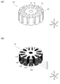
- FIG. 1A is a plan view showing a magnetic core according to an embodiment (first embodiment) of the present invention.
- FIG. 1 (b) is a diagram showing a core assembly included in FIG. 1 (a).
- FIG. 2 (a) is a diagram showing a block strip included in the core assembly shown in FIG. 1 (b).
- FIG. 2B is a plan view of the block strip.
- the magnetic core 100 has the shape of a motor stator. Specifically, the magnetic core 100 has a cylindrical main body 10 having a through hole 20 passing through a central axis along the Z1-Z2 direction, and a radial (inward direction in the XY plane) from the outer surface of the cylindrical main body 10. It has a plurality of extending teeth 30 and.
- the magnetic core 100 shown in FIG. 1 has 12 teeth 30, and a tip portion 40 having a protruding portion protruding in the circumferential direction is located at the outer end portion of each tooth 30.
- the magnetic core 100 is a core assembly 50 made of a soft magnetic material shown in FIG. 1 (b) coated with an impregnation coat.
- the impregnation coat is formed by adhering a coating material made of a resin-based material to the surface of the core assembly 50 and impregnating it.
- the coating material is made of, for example, an epoxy resin.
- the thickness of the impregnated coat is set so that the magnetic core 100 appropriately covers the core assembly 50, which is a conductor, and has appropriate insulating properties. By way of example without limitation, the thickness of the impregnated coat is 0.1 ⁇ m to 5 ⁇ m.
- the core assembly 50 is composed of a plurality of block strips 51.
- the core assembly 50 shown in FIG. 1 (b) consists of a stack of five block strips 51, 52, 53, 54, 55 in the Z1-Z2 direction.
- the block strip 51 is a laminate of a plurality of nanocrystal strips 511.
- the nanocrystal strip 511 is made of a nanocrystal-containing alloy material.
- the block strip 51 shown in FIG. 2A includes a laminate of n nanocrystal strips 511 in the Z1-Z2 direction.
- the shape of the block strip 51 in a plan view is the same as that of the magnetic core 100, and penetrates through the center of the circular main body 11. Twelve teeth 31 radially extend from the outer surface of the main body portion 11 and have a portion 21, and a tip portion 41 having a protruding portion protruding in the circumferential direction is located at the outer end portion of each tooth 31.
- the block strip 51 has a fixing portion 51B in which adjacent nanocrystal strips are fixed to each other in the stacking direction (Z1-Z2 direction).
- the fixing portion 51B is provided on a part of the tip portions 41 of the four teeth 31.
- the fixing portion 51B is composed of a laser welded portion.
- the core assembly 50 shown in FIG. 1B is manufactured by arranging a plurality of block strips 51 prepared as an integral body of the plurality of nanocrystal strips 511.
- the block strip 51 problems such as breakage are less likely to occur in the nanocrystal strips as compared with the case where the nanocrystal strips are laminated one by one to form a laminated core, and as a result, the core assembly 50 is impregnated. It is possible to improve the quality of the magnetic core 100 which is a coated body.
- the size of the entire core assembly 50 can be easily adjusted by changing the number of arrangements of the block strips 51, which are easy to handle, and specifically by changing the number of layers. Therefore, it is possible to easily manufacture the magnetic core 100 having different magnetic characteristics. Further, since the magnetic characteristics of the magnetic core 100 can be changed only by changing the number of layers of the core assembly 50, the magnetic characteristics of the magnetic core 100 can be changed without changing the heat treatment conditions of the amorphous thin band laminate. .. As described above, if the number of layers of the amorphous ribbon is changed, it is necessary to newly set the heat treatment conditions. Therefore, the magnetic core 100 according to the present embodiment is compared with the magnetic core manufactured by such a method. Has excellent quality stability and productivity.
- the fixing portion 51B of the block strip 51 is a laser welded portion, the adjacent nanocrystal strips 511 and 511 are electrically connected through the fixing portion 51B. Therefore, when an eddy current flows through the magnetic core 100, the short-circuit path of the eddy current is in units of 51 block strips. That is, since the core assembly 50 of the magnetic core 100 has a structure in which a plurality of block strips 51 are arranged, the short-circuit path is a block strip 51 unit. Therefore, it is possible to relatively reduce the eddy current loss generated in the magnetic core 100.
- the fixing method of the fixing portion 51B is not limited. Adjacent nanocrystal strips in the block strip 51 may be fixed by an adhesive.
- the fixing portion 51B When the fixing portion 51B is located so as to include the side surface of the nanocrystal thin band 511, the fixing portion 51B may be a cut portion of the nanocrystal thin band 511.
- FIG. 3A is an example of the fixing portion 51B provided on the block strip 51, in which the laminated body of the nanocrystal strip 511 was cut (cut mark 51C) and welded (fixed portion 51B) at the same time. It is a figure which shows the case (fusing).
- FIG. 3B is another example of the fixing portion 51B provided on the block strip 51, in which a part of the cut surface of the laminated body of the nanocrystal strip 511 is welded to form the fixing portion 51B. It is a figure which shows.
- the five block strips 51, 52, 53, 54, 55 arranged along the first direction (Z1-Z2 direction) are the fixing portions 51B, 52B, respectively.
- 53B, 54B, 55B have a shift-arranged block ribbon group having a portion not aligned in the first direction (Z1-Z2 direction).
- the block strip 51 has four anchors 51B, all of which are located on the protrusions 42 of the tip 41 of the teeth 31 and the block 51.
- the fixing portions 51B are arranged every other in the twelve teeth 31 possessed by the above.
- the two adjacent block strips do not have the two fixing portions 51B and 52B lined up in the first direction (Z1-Z2 direction).
- the fixing portions 51B, 52B, 53B, 54B, 55B have different magnetic properties from other portions. Even so, it is expected that spatial variation in the magnetic properties of the core assembly 50 will be less likely to occur.
- FIG. 4 is a diagram showing one of the modified examples of the core assembly included in the magnetic core according to the embodiment of the present invention.
- the fixing portions of the adjacent block strips may be arranged in the first direction (Z1-Z2 direction). Again, because there is magnetic continuity but no electrical continuity between the two adjacent block strips, the short circuit path of the core assembly 501 is the block strips 51, 52, 53, 54, 55, respectively. It becomes a unit of.
- the fixing portion is not provided on the outermost surface of the core assembly 502, and the side surface located inside the outermost surface is provided.
- a fixing portion is provided.
- the fixing portions 51B, 53B, 54B, 55B are provided on one side surface of the circumferential protrusion 42 at the tip portion 41 of the teeth 31.
- a magnetic path may be set so as to penetrate the outermost surface of the core assembly 502.
- the passage of the magnetic path through the fixed portion may affect the characteristics of the magnetic component (for example, the rotational characteristics of the motor). be. Since the core assembly 502 is not provided with a fixing portion on the outer side surface of the protrusion 42 corresponding to the outermost surface, it is expected that the magnetic characteristics of the magnetic core 100 provided with the core assembly 502 will be less affected by the fixing portion. Ru.
- the core assembly 503 shown in FIG. 4C is a main body 11 located in a space (corresponding to a part of the slot SL of the magnetic core 100) between two adjacent teeth 31 in the block strip 51.
- a fixing portion 51B is provided on the outer side surface. When the fixing portion 51B is provided at this position, the influence of the generation of the fixing portion 51B on the block thin band 51 can be reduced as compared with the case where the fixing portion 51B is provided on a part of the teeth 31.
- the teeth 31 may be partially deformed (solidified after melting) due to the heat given by the laser welding, but the core In the case of the assembly 503, even if deformation occurs when the fixing portion 51B is formed by laser welding, since the fixing portion 51B is provided in the main body portion 11, the magnetic characteristics of the magnetic core 100 by the fixing portion 51B can be obtained.
- the influence of the above can be smaller than that in the case where the fixing portion 51B is formed on a part of the teeth 31.
- the nanocrystal strip 511 is a strip made of a nanocrystal-containing alloy material obtained by nanocrystallizing an amorphous strip made of an amorphous alloy material by heat treatment.
- the nanocrystals contained in the nanocrystal ribbon have the bcc-Fe phase as the main phase.
- the plurality of nanocrystal strips 511 constituting the block strip 51 can be obtained by temporarily heat-treating a laminate of amorphous strips corresponding to the block strip 51.
- the thickness of the block strip 51 is set to a thickness capable of forming the nanocrystal strip 511 from the amorphous strip by this heat treatment.
- the layered body of the amorphous thin band becomes thick, the heat generated when the amorphous thin band crystallizes is less likely to be released to the outside of the laminated body, and the controllability of the heat treatment is lowered. Therefore, from the viewpoint of appropriately advancing the heat treatment, it is preferable to set an upper limit on the thickness of the block strip 51.
- the nanocrystal ribbon 511 produced by the heat treatment is hard and brittle, it is preferable that a certain number of nanocrystal ribbons 511 are laminated in the laminate produced by the heat treatment from the viewpoint of improving the handleability. From this viewpoint, it is preferable to set the lower limit of the thickness of the block strip 51.
- the thickness of the block strip 51 is preferably 3 mm or less, and may be preferably 2 mm or less. Further, the thickness of the block strip 51 may be preferably 200 ⁇ m or more, and more preferably 500 ⁇ m or more.
- FIG. 5 is a flowchart showing an example of a method for manufacturing a magnetic core according to an embodiment (first embodiment) of the present invention.
- an amorphous ribbon is manufactured by a single roll method or the like (step S101).
- the obtained amorphous strip is cut to an appropriate length, and the obtained strip is punched to obtain the shape shown in FIG. 2 in a plan view (shape seen from the Z1-Z2 direction).
- a punching member to have is obtained (step S102).
- a plurality of the obtained punched members are laminated to obtain a laminated body (step S103).
- the amorphous ribbon has toughness more than the nanocrystal strip after heat treatment, chipping of the strip is less likely to occur even if the laminating work is performed.
- a block body is obtained by performing a block formation step of laser welding the outer surface of the obtained laminated body at a plurality of places (step S104).
- the obtained block body is heat-treated to obtain a block strip 51 (step S105).
- the conditions of the heat treatment are that crystallization proceeds appropriately in all of the amorphous strips constituting the block body, and defects caused by the heat generated by the crystallization (generation of unnecessary substances such as compounds, burning, etc.) ) Is set to be appropriately suppressed.
- a plurality of block strips 51 obtained by heat treatment are laminated to obtain the core assembly 50 shown in FIG. 1 (b).
- the blocking portion 21 penetrates the block strip 52 adjacent to the block strip 51 so that the adjacent fixing portions (for example, the fixing portion 51B and the fixing portion 52B) do not line up in the first direction (Z1-Z2 direction).
- Rotational laminating is performed by rotating and laminating around the central axis of the above (step S106).
- the magnetic core 100 is obtained by performing a secondary heat treatment (step S107) on the core assembly 50 as necessary and then performing an impregnation coating (step S108). After the impregnation coating is applied, shape adjustment such as deburring may be performed as necessary (step S109).
- FIG. 6 is a flowchart showing another example of the method for manufacturing a magnetic core according to an embodiment of the present invention.
- FIG. 8A is an explanatory diagram of a process for manufacturing a hoop material made of an amorphous ribbon for forming a nanocrystal ribbon included in the magnetic core according to the embodiment of the present invention.
- FIG. 8B is an explanatory diagram of the configuration of a hoop material made of an amorphous ribbon manufactured by the manufacturing process of FIG. 8A.
- FIG. 8 (c) is a diagram illustrating a punched portion of a hoop material made of an amorphous ribbon shown in FIG. 8 (b).
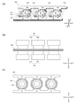
- FIG. 9A is a diagram showing a coupled laminate obtained by subdividing a hoop material made of an amorphous ribbon shown in FIG. 8B.
- FIG. 9B is a diagram illustrating the heat treatment of the coupled laminate of FIG. 9A.
- FIG. 9 (c) is a diagram showing the arrangement of the heat treatment apparatus in the heat treatment of FIG. 9 (b).
- an amorphous strip is first manufactured by a single roll method or the like in the same manner as in the manufacturing method shown in the flowchart of FIG. 5 (step S201). Since the obtained amorphous ribbon has higher toughness than the nanocrystal strip, the obtained amorphous strip is wound into a roll (amorphous roll 201).
- FIG. 8A shows a method for manufacturing the roll-to-roll hoop material 205.
- the amorphous strip 202 is fed out from the amorphous roll 201 in one direction (specifically, the X1-X2 direction X1 side), and the amorphous strip 202 is punched by a punching die (upper die 203, lower die 204). conduct.
- the obtained hoop material 205 has a core strip portion 300 which is finally a direct component of the magnetic core 100 and an in-plane direction of the core strip portion 300 ( Specifically, the punching portion 350 including the base material portion 211 extending in the X1-X2 direction and the connecting rail 212 connecting the core strip portion 300 and the base material portion 211 extends in the direction in which the base material portion 211 extends (specifically, in the X1-X2 direction). They are arranged side by side in the X1-X2 direction).
- the base material portion 211 is provided with a hole for positioning (positioning portion 213).
- the shape of the core strip portion 300 of the punching portion 350 in a plan view is similar to that of the block strip 51, and is circular.
- a penetrating portion 320 is provided at the center of the main body portion 310, twelve teeth 330 extend radially from the outer surface, and a tip portion 340 having a protruding portion 341 protruding in the circumferential direction is provided at the outer end portion of each tooth 330.
- some of the connecting bars 212 project in the circumferential direction (Y1-Y2 direction) at the tip portions 340 of the two teeth 330 extending along the X1-X2 direction.
- the other part of the connecting rail 212 is provided so as to connect to the protruding portion 341 protruding in the circumferential direction (X1-X2 direction) at the tip portion 340 of the two teeth 330 extending along the Y1-Y2 direction. ing. Therefore, the cut portion CP of the connecting rail 212 is not positioned so as to be connected to the outermost surface of the tip portion 340. Therefore, as shown in FIG. 4B, the block strip 51 obtained from the punching portion 350 shown in FIG. 8C is fixed to the outermost surface of the core strip 51B after cutting. That is, the cutting mark 51C) is not located.
- the crystal state of the cutting mark 51C may change from that of other parts regardless of whether the cutting method is laser or mechanical cutting. Therefore, the magnetic core 100 may have different magnetic characteristics from other parts in the portion where the cutting mark 51C is located. Therefore, when the magnetic path of the magnetic circuit of the magnetic component including the magnetic core 100 passes through the cutting mark 51C, the magnetic characteristics change in that portion, and as a result, the stability of the magnetic characteristics of the magnetic component is affected. May reach. It is possible to minimize these effects by optimizing the cutting method.
- a magnetic path may pass through the outermost surface thereof. For example, the punching portion 350 shown in FIG. 10 (a). Since the core assembly 502 shown in FIG. 4B is obtained, the possibility that the magnetic path of the magnetic circuit of the magnetic component passes through the cutting mark 51C can be further reduced.
- the hoop material 205 obtained by punching is wound up into a roll material 206.
- the hoop material 205 is fed out from the roll material 206 and cut into small pieces to obtain a coupled member 251 to which a predetermined number (for example, 3) of punching parts 350 are connected (step S203).
- a predetermined number for example, 3
- a plurality of the obtained coupled members 251 are laminated in the Z1-Z2 direction to obtain a coupled laminated body 360 (step S204).
- a plurality of coupled members 251 can be easily laminated in the Z1-Z2 direction without touching the core thin band portion 300.
- the obtained coupled laminated body 360 is heat-treated (step S205).
- a plurality of sets of heat treatment devices 395, 396 are set according to the number of laminated bodies of the core strip portion 300 included in the coupled member 251 of the coupled laminated body 360. Is prepared, and the laminated body of the core thin band portion 300 is sandwiched between the heat treatment devices 395 and 396 of each set from the laminating direction (Z1-Z2 direction) of the coupled laminated body 360.
- the heat treatment apparatus 395 and 396 are for controlling the temperature of the core zonal portion 300, and have a substantially columnar shape, respectively, and heat reservoirs 370 and 371 that are in direct contact with the core zonal portion 300. It is provided with heater blocks 390 and 391 for heating the heat reservoirs 370 and 371. As a result, the heat treatment apparatus 395 and 396 have a function of applying heat to the core thin band portion 300 and a function of receiving heat from the core thin band portion 300. By arranging a plurality of a set of heat treatment devices 395 and 396 in this way, it is possible to make the conditions of the heat treatment applied to each of the laminated bodies of the plurality of core strips 300 of the coupled laminated body 360 equal.
- the heat treatment conditions are such that crystallization proceeds appropriately in all the amorphous strips constituting the core strip portion 300 of the coupled laminate 360, and defects (unnecessary substances such as compounds) caused by the heat generated by the crystallization occur. (Generation, burning, etc.) are set to be appropriately suppressed.
- the amorphous ribbon constituting the core strip portion 300 of the coupled laminate 360 is crystallized into a nanocrystal strip 511.
- the connecting portion (cutting portion CP) with the connecting rail 212 in the protruding portion 341 is laser-fused to separate the laminated body of the core thin band portion 300 (nanocrystal thin band 511), and this laminated body is formed.
- a plurality of nanocrystal strips 511 are fixed to obtain the block strips 51 shown in FIG. 4 (b) (step S206). Therefore, the fixing portion 51B of the block strip 51 manufactured by the manufacturing method shown in the flowchart of FIG. 6 is also a cutting mark 51C.
- step S207 rotational lamination
- step S208 a secondary heat treatment
- step S208 an impregnation coating
- step S210 shape adjustment
- FIG. 10 (a) is a diagram illustrating a modified example of the heat treatment of the coupled laminate of FIG. 9 (b), and FIG. 11 (b) shows the shape of the heating member used for the heat treatment of FIG. 10 (a). It is a plan view which represents.
- the cut portion CP when the heat reservoirs 370 and 371 provided in the heat treatment apparatus 395 and 396 have a substantially cylindrical shape, as shown in FIG. 9 (c), the cut portion CP. (See FIG. 8 (c)) is in direct contact with the heat reservoir 370. Therefore, in the coupled laminate 360 after the heat treatment step (step S205), the cut portion CP is also heat-treated and crystallized. Therefore, the cutting portion CP may have a reduced cutting workability. As described above, the protruding portion 341 to which the cutting portion CP is connected is unlikely to pass a magnetic path, but if the cutting workability is lowered, the shape uniformity of the cutting mark 51C is lowered and the block is thin. It may affect the maintenance of the shape quality of the band 51.
- the heat treatment step if the plan view shape of the heat reservoirs 370A and 371A (shape seen from the Z1-Z2 direction) corresponds to the plan view shape of the core lamellae portion 300, the heat treatment step.
- step S205 the portion of the connecting rail 212 connected to the protruding portion 341 of the tip portion 340 is not heat-treated and remains an amorphous alloy. Therefore, the coupled laminated body 360 after the heat treatment has good cutting workability of the cutting portion CP, and as shown in FIG. 4B, the side surface of the protruding portion 341 of the tip portion 340 of the block strip 51. Even if the fixing portion 51B is positioned in the position, the shape quality is unlikely to deteriorate.
- FIG. 7 is a flowchart showing another example of the method for manufacturing a magnetic core according to an embodiment of the present invention.
- the “separate cutting / blocking” step of step S206 is divided into a separation cutting step (step S206A) and a blocking step (step S206B) in comparison with the flowchart shown in FIG. It differs in that it is done.
- the separation cutting step is performed by, for example, mechanical cutting
- the blocking step is performed by, for example, laser welding.
- the heat treatment step (step S205) is performed after the blocking step (step S206B) in comparison with the flowchart shown in FIG. When the portion made of an amorphous alloy undergoes the heat treatment step (step S205), it is nanocrystallized and the cutting processability is lowered.
- step S206A the separation cutting step
- step S206B the blocking step
- FIG. 11A is a plan view showing an example of a block strip manufactured by the manufacturing method shown in the flowchart of FIG. 7.
- FIG. 11B is a diagram illustrating a fixed portion of the block strip of FIG. 11A.
- the block strip 510 shown in FIG. 11 has a cut balance 214 at the outer end of the tip 41 of the teeth 31.
- the cutting residue 214 is the cutting residue when the cutting portion CP of the connecting rail 212 is cut in the separation cutting step (step S206A).
- the fixing portion 51B is laser-welded to the outer surface of the main body portion 11 forming the space corresponding to the slot SL, similarly to the core assembly 503 shown in FIG. 4 (c). It is provided by.
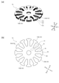
- FIG. 12 (a) is a plan view showing the shape of an amorphous strip for forming a core assembly included in the magnetic core according to another embodiment (second embodiment) of the present invention.
- FIG. 12 (b) is a diagram showing the shape of the block strip formed from the amorphous strip of FIG. 12 (a).
- 13 (a) is a diagram showing a core assembly with the block strip of FIG. 12 (b).
- FIG. 13 (b) is a diagram showing a core assembly obtained by further combining the core assemblies of FIG. 13 (a).
- the block strips 70 are arranged side by side in directions other than the stacking direction (Z1-Z2 direction) of the nanocrystal strips 60 constituting the block strips 70. There is.
- the nanocrystal ribbon 60 has a main body portion 61 having a shape in which the annulus is divided into four halves, and the main body portion 61 in the circumferential direction of the annulus. It is provided with a convex portion 62 protruding toward the surface, a concave portion 63 recessed in the circumferential direction of the annulus in the main body 61, and a tooth 64 projecting from the inner peripheral side of the annulus to the center side of the annulus.
- the convex portion 62 and the concave portion 63 have a shape that allows them to be fitted so that they can be connected to another nanocrystal ribbon 60.
- the block strip 70 having the fixing portion 70B can be obtained.
- the block strip 70 has a fitting protrusion 71 based on the convex portion 62 of the nanocrystal strip 60 and a fitting recess based on the recess 63 of the nanocrystal strip 60 so that the block strip 70 can be fitted with another block strip 70.
- 72 With 72.
- the core assembly 90 has a ring assembly 80 in which four block strips 70 are fitted in the fitting portion 80C and the entire shape is annular.
- the arrangement direction of the block strips 70 in the ring assembly 80 is different from the stacking direction (Z1-Z2 direction) of the nanocrystal strips 60.
- a plurality of ring assemblies three ring assemblies 81, 82, 83 in FIG. 13 (b) are laminated to form the core assembly 90.
- the fixing portions 81B, 82B, and 83B of the core assembly 90 derived from the fixing portion 70B of the block strip 70 are arranged in the stacking direction (Z1-Z2 direction), but the core assembly 90 is electrically operated for each block strip 70.
- the short circuit path is limited to the block strip 70 because it is separated into. Therefore, the magnetic core provided with the core assembly 90 is unlikely to have a large eddy current loss.
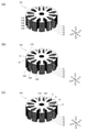
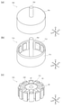
- FIG. 14A is an external view of a motor which is an example of a magnetic product in which a magnetic component provided with a magnetic core according to an embodiment of the present invention is used.
- 14 (b) is an external view of a rotor which is one of the magnetic parts included in the motor of FIG. 14 (a).
- 14 (c) is an external view of a stator which is another magnetic component included in the motor of FIG. 14 (a).
- a rotation shaft 702 passing through the center of the bottom surface of the motor body 701 having a cylindrical shape protrudes to the Z1 side in the Z1-Z2 direction.
- the rotor 710 shown in FIG. 14B is rotatably arranged around the rotation axis in the Z1-Z2 direction.
- the rotor 710 is fixed to a rotor main body 711 having a hollow cylindrical shape in which one of the bottom surfaces (Z1-Z2 direction Z1 side) is open and a central portion of the bottom surface of the other (Z1-Z2 direction Z2 side) of the rotor main body 711. It is provided with a rotating shaft 702.
- a plurality of magnets 712 are arranged side by side in the circumferential direction on the inner wall surface of the rotor main body 711.
- a stator 720 having a columnar outer shape is arranged between the rotor main body 711 of the rotor 710 and the rotating shaft 702.
- the stator 720 includes a magnetic core 100 according to an embodiment of the present invention, and a coil 721 wound around each of the plurality of teeth 30 thereof.
- a rotation shaft 702 is inserted through the through hole 20 of the magnetic core 100.
- the magnet 712 of the rotor 710 is provided on the inner side wall of the rotor main body 711 so as to face each of the tip portions 40 of the teeth 30 of the magnetic core 100.
Abstract
The magnetic core 100 according to the present invention has a structure in which thin nanocrystal bands are layered, and has a magnetic characteristic that is easily stabilized. The magnetic core 100 is provided with a core assembly 50 that has a structure in which a plurality of thin block bands 51 each including a layered product of a plurality of thin nanocrystal bands 511 made of a nanocrystal-containing alloy material are disposed. Each of the thin block band 51 has a fixation part 51B in which the thin nanocrystal bands 511, 511 adjacent to each other in the lamination direction are fixed together. The fixation part 51B may include a side surface of a thin nanocrystal band 511, and may comprise a laser welded portion.
Description
本発明は、磁性コアおよびかかる磁性コアを備える磁気部品に関する。
The present invention relates to a magnetic core and a magnetic component including such a magnetic core.
特許文献1には、アモルファス合金薄帯の積層体を保持する積層治具と、前記積層治具と接触することなく前記積層体を積層方向の上下面から挟み込む2つの加熱プレートと、前記2つの加熱プレートを加熱温度制御するための加熱制御装置と、を備えた、アモルファス合金薄帯の積層体の熱処理装置が開示されている。この熱処理装置を用いてアモルファス合金薄帯の積層体を加熱処理することにより、Fe基ナノ結晶合金の薄帯の積層体を備える磁性コアを得ることができる。
Patent Document 1 describes a laminating jig that holds a laminated body of amorphous alloy strips, two heating plates that sandwich the laminated body from the upper and lower surfaces in the laminating direction without contacting the laminating jig, and the two heating plates. Disclosed is a heat treatment device for a laminate of amorphous alloy strips, comprising a heating control device for controlling the heating temperature of the heating plate. By heat-treating the laminate of amorphous alloy strips using this heat treatment apparatus, a magnetic core having the laminate of Fe-based nanocrystal alloy strips can be obtained.
特許文献2には、複数の磁性板が積層され、モータの回転方向に沿って山部と溝部とが交互に形成された表面凹凸形状の磁極を備えたモータの積層コアにおいて、前記磁極に形成された前記溝部の表面に前記磁性板を相互に固着する溶着部が設けられていることを特徴とするモータの積層コアが開示されている。
In Patent Document 2, a plurality of magnetic plates are laminated, and peaks and grooves are alternately formed along the rotation direction of the motor. A laminated core of a motor is disclosed, characterized in that a welded portion for fixing the magnetic plates to each other is provided on the surface of the grooved portion.
特許文献1に記載されるようなアモルファス合金薄帯の積層体を熱処理すると、アモルファス合金薄帯の結晶化の際に熱が発生する。この熱を適切に制御しないと、得られたナノ結晶合金の薄帯(ナノ結晶薄帯)の積層体の磁気特性が適切に向上しなかったり、熱暴走が生じて薄帯が焼損したりすることがある。アモルファス合金薄帯の積層体の積層数は熱処理において積層体に生じる熱と関連するとともに、積層体の積層数は積層体を備える磁性コアの磁気特性にも深く関連する。このため、磁気特性が異なる複数種類の磁性コアを得るべく積層数の異なる積層体を用意すると、積層体ごとに熱処理条件を個別に設定する必要がある。積層体として熱処理せずにアモルファス合金薄帯を枚葉で熱処理すると、熱処理により得られたナノ結晶薄帯は脆いため取り扱い性が低く、ナノ結晶薄帯を積層する工程において割れや欠けといった破損が生じやすく、磁性コアの品質を確保する観点で問題がある。
When a laminate of amorphous alloy strips as described in Patent Document 1 is heat-treated, heat is generated during crystallization of the amorphous alloy strips. If this heat is not properly controlled, the magnetic properties of the obtained laminate of nanocrystal alloy strips (nanocrystal strips) will not be properly improved, or thermal runaway will occur and the strips will burn out. Sometimes. The number of layers of the amorphous alloy strip is related to the heat generated in the layer during heat treatment, and the number of layers of the layer is deeply related to the magnetic properties of the magnetic core provided with the layer. Therefore, if laminated bodies having different numbers of layers are prepared in order to obtain a plurality of types of magnetic cores having different magnetic characteristics, it is necessary to individually set heat treatment conditions for each layered body. When the amorphous alloy strip is heat-treated with a single leaf without heat treatment as a laminate, the nanocrystal strip obtained by the heat treatment is fragile and difficult to handle, and the nanocrystal strip is damaged in the process of laminating the nanocrystal strip. It tends to occur, and there is a problem in terms of ensuring the quality of the magnetic core.
本発明は、ナノ結晶薄帯が積層された構造を有する磁性コアであって、磁気特性が安定しやすい磁性コアを提供することを目的とする。本発明は、かかる磁性コアを備える磁気部品を提供することも目的とする。
An object of the present invention is to provide a magnetic core having a structure in which nanocrystal ribbons are laminated and whose magnetic characteristics are easily stabilized. It is also an object of the present invention to provide a magnetic component including such a magnetic core.
上記の課題を解決するための本発明は、一態様において、ナノ結晶含有合金材料からなるナノ結晶薄帯の複数の積層体からなるブロック薄帯が複数配置された構造を有するコアアセンブリを備える磁性コアであって、前記ブロック薄帯は、積層方向に隣り合う前記ナノ結晶薄帯が互いに固着された固着部を有することを特徴とする磁性コアである。
In one aspect, the present invention for solving the above problems includes a magnetism having a core assembly having a structure in which a plurality of block strips composed of a plurality of laminates of nanocrystal strips made of a nanocrystal-containing alloy material are arranged. The core is a magnetic core characterized in that the block strips have a fixing portion in which the nanocrystal strips adjacent to each other in the stacking direction are fixed to each other.
複数のナノ結晶薄帯が積層されたブロック薄帯を用意し、このブロック薄帯を複数配置してコアアセンブリ(コア組立体)を作製することが可能となるため、ナノ結晶薄帯を一枚ずつ積層して積層コアを形成した場合に比べて、ナノ結晶薄帯に破損などの不具合が生じにくく、結果、コアアセンブリの含浸コート体である磁性コアの品質を高めることが可能となる。
Since it is possible to prepare a block strip in which multiple nanocrystal strips are laminated and arrange multiple block strips to form a core assembly (core assembly), one nanocrystal strip can be used. Compared with the case where the laminated cores are formed by laminating them one by one, defects such as breakage are less likely to occur in the nanocrystal ribbon, and as a result, the quality of the magnetic core which is the impregnated coated body of the core assembly can be improved.
コアアセンブリがブロック薄帯におけるナノ結晶薄帯の積層方向に沿って配置された場合には、コアアセンブリに配置される複数のブロック薄帯の並び方向(並び方向)は、ブロック薄帯を構成する複数のナノ結晶薄帯の積層方向(積層方向)に沿い、従来の積層コアのようにナノ結晶薄帯が多数積層された構造を有するが、所定枚数ごとに固着部により一体化された部分(ブロック薄帯)を複数備える点で、従来の積層コアとは相違する。
When the core assembly is arranged along the stacking direction of the nanocrystal zonules in the block zonules, the arrangement direction (arrangement direction) of the plurality of block zonules arranged in the core assembly constitutes the block zonules. Along the stacking direction (stacking direction) of a plurality of nanocrystal strips, it has a structure in which a large number of nanocrystal strips are laminated like a conventional laminated core, but a portion integrated by a fixing portion for each predetermined number (a portion). It differs from the conventional laminated core in that it has a plurality of block strips).
このように、コアアセンブリが複数のブロック薄帯の組立体であることにより、ブロック薄帯の固着部が例えば溶接などにより形成されて導電性を有する場合でも、コアアセンブリを備える磁性コアの短絡経路はブロック薄帯により分割される。特許文献2に記載されるように複数の薄帯を溶接などにより一体化すると、得られた磁性コアは電気的にも一体化するため、磁性コアの短絡経路が長くなる。短絡経路が長いほど、磁性コアの渦電流損が大きくなるため、短絡経路ブロック薄帯単位に分割される本発明に係る磁性コアは、鉄損、特に渦電流損が高まりにくい。
As described above, since the core assembly is an assembly of a plurality of block strips, a short-circuit path of the magnetic core including the core assembly is provided even when the fixed portion of the block strips is formed by welding, for example, and has conductivity. Is divided by the block strip. When a plurality of thin strips are integrated by welding or the like as described in Patent Document 2, the obtained magnetic core is also electrically integrated, so that the short-circuit path of the magnetic core becomes long. The longer the short-circuit path, the larger the eddy current loss of the magnetic core. Therefore, the magnetic core according to the present invention, which is divided into short-circuit path block strip units, is less likely to have iron loss, particularly eddy current loss.
なお、コアアセンブリを構成する複数のブロック薄帯の並び方向と、ブロック薄帯におけるナノ結晶薄帯の積層方向との関係は任意である。並び方向と積層方向とが揃っていてもよいし、揃っていなくてもよい。
The relationship between the arrangement direction of the plurality of block strips constituting the core assembly and the stacking direction of the nanocrystal strips in the block strips is arbitrary. The arrangement direction and the stacking direction may or may not be aligned.
上記の磁性コアにおいて、前記固着部は前記ナノ結晶薄帯の側面を含んでいてもよい。固着部の視認が容易であり、ブロック薄帯の固着状態を確認しやすい。
In the above magnetic core, the fixing portion may include the side surface of the nanocrystal ribbon. It is easy to visually recognize the fixed portion, and it is easy to confirm the fixed state of the block thin band.
上記の磁性コアにおいて、前記固着部はレーザ溶接部からなっていてもよい。固着部におけるナノ結晶薄帯の固着が安定しているため、ブロック薄帯の取り扱い性が高まり、コアアセンブリを作製すべく複数のブロック薄帯を配置する工程の途中で破損するなどの不具合が生じにくい。
In the above magnetic core, the fixed portion may be composed of a laser welded portion. Since the nanocrystal strips are stably fixed at the anchored part, the handleability of the block strips is improved, and problems such as breakage occur during the process of arranging multiple block strips to fabricate the core assembly. Hateful.
上記の磁性コアにおいて、前記ナノ結晶薄帯は、アモルファス合金材料からなるアモルファス薄帯を熱処理によりナノ結晶化させて得られたものであってもよい。この場合において、前記ブロック薄帯の厚さは、前記アモルファス薄帯が前記熱処理により前記ナノ結晶薄帯を生成しうる厚さであることが好ましい。ブロック薄帯の厚さが過度に大きい場合には、アモルファス薄帯を熱処理した際に温度制御が不能となり、ブロック薄帯が焼損してしまうことが懸念される。具体的には、前記ブロック薄帯の厚さは3mm以下であることが、アモルファス薄帯の熱処理の制御しやすさの観点から好ましい場合がある。
In the above magnetic core, the nanocrystal strip may be obtained by nanocrystallizing an amorphous strip made of an amorphous alloy material by heat treatment. In this case, the thickness of the block strip is preferably such that the amorphous strip can generate the nanocrystal strip by the heat treatment. If the thickness of the block strip is excessively large, the temperature cannot be controlled when the amorphous strip is heat-treated, and there is a concern that the block strip may be burnt out. Specifically, it may be preferable that the thickness of the block strip is 3 mm or less from the viewpoint of ease of controlling the heat treatment of the amorphous strip.
上記の磁性コアにおいて、前記ナノ結晶薄帯に含まれるナノ結晶はbcc-Fe相を主相としてもよい。高い飽和磁束密度を持ちつつナノ結晶化によるランダム磁気異方性の効果により良好な軟磁性特性が得られる。
In the above magnetic core, the nanocrystals contained in the nanocrystal ribbon may have the bcc-Fe phase as the main phase. Good soft magnetic properties can be obtained due to the effect of random magnetic anisotropy by nanocrystallization while having a high saturation magnetic flux density.
第1方向に沿って並ぶ複数の前記ブロック薄帯からなり、複数の前記ブロック薄帯の前記固着部が前記第1方向に並ばない部分を有するシフト配置ブロック薄帯群を、上記の磁性コアは有していてもよい。第1方向の一具体例はナノ結晶薄帯の厚さ方向である。固着部は他の部分に比べて磁気特性が異なる場合がありうるが、そのような場合でも、コアアセンブリに含まれる複数の固着部が一方向に並ばないようにブロック薄帯を配置することにより、コアアセンブリを備える磁性コアの磁気特性の均一性を高めることができることがある。
The magnetic core is a shift-arranged block band group composed of a plurality of the block strips arranged along the first direction and having a portion in which the fixed portions of the plurality of block strips do not line up in the first direction. You may have. One specific example of the first direction is the thickness direction of the nanocrystal ribbon. The fixed part may have different magnetic properties than the other parts, but even in such a case, by arranging the block strip so that the plurality of fixed parts contained in the core assembly do not line up in one direction. , It may be possible to increase the uniformity of the magnetic properties of a magnetic core with a core assembly.
上記の磁性コアにおいて、前記コアアセンブリは含浸コートされていてもよい。コアアセンブリが含浸コートされていれば、コアアセンブリから薄帯が剥離する不具合が生じにくい。
In the above magnetic core, the core assembly may be impregnated coated. If the core assembly is impregnated and coated, the problem that the thin band is peeled off from the core assembly is unlikely to occur.
本発明は、他の一態様として、上記の磁性コアを備えることを特徴とする磁気部品を提供する。
The present invention provides, as another aspect, a magnetic component including the above-mentioned magnetic core.
本発明によれば、ナノ結晶薄帯が積層された構造を有し、磁気特性が安定しやすい磁性コアが提供される。また、本発明により上記の磁性コアを備える磁気部品も提供される。
According to the present invention, there is provided a magnetic core having a structure in which nanocrystal ribbons are laminated and whose magnetic characteristics are easy to stabilize. The present invention also provides a magnetic component provided with the above magnetic core.
以下、図面を参照しつつ本発明の実施形態について説明する。なお、以下の説明では、同一の部材には同一の符号を付し、一度説明した部材については適宜その説明を省略する。
Hereinafter, embodiments of the present invention will be described with reference to the drawings. In the following description, the same members are designated by the same reference numerals, and the description of the members once described will be omitted as appropriate.
図1(a)は、本発明の一実施形態(第1実施形態)に係る磁性コアを表す平面図である。図1(b)は、図1(a)が備えるコアアセンブリを表す図である。図2(a)は、図1(b)に示されるコアアセンブリが備えるブロック薄帯を表す図である。図2(b)は、ブロック薄帯の平面図である。
FIG. 1A is a plan view showing a magnetic core according to an embodiment (first embodiment) of the present invention. FIG. 1 (b) is a diagram showing a core assembly included in FIG. 1 (a). FIG. 2 (a) is a diagram showing a block strip included in the core assembly shown in FIG. 1 (b). FIG. 2B is a plan view of the block strip.
第1実施形態に係る磁性コア100は、図1(a)に示されるように、モータのステータの形状を有する。具体的は、磁性コア100は、Z1-Z2方向に沿う中心軸を通る貫通孔20を有する円筒状の本体部10と、円筒状の本体部10の外側面から放射状(XY平面内方向)に延びる複数のティース30とを有する。図1に示される磁性コア100は、12本のティース30を有し、それぞれのティース30の外側端部には周方向に突出する突出部を有する先端部40が位置する。
As shown in FIG. 1A, the magnetic core 100 according to the first embodiment has the shape of a motor stator. Specifically, the magnetic core 100 has a cylindrical main body 10 having a through hole 20 passing through a central axis along the Z1-Z2 direction, and a radial (inward direction in the XY plane) from the outer surface of the cylindrical main body 10. It has a plurality of extending teeth 30 and. The magnetic core 100 shown in FIG. 1 has 12 teeth 30, and a tip portion 40 having a protruding portion protruding in the circumferential direction is located at the outer end portion of each tooth 30.
磁性コア100は、図1(b)に示される軟磁性体からなるコアアセンブリ50に含浸コートが施されたものである。含浸コートは樹脂系材料からなるコート材をコアアセンブリ50の表面に付着させて含浸させることによって形成される。コート材は例えばエポキシ樹脂からなる。含浸コートの厚さは導電体であるコアアセンブリ50を適切に覆って磁性コア100が適切な絶縁性を有するように設定される。限定されない例示をすれば、含浸コートの厚さは0.1μmから5μmである。
The magnetic core 100 is a core assembly 50 made of a soft magnetic material shown in FIG. 1 (b) coated with an impregnation coat. The impregnation coat is formed by adhering a coating material made of a resin-based material to the surface of the core assembly 50 and impregnating it. The coating material is made of, for example, an epoxy resin. The thickness of the impregnated coat is set so that the magnetic core 100 appropriately covers the core assembly 50, which is a conductor, and has appropriate insulating properties. By way of example without limitation, the thickness of the impregnated coat is 0.1 μm to 5 μm.
コアアセンブリ50は、複数のブロック薄帯51から構成される。図1(b)に示されるコアアセンブリ50は、5つのブロック薄帯51、52、53、54、55のZ1-Z2方向の積層体からなる。
The core assembly 50 is composed of a plurality of block strips 51. The core assembly 50 shown in FIG. 1 (b) consists of a stack of five block strips 51, 52, 53, 54, 55 in the Z1-Z2 direction.
ブロック薄帯51は複数のナノ結晶薄帯511の積層体である。ナノ結晶薄帯511はナノ結晶含有合金材料からなる。図2(a)に示されるブロック薄帯51は、n枚のナノ結晶薄帯511のZ1-Z2方向の積層体を備える。図2(b)に示されるように、ブロック薄帯51の平面視の形状(Z1-Z2方向からみた形状)は、磁性コア100と同様であって、円状の本体部11の中心に貫通部21を有し、本体部11の外側面から12本のティース31が放射状に延出し、各ティース31の外側端部には円周方向に突出する突出部を有する先端部41が位置する。
The block strip 51 is a laminate of a plurality of nanocrystal strips 511. The nanocrystal strip 511 is made of a nanocrystal-containing alloy material. The block strip 51 shown in FIG. 2A includes a laminate of n nanocrystal strips 511 in the Z1-Z2 direction. As shown in FIG. 2B, the shape of the block strip 51 in a plan view (shape seen from the Z1-Z2 direction) is the same as that of the magnetic core 100, and penetrates through the center of the circular main body 11. Twelve teeth 31 radially extend from the outer surface of the main body portion 11 and have a portion 21, and a tip portion 41 having a protruding portion protruding in the circumferential direction is located at the outer end portion of each tooth 31.
ブロック薄帯51は、積層方向(Z1-Z2方向)に隣り合うナノ結晶薄帯が互いに固着された固着部51Bを有する。図2(a)に示されるブロック薄帯51では、固着部51Bは、4つのティース31の先端部41の一部に設けられている。本実施形態では、固着部51Bはレーザ溶接部からなる。
The block strip 51 has a fixing portion 51B in which adjacent nanocrystal strips are fixed to each other in the stacking direction (Z1-Z2 direction). In the block strip 51 shown in FIG. 2A, the fixing portion 51B is provided on a part of the tip portions 41 of the four teeth 31. In the present embodiment, the fixing portion 51B is composed of a laser welded portion.
このように、図1(b)に示されるコアアセンブリ50は、複数のナノ結晶薄帯511の一体化物として用意されたブロック薄帯51を複数配置して作製されたものである。ブロック薄帯51を用いることにより、ナノ結晶薄帯を一枚ずつ積層して積層コアを形成した場合に比べて、ナノ結晶薄帯に破損などの不具合が生じにくく、結果、コアアセンブリ50の含浸コート体である磁性コア100の品質を高めることが可能となる。
As described above, the core assembly 50 shown in FIG. 1B is manufactured by arranging a plurality of block strips 51 prepared as an integral body of the plurality of nanocrystal strips 511. By using the block strip 51, problems such as breakage are less likely to occur in the nanocrystal strips as compared with the case where the nanocrystal strips are laminated one by one to form a laminated core, and as a result, the core assembly 50 is impregnated. It is possible to improve the quality of the magnetic core 100 which is a coated body.
また、取り扱い性が容易なブロック薄帯51の配置数を変更することにより、具体的には積層数を変更することにより、コアアセンブリ50全体の大きさを容易に調整することができる。このため、異なる磁気特性を有する磁性コア100を容易に作製することが可能である。さらに、コアアセンブリ50の積層数を変更するだけで磁性コア100の磁気特性を変更できるため、アモルファス薄帯の積層体の熱処理条件を変更することなく、磁性コア100の磁気特性変更が実現される。前述のように、アモルファス薄帯の積層体の枚数を変更すると熱処理条件を新たに設定する必要があるため、このような方法で製造された磁性コアに比べて、本実施形態に係る磁性コア100は、品質の安定性に優れ、生産性にも優れる。
Further, the size of the entire core assembly 50 can be easily adjusted by changing the number of arrangements of the block strips 51, which are easy to handle, and specifically by changing the number of layers. Therefore, it is possible to easily manufacture the magnetic core 100 having different magnetic characteristics. Further, since the magnetic characteristics of the magnetic core 100 can be changed only by changing the number of layers of the core assembly 50, the magnetic characteristics of the magnetic core 100 can be changed without changing the heat treatment conditions of the amorphous thin band laminate. .. As described above, if the number of layers of the amorphous ribbon is changed, it is necessary to newly set the heat treatment conditions. Therefore, the magnetic core 100 according to the present embodiment is compared with the magnetic core manufactured by such a method. Has excellent quality stability and productivity.
上記のとおり、ブロック薄帯51の固着部51Bがレーザ溶接部である場合には、隣り合うナノ結晶薄帯511、511は固着部51Bを通じて電気的に接続される。このため、磁性コア100に渦電流が流れる場合に、渦電流の短絡経路はブロック薄帯51単位となる。すなわち、磁性コア100のコアアセンブリ50は複数のブロック薄帯51が配置された構造を有しているため、短絡経路はブロック薄帯51単位となる。それゆえ、磁性コア100に生じる渦電流損を相対的に少なくすることが可能である。これに対し、例えば特許文献2に記載される積層コアのように、積層コアを構成する複数の磁性板の全体を固着するように溶着部が設けられている場合には、積層コアの短絡経路はその全体となり、渦電流損が大きくなってしまう。
As described above, when the fixing portion 51B of the block strip 51 is a laser welded portion, the adjacent nanocrystal strips 511 and 511 are electrically connected through the fixing portion 51B. Therefore, when an eddy current flows through the magnetic core 100, the short-circuit path of the eddy current is in units of 51 block strips. That is, since the core assembly 50 of the magnetic core 100 has a structure in which a plurality of block strips 51 are arranged, the short-circuit path is a block strip 51 unit. Therefore, it is possible to relatively reduce the eddy current loss generated in the magnetic core 100. On the other hand, when a welded portion is provided so as to fix the entire plurality of magnetic plates constituting the laminated core, as in the case of the laminated core described in Patent Document 2, a short-circuit path of the laminated core is provided. Is the whole, and the eddy current loss becomes large.
固着部51Bの固着方法は限定されない。ブロック薄帯51において隣り合うナノ結晶薄帯は接着剤により固着されていてもよい。固着部51Bがナノ結晶薄帯511の側面を含むように位置する場合には、固着部51Bはナノ結晶薄帯511の切断部であってもよい。そのような場合の具体例として、固着部51Bが溶断部である場合が例示される。図3(a)はブロック薄帯51に設けられた固着部51Bの一例であり、ナノ結晶薄帯511の積層体の切断(切断痕51C)と溶接(固着部51B)とが同時に行われた場合(溶断)を示す図である。図3(b)は、ブロック薄帯51に設けられた固着部51Bの他の一例であり、ナノ結晶薄帯511の積層体の切断面の一部を溶接して固着部51Bとした場合を示す図である。
The fixing method of the fixing portion 51B is not limited. Adjacent nanocrystal strips in the block strip 51 may be fixed by an adhesive. When the fixing portion 51B is located so as to include the side surface of the nanocrystal thin band 511, the fixing portion 51B may be a cut portion of the nanocrystal thin band 511. As a specific example of such a case, a case where the fixing portion 51B is a fusing portion is exemplified. FIG. 3A is an example of the fixing portion 51B provided on the block strip 51, in which the laminated body of the nanocrystal strip 511 was cut (cut mark 51C) and welded (fixed portion 51B) at the same time. It is a figure which shows the case (fusing). FIG. 3B is another example of the fixing portion 51B provided on the block strip 51, in which a part of the cut surface of the laminated body of the nanocrystal strip 511 is welded to form the fixing portion 51B. It is a figure which shows.
図1(b)に示されるコアアセンブリ50では、第1方向(Z1-Z2方向)に沿って並ぶ5つのブロック薄帯51、52、53、54、55は、それぞれの固着部51B、52B、53B、54B、55Bが第1方向(Z1-Z2方向)に並ばない部分を有するシフト配置ブロック薄帯群を有する。図2(b)に示されるように、ブロック薄帯51は4つの固着部51Bを有し、これらの固着部51Bはいずれもティース31の先端部41の突出部42にあり、ブロック薄帯51が有する12個のティース31において2つおきに固着部51Bは配置されている。そして、コアアセンブリ50において隣り合う2つのブロック薄帯(例えばブロック薄帯51、52)はいずれも、2つの固着部51B、52Bが第1方向(Z1-Z2方向)に並んでいない。コアアセンブリ50において複数のブロック薄帯51、52、53、54、55がこのように配置されることにより、固着部51B、52B、53B、54B、55Bが他の部分と磁気的性質が異なる場合であっても、コアアセンブリ50の磁気特性の空間的ばらつきが生じにくくなると期待される。
In the core assembly 50 shown in FIG. 1 (b), the five block strips 51, 52, 53, 54, 55 arranged along the first direction (Z1-Z2 direction) are the fixing portions 51B, 52B, respectively. 53B, 54B, 55B have a shift-arranged block ribbon group having a portion not aligned in the first direction (Z1-Z2 direction). As shown in FIG. 2B, the block strip 51 has four anchors 51B, all of which are located on the protrusions 42 of the tip 41 of the teeth 31 and the block 51. The fixing portions 51B are arranged every other in the twelve teeth 31 possessed by the above. In the core assembly 50, the two adjacent block strips (for example, the block strips 51 and 52) do not have the two fixing portions 51B and 52B lined up in the first direction (Z1-Z2 direction). When a plurality of block strips 51, 52, 53, 54, 55 are arranged in this way in the core assembly 50, so that the fixing portions 51B, 52B, 53B, 54B, 55B have different magnetic properties from other portions. Even so, it is expected that spatial variation in the magnetic properties of the core assembly 50 will be less likely to occur.
図1(b)に示されるコアアセンブリ50は、上記のように、コアアセンブリ50を構成するブロック薄帯51の固着部51Bが隣り合うブロック薄帯52の固着部52Bと第1方向(Z1-Z2方向)に並ばないように配置されているが、これに限定されない。図4は、本発明の一実施形態に係る磁性コアが備えるコアアセンブリの変形例の一つを表す図である。図4(a)に示されるコアアセンブリ501のように、隣り合うブロック薄帯の固着部が第1方向(Z1-Z2方向)に並んでいてもよい。この場合も、隣り合う2つのブロック薄帯において磁気的な連続性はあるが電気的な連続性はないため、コアアセンブリ501の短絡経路はそれぞれのブロック薄帯51、52、53、54、55の単位となる。
In the core assembly 50 shown in FIG. 1 (b), as described above, the fixing portion 51B of the block strip 51 constituting the core assembly 50 is adjacent to the fixing portion 52B of the block strip 52 in the first direction (Z1-). It is arranged so as not to line up in the Z2 direction), but is not limited to this. FIG. 4 is a diagram showing one of the modified examples of the core assembly included in the magnetic core according to the embodiment of the present invention. As in the core assembly 501 shown in FIG. 4A, the fixing portions of the adjacent block strips may be arranged in the first direction (Z1-Z2 direction). Again, because there is magnetic continuity but no electrical continuity between the two adjacent block strips, the short circuit path of the core assembly 501 is the block strips 51, 52, 53, 54, 55, respectively. It becomes a unit of.
図4(b)に示されるコアアセンブリ502では、図4(a)とは異なり、コアアセンブリ502の最外側面に固着部が設けられておらず、最外側面よりも内側に位置する側面に固着部が設けられている。具体的には、コアアセンブリ502において、固着部51B,53B,54B,55Bは、ティース31の先端部41における周方向の突出部42の一方の側面に設けられている。コアアセンブリ502を備える磁性コア100が用いられた磁気部品の磁気回路は、コアアセンブリ502の最外側面を貫くように磁路が設定されている場合がある。このような場合には、最外側面に固着部が設けられていると、固着部を貫くように磁路が通ることが磁気部品の特性(例えばモータの回転特性)に影響を与える可能性もある。コアアセンブリ502では、最外側面に対応する突出部42の外側の側面に固着部が設けられていないため、コアアセンブリ502を備える磁性コア100の磁気特性が固着部の影響を受けにくくなると期待される。
In the core assembly 502 shown in FIG. 4 (b), unlike FIG. 4 (a), the fixing portion is not provided on the outermost surface of the core assembly 502, and the side surface located inside the outermost surface is provided. A fixing portion is provided. Specifically, in the core assembly 502, the fixing portions 51B, 53B, 54B, 55B are provided on one side surface of the circumferential protrusion 42 at the tip portion 41 of the teeth 31. In the magnetic circuit of the magnetic component in which the magnetic core 100 including the core assembly 502 is used, a magnetic path may be set so as to penetrate the outermost surface of the core assembly 502. In such a case, if the fixed portion is provided on the outermost surface, the passage of the magnetic path through the fixed portion may affect the characteristics of the magnetic component (for example, the rotational characteristics of the motor). be. Since the core assembly 502 is not provided with a fixing portion on the outer side surface of the protrusion 42 corresponding to the outermost surface, it is expected that the magnetic characteristics of the magnetic core 100 provided with the core assembly 502 will be less affected by the fixing portion. Ru.
図4(c)に示されるコアアセンブリ503は、ブロック薄帯51において隣り合う2つのティース31の間の空間(磁性コア100のスロットSLの一部に対応する。)に位置する本体部11の外側面に、固着部51Bが設けられている。この位置に固着部51Bを設ける場合には、ティース31の一部に固着部51Bを設ける場合に比べて、固着部51Bを生成したことがブロック薄帯51に与える影響を小さくすることができる。例えば、ティース31の一部に固着部51Bをレーザ溶接により形成する場合には、レーザ溶接により与えられた熱によって、ティース31が部分的に変形(溶融後に固化)する可能性があるが、コアアセンブリ503の場合には、レーザ溶接によって固着部51Bを形成した際に変形が起こったとしても、固着部51Bが本体部11に設けられているため、固着部51Bによる磁性コア100の磁気特性への影響はティース31の一部に固着部51Bを形成した場合よりも小さいものとすることができる。
The core assembly 503 shown in FIG. 4C is a main body 11 located in a space (corresponding to a part of the slot SL of the magnetic core 100) between two adjacent teeth 31 in the block strip 51. A fixing portion 51B is provided on the outer side surface. When the fixing portion 51B is provided at this position, the influence of the generation of the fixing portion 51B on the block thin band 51 can be reduced as compared with the case where the fixing portion 51B is provided on a part of the teeth 31. For example, when the fixed portion 51B is formed on a part of the teeth 31 by laser welding, the teeth 31 may be partially deformed (solidified after melting) due to the heat given by the laser welding, but the core In the case of the assembly 503, even if deformation occurs when the fixing portion 51B is formed by laser welding, since the fixing portion 51B is provided in the main body portion 11, the magnetic characteristics of the magnetic core 100 by the fixing portion 51B can be obtained. The influence of the above can be smaller than that in the case where the fixing portion 51B is formed on a part of the teeth 31.
本実施形態において、ナノ結晶薄帯511は、アモルファス合金材料からなるアモルファス薄帯を熱処理によりナノ結晶化させて得られたナノ結晶含有合金材料からなる薄帯である。具体的には、ナノ結晶薄帯に含まれるナノ結晶はbcc-Fe相を主相とする。後述するように、ブロック薄帯51を構成する複数のナノ結晶薄帯511は、ブロック薄帯51に対応するアモルファス薄帯の積層体を一時に熱処理することによって得られる。
In the present embodiment, the nanocrystal strip 511 is a strip made of a nanocrystal-containing alloy material obtained by nanocrystallizing an amorphous strip made of an amorphous alloy material by heat treatment. Specifically, the nanocrystals contained in the nanocrystal ribbon have the bcc-Fe phase as the main phase. As will be described later, the plurality of nanocrystal strips 511 constituting the block strip 51 can be obtained by temporarily heat-treating a laminate of amorphous strips corresponding to the block strip 51.
ブロック薄帯51の厚さは、この熱処理によりアモルファス薄帯からナノ結晶薄帯511を生成しうる厚さに設定されている。アモルファス薄帯の積層体が厚くなると、アモルファス薄帯が結晶化する際に生成する熱が積層体の外部に放出されにくくなり、熱処理の制御性が低下する。したがって、熱処理を適切に進行させる観点から、ブロック薄帯51の厚さには上限が設定されることが好ましい。一方、熱処理により生成したナノ結晶薄帯511は堅く脆いため、熱処理により生成した積層体は、ある程度の枚数のナノ結晶薄帯511が積層されていることが、取り扱い性を高める観点から好ましい。この観点から、ブロック薄帯51の厚さの下限は設定されることが好ましい。
The thickness of the block strip 51 is set to a thickness capable of forming the nanocrystal strip 511 from the amorphous strip by this heat treatment. When the layered body of the amorphous thin band becomes thick, the heat generated when the amorphous thin band crystallizes is less likely to be released to the outside of the laminated body, and the controllability of the heat treatment is lowered. Therefore, from the viewpoint of appropriately advancing the heat treatment, it is preferable to set an upper limit on the thickness of the block strip 51. On the other hand, since the nanocrystal ribbon 511 produced by the heat treatment is hard and brittle, it is preferable that a certain number of nanocrystal ribbons 511 are laminated in the laminate produced by the heat treatment from the viewpoint of improving the handleability. From this viewpoint, it is preferable to set the lower limit of the thickness of the block strip 51.
限定されない例示をすれば、ブロック薄帯51の厚さは、3mm以下であることが好ましく、2mm以下であることが好ましい場合がある。また、ブロック薄帯51の厚さは、200μm以上であることが好ましい場合があり、500μm以上であることがより好ましい場合がある。
To give an example without limitation, the thickness of the block strip 51 is preferably 3 mm or less, and may be preferably 2 mm or less. Further, the thickness of the block strip 51 may be preferably 200 μm or more, and more preferably 500 μm or more.
本実施形態に係る磁性コア100の製造方法は限定されないが、次に説明する方法により製造すれば、磁性コア100を生産性高く製造することが可能である。図5は、本発明の一実施形態(第1実施形態)に係る磁性コアの製造方法の一例を示すフローチャートである。
The method for manufacturing the magnetic core 100 according to the present embodiment is not limited, but if the magnetic core 100 is manufactured by the method described below, the magnetic core 100 can be manufactured with high productivity. FIG. 5 is a flowchart showing an example of a method for manufacturing a magnetic core according to an embodiment (first embodiment) of the present invention.
図5のフローチャートに示されるように、まず、単ロール法などにより、アモルファス薄帯を製造する(ステップS101)。得られたアモルファス薄帯を適当な長さに切断し、得られた薄帯片に対して打抜き加工を行い、平面視の形状(Z1-Z2方向からみた形状)が図2に示される形状を有する打ち抜き部材を得る(ステップS102)。得られた打ち抜き部材の複数を積層して、積層体を得る(ステップS103)。前述のように、アモルファス薄帯は熱処理後のナノ結晶薄帯よりも靱性を有するため、積層作業を行っても薄帯の欠けなどが生じにくい。
As shown in the flowchart of FIG. 5, first, an amorphous ribbon is manufactured by a single roll method or the like (step S101). The obtained amorphous strip is cut to an appropriate length, and the obtained strip is punched to obtain the shape shown in FIG. 2 in a plan view (shape seen from the Z1-Z2 direction). A punching member to have is obtained (step S102). A plurality of the obtained punched members are laminated to obtain a laminated body (step S103). As described above, since the amorphous ribbon has toughness more than the nanocrystal strip after heat treatment, chipping of the strip is less likely to occur even if the laminating work is performed.
得られた積層体の外側面を複数箇所レーザ溶接するブロック化工程を行って、ブロック体を得る(ステップS104)。得られたブロック体に熱処理を行ってブロック薄帯51を得る(ステップS105)。前述のように、熱処理の条件は、そのブロック体を構成するアモルファス薄帯の全てに適切に結晶化が進行し、結晶化によって発生した熱に起因する不具合(化合物など不要物の生成、焼損など)が適切に抑制されるように設定される。
A block body is obtained by performing a block formation step of laser welding the outer surface of the obtained laminated body at a plurality of places (step S104). The obtained block body is heat-treated to obtain a block strip 51 (step S105). As mentioned above, the conditions of the heat treatment are that crystallization proceeds appropriately in all of the amorphous strips constituting the block body, and defects caused by the heat generated by the crystallization (generation of unnecessary substances such as compounds, burning, etc.) ) Is set to be appropriately suppressed.
熱処理により得られたブロック薄帯51を複数積層して、図1(b)に示されるコアアセンブリ50が得られる。この際、隣り合う固着部(例えば固着部51B、固着部52B)が第1方向(Z1-Z2方向)に並ばないように、ブロック薄帯51に対して隣り合うブロック薄帯52を貫通部21の中心軸周りで回転させて積層する、回転積層を行う(ステップS106)。
A plurality of block strips 51 obtained by heat treatment are laminated to obtain the core assembly 50 shown in FIG. 1 (b). At this time, the blocking portion 21 penetrates the block strip 52 adjacent to the block strip 51 so that the adjacent fixing portions (for example, the fixing portion 51B and the fixing portion 52B) do not line up in the first direction (Z1-Z2 direction). Rotational laminating is performed by rotating and laminating around the central axis of the above (step S106).
コアアセンブリ50に対して必要に応じ2次熱処理(ステップS107)を行い、含浸コートを行う(ステップS108)ことにより、磁性コア100が得られる。含浸コートを行った後に、必要に応じ、バリ取りなどの形状調整が行われる(ステップS109)ことがある。
The magnetic core 100 is obtained by performing a secondary heat treatment (step S107) on the core assembly 50 as necessary and then performing an impregnation coating (step S108). After the impregnation coating is applied, shape adjustment such as deburring may be performed as necessary (step S109).
続いて、図6、図8及び図9を用いて、コア薄帯部300の複数に対して同時に熱処理することを含んで、図4(b)に示されるコアアセンブリ502が備える複数のブロック薄帯51を効率的に製造する方法を説明する。図6は、本発明の一実施形態に係る磁性コアの製造方法の他の一例を示すフローチャートである。図8(a)は、本発明の一実施形態に係る磁性コアが備えるナノ結晶薄帯を形成するためのアモルファス薄帯からなるフープ材の製造プロセスの説明図である。図8(b)は図8(a)の製造プロセスにより製造されるアモルファス薄帯からなるフープ材の構成の説明図である。図8(c)は、図8(b)に示されるアモルファス薄帯からなるフープ材の抜き加工部を説明する図である。図9(a)は、図8(b)に示されるアモルファス薄帯からなるフープ材を小分けして得られる連成積層体を表す図である。図9(b)は、図9(a)の連成積層体の熱処理を説明する図である。図9(c)は、図9(b)の熱処理における熱処理装置の配置を示す図である。
Subsequently, using FIGS. 6, 8 and 9, the plurality of block thinnings included in the core assembly 502 shown in FIG. 4B, including the simultaneous heat treatment of the plurality of core strips 300. A method for efficiently manufacturing the band 51 will be described. FIG. 6 is a flowchart showing another example of the method for manufacturing a magnetic core according to an embodiment of the present invention. FIG. 8A is an explanatory diagram of a process for manufacturing a hoop material made of an amorphous ribbon for forming a nanocrystal ribbon included in the magnetic core according to the embodiment of the present invention. FIG. 8B is an explanatory diagram of the configuration of a hoop material made of an amorphous ribbon manufactured by the manufacturing process of FIG. 8A. FIG. 8 (c) is a diagram illustrating a punched portion of a hoop material made of an amorphous ribbon shown in FIG. 8 (b). FIG. 9A is a diagram showing a coupled laminate obtained by subdividing a hoop material made of an amorphous ribbon shown in FIG. 8B. FIG. 9B is a diagram illustrating the heat treatment of the coupled laminate of FIG. 9A. FIG. 9 (c) is a diagram showing the arrangement of the heat treatment apparatus in the heat treatment of FIG. 9 (b).
図6のフローチャートに示される製造方法においても、図5のフローチャートに示される製造方法と同様に、まず、単ロール法などにより、アモルファス薄帯を製造する(ステップS201)。得られたアモルファス薄帯はナノ結晶薄帯に比べると高い靱性を有するため、得られたアモルファス薄帯を巻き取って、ロール(アモルファスロール201)とする。
Also in the manufacturing method shown in the flowchart of FIG. 6, an amorphous strip is first manufactured by a single roll method or the like in the same manner as in the manufacturing method shown in the flowchart of FIG. 5 (step S201). Since the obtained amorphous ribbon has higher toughness than the nanocrystal strip, the obtained amorphous strip is wound into a roll (amorphous roll 201).
次に打ち抜きによってフープ材205を生成する(ステップS202)。図8(a)には、ロールトゥロール方式のフープ材205の製造方法が示されている。アモルファスロール201からアモルファス薄帯202を一方向(具体的にはX1-X2方向X1側)に繰り出し、抜き金型(上型203、下型204)により、アモルファス薄帯202に対して打抜き加工を行う。
Next, the hoop material 205 is generated by punching (step S202). FIG. 8A shows a method for manufacturing the roll-to-roll hoop material 205. The amorphous strip 202 is fed out from the amorphous roll 201 in one direction (specifically, the X1-X2 direction X1 side), and the amorphous strip 202 is punched by a punching die (upper die 203, lower die 204). conduct.
得られたフープ材205は、図8(b)に示されるように、最終的に磁性コア100の直接的な構成部材となるコア薄帯部300と、コア薄帯部300の面内方向(具体的にはX1-X2方向)に延びる基材部211と、コア薄帯部300と基材部211とを接続する繋ぎ桟212とからなる抜き加工部350が基材部211の延びる方向(X1-X2方向)に並んで配置されてなる。基材部211には、位置決めのための孔(位置決め部213)が設けられている。
As shown in FIG. 8B, the obtained hoop material 205 has a core strip portion 300 which is finally a direct component of the magnetic core 100 and an in-plane direction of the core strip portion 300 ( Specifically, the punching portion 350 including the base material portion 211 extending in the X1-X2 direction and the connecting rail 212 connecting the core strip portion 300 and the base material portion 211 extends in the direction in which the base material portion 211 extends (specifically, in the X1-X2 direction). They are arranged side by side in the X1-X2 direction). The base material portion 211 is provided with a hole for positioning (positioning portion 213).
図8(c)に示されるように、抜き加工部350のコア薄帯部300の平面視の形状(Z1-Z2方向からみた形状)は、ブロック薄帯51と同様であって、円状の本体部310の中心に貫通部320を有し、外側面から12本のティース330が放射状に延出し、各ティース330の外側端部には周方向に突出する突出部341を有する先端部340が位置する。図8(c)に示されるように、一部の繋ぎ桟212は、X1-X2方向に沿って延在する2つのティース330の先端部340において周方向(Y1-Y2方向)に突出する突出部341に接続するように設けられている。他の一部の繋ぎ桟212は、Y1-Y2方向に沿って延在する2つのティース330の先端部340において周方向(X1-X2方向)に突出する突出部341に接続するように設けられている。このため、繋ぎ桟212の切断部CPは、先端部340の最外側面につながるようには位置しない。それゆえ、図8(c)に示される抜き加工部350から得られたブロック薄帯51は、図4(b)に示されるように、切断後のコア薄帯最外側面に固着部51B(すなわち切断痕51C)が位置しない。
As shown in FIG. 8C, the shape of the core strip portion 300 of the punching portion 350 in a plan view (shape seen from the Z1-Z2 direction) is similar to that of the block strip 51, and is circular. A penetrating portion 320 is provided at the center of the main body portion 310, twelve teeth 330 extend radially from the outer surface, and a tip portion 340 having a protruding portion 341 protruding in the circumferential direction is provided at the outer end portion of each tooth 330. To position. As shown in FIG. 8C, some of the connecting bars 212 project in the circumferential direction (Y1-Y2 direction) at the tip portions 340 of the two teeth 330 extending along the X1-X2 direction. It is provided so as to connect to the portion 341. The other part of the connecting rail 212 is provided so as to connect to the protruding portion 341 protruding in the circumferential direction (X1-X2 direction) at the tip portion 340 of the two teeth 330 extending along the Y1-Y2 direction. ing. Therefore, the cut portion CP of the connecting rail 212 is not positioned so as to be connected to the outermost surface of the tip portion 340. Therefore, as shown in FIG. 4B, the block strip 51 obtained from the punching portion 350 shown in FIG. 8C is fixed to the outermost surface of the core strip 51B after cutting. That is, the cutting mark 51C) is not located.
切断痕51Cは、切断方法がレーザであるか機械的切断であるかにかかわらず、結晶状態が他の部分と変化する可能性がある。このため、磁性コア100は切断痕51Cが位置する部分において磁気特性が他の部分と異なる可能性がある。それゆえ、磁性コア100を備える磁気部品の磁気回路の磁路が切断痕51Cを通る場合には、その部分において磁気特性が変化し、結果的に、磁気部品の磁気特性の安定性に影響が及ぶ可能性がある。切断方法を最適化することにより、こうした影響を最小限に抑えることは可能である。ブロック薄帯51を備える磁性コア100が用いられた磁気部品の磁気回路は、その最外側面を貫くように磁路が通る場合があるが、例えば図10(a)に示される抜き加工部350を用いれば、図4(b)に示されるコアアセンブリ502が得られるため、磁気部品の磁気回路の磁路が切断痕51Cを通る可能性をより低減させることができる。
The crystal state of the cutting mark 51C may change from that of other parts regardless of whether the cutting method is laser or mechanical cutting. Therefore, the magnetic core 100 may have different magnetic characteristics from other parts in the portion where the cutting mark 51C is located. Therefore, when the magnetic path of the magnetic circuit of the magnetic component including the magnetic core 100 passes through the cutting mark 51C, the magnetic characteristics change in that portion, and as a result, the stability of the magnetic characteristics of the magnetic component is affected. May reach. It is possible to minimize these effects by optimizing the cutting method. In a magnetic circuit of a magnetic component using a magnetic core 100 provided with a block strip 51, a magnetic path may pass through the outermost surface thereof. For example, the punching portion 350 shown in FIG. 10 (a). Since the core assembly 502 shown in FIG. 4B is obtained, the possibility that the magnetic path of the magnetic circuit of the magnetic component passes through the cutting mark 51C can be further reduced.
打抜き加工により得られたフープ材205は巻き取られて、ロール材206となる。次に、ロール材206からフープ材205を繰り出して小分けする切断加工を行い、所定の数(例えば3)の抜き加工部350がつながった連成部材251を得る(ステップS203)。図9(a)に示されるように、得られた連成部材251の複数をZ1-Z2方向に積層して、連成積層体360を得る(ステップS204)。ここで、各連成部材251の位置決め部213を用いることにより、容易に、かつコア薄帯部300に接することなく、複数の連成部材251をZ1-Z2方向に積層することができる。
The hoop material 205 obtained by punching is wound up into a roll material 206. Next, the hoop material 205 is fed out from the roll material 206 and cut into small pieces to obtain a coupled member 251 to which a predetermined number (for example, 3) of punching parts 350 are connected (step S203). As shown in FIG. 9A, a plurality of the obtained coupled members 251 are laminated in the Z1-Z2 direction to obtain a coupled laminated body 360 (step S204). Here, by using the positioning portion 213 of each coupled member 251, a plurality of coupled members 251 can be easily laminated in the Z1-Z2 direction without touching the core thin band portion 300.
続いて、得られた連成積層体360の熱処理を行う(ステップS205)。図9(b)および図9(c)に示されるように、連成積層体360の連成部材251が有するコア薄帯部300の積層体の数に応じて複数組の熱処理装置395、396を用意し、コア薄帯部300の積層体を各組の熱処理装置395、396で連成積層体360の積層方向(Z1-Z2方向)から挟む。熱処理装置395、396は、コア薄帯部300の温度を制御するためのものであり、それぞれ、ほぼ円柱状の形状を有しコア薄帯部300を直接的に接する熱だめ370、371と、熱だめ370、371を加熱するヒータブロック390、391とを備える。これにより、熱処理装置395、396は、コア薄帯部300に熱を与える機能を有するとともに、コア薄帯部300から熱を受ける機能を有する。このように1組の熱処理装置395、396を複数配置することにより、連成積層体360が有する複数のコア薄帯部300の積層体のそれぞれに加えられる熱処理の条件を等しくすることができる。なお、熱処理の条件は、連成積層体360のコア薄帯部300を構成する全てのアモルファス薄帯において適切に結晶化が進行し、結晶化によって発生した熱に起因する不具合(化合物など不要物の生成、焼損など)が適切に抑制されるように設定される。
Subsequently, the obtained coupled laminated body 360 is heat-treated (step S205). As shown in FIGS. 9 (b) and 9 (c), a plurality of sets of heat treatment devices 395, 396 are set according to the number of laminated bodies of the core strip portion 300 included in the coupled member 251 of the coupled laminated body 360. Is prepared, and the laminated body of the core thin band portion 300 is sandwiched between the heat treatment devices 395 and 396 of each set from the laminating direction (Z1-Z2 direction) of the coupled laminated body 360. The heat treatment apparatus 395 and 396 are for controlling the temperature of the core zonal portion 300, and have a substantially columnar shape, respectively, and heat reservoirs 370 and 371 that are in direct contact with the core zonal portion 300. It is provided with heater blocks 390 and 391 for heating the heat reservoirs 370 and 371. As a result, the heat treatment apparatus 395 and 396 have a function of applying heat to the core thin band portion 300 and a function of receiving heat from the core thin band portion 300. By arranging a plurality of a set of heat treatment devices 395 and 396 in this way, it is possible to make the conditions of the heat treatment applied to each of the laminated bodies of the plurality of core strips 300 of the coupled laminated body 360 equal. It should be noted that the heat treatment conditions are such that crystallization proceeds appropriately in all the amorphous strips constituting the core strip portion 300 of the coupled laminate 360, and defects (unnecessary substances such as compounds) caused by the heat generated by the crystallization occur. (Generation, burning, etc.) are set to be appropriately suppressed.
こうして熱処理することにより、連成積層体360のコア薄帯部300を構成するアモルファス薄帯は結晶化してナノ結晶薄帯511となる。続いて、突出部341における繋ぎ桟212との接続部(切断部CP)をレーザ溶断して、コア薄帯部300(ナノ結晶薄帯511)の積層体を分離するとともに、この積層体を構成する複数のナノ結晶薄帯511を固着して、図4(b)に示されるブロック薄帯51を得る(ステップS206)。したがって、図6のフローチャートに示される製造方法により製造されたブロック薄帯51の固着部51Bは、切断痕51Cでもある。
By the heat treatment in this way, the amorphous ribbon constituting the core strip portion 300 of the coupled laminate 360 is crystallized into a nanocrystal strip 511. Subsequently, the connecting portion (cutting portion CP) with the connecting rail 212 in the protruding portion 341 is laser-fused to separate the laminated body of the core thin band portion 300 (nanocrystal thin band 511), and this laminated body is formed. A plurality of nanocrystal strips 511 are fixed to obtain the block strips 51 shown in FIG. 4 (b) (step S206). Therefore, the fixing portion 51B of the block strip 51 manufactured by the manufacturing method shown in the flowchart of FIG. 6 is also a cutting mark 51C.
以降、図5に示されるステップと同様に、回転積層(ステップS207)および必要に応じて2次熱処理(ステップS208)を行って、図1(b)に示されるコアアセンブリ50を得る。さらに含浸コート(ステップS209)および必要に応じて形状調整(ステップS210)を行って、図1(a)に示される磁性コア100を得る。
After that, in the same manner as in the step shown in FIG. 5, rotational lamination (step S207) and, if necessary, a secondary heat treatment (step S208) are performed to obtain the core assembly 50 shown in FIG. 1 (b). Further, an impregnation coating (step S209) and, if necessary, shape adjustment (step S210) are performed to obtain the magnetic core 100 shown in FIG. 1 (a).
図10(a)は、図9(b)の連成積層体の熱処理の変形例を説明する図、および図11(b)は、図10(a)の熱処理に用いられる加熱部材の形状を表す平面図である。
10 (a) is a diagram illustrating a modified example of the heat treatment of the coupled laminate of FIG. 9 (b), and FIG. 11 (b) shows the shape of the heating member used for the heat treatment of FIG. 10 (a). It is a plan view which represents.
図9(b)に示されるように、熱処理装置395、396が備える熱だめ370、371がほぼ円柱形状を有している場合には、図9(c)に示されるように、切断部CP(図8(c)参照)は熱だめ370に直接的に接触する。このため、熱処理工程(ステップS205)の後の連成積層体360では、切断部CPも熱処理を受けて結晶化している。それゆえ、切断部CPは切断加工性が低下している可能性がある。前述のように、切断部CPが接続している突出部341は磁路が通る可能性は低いものの、切断加工性が低下していると、切断痕51Cの形状均一性が低下し、ブロック薄帯51の形状品質の維持に影響を与える可能性もある。
As shown in FIG. 9 (b), when the heat reservoirs 370 and 371 provided in the heat treatment apparatus 395 and 396 have a substantially cylindrical shape, as shown in FIG. 9 (c), the cut portion CP. (See FIG. 8 (c)) is in direct contact with the heat reservoir 370. Therefore, in the coupled laminate 360 after the heat treatment step (step S205), the cut portion CP is also heat-treated and crystallized. Therefore, the cutting portion CP may have a reduced cutting workability. As described above, the protruding portion 341 to which the cutting portion CP is connected is unlikely to pass a magnetic path, but if the cutting workability is lowered, the shape uniformity of the cutting mark 51C is lowered and the block is thin. It may affect the maintenance of the shape quality of the band 51.
そこで、図10に示されるように、熱だめ370A、371Aの平面視の形状(Z1-Z2方向からみた形状)が、コア薄帯部300の平面視の形状に対応していれば、熱処理工程(ステップS205)において、繋ぎ桟212における先端部340の突出部341につながる部分は熱処理されず、アモルファス合金のままとなる。それゆえ、熱処理後の連成積層体360は、切断部CPの切断加工性が良好であり、図4(b)に示されるように、ブロック薄帯51の先端部340の突出部341の側面に固着部51Bを位置させても、形状品質が低下しにくい。
Therefore, as shown in FIG. 10, if the plan view shape of the heat reservoirs 370A and 371A (shape seen from the Z1-Z2 direction) corresponds to the plan view shape of the core lamellae portion 300, the heat treatment step. In (step S205), the portion of the connecting rail 212 connected to the protruding portion 341 of the tip portion 340 is not heat-treated and remains an amorphous alloy. Therefore, the coupled laminated body 360 after the heat treatment has good cutting workability of the cutting portion CP, and as shown in FIG. 4B, the side surface of the protruding portion 341 of the tip portion 340 of the block strip 51. Even if the fixing portion 51B is positioned in the position, the shape quality is unlikely to deteriorate.
図6に示される製造方法では、レーザ溶断して、切断加工とブロック化加工とを同時に行ったが、これらの工程は別工程で行われてもよい。図7は、本発明の一実施形態に係る磁性コアの製造方法の別の一例を示すフローチャートである。
In the manufacturing method shown in FIG. 6, laser fusing was performed and cutting and blocking were performed at the same time, but these steps may be performed in separate steps. FIG. 7 is a flowchart showing another example of the method for manufacturing a magnetic core according to an embodiment of the present invention.
図7に示されるフローチャートは、図6に示されるフローチャートとの対比で、ステップS206の「分離切断/ブロック化」工程が、分離切断工程(ステップS206A)とブロック化工程(ステップS206B)とに分割されている点で相違する。この場合には、分離切断工程は例えば機械的切断により行われ、ブロック化工程は例えばレーザ溶接によって行われる。また、図7に示されるフローチャートは、図6に示されるフローチャートとの対比で、熱処理工程(ステップS205)がブロック化工程(ステップS206B)の後に行われている。アモルファス合金からなる部分は熱処理工程(ステップS205)を受けると、ナノ結晶化して切断加工性が低下する。したがって、熱処理工程(ステップS205)の前に分離切断工程(ステップS206A)を行えば、繋ぎ桟212の良好な切断加工性を確保することが容易となる。また、アモルファス薄帯が熱処理により結晶化してナノ結晶薄帯511となると、脆化して取り扱い性が低下するが、熱処理工程(ステップS205)の前にブロック化工程(ステップS206B)を行えば、熱処理により得られる生成物は複数のナノ結晶薄帯511が積層・固着したブロック薄帯51となるため、良好な取り扱い性を確保することができる。
In the flowchart shown in FIG. 7, the “separate cutting / blocking” step of step S206 is divided into a separation cutting step (step S206A) and a blocking step (step S206B) in comparison with the flowchart shown in FIG. It differs in that it is done. In this case, the separation cutting step is performed by, for example, mechanical cutting, and the blocking step is performed by, for example, laser welding. Further, in the flowchart shown in FIG. 7, the heat treatment step (step S205) is performed after the blocking step (step S206B) in comparison with the flowchart shown in FIG. When the portion made of an amorphous alloy undergoes the heat treatment step (step S205), it is nanocrystallized and the cutting processability is lowered. Therefore, if the separation cutting step (step S206A) is performed before the heat treatment step (step S205), it becomes easy to secure good cutting workability of the connecting rail 212. Further, when the amorphous ribbon is crystallized by the heat treatment to become the nanocrystal strip 511, it becomes brittle and the handleability is deteriorated. However, if the blocking step (step S206B) is performed before the heat treatment step (step S205), the heat treatment is performed. Since the product obtained by the above is a block ribbon 51 in which a plurality of nanocrystal ribbons 511 are laminated and fixed, good handleability can be ensured.
図11(a)は、図7のフローチャートに示される製造方法により製造されたブロック薄帯の一例を示す平面図である。図11(b)は、図11(a)のブロック薄帯の固着部を説明する図である。図11に示されるブロック薄帯510は、ティース31の先端部41の外側端に切断残部214を有する。切断残部214は、分離切断工程(ステップS206A)において繋ぎ桟212の切断部CPを切断した際の切断残りである。図11に示されるブロック薄帯510は、図4(c)に示されるコアアセンブリ503と同様に、固着部51Bは、スロットSLに対応する空間を形成する本体部11の外側面に、レーザ溶接によって設けられている。
FIG. 11A is a plan view showing an example of a block strip manufactured by the manufacturing method shown in the flowchart of FIG. 7. FIG. 11B is a diagram illustrating a fixed portion of the block strip of FIG. 11A. The block strip 510 shown in FIG. 11 has a cut balance 214 at the outer end of the tip 41 of the teeth 31. The cutting residue 214 is the cutting residue when the cutting portion CP of the connecting rail 212 is cut in the separation cutting step (step S206A). In the block strip 510 shown in FIG. 11, the fixing portion 51B is laser-welded to the outer surface of the main body portion 11 forming the space corresponding to the slot SL, similarly to the core assembly 503 shown in FIG. 4 (c). It is provided by.
図12(a)は、本発明の他の一実施形態(第2実施形態)に係る磁性コアが備えるコアアセンブリを形成するためのアモルファス薄帯の形状を示す平面図である。図12(b)は、図12(a)のアモルファス薄帯から形成されたブロック薄帯の形状を表す図である。図13(a)は、図12(b)のブロック薄帯を備えるコアアセンブリを表す図である。図13(b)は、図13(a)のコアアセンブリをさらに組み合わせて得られるコアアセンブリを表す図である。
FIG. 12 (a) is a plan view showing the shape of an amorphous strip for forming a core assembly included in the magnetic core according to another embodiment (second embodiment) of the present invention. FIG. 12 (b) is a diagram showing the shape of the block strip formed from the amorphous strip of FIG. 12 (a). 13 (a) is a diagram showing a core assembly with the block strip of FIG. 12 (b). FIG. 13 (b) is a diagram showing a core assembly obtained by further combining the core assemblies of FIG. 13 (a).
本発明の第2実施形態に係るコアアセンブリ90は、ブロック薄帯70がブロック薄帯70を構成するナノ結晶薄帯60の積層方向(Z1-Z2方向)以外の方向にも並んで配置されている。
In the core assembly 90 according to the second embodiment of the present invention, the block strips 70 are arranged side by side in directions other than the stacking direction (Z1-Z2 direction) of the nanocrystal strips 60 constituting the block strips 70. There is.
第2実施形態に係るナノ結晶薄帯60は、図12(a)に示されるように、円環が四半分に分割された形状を有する本体部61と、本体部61において円環の周方向に突出する凸部62と、本体部61において円環の周方向に凹む凹部63と、円環の内周側から円環の中心側へと突出するティース64とを備える。凸部62と凹部63とは、他のナノ結晶薄帯60と連結できるように、嵌合可能な形状となっている。
As shown in FIG. 12A, the nanocrystal ribbon 60 according to the second embodiment has a main body portion 61 having a shape in which the annulus is divided into four halves, and the main body portion 61 in the circumferential direction of the annulus. It is provided with a convex portion 62 protruding toward the surface, a concave portion 63 recessed in the circumferential direction of the annulus in the main body 61, and a tooth 64 projecting from the inner peripheral side of the annulus to the center side of the annulus. The convex portion 62 and the concave portion 63 have a shape that allows them to be fitted so that they can be connected to another nanocrystal ribbon 60.
複数のナノ結晶薄帯601が厚さ方向(Z1-Z2方向)に沿って積層してなる積層体を固着することにより、固着部70Bを有するブロック薄帯70が得られる。ブロック薄帯70は、他のブロック薄帯70と嵌合できるように、ナノ結晶薄帯60の凸部62に基づく嵌合凸部71と、ナノ結晶薄帯60の凹部63に基づく嵌合凹部72とを有する。
By fixing the laminated body in which a plurality of nanocrystal strips 601 are laminated along the thickness direction (Z1-Z2 direction), the block strip 70 having the fixing portion 70B can be obtained. The block strip 70 has a fitting protrusion 71 based on the convex portion 62 of the nanocrystal strip 60 and a fitting recess based on the recess 63 of the nanocrystal strip 60 so that the block strip 70 can be fitted with another block strip 70. With 72.
本実施形態に係るコアアセンブリ90は、図13(a)に示されるように、4つのブロック薄帯70が嵌合部80Cにおいて嵌合してなり全体形状が円環状のリングアセンブリ80を有する。リングアセンブリ80におけるブロック薄帯70の並び方向はナノ結晶薄帯60の積層方向(Z1-Z2方向)とは異なっている。そして、図13(b)に示されるように、リングアセンブリが複数(図13(b)では3つのリングアセンブリ81、82、83)積層されて、コアアセンブリ90が構成されている。ブロック薄帯70の固着部70Bに由来するコアアセンブリ90の固着部81B,82B,83Bは、積層方向(Z1-Z2方向)に並んでいるが、コアアセンブリ90はブロック薄帯70ごとに電気的に分離されているので、短絡経路はブロック薄帯70に限定される。このため、コアアセンブリ90を備える磁性コアは渦電流損が大きくなりにくい。
As shown in FIG. 13A, the core assembly 90 according to the present embodiment has a ring assembly 80 in which four block strips 70 are fitted in the fitting portion 80C and the entire shape is annular. The arrangement direction of the block strips 70 in the ring assembly 80 is different from the stacking direction (Z1-Z2 direction) of the nanocrystal strips 60. Then, as shown in FIG. 13 (b), a plurality of ring assemblies (three ring assemblies 81, 82, 83 in FIG. 13 (b)) are laminated to form the core assembly 90. The fixing portions 81B, 82B, and 83B of the core assembly 90 derived from the fixing portion 70B of the block strip 70 are arranged in the stacking direction (Z1-Z2 direction), but the core assembly 90 is electrically operated for each block strip 70. The short circuit path is limited to the block strip 70 because it is separated into. Therefore, the magnetic core provided with the core assembly 90 is unlikely to have a large eddy current loss.
図14(a)は、本発明の一実施形態に係る磁性コアを備える磁気部品が用いられた磁気製品の一例であるモータの外観図である。図14(b)は、図14(a)のモータが備える磁気部品の1つであるロータの外観図である。図14(c)は、図14(a)のモータが備える磁気部品の他の1つであるステータの外観図である。図14(a)に示されるように、モータ700において、円筒状の形状を有するモータ本体701から、その底面の中心を通る回転軸702がZ1-Z2方向Z1側に突出している。
FIG. 14A is an external view of a motor which is an example of a magnetic product in which a magnetic component provided with a magnetic core according to an embodiment of the present invention is used. 14 (b) is an external view of a rotor which is one of the magnetic parts included in the motor of FIG. 14 (a). 14 (c) is an external view of a stator which is another magnetic component included in the motor of FIG. 14 (a). As shown in FIG. 14A, in the motor 700, a rotation shaft 702 passing through the center of the bottom surface of the motor body 701 having a cylindrical shape protrudes to the Z1 side in the Z1-Z2 direction.
モータ本体701の内部には、図14(b)に示されるロータ710が、Z1-Z2方向の回転軸を中心として回転可能に配置されている。ロータ710は、底面の一方(Z1-Z2方向Z1側)が開いた中空の円柱形状を有するロータ本体711と、ロータ本体711の他方(Z1-Z2方向Z2側)の底面の中央部に固定された回転軸702とを備える。ロータ本体711の内側壁には、複数の磁石712が周方向に並んで配置されている。
Inside the motor body 701, the rotor 710 shown in FIG. 14B is rotatably arranged around the rotation axis in the Z1-Z2 direction. The rotor 710 is fixed to a rotor main body 711 having a hollow cylindrical shape in which one of the bottom surfaces (Z1-Z2 direction Z1 side) is open and a central portion of the bottom surface of the other (Z1-Z2 direction Z2 side) of the rotor main body 711. It is provided with a rotating shaft 702. A plurality of magnets 712 are arranged side by side in the circumferential direction on the inner wall surface of the rotor main body 711.
ロータ710のロータ本体711と回転軸702との間には円柱状の外形を有するステータ720が配置される。ステータ720は、本発明の一実施形態に係る磁性コア100と、その複数のティース30のそれぞれに巻回されたコイル721とからなる。磁性コア100の貫通孔20には回転軸702が挿通される。磁性コア100のティース30の先端部40のそれぞれに対向するように、ロータ710の磁石712は、ロータ本体711の内側壁に設けられている。
A stator 720 having a columnar outer shape is arranged between the rotor main body 711 of the rotor 710 and the rotating shaft 702. The stator 720 includes a magnetic core 100 according to an embodiment of the present invention, and a coil 721 wound around each of the plurality of teeth 30 thereof. A rotation shaft 702 is inserted through the through hole 20 of the magnetic core 100. The magnet 712 of the rotor 710 is provided on the inner side wall of the rotor main body 711 so as to face each of the tip portions 40 of the teeth 30 of the magnetic core 100.
本発明の一実施形態に係る磁性コア100は、複数のナノ結晶薄帯511が固着部51Bで固定された積層体であるブロック薄帯51が複数積層されたコアアセンブリ50が含浸コートにより固定されたものであるから、優れた磁気特性を有する。具体的には、コアアセンブリ50が有する複数のブロック薄帯51は、磁気的には接続されているが、電気的には接続されていないため、渦電流損が少ない。また、磁性コア100がコアアセンブリ502(図4(b)参照)を備える場合には、先端部41の最外側面に固着部51Bが設けられていないため、モータ700の磁気回路が安定しやすい。それゆえ、モータ700は回転特性が特に安定すると期待される。
In the magnetic core 100 according to the embodiment of the present invention, the core assembly 50 in which a plurality of block strips 51, which is a laminate in which a plurality of nanocrystal strips 511 are fixed by the fixing portion 51B, is fixed by an impregnation coat. Therefore, it has excellent magnetic properties. Specifically, the plurality of block strips 51 included in the core assembly 50 are magnetically connected but not electrically connected, so that the eddy current loss is small. Further, when the magnetic core 100 includes the core assembly 502 (see FIG. 4B), the magnetic circuit of the motor 700 is easily stabilized because the fixing portion 51B is not provided on the outermost surface of the tip portion 41. .. Therefore, the motor 700 is expected to have particularly stable rotational characteristics.
以上説明した実施形態は、本発明の理解を容易にするために記載されたものであって、本発明を限定するために記載されたものではない。したがって、上記実施形態に開示された各要素は、本発明の技術的範囲に属する全ての設計変更や均等物をも含む趣旨である。
The embodiments described above are described for facilitating the understanding of the present invention, and are not described for limiting the present invention. Therefore, each element disclosed in the above embodiment is intended to include all design changes and equivalents belonging to the technical scope of the present invention.
10、11、61、310 :本体部
20 :貫通孔
21、320 :貫通部
30、31、64、330 :ティース
40、41、340 :先端部
42、341 :突出部
50、90、501、502、503 :コアアセンブリ
51、52、53、54、55、70、510 :ブロック薄帯
51B、52B、53B、54B、55B、70B、81B、82B、83B :固着部
51C :切断痕
60 :ナノ結晶薄帯
62 :凸部
63 :凹部
71 :嵌合凸部
72 :嵌合凹部
80、81、82、83 :リングアセンブリ
80C :嵌合部
100 :磁性コア
201 :アモルファスロール
202 :アモルファス薄帯
203 :上型
204 :下型
205 :フープ材
206 :ロール材
211 :基材部
212 :繋ぎ桟
213 :位置決め部
214 :切断残部
251 :連成部材
300 :コア薄帯部
350 :抜き加工部
360 :連成積層体
370、371、370A、371A :熱だめ
390、391 :ヒータブロック
395、396 :熱処理装置
511、601 :ナノ結晶薄帯
700 :モータ
701 :モータ本体
702 :回転軸
710 :ロータ
711 :ロータ本体
712 :磁石
720 :ステータ
721 :コイル
CP :切断部
SL :スロット 10, 11, 61, 310: Main body 20: Through hole 21, 320: Penetration 30, 31, 64, 330: Teeth 40, 41, 340: Tip 42, 341: Projection 50, 90, 501, 502 , 503: Core assembly 51, 52, 53, 54, 55, 70, 510: Block strip 51B, 52B, 53B, 54B, 55B, 70B, 81B, 82B, 83B: Fixed portion 51C: Cut mark 60: Nanocrystal Thin band 62: Convex portion 63: Concave 71: Fitting convex portion 72: Fitting concave portion 80, 81, 82, 83: Ring assembly 80C: Fitting portion 100: Magnetic core 201: Amorphous roll 202: Amorphous thin band 203: Upper mold 204: Lower mold 205: Hoop material 206: Roll material 211: Base material part 212: Connecting rail 213: Positioning part 214: Cutting balance 251: Coupled member 300: Core thin band part 350: Punching part 360: Continuous Amorphous laminate 370, 371, 370A, 371A: Heat reservoir 390, 391: Heater block 395, 396: Heat treatment device 511, 601: Nanocrystal strip 700: Motor 701: Motor body 702: Rotating shaft 710: Rotor 711: Rotor Main body 712: Magnet 720: Stator 721: Coil CP: Cutting part SL: Slot
Claims (9)
- ナノ結晶含有合金材料からなるナノ結晶薄帯の複数の積層体からなるブロック薄帯が複数配置された構造を有するコアアセンブリを備える磁性コアであって、
前記ブロック薄帯は、積層方向に隣り合う前記ナノ結晶薄帯が互いに固着された固着部を有することを特徴とする磁性コア。 A magnetic core comprising a core assembly having a structure in which a plurality of block strips composed of a plurality of laminates of nanocrystal strips made of a nanocrystal-containing alloy material are arranged.
The block ribbon is a magnetic core characterized by having a fixing portion in which the nanocrystal ribbons adjacent to each other in the stacking direction are fixed to each other. - 前記固着部は前記ナノ結晶薄帯の側面を含む、請求項1に記載の磁性コア。 The magnetic core according to claim 1, wherein the fixed portion includes a side surface of the nanocrystal ribbon.
- 前記固着部はレーザ溶接部からなる、請求項1または請求項2に記載の磁性コア。 The magnetic core according to claim 1 or 2, wherein the fixed portion is composed of a laser welded portion.
- 前記ナノ結晶薄帯は、アモルファス合金材料からなるアモルファス薄帯を熱処理によりナノ結晶化させて得られたものであって、
前記ブロック薄帯の厚さは、前記アモルファス薄帯が前記熱処理により前記ナノ結晶薄帯を生成しうる厚さである、請求項1から請求項3のいずれか一項に記載の磁性コア。 The nanocrystal ribbon is obtained by nanocrystallizing an amorphous strip made of an amorphous alloy material by heat treatment.
The magnetic core according to any one of claims 1 to 3, wherein the thickness of the block strip is such that the amorphous strip can form the nanocrystal strip by the heat treatment. - 前記ブロック薄帯の厚さは3mm以下である、請求項4に記載の磁性コア。 The magnetic core according to claim 4, wherein the block thin band has a thickness of 3 mm or less.
- 前記ナノ結晶薄帯に含まれるナノ結晶はbcc-Fe相を主相とする、請求項1から請求項5のいずれか一項に記載の磁性コア。 The magnetic core according to any one of claims 1 to 5, wherein the nanocrystal contained in the nanocrystal ribbon has a bcc-Fe phase as a main phase.
- 第1方向に沿って並ぶ複数の前記ブロック薄帯からなり、複数の前記ブロック薄帯の前記固着部が前記第1方向に並ばない部分を有するシフト配置ブロック薄帯群を有する、請求項1から請求項6のいずれか一項に記載の磁性コア。 From claim 1, the present invention comprises a group of shift-arranged block strips, which comprises a plurality of the block strips arranged along the first direction, and the anchored portions of the plurality of block strips do not line up in the first direction. The magnetic core according to any one of claims 6.
- 前記コアアセンブリは含浸コートされている、請求項1から請求項7のいずれか一項に記載の磁性コア。 The magnetic core according to any one of claims 1 to 7, wherein the core assembly is impregnated and coated.
- 請求項1から請求項8のいずれか一項に記載される磁性コアを備えることを特徴とする磁気部品。 A magnetic component comprising the magnetic core according to any one of claims 1 to 8.
Priority Applications (4)
| Application Number | Priority Date | Filing Date | Title |
|---|---|---|---|
| CN202180049331.2A CN115843384A (en) | 2020-09-09 | 2021-09-03 | Magnetic core and magnetic component |
| JP2022547559A JPWO2022054722A1 (en) | 2020-09-09 | 2021-09-03 | |
| EP21866681.6A EP4191617A1 (en) | 2020-09-09 | 2021-09-03 | Magnetic core and magnetic component |
| US18/172,542 US20230207179A1 (en) | 2020-09-09 | 2023-02-22 | Magnetic core and magnetic component |
Applications Claiming Priority (2)
| Application Number | Priority Date | Filing Date | Title |
|---|---|---|---|
| JP2020-151207 | 2020-09-09 | ||
| JP2020151207 | 2020-09-09 |
Related Child Applications (1)
| Application Number | Title | Priority Date | Filing Date |
|---|---|---|---|
| US18/172,542 Continuation US20230207179A1 (en) | 2020-09-09 | 2023-02-22 | Magnetic core and magnetic component |
Publications (1)
| Publication Number | Publication Date |
|---|---|
| WO2022054722A1 true WO2022054722A1 (en) | 2022-03-17 |
Family
ID=80815901
Family Applications (1)
| Application Number | Title | Priority Date | Filing Date |
|---|---|---|---|
| PCT/JP2021/032510 WO2022054722A1 (en) | 2020-09-09 | 2021-09-03 | Magnetic core and magnetic component |
Country Status (5)
| Country | Link |
|---|---|
| US (1) | US20230207179A1 (en) |
| EP (1) | EP4191617A1 (en) |
| JP (1) | JPWO2022054722A1 (en) |
| CN (1) | CN115843384A (en) |
| WO (1) | WO2022054722A1 (en) |
Cited By (1)
| Publication number | Priority date | Publication date | Assignee | Title |
|---|---|---|---|---|
| CN115036125A (en) * | 2022-06-27 | 2022-09-09 | 中国科学院空间应用工程与技术中心 | Nanocrystalline magnetic core and preparation method thereof and magnetic equipment |
Citations (5)
| Publication number | Priority date | Publication date | Assignee | Title |
|---|---|---|---|---|
| WO1999021264A1 (en) | 1997-10-17 | 1999-04-29 | Seiko Epson Corporation | Motor laminated core, method of manufacturing same, motor and ink jet recording device |
| JP2007159300A (en) * | 2005-12-07 | 2007-06-21 | Toyota Motor Corp | Stator of rotary electric machine |
| JP2017108578A (en) * | 2015-12-11 | 2017-06-15 | 株式会社三井ハイテック | Stator laminated iron core and manufacturing method of the same |
| JP2017141508A (en) | 2016-02-09 | 2017-08-17 | 国立大学法人東北大学 | Amorphous alloy ribbon laminate heat treatment apparatus and soft magnetic core |
| WO2018105473A1 (en) * | 2016-12-07 | 2018-06-14 | パナソニック株式会社 | Iron core and motor |
-
2021
- 2021-09-03 CN CN202180049331.2A patent/CN115843384A/en active Pending
- 2021-09-03 JP JP2022547559A patent/JPWO2022054722A1/ja active Pending
- 2021-09-03 EP EP21866681.6A patent/EP4191617A1/en active Pending
- 2021-09-03 WO PCT/JP2021/032510 patent/WO2022054722A1/en unknown
-
2023
- 2023-02-22 US US18/172,542 patent/US20230207179A1/en active Pending
Patent Citations (5)
| Publication number | Priority date | Publication date | Assignee | Title |
|---|---|---|---|---|
| WO1999021264A1 (en) | 1997-10-17 | 1999-04-29 | Seiko Epson Corporation | Motor laminated core, method of manufacturing same, motor and ink jet recording device |
| JP2007159300A (en) * | 2005-12-07 | 2007-06-21 | Toyota Motor Corp | Stator of rotary electric machine |
| JP2017108578A (en) * | 2015-12-11 | 2017-06-15 | 株式会社三井ハイテック | Stator laminated iron core and manufacturing method of the same |
| JP2017141508A (en) | 2016-02-09 | 2017-08-17 | 国立大学法人東北大学 | Amorphous alloy ribbon laminate heat treatment apparatus and soft magnetic core |
| WO2018105473A1 (en) * | 2016-12-07 | 2018-06-14 | パナソニック株式会社 | Iron core and motor |
Cited By (1)
| Publication number | Priority date | Publication date | Assignee | Title |
|---|---|---|---|---|
| CN115036125A (en) * | 2022-06-27 | 2022-09-09 | 中国科学院空间应用工程与技术中心 | Nanocrystalline magnetic core and preparation method thereof and magnetic equipment |
Also Published As
| Publication number | Publication date |
|---|---|
| CN115843384A (en) | 2023-03-24 |
| EP4191617A1 (en) | 2023-06-07 |
| US20230207179A1 (en) | 2023-06-29 |
| JPWO2022054722A1 (en) | 2022-03-17 |
Similar Documents
| Publication | Publication Date | Title |
|---|---|---|
| JP5327257B2 (en) | Winding core, electromagnetic component and method for manufacturing the same, and electromagnetic device | |
| JP2014079068A (en) | Rotor core and method for manufacturing the same | |
| WO2015162655A1 (en) | Axial air gap rotating electric machine and rotating electric machine bobbin | |
| EP2600508B1 (en) | Rotor for motor and method of manufacturing the same | |
| JP6522252B2 (en) | THIN-LIP PARTS, ITS MANUFACTURING METHOD, AND MOTOR USING THIN-LIP PARTS | |
| WO2022054722A1 (en) | Magnetic core and magnetic component | |
| JP2013115965A (en) | Method of manufacturing stator for rotary machine, and stator for rotary machine | |
| JP2011067027A (en) | Steel plate pair, laminated steel plate, and method of manufacturing core of rotary electric machine | |
| JP6056385B2 (en) | Rotor for rotating machine and method for manufacturing rotor for rotating machine | |
| JP2012029494A (en) | Electric motor and manufacturing method of the same | |
| WO2019065827A1 (en) | Radial-gap-type rotary electric machine, production method for radial-gap-type rotary electric machine, production device for rotary electric machine teeth piece, and production method for rotary electric machine teeth member | |
| JP2007312542A (en) | Method of manufacturing laminated-component | |
| JP2019187056A (en) | Core of rotary electric machine, and method of manufacturing core of rotary electric mashine | |
| WO2022054725A1 (en) | Magnetic core and magnetic part | |
| WO2022054726A1 (en) | Magnetic core, hoop material, and magnetic part | |
| JP2015198475A (en) | rotor core | |
| JP5098409B2 (en) | Wound-type electronic component core, manufacturing method thereof, and wound-type electronic component | |
| JP6207769B1 (en) | Stator, electric motor, method for manufacturing stator and method for manufacturing electric motor | |
| JP5306975B2 (en) | Laminated structure and manufacturing method thereof | |
| CN112737166B (en) | Rotary electric machine and method for manufacturing rotary electric machine | |
| JP2002075747A (en) | Gapped magnetic core and its manufacturing method | |
| JP2004087668A (en) | Iron core and coil device using the same and method for manufacturing same | |
| JP6395028B2 (en) | Manufacturing method of core for rotating electrical machine | |
| WO2022172938A1 (en) | Core block for motor, and method for producing core block for motor | |
| JP2013017292A (en) | Rotor core and manufacturing method of the same |
Legal Events
| Date | Code | Title | Description |
|---|---|---|---|
| 121 | Ep: the epo has been informed by wipo that ep was designated in this application |
Ref document number: 21866681 Country of ref document: EP Kind code of ref document: A1 |
|
| ENP | Entry into the national phase |
Ref document number: 2022547559 Country of ref document: JP Kind code of ref document: A |
|
| ENP | Entry into the national phase |
Ref document number: 2021866681 Country of ref document: EP Effective date: 20230227 |
|
| NENP | Non-entry into the national phase |
Ref country code: DE |