WO2022054291A1 - 情報処理システム、情報処理方法およびプログラム - Google Patents
情報処理システム、情報処理方法およびプログラム Download PDFInfo
- Publication number
- WO2022054291A1 WO2022054291A1 PCT/JP2020/034759 JP2020034759W WO2022054291A1 WO 2022054291 A1 WO2022054291 A1 WO 2022054291A1 JP 2020034759 W JP2020034759 W JP 2020034759W WO 2022054291 A1 WO2022054291 A1 WO 2022054291A1
- Authority
- WO
- WIPO (PCT)
- Prior art keywords
- transmission
- reception device
- computer
- reception
- base
- Prior art date
- Legal status (The legal status is an assumption and is not a legal conclusion. Google has not performed a legal analysis and makes no representation as to the accuracy of the status listed.)
- Ceased
Links
Images







Classifications
-
- G—PHYSICS
- G06—COMPUTING OR CALCULATING; COUNTING
- G06F—ELECTRIC DIGITAL DATA PROCESSING
- G06F15/00—Digital computers in general; Data processing equipment in general
- G06F15/16—Combinations of two or more digital computers each having at least an arithmetic unit, a program unit and a register, e.g. for a simultaneous processing of several programs
- G06F15/163—Interprocessor communication
- G06F15/17—Interprocessor communication using an input/output type connection, e.g. channel, I/O port
-
- H—ELECTRICITY
- H04—ELECTRIC COMMUNICATION TECHNIQUE
- H04B—TRANSMISSION
- H04B1/00—Details of transmission systems, not covered by a single one of groups H04B3/00 - H04B13/00; Details of transmission systems not characterised by the medium used for transmission
- H04B1/38—Transceivers, i.e. devices in which transmitter and receiver form a structural unit and in which at least one part is used for functions of transmitting and receiving
Definitions
- the present invention relates to an information processing system, an information processing method, and a program technology.
- FIG. 17 is a diagram showing a configuration example in which a computer and a UI device are directly connected in the prior art.
- the UI device 902 at hand is connected to the extender 904, and is connected to the computer 911 on which the opposite extender 912 is installed via the transmission line 915.
- the computer 911 and the extender 912 are installed at, for example, the computer base 910.
- FIG. 18 is a diagram showing an example of connection between a UI device and a computer using an extender in the prior art. Further, in the configuration example using the extender, when there are a plurality of computer bases 910-1 to 910-3 as shown in FIG.
- FIG. 19 is a diagram showing another example of connection between a UI device and a computer using an extender in the prior art.
- FIG. 20 is a diagram showing a configuration example of a remote desktop in the prior art.
- the UI devices (902-1 to 902-3) at the hands (user bases 900-1 to 900-3) of the users (US1 to US3) are connected to the computers (901-1 to 901-3) at hand.
- the computer is connected to a remote computer (911-1 to 911-3) via a network (915-1 to 915-3) such as the Internet (for example, a computer base 910A).
- a network 915-1 to 915-3
- the Internet for example, a computer base 910A
- the UI device and the computer are installed in physically separated places and the delay of the communication path connecting the UI device and the computer is large or the delay fluctuates greatly, the operability is greatly deteriorated.
- the delay between the UI device and the computer is extremely large, the operation feeling deteriorates because the character input by the keyboard and the movement of the pointer by the mouse are delayed by the delay time from the timing intended by the user. Further, when the delay between the UI device and the computer fluctuates, the operation feeling is not stable.
- an object of the present invention is to provide a technique capable of improving the operability when the user interface device and the computer are installed in a distant place.
- One aspect of the present invention includes a computer installed at a computer base, a first transmission / reception device connected to the computer, a second transmission / reception device installed at a user base used by a user, and the second transmission / reception device.
- a connected device a second network for communicating between a plurality of the first transmission / reception devices and the second transmission / reception device, and one of the plurality of the first transmission / reception devices and the second transmission / reception device.
- a control device for controlling the connection is provided, and the control device controls the connection between one of the plurality of first transmission / reception devices and the second transmission / reception device via the network having a line exchange function. , Information processing system.
- One aspect of the present invention includes a computer installed at a computer base, a first transmission / reception device connected to the computer, a second transmission / reception device installed at a user base used by a user, and the second transmission / reception device.
- the connected device the network that communicates between the plurality of first transmission / reception devices and the second transmission / reception device, and the connection between one of the plurality of first transmission / reception devices and the second transmission / reception device.
- One aspect of the present invention includes a computer installed at a computer base, a first transmission / reception device connected to the computer, a second transmission / reception device installed at a user base used by a user, and the second transmission / reception device.
- the connected device the network that communicates between the plurality of first transmission / reception devices and the second transmission / reception device, and the connection between one of the plurality of first transmission / reception devices and the second transmission / reception device.
- the computer of the control device in the information processing system having the control device to be controlled is connected to one of the plurality of first transmission / reception devices and the second transmission / reception device via the network having a line exchange function. It is a program to control.
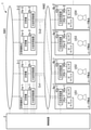
- FIG. 1 is a diagram showing an example of the overall configuration of the information processing system according to the present embodiment.
- the information processing system 1 includes a control device 2, a computer base 3 (3-1, 3-2, ..., 3-n (n is an integer of 1 or more)), and a user base 4 (4a-1).
- 4, 4b-1, 4a-2, 4b-2, ..., 4am (m is an integer of 1 or more), 4bm), a first network NW1, and a second network NW2 (network) are provided.
- one or a plurality of computers 31 and a UI transmission / reception device 32 are installed.
- a computer 31 31an, 31bn, ...)
- a UI transmission / reception device 32 32an, 32bn, ...)
- First transmission / reception device are installed at the computer base 3. Will be done.
- the computer 31 and the UI transmission / reception device 32 may be integrated.
- a part of the configuration installed in the computer base 3 is omitted.
- the configuration installed at the computer base 3 will be described with reference to FIG. 2 and the like.
- the user base 4 includes a UI device 41 (41a-m, 41b-m, ...), a sensor 42 (42a-m, 42b-m, ...), and a UI transmission / reception device 43 (43a-m, 43b-m, ). (Second transmission / reception device) is provided.
- the information processing system 1 has one or more computer bases 3.
- the control device 2 controls the connection relationship between the UI transmission / reception device 43 of the user base 4 and the UI transmission / reception device 32 of the computer base 3.
- the control device 2 is connected to the computer 31 of the computer base 3, the UI transmission / reception device 32, the communication device (not shown) constituting the second network NW2, and the UI transmission / reception device 43 of the user base 4, and confirms the setting information of each device. It is possible to change the settings. Further, the control device 2 performs delay adjustment control.
- the control device 2 is connected to each of the computer base 3, the user base 4, the first network NW1, and the second network NW2 by wire or wirelessly.
- the control device 2 is configured by using a processor such as a CPU (Central Processing Unit) and a memory. In addition, all or a part of each function of the control device 2 may be realized by using hardware such as ASIC (Application Specific Integrated Circuit), PLD (Programmable Logic Device), FPGA (Field Programmable Gate Array).
- ASIC Application Specific Integrated Circuit
- PLD Programmable Logic Device
- FPGA Field Programmable Gate Array
- the above program may be recorded on a computer-readable recording medium.
- Computer-readable recording media include, for example, flexible disks, magneto-optical disks, ROMs, CD-ROMs, portable media such as semiconductor storage devices (for example, SSD: Solid State Drive), hard disks and semiconductor storage built in computer systems. It is a storage device such as a device.
- the above program may be transmitted over a telecommunication line.
- the first network NW1 includes, for example, the Internet and includes a communication network. Further, the first network NW1 may have an authentication function.
- the second network NW2 may be a wired network or a wireless network, and the physical topology and the logical topology may be arbitrary, and may be a circuit-switched network or a packet-switched network.
- the computer base 3 is, for example, a data center, a communication building, a server room, or the like.
- the computer 31 may be a physical computer or a logical computer (virtual computer). In the case of a virtual computer, for example, a CPU, GPU (Graphics Processing Unit), memory, storage, and the like are virtualized. Further, the computer 31 may be a game device.
- the computer 31 is connected to a server (not shown) of another computer or data center via the first network NW1.
- the computer 31 is connected to the UI transmission / reception device 32, and user interface information such as a display signal and operation information of the computer 31 is exchanged.
- Specific examples of the display signal include HDMI (registered trademark, High-Definition Multimedia Interface), DisplayPort, and the like, and the operation information signal includes USB (Universal Serial Bus).
- examples of the signal obtained by combining the display signal and the operation information include USB4 and Thunderbolt (registered trademark) 3.
- one user may use a plurality of physical GPUs in cooperation with each other to boost the boost.
- the UI transmission / reception device 32 receives display signals and operation information, and converts them into a signal format capable of long-distance communication via the second network NW2. Further, the UI transmission / reception device 32 is connected to the UI transmission / reception device 43 of the user base 4 via the second network NW2.
- the signal formats capable of long-distance communication are, for example, Ethernet (registered trademark) and OTN (Optical Transport Network). A configuration example of the UI transmission / reception device 32 will be described later.
- the user base 4 is a base where the user US (US1, 7) Performs work, games, and the like, and is, for example, a home, a company, a business rental space, a game center, and the like.
- the UI device 41 is a device related to a user interface, and is, for example, a display, a keyboard, a mouse, an operation controller (actor), a camera, a VR (virtual reality) headset, an AR (augmented reality) headset, a microphone, a speaker, or the like. be.
- the UI device 41 may be any device that inputs / outputs the five human senses (tactile sense, visual sense, auditory sense, smell sense, taste sense) to and from the computer 31 in addition to the above.
- the UI device 41 and the UI transmission / reception device 43 are connected in a signal format such as HDMI, DisplayPort, or USB.
- the sensor 42 is, for example, a sensor for detecting the movement of the user's hand, face, body, etc., a position sensor, an altitude sensor, a speed sensor, an acceleration sensor, a temperature sensor, a humidity sensor, a pressure sensor, a vibration sensor, an optical sensor, and a sound sensor. , Electric field sensor, magnetic field sensor, etc.
- the sensor 42 and the UI transmission / reception device 43 are connected in a signal format such as USB.
- the UI transmission / reception device 43 is connected to the UI transmission / reception device 32 of the computer base 3 via the second network NW2.
- the second network NW2 is provided with a switching function, and the connection relationship between the UI transmission / reception device 32 of the computer base 3 and the UI transmission / reception device 43 of the user base 4 can be flexibly changed.
- a plurality of UI signals may be multiplexed on the output of the UI transmission / reception device 43. It is sufficient that at least one of the UI device 41 and the sensor 32 is connected to the UI transmission / reception device 43.
- connection between the user base 4 and the computer base 3 will be described.
- two users US1 and US2 are using the computer 31 via the second network NW2.
- the UI transmission / reception device 43a-1 of the user base 4a-1 and the UI transmission / reception device 32b-1 of the computer base 3-1 are connected via the second network NW2.
- the UI transmission / reception device 43b-1 of the user base 4b-1 and the UI transmission / reception device 32b-2 of the computer base 3-2 are connected via the second network NW2.
- the control device 2 controls the connection relationship between the UI transmission / reception devices (32, 43).
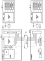
- FIG. 2 is a diagram showing a configuration example of a computer base and an example of a second network according to the present embodiment.
- the computer base 3 (3-1, 3-2) has, for example, at least one computer 31 (31a-1, 31b-2, 31a-2, 31b-2) and at least one computer 31 (31a-1, 31b-2, 31a-2, 31b-2).
- the UI transmission / reception device 32 (32a-1, 32b-2, 32a-2, 32b-2), the allocation device 33 (33-1, 33-2), and the switching device 34 (34-1, 34-2) is set up.
- the UI transmission / reception device 43 of each user base 4 is connected to the switching device 34 of the computer base 3 via the transmission line Tm.
- the transmission line Tm may be, for example, a colored IF (interface) based on a wavelength division multiplexing (WDM) signal or a gray IF based on a non-WDM signal.
- the switching device 34 is also connected to the switching device 34 of another computer base 3 via the transmission line Tm, and the connection relationship between the UI transmission / reception devices (32, 43) can be flexibly changed.
- the switching device 34 is connected to the allocation device 33 of the same computer base 3, and it is possible to set which computer 31 of the computer base 3 to connect to.
- the switching device 34 switches the transmission line Tm according to the control of the control device 2.
- the switching device 34 is, for example, an optical switch, an electric switch, or a robot panel switch.
- the allocation device 33 switches the UI transmission / reception device 32 connected to the UI transmission / reception device 43 of the user base 4 according to the control of the control device 2.
- the assigning device 33 is, for example, an optical switch, an electric switch, or a robot panel switch.
- the UI transmission / reception device 43a-1 of the user base 4a-1 like the route Cn11 based on the control of the control device 2.
- the UI transmission / reception device 32b-1 of the computer base 3-1 via the transmission line Tm-1, the switching device 34-1 of the computer base 3-1 and the allocation device 33-1.
- the UI transmission / reception device 43b-1 of the user base 4b-1 like the path Cn12, based on the control of the control device 2, the transmission path.
- UI transmission / reception device 32b of computer base 3-2 via switching device 34-1 of Tm-2 and computer base 3-1 and switching device 34-2 of transmission line Tm and computer base 3-2 and allocation device 33-2. Connected to -1.
- the second network NW2 is a network having a circuit-switched function (hereinafter referred to as "circuit-switched network").
- Circuit-switched networks are, for example, OTN (Optical Transport Network) and SDH (Synchronous Digital Hierarchy).
- the circuit-switched network includes transmission lines Tm, Tm-1, Tm-2, Tm-11, Tm-12, Tm-21 and the like.
- UI information is exchanged by a network using an Ethernet switch or a router, so MAC (Media Access Control address) frame switching and IP ((Internet Protocol) packets) can be performed anywhere in the network. Was being switched.
- MAC Media Access Control address
- IP Internet Protocol
- the communication capacity can be occupied by one user and the delay time is constant, the communication between the UI transmission / reception device 32 and the UI transmission / reception device 43 is stable.
- One user can occupy the communication capacity by allocating a communication time slot by time division multiplexing.
- the delay time is constant because the assigned time slots are regularly and without delay during switching.
- the circuit-switched network also includes a packet-switched network that emulates circuit-switched.
- a packet-switched network that emulates circuit switching bandwidth is secured by giving priority to packets, and switching delay time is stabilized by switching preferentially according to packet priority during switching. Aim for conversion.
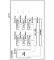
- FIG. 3 is a diagram showing an example of the configuration of the UI transmission / reception device according to the present embodiment.
- the UI transmission / reception device 32 and the UI transmission / reception device 43 have the same configuration will be described, but the configurations may be different.
- the UI transmission / reception device 32 may be, for example, a monitoring control unit 301, at least one UI input / output unit 302 (302a, ...), At least one sensor input / output unit 307 (307a, ...), or compression / decompression. It includes a unit 303 (303a, 303b, ...), At least one mapping / demapping unit 304 (304a, 304b, ...), a multiplexing / separating unit 305, and a transmission / reception unit 306.
- the UI transmission / reception device 43 may be, for example, a monitoring control unit 401, at least one UI input / output unit 402 (402a, ...), At least one sensor input / output unit 407 (407a, ...), or a compression / decompression unit 403 (403a). , 403b, ...), At least one mapping / demapping unit 404 (404a, 404b, ...), a multiplexing / separating unit 405, and a transmission / reception unit 406.
- the configuration shown in FIG. 3 is an example and is not limited to this.
- the monitoring control unit 301 is connected to the control device 2 by a wired or wireless line
- the transmission / reception unit 306 is connected to the allocation device 33
- the UI input / output unit 302 and the sensor input / output unit 307 are computers. Connected to 31.
- the monitoring control unit 401 is connected to the control device 2 by a wired or wireless line
- the transmission / reception unit 406 is connected to the transmission line Tm
- the UI input / output unit 402a is connected to the UI device 41
- the sensor is connected to the sensor 42.
- the arrangement of the transmission / reception unit 406 and the multiplexing / separation unit 405 may be reversed.
- the monitoring control unit 301 is connected to each unit of the UI transmission / reception device 32, and monitors the state of each unit and changes the settings.
- the monitoring control unit 301 is connected to the control device 2 to change the connection relationship of the UI transmission / reception device 32, monitor the status of the UI device 41, and set the operation.
- the monitoring control unit 401 is connected to each unit of the UI transmission / reception device 43, and monitors the state of each unit and changes the settings.
- the monitoring control unit 401 is connected to the control device 2 to change the connection relationship of the UI transmission / reception device 43, monitor the status of the UI device 41, and set the operation.
- the UI input / output unit 302 is connected to the UI signal from the computer 31 in the case of the computer base 3.
- the UI signal is, for example, HDMI, DisplayPort, USB, Thunderbolt, Bluetooth®, analog audio, and digital audio signals.
- the UI input / output unit 302 is connected to the compression / decompression unit 303a.
- the UI input / output unit 402 is connected to the UI device 41.
- the UI input / output unit 402 is connected to the compression / decompression unit 403a.
- the sensor input / output unit 307 is connected to the UI signal from the computer 31.
- the sensor input / output unit 307 is connected to the compression / decompression unit 303b.
- the sensor input / output unit 407 is connected to the sensor 42.
- the sensor input / output unit 407 is connected to the compression / decompression unit 403b.
- the compression / decompression unit 303 compresses or decompresses the capacity of the compressible UI signal according to the control of the monitoring control unit 401. Specific examples include HDMI of display signals and compression of DisplayPort signals. Examples of compression methods include DSC (Display Stream Compression) and VDC-M (VESA Display Compression for) defined by VESA (Video Electronics Standards Association). Mobile), MPEG (Moving Picture Experts Group), etc.
- the compression / decompression unit 303 may be omitted. Further, the compression / decompression unit 303 may change the compression method or the decompression method according to the state of the transmission line Tm. For example, the latency of the compression / decompression unit 303 increases as the compression rate increases. Therefore, the compression / decompression unit 303 uses, for example, a compression method of no compression or a high compression rate in order to realize low latency.
- the compression / decompression unit 303 is connected to the mapping / demapping unit 304.
- the compression / decompression unit 403 performs the reverse processing of the compression / decompression unit 303 according to the control of the monitoring control unit 401.
- the compression / decompression unit 403 is connected to the mapping / demapping unit 404.
- the mapping / demapping unit 304 converts the UI signal into a signal form capable of long-distance transmission according to the control of the monitoring control unit 301.
- the signal form is, for example, OTN defined by ITU-T.
- the mapping / demapping unit 304 is connected to the multiplexing / separating unit 305.
- the mapping / demapping unit 404 converts the UI signal into a signal form capable of long-distance transmission according to the control of the monitoring control unit 401.
- the mapping / demapping unit 404 is connected to the multiplexing / separating unit 405.
- the multiplexing / separating unit 305 multiplexes and separates a plurality of signals according to the control of the monitoring control unit 301.
- OTN Optical Data Unit
- the multiplexing / separating unit 305 multiplexes a plurality of ODU (Optical Data Unit) signals output from the mapping / demapping unit 304 and multiplexes them into a larger capacity ODU. do.
- the multiplexing / separating unit 305 is connected to the transmitting / receiving unit 306.
- the multiplexing / separating unit 305 performs the reverse processing of the multiplexing / separating unit 305 according to the control of the monitoring control unit 401.
- the multiplexing / separating unit 405 is connected to the transmitting / receiving unit 406.
- the transmission / reception unit 306 transmits / receives a signal to be transmitted to the second network NW2 according to the control of the monitoring control unit 301.
- the transmission / reception unit 306 transmits / receives an OTU (Optical Transport Unit) signal.
- the transmission / reception unit 306 is connected to the second network NW2 and is connected to the UI transmission / reception device 43 of the user base 4 via the allocation device 33, the switching device 34, and the transmission line Tm.
- the information capacity to be transmitted and received is, for example, OTU0LL, OTU1, OTU2, OTU2e, OTU3, OTU4, OTUCn, GbE (Gigabit Ethernet), 2.5GbE, 5GbE, 10GbE, 25GbE, 50GbE, 100GbE, 400GbE and the like.
- the transmission / reception unit 306 may change the capacity according to the state of the transmission line Tm.
- the transmission / reception unit 406 transmits / receives information to / from the computer base 3 via the transmission line Tm under the control of the monitoring control unit 401.
- FIG. 4 is a sequence diagram of a processing procedure example of the computer system according to the present embodiment.
- the first user US1 of the user base 4a-1 selects or inputs a request for using the computer 31 by operating, for example, a UI device.
- the UI transmission / reception device 43a-1 of the user base 4a-1 transmits a computer use request to the control device 2 (step S1).
- the control device 2 acquires the computer use request transmitted by the UI transmission / reception device 43a-1 (step S2).
- the computer use request may include the performance of the computer to be used (including the performance of the graphic board).
- the control device 2 selects, for example, the computer 31b-1 of the computer base 3-1 closest to the user base 4a-1 in order to shorten the transmission delay time. If there is no usable computer 31 at the computer base 3, the control device 2 may sequentially search for a plurality of computer bases 3 close to the user base 4 (step S3).
- the control device 2 allocates the UI transmission / reception device 43a-1 to the switching device 34-1 of the computer base 3-1 so as to connect the UI transmission / reception device 43a-1 to the UI transmission / reception device 32b-1 of the computer base 3-1 in the connection relationship of the path Cn11.
- the device 33-1 is controlled (step S4).
- the switching device 34-1 and the assigning device 33-1 of the computer base 3-1 switch the transmission line Tm-1 to be connected according to the control of the control device 2, assign the UI transmitting / receiving device 32b-1, and assign the UI transmitting / receiving device 32b-1.
- the 43a-1 and the UI transmission / reception device 32b-1 are connected (step S5).
- the UI transmission / reception device 43a-1 is connected by the connection relationship of the route Cn11, so that the first user US1 can use the computer 31b-1 of the computer base 3-1 from the user base 4a-1.
- the second user US2 of the user base 4b-1 selects or inputs a request for using the computer 31 by operating, for example, a UI device.
- the UI transmission / reception device 43b-1 of the user base 4b-1 transmits a computer use request to the control device 2 (step S6).
- the control device 2 acquires the computer use request transmitted by the UI transmission / reception device 43b-1 (step S7).
- the control device 2 selects an unused computer 31 based on the computer use request. For example, when the computer 31 of the computer base 3-1 closest to the user base 4b-1 is in use, the control device 2 selects the computer 31b-2 of the computer base 3-2 close to the computer base 3-1. (Step S8).
- the control device 2 is connected to the switching device 34-1 of the computer base 3-1 so as to connect the UI transmission / reception device 43b-1 to the UI transmission / reception device 32b-2 of the computer base 3-2 in the connection relationship of the path Cn12.
- the switching device 34-2 and the allocation device 33-2 of the computer base 3-2 are controlled (step S9).
- the switching device 34-1 of the computer base 3-1 switches so as to connect the transmission lines Tm-2 and Tm to be connected according to the control of the control device 2 (step S10).
- the switching device 34-2 and the allocation device 33-2 of the computer base 3-2 are switched so as to connect the transmission lines Tm-2 and Tm according to the control of the control device 2, and the UI transmission / reception device 32b-2 is assigned.
- the UI transmission / reception device 43b-1 and the UI transmission / reception device 32b-2 are connected (step S11).
- the UI transmission / reception device 43b-1 is connected by the connection relationship of the route Cn12, so that the second user US2 can use the computer 31b-2 of the computer base 3-2 from the user base 4b-1. ..
- the UI device 41 and the sensor 42 of the user base 4 are connected to the computer 31 of the computer base 3 via the second network NW2.
- the control device 2 adjusts the delay time.
- fairness is realized in gaming and eSports, and it is possible for the sensor to acquire sensing information at a plurality of points at the same time.
- the UI device and the computer are installed in physically separated places, the connection relationship can be flexibly changed, and the operation is comparable to that when the UI device and the computer are locally present. A feeling can be realized.
- connection relationship between the UI transmission / reception device 32 and the UI transmission / reception device 43 is determined in consideration of the response time of the UI device 41 that affects the user's operation feeling among the UI devices 41 used by the user. ..
- FIG. 5 is a diagram showing an example of the overall configuration of the information processing system according to the present embodiment.
- the information processing system 1X includes a control device 2, a computer base 3X (3X-1, 3X-2, ..., 3X-n), and a user base 4X (4X-1, 4X-2, 4X-3). 4, X-4, ..., 4X-m), a first network NW1 and a second network NW2.
- a computer 31 (31an, 31bn, ...) And a UI transmission / reception device 32X (32Xa-n, 32Xbn, ...) (First transmission / reception device) are installed at the computer base 3X.
- the computer base 3X is shown by omitting a part of the configuration.
- the user base 4X includes a UI device 41 (41a-m, 41b-m, ...), a sensor 42 (42a-m, 42b-m, ...), and a UI transmission / reception device 43X (43Xa-m, 43Xb-m, . ) (Second transmitter / receiver) is installed.
- the information processing system 1X has one or more computer bases 3X.
- control device 2X has the UI transmission / reception device 43X of the user base 4X and the UI transmission / reception device of the computer base 3X based on the delay time between the UI transmission / reception device 32X and the UI transmission / reception device 43X. Controls the connection relationship with 32X.
- the delay time related to the operation feeling will be described.
- the display device connected to the UI transmission / reception device 43 of the user base 4 has a refresh rate of 60 (Hz)
- the update cycle of the display device is 16.7 (ms).
- you have a keyboard, a calculator, and a display device at hand and the user inputs characters from a keyboard to which the keyboard or display device is directly connected to the computer, the characters entered by the user will be reflected on the screen in the next cycle. Will be done.
- the user's operation is reflected on the screen with a delay of at least 6 frames added, and the operation feeling deteriorates.
- the connection relationship of the UI transmission / reception device is defined so that the control device 2X is within a predetermined delay time. ..
- the predetermined delay time may be, for example, a delay time desired by the user.
- the control device 2X selects and connects the UI transmission / reception device 32X of the computer base 3X so that the round trip time is within a predetermined time desired by the user.
- the control device 2X is a UI transmission / reception device of the computer base 3X based on a predetermined round trip time and a delay time desired by the user. Select 32X and connect.
- control device 2X is the UI transmitter / receiver 32X of the computer base 3X so that the round trip time between the UI transmitters / receivers is 1 / f (sec) or less when the update frequency of the UI device 41 is f (Hz). You may select to connect.
- the UI transmission / reception device can be selected by displaying the delay time table between the bases of the control device 2X on the display device and selecting by operating the UI device, or the delay time from the distance of the transmission line connecting the bases.
- FIG. 6 is a diagram showing an example of the configuration of the UI transmission / reception device according to the present embodiment.
- the UI transmission / reception device 32X of the computer base 3X is, for example, a monitoring control unit 301X, at least one UI input / output unit 302 (302a, ...) Or a sensor input / output unit 307 (307a, ...), At least 1.
- It includes one compression / decompression unit 303 (303a, 303b, ...), At least one mapping / demapping unit 304 (304a, 304b, ...), a multiplexing / separation unit 305, a transmission / reception unit 306, and a delay measurement unit 308.
- the delay measuring unit 308 may be located between the mapping / demapping unit 304 and the multiplexing / separating unit 305.
- the configuration shown in FIG. 6 is an example and is not limited to this.
- the UI transmission / reception device 43X of the user base 4X is, for example, a monitoring control unit 401X, at least one UI input / output unit 402 (402a, ...) or a sensor input / output unit 407 (407a, ...), And at least one compression / decompression. It includes a unit 403 (403a, 403b, ...), At least one mapping / demapping unit 404 (404a, 304b, ...), a multiplexing / separating unit 405, a transmission / reception unit 406, and a delay measuring unit 408.
- the delay measuring unit 408 may be located between the mapping / demapping unit 404 and the multiplexing / separating unit 405. In FIG. 6, a part of the configuration of the UI transmission / reception device 43X is omitted.
- the UI transmission / reception device 32X (43X) of the present embodiment further includes a delay measurement unit 308 (408) in addition to the UI transmission / reception device 32 (43) of the first embodiment.
- the delay measuring unit 308 (408) measures the delay between the delay measuring unit and the delay measuring unit of the opposite UI transmission / reception device.
- the delay measuring method is, for example, ODU Delivery Measurement (ODU DM) defined by OTN.
- the monitoring control unit 301X acquires the delay time measured by the delay measuring unit 308 (408). At least one of the monitoring control unit 301X and the monitoring control unit 401X outputs the acquired delay time information indicating the delay time to the control device 2X.
- the control device 2X determines the connection relationship between the UI transmission / reception device 32 and the UI transmission / reception device 43 based on the delay time acquired from the plurality of UI transmission / reception devices 33X (or 44X).
- FIG. 7 is a sequence diagram of a processing procedure example of the computer system according to the present embodiment.
- the user operates the UI device 41 of the user base 4X and inputs a desired land trip time.
- the UI transmission / reception device 43X transmits a desired land trip time to the control device 2X (step S51).
- the control device 2X acquires the desired land trip time of the UI transmission / reception device 4 (step S52).
- the control device 2X transmits a delay time measurement instruction to the UI transmission / reception device 32X of the computer base 3X (step S53).
- the UI transmission / reception device 32X acquires the measurement instruction of the delay time (step S54).
- the control device 2X instructs the switching device 34 and the assigning device 33 of the computer base 3 to temporarily connect the UI transmission / reception device 43 to the UI transmission / reception device 32X of the computer base 3X for measuring the delay time (step). S55).
- the switching device 34 and the allocation device 33 of the computer base 3X are switched so as to temporarily connect the transmission lines to be connected according to the instruction of the control device 2X, and the UI transmission / reception device 32X is temporarily assigned to the UI transmission / reception device 43X and the UI.
- Temporarily connect the transmitter / receiver 32X (step S56).
- the UI transmission / reception device 32X measures the delay time between the UI transmission / reception device 32X and the UI transmission / reception device 43X of the user base 4X, and transmits the measured measurement result to the control device 2X (step S57).
- the control device 2X acquires the measurement result (step S58).
- the control device 2X selects a computer 31 to be connected to the UI transmission / reception device 43X of the user base 4X based on the delay time which is the acquired measurement result (step S59).
- the control device 2X controls the switching device 34 of the computer base 3 and the allocation device 33 so as to connect the UI transmission / reception device 43 to the UI transmission / reception device 32X of the selected computer base 3X (step S60).
- the switching device 34 and the allocation device 33 of the computer base 3X are switched so as to connect the transmission lines to be connected according to the control of the control device 2X, the UI transmission / reception device 32X is assigned, and the UI transmission / reception device 43X and the UI transmission / reception device 32X. (Step S61).
- control device 2X may acquire and store the delay time in advance for each combination of the UI transmission / reception device 43X of the user base 4X and the UI transmission / reception device 32X of the computer base 3X.
- the control device 2X is, for example, a user base 4Xb-1 based on the first combination delay time.
- the computer 31 to be connected to the UI transmission / reception device 43Xb-1 may be selected.
- the control device 2X selects, for example, a plurality of combinations of the UI transmission / reception device 43Xb-1 of the user base 4Xb-1 and the UI transmission / reception device 32Xb-2 of the computer base 3X-2, which are equivalent to the acquired delay time. You may.
- the UI transmission / reception device 43Xa-1 of the user base 4Xa-1 and the UI transmission / reception device 32Xb-1 of the computer base 3X-1 for example, the UI transmission / reception device 43Xb-1 of the user base 4Xb-1.
- the target to be connected to may be selected from another UI transmission / reception device 32Xa-1 of the same computer base 3X-1 without measuring the delay amount. The reason for this is that if the computers are connected to the UI transmission / reception device in the same computer base 3X, it can be considered that the delay amounts are almost the same.
- the UI device 41 and the sensor 42 of the user base 4 are connected to the computer 31 of the computer base 3 via the second network NW2 in consideration of the delay time.
- the UI device 41 and the sensor 42 of the user base 4 are connected to the computer 31 of the computer base 3 via the second network NW2 in consideration of the delay time.
- the UI device and the computer are installed in physically separated places, the connection relationship can be flexibly changed, and the operation feeling is comparable to that when the UI device and the computer are locally present. Can be realized.
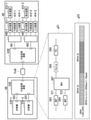
- FIG. 8 is a diagram showing a specific first configuration example of the information processing system.
- a graphic board including GPU 321) is mounted on the computer 31A installed in the computer base 3A, and DisplayPort is output as a video signal.
- the graphic board may be equipped with a plurality of terminals, and for example, as shown in FIG. 8, two DisplayPort signal lines 351 and 352 may be used at the same time.
- a plurality of graphic boards may be mounted on one computer, and a plurality of terminals may be used by one user or a plurality of users.
- the computer 31A exchanges operation information and the like with a USB (for example, USB2.0 or USB3.2) terminal via signal lines 353 and 354.
- USB for example, USB2.0 or USB3.2
- the UI transmission / reception device 32A of the computer base 3A and the UI transmission / reception device 43A of the user base 4A are connected to, for example, the I / O (input / output port) 311 of the QSFP28 standard via the transmission line TmA.
- the function of the UI transmitter / receiver 32A is implemented in, for example, an ASIC (Application Specific Integrated Circuit) or an FPGA (Field Programmable Gate Array).
- FIG. 8 shows an example in which an FPGA is used in the UI transmission / reception device 32A to accommodate and multiplex various signals in the OTN.
- the signal transmitted from the UI transmission / reception device 32A is transmitted through the optical fiber transmission line TmA and sent to the UI transmission / reception device 43A of the user base 4A.
- the transmission line TmA may be bidirectional with one core or bidirectional with two cores. Further, the transmission line may be different depending on the transmission direction.
- the downlink transmission line is a passive optical network PON (Passive Optical Network)
- the uplink is a transmission line of a 4th generation communication standard or a 5th generation communication standard. You may.
- the UI transmission / reception device 43A restores the original signal by the reverse processing of the transmission side.
- the restored signals here DisplayPort 451 and 452, USB3.0 (413), and USB2.0 (414) signals are output from the UI transmission / reception device 43A, and are output from the UI transmission / reception device 43A to display device 411, display device 412, external device 413, and input device. Connected to 414.
- Examples of the external device 413 which is a USB device and the input device 414 which is a USB device include input / output devices such as a keyboard, a mouse, and a gaming controller, a large-capacity storage device, an audio interface, a camera, and various sensors.
- the device connected to the UI transmission / reception device 43A is not limited to this. Also in the following configuration example, the device connected to the UI transmission / reception device at the user base is not limited to this.
- Comp is an abbreviation for Compression
- MAP is an abbreviation for Mapping
- MUX is an abbreviation for Multiplexing
- Encrip is an abbreviation for Encryption
- FEC is an abbreviation. It is an abbreviation for Forward Error Correction.
- the FPGA implements the OTN function as shown in the implementation example g11. Various things can be considered for the resolution, refresh rate, and color depth of the video signal.
- This signal is compressed by the compression / decompression unit (Comp) 303 (303a, 303b) as needed.
- the compression is performed by, for example, VESA DSC.
- VESA DSC When VESA DSC is used, 3: 1 compression is performed and the bit rate can be reduced to about 8.7 (Gbps).
- compression is not performed, there is an advantage of low latency because the compression process does not take time, but on the other hand, the transfer capacity becomes large.
- the latency is higher than in the case of non-compression because the compression process takes time, but on the other hand, there is an advantage that the transfer capacity can be reduced.
- the bit rate of the image is, for example, 1.67 (Gbps) in the case of 1080p 240 (Hz) DSC and 8.61 (Gbps) in the case of 4K 120 (Hz) 24 (bpp) DSC.
- the case of 8K 60 (Hz) 24 (bpp) is 49.65 (Gbps).
- the DisplayPort signal is accommodated in the ODU frame by the mapping function of OTN (MAP363-366).
- the mapping / demapping unit 304 has a mapping function.
- mapping for example, BMP (Bit-synchronous Mapping Procedure), AMP (Asynchronous Mapping Procedure), and GMP (Generic Mapping Procedure) defined by OTN can be applied.
- the signal accommodated in the ODU is multiplexed in the upper ODU frame by the multiplexing function (MUX367) of the OTN.
- the multiplexing function MUX367
- the size of the tributary slot of ODU4 is 1.302 (Gbps), so that the tributary slot is 20 tributary slots, that is, ODTU4.20. It is possible to multiplex.
- the multiplex step of MAP363 to 365 and MUX367 is ODUflex (371 to 373)
- the multiplex step of MAP366 and MUX367 is ODU0 (374).
- the multiplex step of MUX367 and Encryp368, the multiplex step of Encryp368 and FEC369, and the multiplex step of FEC377 and I / O311 of the QSFP28 standard are ODU4 (375, 376, 377).
- the Encrip 368 performs encryption processing.
- FEC369 performs erroneous correction code processing.
- USB3.0 signal a USB3.0 signal and a USB2.0 signal are shown.
- the bit rate of the USB3.0 signal is 5 (Gbps), and the bit rate of the USB2.0 signal is 480 (Mbps).
- the USB signals are first accommodated in the ODU frame by the mapping function of the OTN, and then multiplexed in the required number of tributary slots in the upper ODU frame.
- the USB3.0 signal can be multiplexed in 4 tributary slots
- the USB2.0 signal can be multiplexed in 1 tributary slot.
- An example of the usage status of the tributary slot of ODU4 is shown in the area surrounded by the reference numeral g12 in FIG. As long as the tributary slot is free, it is possible to multiplex signals other than those shown here. After being multiplexed, it is encrypted as necessary, and then an error correction code (FEC) is added to the ODU, and the signal is output from the UI transmitter / receiver as an OTU4 signal.
- FEC error correction code
- To send and receive OTU4 signals from the UI transmitter / receiver 32A for example, a QSFP28 standard 100G optical module or an electric cable (DAC; Direct Attachment Cable) having a QSFP28 connector at both ends can be used.
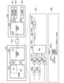
- FIG. 9 is a diagram showing a specific second configuration example of the information processing system.
- the signal line 355 of the computer 31B (31B-1, 31B-2) of the computer base 3B is a signal line for transmitting a Thunderbolt 3 standard signal.
- the computer 31B and the UI transmission / reception device 32B are connected by the signal line 355.
- the Thunderbolt 3 is a signal in which a video signal, a USB signal, and the like are multiplexed, both the video signal and the USB signal can be transmitted and received only by transferring the Thunderbolt 3.
- the Thunderbolt 3 signal is accommodated in the ODU frame, then multiplexed with the upper ODU, and transmitted from the UI transmission / reception device 32B to the user base 4B.
- the UI transmission / reception device 32B is connected to a plurality of computers 31B (31B-1, 31B-2), and signals from those computers 31B may be multiplexed and transmitted.
- the transmission line TmB between the computer base 3B and the user base 4B is, for example, OTU4 or OTL4.4.
- the UI transmission / reception device 43B of the user base 4B is connected to the Thunderbolt 3 dock 44B (44B-1, 44B-2).
- Thunderbolt 3 dock44B separates the multiplexed signal.
- the Thunderbolt 3 dock44B has one or more display devices 411 (411-1, 411-2), 412 (412-1, 412-2), and external devices 413 (413-1, 413-1, USB 3.0 devices). 413-2), an input device 414 (414-1, 414-2) such as a keyboard and a mouse is connected.
- FIG. 10 is a diagram showing a specific third configuration example of the information processing system.
- two DisplayPort signals are input / output from the computer 31C of the computer base 3C via the signal lines 351 and 352, and one USB 2.0 signal is input / output via the signal line 354. Will be done.
- These signals are input to the UI transmission / reception device 32C.
- the case where the video signal is 1080p, 60 (fps), 24 (bpp) is shown. In that case, the bit rate of the video signal is about 3.2 (Gbps).
- USB 2.0 is 480 (Mbps).
- Each ODU signal is multiplexed with a higher ODU.
- the ODU2 signal is used as the upper ODU.
- the capacity of the tributary slot of ODU2 is 1.249 (Gbps), and the ODU to which each signal is mapped is multiplexed into the required number of tributary slots as in the region surrounded by the reference numeral g32 in FIG.
- the housed ODU of DisplayPort is multiplexed into 3 tributary slots, i.e., ODTU2.3.
- the housed ODU of USB 2.0 is multiplexed in one tributary slot, that is, ODTU 2.1.
- the UI transmission / reception device 32C encrypts the ODU2 signal as necessary, assigns an error correction code, and then uses 10 (Gbps) as an OTU2 signal, for example, called SFP +. It is transmitted from the optical module 311C of.
- the transmission line TmC between the computer base 3C and the user base 4C is, for example, OTU2 (LR).
- the transmission line TmC may be bidirectional with one core or bidirectional with two cores.
- the original signal is restored by the reverse processing of the transmission side.
- the restored signal in this case the DisplayPort 451 and 452, and the USB 2.0 (454) signal, is output from the UI transmission / reception device 43C and is connected to the display device 411, 412 or the USB 2.0 device such as the input device 414. ..
- FIG. 11 is a diagram showing a specific fourth configuration example of the information processing system.
- a plurality of computers 31D 31D-1, 31D-2, 31D-3, ...)
- a plurality of UI transmission / reception devices 32D 32D-1, 32D-2, 32D-3, ...) are located in the computer base 3D. ) Is installed.
- the performances of the graphic boards GPU321D (321D-1, 321D-2, 321D-3) of the three computers 31D-1, 31D-2, and 31D-3 are different.
- GPU321D-1 is a high-performance graphic board
- GPU321D-2 is a medium-performance graphic board
- GPU321D-3 is a low-performance graphic board.
- each computer 31D is connected to the UI transmission / reception device 32D.
- An optical switch 35D (switch) is connected to the output of the UI transmitter / receiver 32D.
- the optical switch is, for example, a robot patch panel that changes the connection relationship of the optical connector by operating the robot arm.
- the optical switch is connected to each transmission line TmD (TmD-1, TmD-2, TmD-3, ...), And is a UI transmitter / receiver for the user base 4D (4D-1, 4D-2, 4D-3, ). It is connected to 43D (43D-1, 43D-2, 43D-3, ).
- the transmission line TmD is, for example, OTU4 or OTL4.4 (LR4).
- the UI transmission / reception device 43D of the user base 4D is connected to a display device, a USB 3.0 device, for example, an external device, or a USB 2.0 device, for example, an input device, as in the first to third embodiments. There is.
- the connection between the UI transmission / reception device 32D and the UI transmission / reception device 43D is performed by the optical switch 35D according to the control of the control device 2 (or 2X).
- the control device 2 or 2X
- the UI transmitter / receiver 32D and the UI transmitter / receiver 43D are connected by an optical switch according to the control of the control device 2 (or 2X). By changing the connection relationship, it becomes possible to use an appropriate computer 31D.
- FIG. 12 is a diagram showing a specific fifth configuration example of the information processing system.
- the switch 35E is, for example, a DP (display), a USB switch, or the like, and is controlled and switched by the control device 2 (or 2X).
- the optical switch 35D shown in FIG. 11 of the fourth embodiment may be a Thunderbolt 3 switch 35F (switch) as shown in FIG.
- FIG. 13 is a diagram showing a specific sixth configuration example of the information processing system.
- the computer 31F 31Fa-1, 31Fb-1, 31Fa-2, 31Fb-2, 31Fa-3, 31Fb-3, ...)
- the UI transmitter / receiver 32F 32F-1, 32F) of the computer base 3F ) -2, 32F-3, ...)
- a Thunderbolt 3 switch 35F is provided.
- the output port 356 of the computer 31F is, for example, USB Type-C
- the computer 31F and the Thunderbolt 3 switch 35F are connected by a Thunderbolt 3 standard signal line 355 or the like.
- the computer 31F-1 (31Fa-1, 31Fb-1) is a high-performance graphic board
- the computer 31F-2 (31Fa-2, 31Fb-2) is a medium-performance graphic board
- the computer 31F-3 (31Fa-3, 31Fb-3) is a low-performance graphic board.
- Each port of the UI transmission / reception device 43F (43F-1, 43F-2, 43F-3, ...) has a signal line 456. It is connected to the Thunderbolt 3 dock 44F (44Fa-1, 44Fb-1, 44Fa-2, 44Fb-2, 44Fa-3, 44Fb-3, ).
- the Thunderbolt 3 dock 44F switching control is performed by the control device 2 (or 2X). Further, the configurations of the user bases 4F-1, 4F-2, and 4F-3 may be the same or different.
- FIG. 14 is a specific seventh configuration example of the information processing system, and is a diagram showing an example in which a plurality of computer bases are connected to each other.
- the computer base 3G- which is directly connected to the user base 4D-1 by the transmission line. A case where all the computers 31G having the performance required by the user are used by another user and there is no space, or a case where such a computer 31G is not installed will be described.
- the computer 31G having the desired performance by the user is installed at the computer base 3G-2 and can be used.
- the signal from the UI transmission / reception device 43D-1 of the user base 4D-1 is directly connected via the transmission line TmD-1 like the chain line of the path Cn21 according to the control of the control device 2 (or 2X). It is connected to the optical switch 35G-1 of the computer base 3G-1 which is used.
- a signal is sent to the optical transmission device 36Ga-1 for communicating with the computer base 3G-2 in which the computer 31G having the desired performance is installed.
- optical multiplexing is performed by the optical multiplexing device 37G-1 as needed, and a signal reaches the computer base 3G-2.
- signals are separated by the optical multiplexing device 37G-2, the separated signals are input to the optical transmission device 36Ga-2, and the UI transmission / reception device 32G-2 and the UI transmission / reception device 32G-2 are transmitted via the optical fiber switch 35G-2. Be connected.
- the port of the optical transmission device 36G (36Ga-1, 36Gb-1, 36Ga-2, 36Gb-2) connected to the optical switch 35G (35G-1, 35G-2) (switch) is, for example, a QSFP28 standard port. be.
- the port of the optical transmission device 36G (36Ga-1, 36Gb-1, 36Ga-2, 36Gb-2) connected to the optical multiplexing device 37G (37G-1, 37G-2) is, for example, of the QSFP56-DD standard. It is a port.
- the optical switch 35G (35G-1, 35G-2) is, for example, an optical fiber switch, a robot patch panel, or the like.
- the computer bases 3G are connected to each other by a transmission line TmG.
- the transmission line TmG is, for example, an optical fiber cable for transmitting a 400G-ZR (DWDM) or OTU4 standard signal.
- FIG. 15 is a specific eighth configuration example of the information processing system, and is a diagram showing another connection example connecting adjacent computer bases.
- the computer bases 3H (3H-1, 3H-2) are connected by a transmission medium 5H such as a multi-core optical fiber or a multi-core fiber.
- the transmission medium 5H enables connection between the UI transmission / reception device 43D-1 of the user base 4D-1 and the UI transmission / reception device 32H-2 of the computer base 3H-2, for example.
- the transmission medium 5H may be a multi-way path.
- FIG. 16 is a specific ninth configuration example of the information processing system, and is a diagram showing another connection example connecting adjacent computer bases.
- the UI transmission / reception device 43J (43J-1, 43J-2) of the user base 4J (4J-1, 4J-2) is provided with a WDM interface.
- the signal from the UI transmission / reception device 43J is an optical switch of the computer base 3J-1 to which the user base 4J-1 is directly connected via the transmission line TmD (TmD-1, TmD-2). Reach 35J-1.
- the optical switch 35J (35-J, 35J-2) (switch) may be an optical switch, a robot patch switch, or the like. It is switched by the optical switch 35J-1 and input to the optical multiplexing device 37J-1 or ROADM (Reconfigurable Optical Add Drop Multiplexer) for transmission to the adjacent computer base 3J-2, and transmitted to the adjacent computer base 3J-2. Will be done.
- the transmitted signal is separated by the optical multiplexing device 37J-2 or ROADM and connected to the desired UI transmission / reception device 32J-2 via the optical fiber switch 35J-2.
- the UI transmission / reception device 32J (32J-1, 32J-2) of the computer base 3J (3J-1, 3J-2) is connected to the optical switch 35J via, for example, the CFP2 port 312.
- the UI transmission / reception device 43J of the user base 4J is connected to the transmission line TmD (TmD-1, TmD-2) via, for example, the CFP2 port 457.
- the transmission line TmJ is, for example, an optical fiber cable for transmitting an OTU4 (WDM) standard signal.
- the present invention can be applied to, for example, a gaming system, an eSports system, a remote desktop system, a computer rental system, and the like.
- transmission / reception unit 307 ... sensor input / output unit, 308 ... delay measurement unit, 321 ... GPU , 401 ... Monitoring control unit, 402 ... UI input / output unit, 403 ... compression / decompression unit, 404 ... mapping / demapping unit, 405 ... multiplexing / separation unit, 406 ... transmission / reception unit, 407 ... sensor input / output unit, 408 ... Delay measurement unit, NW1 ... 1st network, NW2 ... 2nd network, Tm ... Transmission path
Landscapes
- Engineering & Computer Science (AREA)
- Computer Hardware Design (AREA)
- Theoretical Computer Science (AREA)
- Computer Networks & Wireless Communication (AREA)
- Signal Processing (AREA)
- Software Systems (AREA)
- Physics & Mathematics (AREA)
- General Engineering & Computer Science (AREA)
- General Physics & Mathematics (AREA)
- Computer And Data Communications (AREA)
Priority Applications (3)
| Application Number | Priority Date | Filing Date | Title |
|---|---|---|---|
| PCT/JP2020/034759 WO2022054291A1 (ja) | 2020-09-14 | 2020-09-14 | 情報処理システム、情報処理方法およびプログラム |
| JP2022547374A JP7549254B2 (ja) | 2020-09-14 | 2020-09-14 | 情報処理システム、接続制御方法およびプログラム |
| US18/025,129 US12248428B2 (en) | 2020-09-14 | 2020-09-14 | Information processing system, information processing method and program |
Applications Claiming Priority (1)
| Application Number | Priority Date | Filing Date | Title |
|---|---|---|---|
| PCT/JP2020/034759 WO2022054291A1 (ja) | 2020-09-14 | 2020-09-14 | 情報処理システム、情報処理方法およびプログラム |
Publications (1)
| Publication Number | Publication Date |
|---|---|
| WO2022054291A1 true WO2022054291A1 (ja) | 2022-03-17 |
Family
ID=80631777
Family Applications (1)
| Application Number | Title | Priority Date | Filing Date |
|---|---|---|---|
| PCT/JP2020/034759 Ceased WO2022054291A1 (ja) | 2020-09-14 | 2020-09-14 | 情報処理システム、情報処理方法およびプログラム |
Country Status (3)
| Country | Link |
|---|---|
| US (1) | US12248428B2 (https=) |
| JP (1) | JP7549254B2 (https=) |
| WO (1) | WO2022054291A1 (https=) |
Families Citing this family (2)
| Publication number | Priority date | Publication date | Assignee | Title |
|---|---|---|---|---|
| US12500678B2 (en) * | 2020-09-29 | 2025-12-16 | Ntt, Inc. | Information processing system, delay control device, information processing method and program |
| US12261641B2 (en) * | 2022-11-18 | 2025-03-25 | Cisco Technology, Inc. | Delay measurement for hybrid packet and optical transport networks |
Citations (2)
| Publication number | Priority date | Publication date | Assignee | Title |
|---|---|---|---|---|
| JP2012505561A (ja) * | 2008-10-08 | 2012-03-01 | 日本電気株式会社 | シンクライアントセッションの確立方法 |
| JP2013183203A (ja) * | 2012-02-29 | 2013-09-12 | Nippon Telegr & Teleph Corp <Ntt> | 制御サーバ、制御方法及び制御プログラム |
Family Cites Families (36)
| Publication number | Priority date | Publication date | Assignee | Title |
|---|---|---|---|---|
| JPH10117215A (ja) | 1996-08-22 | 1998-05-06 | Furukawa Electric Co Ltd:The | ネットワーク間接続方法及びその装置 |
| DE19945663A1 (de) | 1999-09-23 | 2001-04-05 | Siemens Ag | Internet-Telefonadapter |
| US6678524B1 (en) | 2000-05-31 | 2004-01-13 | Telefonaktiebolaget Lm Ericsson (Publ) | Bearer selection in a mobile communication system having both circuit-switched and packet-switched bearers |
| JP4095325B2 (ja) | 2002-03-29 | 2008-06-04 | キヤノン株式会社 | 画像配信方法およびその動作処理を実行するプログラムおよびそのプログラムを記憶した記憶媒体、および画像配信装置および画像受信装置 |
| JP4458767B2 (ja) | 2003-04-16 | 2010-04-28 | エボリウム・エス・アー・エス | 携帯電話システム |
| US7246172B2 (en) | 2003-06-06 | 2007-07-17 | Matsushita Electric Industrial Co., Ltd. | Static dense multicast path and bandwidth management |
| JP3937337B2 (ja) | 2003-08-15 | 2007-06-27 | 日本電信電話株式会社 | 配信レート制御方法及びシステム |
| KR20060088939A (ko) | 2005-02-02 | 2006-08-07 | 삼성전자주식회사 | 광 네트워크에서의 광채널 할당시스템 및 그 방법 |
| US20070079307A1 (en) | 2005-09-30 | 2007-04-05 | Puneet Dhawan | Virtual machine based network carriers |
| US7822065B2 (en) | 2007-01-07 | 2010-10-26 | Wei Lu | Open wireless architecture (OWA) medium access control (MAC) processing architecture for future mobile terminal |
| US20080235361A1 (en) | 2007-03-21 | 2008-09-25 | David Crosbie | Management layer method and apparatus for dynamic assignment of users to computer resources |
| JP5164628B2 (ja) * | 2008-03-24 | 2013-03-21 | 株式会社日立製作所 | ネットワークスイッチ装置、サーバシステム及びサーバシステムにおけるサーバ移送方法 |
| TW201007574A (en) | 2008-08-13 | 2010-02-16 | Inventec Corp | Internet server system and method of constructing and starting a virtual machine |
| US20110126197A1 (en) | 2009-11-25 | 2011-05-26 | Novell, Inc. | System and method for controlling cloud and virtualized data centers in an intelligent workload management system |
| US9141420B2 (en) | 2010-11-04 | 2015-09-22 | Alcatel Lucent | Overload control in a cloud computing environment |
| US9785478B1 (en) | 2010-11-12 | 2017-10-10 | Vmware, Inc. | Mass migration of desktop deployments to virtual desktop infrastructures |
| WO2013003327A1 (en) | 2011-06-27 | 2013-01-03 | University Of Massachusetts | Dynamic advance reservation with delayed allocation |
| US9461881B2 (en) | 2011-09-30 | 2016-10-04 | Commvault Systems, Inc. | Migration of existing computing systems to cloud computing sites or virtual machines |
| US8719534B1 (en) * | 2012-03-21 | 2014-05-06 | Netapp, Inc. | Method and system for generating a migration plan |
| KR101384934B1 (ko) | 2012-06-29 | 2014-04-14 | 인텔렉추얼디스커버리 주식회사 | 모바일 노드의 이동을 처리하기 위한 방법 및 장치 |
| EP2687982A1 (en) | 2012-07-16 | 2014-01-22 | NTT DoCoMo, Inc. | Hierarchical system for managing a plurality of virtual machines, method and computer program |
| US20140181984A1 (en) | 2012-12-21 | 2014-06-26 | International Business Machines Corporation | Method and apparatus for authentication of solution topology |
| US9069608B2 (en) | 2013-03-06 | 2015-06-30 | Vmware, Inc. | Method and system for providing a roaming remote desktop |
| EP3041311B1 (en) | 2013-08-26 | 2023-10-04 | Nec Corporation | Communication apparatus and method in communication system, and communication path control apparatus and method |
| JP6001516B2 (ja) | 2013-09-24 | 2016-10-05 | 株式会社日立製作所 | 通信システム及び通信装置 |
| US20150363219A1 (en) | 2014-03-14 | 2015-12-17 | Avni Networks Inc. | Optimization to create a highly scalable virtual netork service/application using commodity hardware |
| US9146769B1 (en) | 2015-04-02 | 2015-09-29 | Shiva Shankar | Systems and methods for copying a source machine to a target virtual machine |
| US20170235737A1 (en) | 2016-02-12 | 2017-08-17 | Nutanix, Inc. | Entity database ranking |
| US10785144B2 (en) | 2016-12-30 | 2020-09-22 | Equinix, Inc. | Latency equalization |
| US11089105B1 (en) | 2017-12-14 | 2021-08-10 | Pure Storage, Inc. | Synchronously replicating datasets in cloud-based storage systems |
| US10929195B2 (en) | 2017-08-07 | 2021-02-23 | Dynavisor, Inc. | Method and system for cloud virtualization |
| US10855537B2 (en) | 2018-04-24 | 2020-12-01 | Vmware, Inc. | Methods and apparatus for template driven infrastructure in virtualized server systems |
| EP3564687B1 (en) * | 2018-05-03 | 2023-02-22 | Siemens Aktiengesellschaft | Determination of power transmission line parameters using asynchronous measurements |
| US11301407B2 (en) | 2019-01-08 | 2022-04-12 | Intel Corporation | Technologies for accelerator fabric protocol multipathing |
| CN111416794B (zh) | 2019-01-08 | 2022-07-29 | 华为技术有限公司 | 一种数据传输方法及电子设备 |
| US11496404B2 (en) * | 2019-06-27 | 2022-11-08 | Google Llc | Congestion control for low latency datacenter networks |
-
2020
- 2020-09-14 US US18/025,129 patent/US12248428B2/en active Active
- 2020-09-14 JP JP2022547374A patent/JP7549254B2/ja active Active
- 2020-09-14 WO PCT/JP2020/034759 patent/WO2022054291A1/ja not_active Ceased
Patent Citations (2)
| Publication number | Priority date | Publication date | Assignee | Title |
|---|---|---|---|---|
| JP2012505561A (ja) * | 2008-10-08 | 2012-03-01 | 日本電気株式会社 | シンクライアントセッションの確立方法 |
| JP2013183203A (ja) * | 2012-02-29 | 2013-09-12 | Nippon Telegr & Teleph Corp <Ntt> | 制御サーバ、制御方法及び制御プログラム |
Also Published As
| Publication number | Publication date |
|---|---|
| JPWO2022054291A1 (https=) | 2022-03-17 |
| US12248428B2 (en) | 2025-03-11 |
| JP7549254B2 (ja) | 2024-09-11 |
| US20240028552A1 (en) | 2024-01-25 |
Similar Documents
| Publication | Publication Date | Title |
|---|---|---|
| JP7620233B2 (ja) | 情報処理システムおよび情報処理方法 | |
| US8670076B2 (en) | Method and system for configuring an asymmetric link based on monitored messages | |
| US9871700B2 (en) | Methods and systems for changing topology of an asymmetric network | |
| US11082739B2 (en) | Data flow control method and apparatus | |
| JP7549254B2 (ja) | 情報処理システム、接続制御方法およびプログラム | |
| US20230362330A1 (en) | Transmission Method, Apparatus, and System | |
| KR20130126932A (ko) | 고속 비디오 네트워크 내의 비동기 및 등시 데이터 송신을 위한 방법 및 시스템 | |
| US12301671B2 (en) | Information processing system, information processing method and program | |
| JP6467822B2 (ja) | 表示システム、送信装置、及び、表示システムの制御方法 | |
| US20150125148A1 (en) | Transmission apparatus | |
| KR20160112571A (ko) | 인터페이스 규격에 상관없는 무선 인터페이스 장치 | |
| KR101579850B1 (ko) | 10GbE 네트워크에서 비압축 HDMI/DVI 영상 패킷화 장치 및 그를 이용한 영상 송수신 방법 | |
| CN113423142B (zh) | 一种无线信号传输方法以及装置 | |
| KR101292782B1 (ko) | Hdmi 신호와 usb 신호를 포함하는 복합신호 전송장치 및 그 방법 | |
| KR20180019857A (ko) | 유에스비 통신 시스템 | |
| CN112911168B (zh) | 数据传输方法及装置 | |
| CN111356037A (zh) | 光传送网线路带宽切换方法及装置 | |
| US20250150551A1 (en) | Information processing system, information processing method and program | |
| WO2025112916A1 (zh) | 一种多通道对齐方法、装置及系统 | |
| JP2016103761A (ja) | 光伝送装置及び光伝送方法 | |
| JP6080705B2 (ja) | 通信装置 | |
| US20170353692A1 (en) | Communication device and communication method | |
| JP2003258755A (ja) | サービス多重化装置およびシステムと方法 | |
| JPH04287589A (ja) | 映像信号多重方式 | |
| JP2006217387A (ja) | 放送ネットワークシステム |
Legal Events
| Date | Code | Title | Description |
|---|---|---|---|
| 121 | Ep: the epo has been informed by wipo that ep was designated in this application |
Ref document number: 20953356 Country of ref document: EP Kind code of ref document: A1 |
|
| ENP | Entry into the national phase |
Ref document number: 2022547374 Country of ref document: JP Kind code of ref document: A |
|
| WWE | Wipo information: entry into national phase |
Ref document number: 18025129 Country of ref document: US |
|
| NENP | Non-entry into the national phase |
Ref country code: DE |
|
| 122 | Ep: pct application non-entry in european phase |
Ref document number: 20953356 Country of ref document: EP Kind code of ref document: A1 |
|
| WWG | Wipo information: grant in national office |
Ref document number: 18025129 Country of ref document: US |