WO2022050116A1 - 光ケーブル及び光ケーブル製造方法 - Google Patents
光ケーブル及び光ケーブル製造方法 Download PDFInfo
- Publication number
- WO2022050116A1 WO2022050116A1 PCT/JP2021/030854 JP2021030854W WO2022050116A1 WO 2022050116 A1 WO2022050116 A1 WO 2022050116A1 JP 2021030854 W JP2021030854 W JP 2021030854W WO 2022050116 A1 WO2022050116 A1 WO 2022050116A1
- Authority
- WO
- WIPO (PCT)
- Prior art keywords
- optical fiber
- optical cable
- intervening member
- intervening
- optical
- Prior art date
- Legal status (The legal status is an assumption and is not a legal conclusion. Google has not performed a legal analysis and makes no representation as to the accuracy of the status listed.)
- Ceased
Links
Images


Classifications
-
- G—PHYSICS
- G02—OPTICS
- G02B—OPTICAL ELEMENTS, SYSTEMS OR APPARATUS
- G02B6/00—Light guides; Structural details of arrangements comprising light guides and other optical elements, e.g. couplings
- G02B6/44—Mechanical structures for providing tensile strength and external protection for fibres, e.g. optical transmission cables
- G02B6/4479—Manufacturing methods of optical cables
- G02B6/448—Ribbon cables
-
- G—PHYSICS
- G02—OPTICS
- G02B—OPTICAL ELEMENTS, SYSTEMS OR APPARATUS
- G02B6/00—Light guides; Structural details of arrangements comprising light guides and other optical elements, e.g. couplings
- G02B6/44—Mechanical structures for providing tensile strength and external protection for fibres, e.g. optical transmission cables
- G02B6/4479—Manufacturing methods of optical cables
- G02B6/449—Twisting
-
- G—PHYSICS
- G02—OPTICS
- G02B—OPTICAL ELEMENTS, SYSTEMS OR APPARATUS
- G02B6/00—Light guides; Structural details of arrangements comprising light guides and other optical elements, e.g. couplings
- G02B6/44—Mechanical structures for providing tensile strength and external protection for fibres, e.g. optical transmission cables
- G02B6/4401—Optical cables
- G02B6/4403—Optical cables with ribbon structure
- G02B6/4404—Multi-podded
-
- G—PHYSICS
- G02—OPTICS
- G02B—OPTICAL ELEMENTS, SYSTEMS OR APPARATUS
- G02B6/00—Light guides; Structural details of arrangements comprising light guides and other optical elements, e.g. couplings
- G02B6/44—Mechanical structures for providing tensile strength and external protection for fibres, e.g. optical transmission cables
- G02B6/4401—Optical cables
- G02B6/441—Optical cables built up from sub-bundles
- G02B6/4413—Helical structure
-
- G—PHYSICS
- G02—OPTICS
- G02B—OPTICAL ELEMENTS, SYSTEMS OR APPARATUS
- G02B6/00—Light guides; Structural details of arrangements comprising light guides and other optical elements, e.g. couplings
- G02B6/44—Mechanical structures for providing tensile strength and external protection for fibres, e.g. optical transmission cables
- G02B6/4401—Optical cables
- G02B6/4429—Means specially adapted for strengthening or protecting the cables
- G02B6/443—Protective covering
- G02B6/4432—Protective covering with fibre reinforcements
-
- G—PHYSICS
- G02—OPTICS
- G02B—OPTICAL ELEMENTS, SYSTEMS OR APPARATUS
- G02B6/00—Light guides; Structural details of arrangements comprising light guides and other optical elements, e.g. couplings
- G02B6/44—Mechanical structures for providing tensile strength and external protection for fibres, e.g. optical transmission cables
- G02B6/4401—Optical cables
- G02B6/4429—Means specially adapted for strengthening or protecting the cables
- G02B6/4434—Central member to take up tensile loads
-
- G—PHYSICS
- G02—OPTICS
- G02B—OPTICAL ELEMENTS, SYSTEMS OR APPARATUS
- G02B6/00—Light guides; Structural details of arrangements comprising light guides and other optical elements, e.g. couplings
- G02B6/44—Mechanical structures for providing tensile strength and external protection for fibres, e.g. optical transmission cables
- G02B6/4401—Optical cables
- G02B6/4429—Means specially adapted for strengthening or protecting the cables
- G02B6/443—Protective covering
- G02B6/4432—Protective covering with fibre reinforcements
- G02B6/4433—Double reinforcement laying in straight line with optical transmission element
Definitions
- the present invention relates to an optical cable and a method for manufacturing an optical cable.
- a technique is known in which an aggregate of optical fibers in which a plurality of optical fibers are bundled is used as an optical fiber unit, and a plurality of optical fiber units are housed inside an outer cover to form an optical cable.
- Patent Document 1 when a plurality of optical fiber units are twisted in an SZ shape, a plurality of optical fiber units are described in order to prevent "untwisting" in which the optical fiber moves in a direction in which the twist is canceled. It is described that inclusions are placed inside the presser foot tape that wraps the fiber optics.
- the present invention aims to suppress untwisting while reducing inclusions.
- the main invention for achieving the above object includes a plurality of optical fiber units having a fiber bundle composed of a plurality of optical fibers, and the plurality of the optical fiber units are twisted in an SZ shape and at least one. It is an optical cable characterized in that an intervening member is wound around the outer periphery of a fiber bundle.
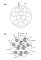
- FIG. 1 is an explanatory diagram of the optical cable 1.
- FIG. 2A is an explanatory diagram of the optical fiber unit 11.
- FIG. 2B is an explanatory diagram of another optical fiber unit 11.
- FIG. 3 is an explanatory diagram of the arrangement of the intervening member 17A of a certain optical fiber unit 11A.
- FIG. 4 is a table showing the evaluation results of the disassembly workability of the optical cable 1.
- FIG. 5 is an explanatory diagram of the manufacturing system 40 of the optical cable 1.
- 6A and 6B are explanatory views of the panel 44.
- 7A to 7C are explanatory views of a state when the eye plate 44 rotates.
- FIG. 8 is an explanatory diagram of the manufacturing system 40 of the modified example.
- FIG. 9A is an explanatory diagram of the state of measurement of the compression ratio R.
- FIG. 9B is an explanatory diagram of a change in the cross-sectional shape before and after applying the lateral pressure.
- FIG. 10 shows the measurement results of the compressibility of the intervening member, the bundle material, and the Kevlar.
- FIG. 11 is a graph showing the relationship between the applied load P and the compression ratio R.
- FIG. 12 is a cross-sectional explanatory view of the intervening member 17 in the optical cable 1.
- a plurality of optical fiber units having a fiber bundle composed of a plurality of optical fibers are provided, and the plurality of optical fiber units are twisted in an SZ shape, and an intervening member is wound around the outer periphery of at least one fiber bundle.
- An optical cable characterized by being present is revealed. According to such an optical cable, it is possible to suppress untwisting of the optical fiber unit while reducing the number of intervening members.
- the optical fiber unit includes a bundle material for bundling the plurality of optical fibers. As a result, the optical fibers can be bundled without being separated.
- the intervening member is wound around the outside of the bundle material. This makes it easier for the intervening member to come into contact with the surrounding optical fiber unit, so that it is possible to further suppress untwisting of the optical fiber unit while reducing the number of intervening members.
- optical fiber unit having the intervening member It is desirable to include the optical fiber unit having the intervening member and the optical fiber unit not having the intervening member. This makes it easier to reduce the number of intervening members.
- the optical fiber unit constitutes an inner layer unit, and the outer layer unit is configured by arranging a plurality of the optical fiber units in the circumferential direction outside the inner layer unit, and the optical fiber unit constituting the inner layer unit is , It is desirable to have the intervening member. Further, under such a situation, it is desirable that the outer layer unit includes the optical fiber unit having the intervening member and the optical fiber unit having no intervening member. As a result, it is possible to further suppress untwisting of the optical fiber unit while reducing the number of intervening members.
- the optical fiber unit having no intervening member is arranged between the two optical fiber units having the intervening member of the outer layer unit. As a result, it is possible to further suppress untwisting of the optical fiber unit while reducing the number of intervening members.
- the intervening member is wound around the outer periphery of the fiber bundle in an SZ shape without being joined to other members. Since the intervening member does not need the function of bundling a plurality of optical fibers, it can be wound around the outer periphery of the fiber bundle in an SZ shape without being joined to other members.
- the load applied to the winding member wound around the outer periphery of the intervening member is P (N), and the compression rate of the intervening member when the load P is applied to the winding member and a lateral pressure is applied to the intervening member.
- R it is desirable that the compression ratio R increases as the load P increases when the load P is 1N or more. This makes it possible to suppress untwisting of the optical fiber unit.
- the compression ratio R increases as the load P increases in the range of the load P of 1.5 to 2.0 N. This makes it possible to suppress untwisting of the optical fiber unit.
- ⁇ When the ratio of the increase in the compressibility R to the increase in the load P in the range of 1.5 to 2.0 N is ⁇ (N -1 ), ⁇ may be 0.17 or more. desirable. This makes it possible to suppress untwisting of the optical fiber unit.
- the load applied to the winding member wound around the outer periphery of the intervening member is P (N), and the compression rate of the intervening member when the load P is applied to the winding member and a lateral pressure is applied to the intervening member.
- R it is desirable that the inclusions can be deformed to have a compression ratio R of 0.57 or more. This makes it possible to suppress untwisting of the optical fiber unit.
- An optical cable manufacturing method for winding the intervening member around the outer periphery of the fiber bundle will be clarified. According to such an optical cable manufacturing method, it is possible to manufacture an optical cable in which untwisting of the optical fiber unit is suppressed while reducing the number of intervening members.
- optical fiber unit 11 having a distorted cross-sectional shape as shown in FIG. 1B may be shown as having a circular cross-section as shown in FIG. 1A.
- the intervening member 17 having a distorted cross-sectional shape may be shown as a circular shape, an elliptical shape, or the like having a well-defined cross-sectional shape.
- the optical cable 1 is a cable accommodating an optical fiber.
- the optical cable 1 of the present embodiment is an optical cable having no slot rod in which a slot (groove for accommodating an optical fiber) is formed, and is a so-called slotless type optical cable.
- the optical cable 1 may be a slot-type optical cable having a slot rod.
- the optical cable 1 has a core 10 and an outer cover 20.
- the core 10 is a member housed in the outer cover 20.
- the core 10 has a plurality of optical fiber units 11 (11A to 11J) and a presser foot winding tape 18. As shown in FIG. 1A (or FIG. 1B), the core 10 of the present embodiment has 10 optical fiber units 11, but the number of optical fiber units 11 is not limited to 10. Further, the core 10 of the present embodiment is configured by twisting a plurality of optical fiber units 11 in an SZ shape.
- the presser foot tape 18 is a member that wraps the plurality of optical fiber units 11.
- the inner layer unit 12 and the outer layer unit 13 are configured by a plurality of optical fiber units 11 constituting the core 10.
- the inner layer unit 12 is an optical fiber unit 11 arranged in the central portion of the core 10.
- the outer layer unit 13 is an optical fiber unit 11 arranged outside the inner layer unit 12.
- the inner layer unit 12 is composed of three optical fiber units 11, and the outer layer unit 13 is composed of seven optical fiber units 11.
- the number of optical fiber units 11 constituting the inner layer unit 12 and the outer layer unit 13 is not limited to this.
- a to C may be added to the code of the optical fiber unit 11 constituting the inner layer unit 12, and D to J may be added to the code of the optical fiber unit 11 constituting the outer layer unit 13.
- the reference numerals of the members corresponding to the optical fiber unit 11 may be subscripted in the same manner as the corresponding optical fiber unit 11.
- the outer cover 20 is a member that covers a plurality of optical fiber units 11 (and presser foot winding tape 18).
- the outer shape of the outer cover 20 is substantially circular in cross section, but the outer shape of the outer cover 20 is not limited to the circular shape.
- a tension member 21 is embedded in the outer cover 20. Further, not only the tension member 21 but also other members (for example, the ripcord 22) may be embedded in the outer cover 20.
- FIG. 2A is an explanatory diagram of the optical fiber unit 11.
- the optical fiber unit 11 is a structure in which a plurality of optical fibers 15 are bundled.
- the optical fiber unit 11 shown in FIG. 2A has a fiber bundle 14 and a bundle material 16.
- the fiber bundle 14 is a bundle of a plurality of optical fibers 15.
- the fiber bundle 14 is configured by bundling a plurality of intermittently connected optical fiber tapes.
- the fiber bundle 14 does not have to be composed of a plurality of intermittently connected optical fiber tapes, and may be composed of, for example, one intermittently connected optical fiber tape, or a plurality of single cores. It may be composed of an optical fiber.
- the bundle material 16 is a member for bundling a plurality of optical fibers 15 constituting the fiber bundle 14.
- the bundle material 16 is wound around the outer circumference of the fiber bundle 14.
- the plurality of optical fibers 15 constituting the fiber bundle 14 are bundled so as not to be separated.
- the optical fiber unit 11 has a pair of bundle materials 16, and each bundle material 16 is wound around the outer periphery of the fiber bundle 14 in an SZ shape so that the winding directions are opposite at the junction. Has been done.
- the bundle material 16 is not limited to the one wound in an SZ shape, and may be spirally wound around the outer periphery of the fiber bundle 14 in one direction.
- the number of bundle materials 16 is not limited to two.
- the optical fiber unit 11 is composed of one piece of intermittently connected optical fiber tape, the bundle of the optical fibers 15 does not fall apart, so that the optical fiber unit 11 does not include the bundle material 16. Is also good.
- FIG. 2B is an explanatory diagram of another optical fiber unit 11.
- Some optical fiber units 11 11A-11C, 11G, 11J; see FIG. 1A of this embodiment further include an intervening member 17.
- the intervening member 17 is a member that fills the gap in the internal space of the optical cable 1.
- the mounting density of the optical fiber 15 can be increased.
- the mounting density of the optical fiber 15 is the area obtained by subtracting the cross-sectional area of members other than the optical fiber 15 (presser winding tape 18, bundle material 16, intervening member 17, etc.) from the total cross-sectional area of the internal space of the optical cable 1.
- the total cross-sectional area of the internal space of the optical cable 1 is S0
- the total cross-sectional area of the members other than the optical fiber 15 (presser winding tape 18, bundle material 16, intervening member 17, etc.) inside the optical cable 1 is S1.
- the total cross-sectional area of the optical fiber 15 inside the optical cable 1 is Sf
- the mounting density of the optical fiber 15 is ⁇
- ⁇ Sf / (S0-S1).
- the voids in the internal space of the optical cable 1 increase, so that the plurality of optical fiber units 11 twisted in an SZ shape may move in a direction in which the twist is eliminated. .. That is, if the mounting density of the optical fiber 15 is low, "untwisting" of the optical fiber unit 11 may occur. On the other hand, if the number of intervening members 17 arranged inside the optical cable 1 is increased too much in order to suppress "untwisting", the lateral pressure applied to the optical fiber 15 increases, and the microbend loss of the optical fiber 15 increases.
- a low-loss optical fiber for example, an optical fiber having low-loss characteristics conforming to ITU-T G.654.E
- ITU-T G. 657 Since the microbend characteristics are inferior to those of an optical fiber conforming to A1, if many intervening members 17 are arranged inside the optical cable 1 using such an optical fiber, the microbend loss increases. It will be easier. Therefore, in the present embodiment, as described below, the number of intervening members 17 is reduced while suppressing the “untwisting” of the optical fiber unit 11.
- the intervening member 17 of the present embodiment is a long member, and is wound around the outer periphery of the fiber bundle 14 in a spiral or SZ shape along the longitudinal direction.
- the intervening member 17 of the present embodiment is a string-shaped member, but is not limited to the string-shaped member, and may be, for example, a tape-shaped member.
- the intervening member 17 of the present embodiment is made of a polypropylene string, but the material of the intervening member 17 is not limited to polypropylene, and other materials may be used.
- the intervening member 17 may be a member having water absorption such as a water absorption yarn. Since the intervening member 17 has water absorption, running water inside the optical cable 1 can be suppressed. In FIG.
- the intervening member 17 is spirally wound around the outer circumference of the fiber bundle 14 in one direction.
- the intervening member 17 may be wound in an SZ shape around the outer periphery of the fiber bundle 14 by reversing the winding direction in the middle.
- the intervening member 17 is a member having a cushioning property as compared with the bundle material 16. Therefore, the intervening member 17 is a member whose cross-sectional shape changes significantly when lateral pressure is applied (in contrast, the bundle material 16 is a member having a small amount of deformation whose cross-sectional shape hardly deforms even when lateral pressure is applied). .. Further, the intervening member 17 has a property that the cross-sectional shape is deformed even with a small lateral pressure and the cross-sectional shape is easily restored to the original shape when the lateral pressure is removed (high restoration rate).
- the intervening member 17 Since the intervening member 17 has such a cushioning property, even if the internal space of the optical cable 1 is deformed when the cable is curved, the intervening member 17 can continue to fill the internal gap of the optical cable 1 by following the deformation of the internal space. Therefore, it is possible to maintain the posture of the member (for example, the optical fiber unit 11) in the internal space of the optical cable 1, and it is possible to suppress the "untwisting" of the optical fiber unit 11.
- the optical fiber unit 11 (and the fiber bundle 14) is drawn extending linearly in the longitudinal direction, but in the present embodiment, a plurality of optical fiber units 11 are twisted inside the optical cable 1. Since they are combined, the longitudinal direction of the optical fiber unit 11 extends in an SZ shape along the longitudinal direction of the optical cable 1. That is, the optical fiber unit 11 (and the fiber bundle 14) is arranged in the longitudinal direction inside the optical cable 1 in an SZ shape, and the intervening member 17 of the present embodiment is in the longitudinal direction of such an SZ-shaped fiber bundle 14. The intervening member 17 is wound spirally or in an SZ shape along the above.
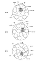
- FIG. 3 is an explanatory diagram of the arrangement of the intervening member 17A of a certain optical fiber unit 11A.
- FIG. 3 shows a cross section of the optical cable 1 at different locations in the longitudinal direction of the optical cable 1.
- the plurality of optical fiber units 11 in the optical cable 1 are drawn so as to be at the same position by changing the position in the circumferential direction of the cross section of the optical cable 1 (in the present embodiment, the optical cable 1 is drawn. Since a plurality of optical fiber units 11 are internally twisted in an SZ shape, the position of the optical fiber unit 11 in the cross section of the optical cable 1 differs depending on the position in the longitudinal direction of the optical cable 1).
- the intervening member 17 is spirally or SZ-shaped around the outer circumference of the fiber bundle 14 along the longitudinal direction (see FIG. 2B), as shown in FIG. 3, a certain optical fiber unit 11A
- the intervening member 17A can be adjacent not only to a specific optical fiber unit 11 but also to other surrounding optical fiber units 11.
- the intervening member 17A of a certain optical fiber unit 11A shown in FIG. 3 is adjacent to the optical fiber unit 11D of the outer layer unit 13 in a certain cross section, and is adjacent to the optical fiber unit 11B of the inner layer unit 12 in another cross section. do.
- the intervening member 17A of a certain optical fiber unit 11A shown in FIG. 3 is adjacent to a plurality of different optical fiber units 11.
- the intervening member 17 of the other optical fiber unit 11 is also wound around the outer periphery of the fiber bundle 14 in a spiral or SZ shape along the longitudinal direction so as to be adjacent to a plurality of different optical fiber units 11. ..
- the intervening member 17 of a certain optical fiber unit 11 is adjacent to a plurality of optical fiber units 11 having different surroundings, so that the intervening member 17 is adjacent to many optical fiber units 11. Since the optical fiber unit 11 adjacent to the intervening member 17 is likely to be held in a posture (a posture twisted in an SZ shape) by the intervening member 17, the intervening member 17 is in a state of being adjacent to many optical fiber units 11. Therefore, the "untwisting" of the optical fiber unit 11 can be suppressed.
- the intervening member 17 is wound around the outer periphery of the fiber bundle 14 in a spiral or SZ shape along the longitudinal direction, so that the intervening member 17 is reduced and the “untwisting” of the optical fiber unit 11 is performed. It can be suppressed.
- the intervening member 17 is wound around the outside of the bundle material 16.
- the intervening member 17 is more likely to come into contact with the surrounding optical fiber unit 11 as compared with the case where the intervening member 17 is arranged inside the bundle material 16, so that the optical fiber unit 11 is "twisted". "Return" can be further suppressed.
- all the optical fiber units 11 do not have the intervening member 17, and the optical fiber unit 11 (11A to 11C, 11G, 11J; see FIG. 2B) having the intervening member 17. ) And the optical fiber unit 11 (11D to 11F, 11H, 11I; see FIG. 2A) having no intervening member 17.
- the optical fiber unit 11 having no intervening member 17 is adjacent to the intervening member 17 of the adjacent optical fiber unit 11 to suppress "untwisting"
- the optical fiber unit 11 having no intervening member 17 can be used. Mixing is allowed. However, all the optical fiber units 11 may have an intervening member 17.
- each of the three optical fiber units 11 (11A to 11C) constituting the inner layer unit 12 has an intervening member 17. Since the optical fiber unit 11 constituting the inner layer unit 12 has a larger number of optical fiber units 11 adjacent to the periphery than the optical fiber units 11 (11D to 11J) constituting the outer layer unit 13, as in the present embodiment. Since the optical fiber unit 11 constituting the inner layer unit 12 has the intervening member 17, the intervening member 17 is in a state of being adjacent to many optical fiber units 11. As a result, the optical fiber unit 11 can easily maintain the twisted posture in an SZ shape, and thus it becomes easy to suppress the "untwisting" of the optical fiber unit 11. However, the optical fiber unit 11 constituting the inner layer unit 12 does not have to have the intervening member 17.
- the outer layer unit 13 includes an optical fiber unit 11 having an intervening member 17 and an optical fiber unit 11 having no intervening member 17. This makes it possible to reduce the number of intervening members 17 inside the optical cable 1.
- the optical fiber unit 11 of the inner layer unit 12 since the optical fiber unit 11 of the inner layer unit 12 has an intervening member 17, even if the outer layer unit 13 has an optical fiber unit 11 having no intervening member 17, the outer layer unit thereof is present. Since the optical fiber unit 11 of 13 is adjacent to at least the intervening member 17 of the optical fiber unit 11 of the inner layer unit 12, it is possible to suppress "untwisting" of the optical fiber unit 11 of the outer layer unit 13.
- the two optical fiber units 11 having the intervening member 17 and the optical fiber unit 11 having no intervening member 17 are mixed in the outer layer unit 13, the two optical fiber units 11 having the intervening member 17 are in the circumferential direction. It is desirable that the optical fiber unit 11 having no intervening member 17 is arranged between them. As a result, even if the number of intervening members 17 inside the optical cable 1 is reduced as compared with the case where the two optical fiber units 11 having the intervening members 17 in the outer layer unit 13 are adjacent to each other in the circumferential direction, the optical fiber unit 11 is "twisted back". It becomes easy to suppress.
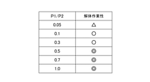
- the winding pitch of the intervening member 17 is set to P1
- the twist pitch of the plurality of optical fiber units 11 is set to P2
- a plurality of types of optical cables 1 with modified P1 / P2 are created, and the disassembly workability of each optical cable 1 is improved. evaluated.
- the winding pitch of the intervening member 17 is defined as the length of the fiber bundle 14 until the intervening member 17 spirally wound around the outer circumference of the fiber bundle 14 makes one round in the circumferential direction. The length of the direction.
- the twist pitch P2 is the length in the longitudinal direction of the optical cable 1 from the time when the twist direction of the optical fiber unit 11 twisted in the SZ shape is reversed until the next time the twist direction is reversed in the same direction. ..
- the created optical cable 1 has the structure shown in FIG. 1A (or FIG. 1B), and the optical fiber unit 11 is composed of five 4-core intermittently connected optical fiber tapes, and the ten optical fiber units 11 are formed in an SZ shape. It was constructed by twisting it together. Further, the intervening member 17 was spirally wound around five of the ten optical fiber units 11.
- the dismantling workability of the optical cable 1 when the intervening member 17 is vertically attached without being wound around the fiber bundle 14 (when P1 is infinite) is used as a reference, and the case where the dismantling workability is almost unchanged is regarded as excellent ( ⁇ ).
- the dismantling workability of each optical cable 1 was evaluated by considering the case where there is no problem in dismantling workability as good ( ⁇ ) and the case where dismantling is possible but it takes time ( ⁇ ).
- FIG. 4 is a table showing the evaluation results of the disassembly workability of the optical cable 1.
- P1 / P2 is preferably 0.1 or more (P1 / P2 ⁇ 0.1). Further, it is more desirable that P1 / P2 is 0.5 or more (P1 / P2 ⁇ 0.5).
- the intervening member 17 may be wound around the outer circumference of the fiber bundle 14 in an SZ shape.
- the intervening member 17 is wound around the outer periphery of the fiber bundle 14 in an SZ shape, the work of removing the intervening member 17 becomes easier as compared with the case where the intervening member 17 is wound in a spiral shape.
- the intervening member 17 is wound around the outer periphery of the fiber bundle 14 in an SZ shape without being joined to another member (for example, another intervening member 17 when the optical fiber unit 11 has two or more intervening members 17). It is desirable that it is. This facilitates the work of removing the intervening member 17.
- the intervening member 17 does not need a function of bundling a plurality of optical fibers 15, so that the intervening member 17 is wound around the outer periphery of the fiber bundle 14 in an SZ shape without being joined to other members to form an optical fiber unit. 11 can be configured. Further, unlike the bundle material 16, the intervening member 17 does not need a function of bundling a plurality of optical fibers 15, so that the number of intervening members 17 wound around the outer periphery of the fiber bundle 14 of the optical fiber unit 11 is one. , The one fiber bundle 14 may be wound around the outer periphery of the fiber bundle 14 in an SZ shape.
- the bundle material 16 bundles a plurality of optical fibers 15 when wound in an SZ shape, it is joined to another bundle material 16 to be paired, whereas the intervening member 17 is wound in an SZ shape even when it is wound in an SZ shape. Since the number of intervening members can be reduced to one, it becomes easy to suppress the number of intervening members 17 included in the optical cable 1.
- the optical cable 1 of the present embodiment includes a plurality of optical fiber units 11 having a fiber bundle 14 composed of a plurality of optical fibers 15, and the plurality of optical fiber units 11 are twisted in an SZ shape.
- the intervening member 17 is wound around the outer periphery of at least one fiber bundle 14. According to the optical cable 1 having such a configuration, as shown in FIG. 3, the intervening member 17 can be adjacent to a plurality of optical fiber units 11 having different surroundings. As a result, the optical fiber unit 11 adjacent to the intervening member 17 can easily maintain the posture twisted in an SZ shape by the intervening member 17. As a result, it is possible to suppress "untwisting" of the optical fiber unit 11 while reducing the number of intervening members 17.
- the five optical fiber units 11 each include an intervening member 17, but at least one of the plurality of optical fiber units 11 includes the intervening member 17. If the intervening member 17 is wound around the outer periphery of the fiber bundle 14, it is possible to suppress the "untwisting" of the optical fiber unit 11 while reducing the intervening member 17.
- FIG. 5 is an explanatory diagram of the manufacturing system 40 of the optical cable 1.
- the manufacturing system 40 includes a fiber supply unit 41, a bundle device 42, an intervening supply unit 43, a perforated plate 44, an extrusion molding unit 45, and a winding unit 47.
- the fiber supply unit 41 is a device (supply source) for supplying the optical fiber 15.
- the fiber supply unit 41 is a device (supply source) for supplying an intermittently connected optical fiber tape, and can supply a plurality of optical fibers 15.
- the fiber supply unit 41 is composed of a drum (or bobbin) on which an intermittently connected optical fiber tape is wound in advance.
- the fiber supply unit 41 may be composed of an intermittently connected optical fiber tape manufacturing apparatus.
- the optical fiber tape supplied from the fiber supply unit 41 is supplied to the bundle device 42 as a fiber bundle 14.
- the bundle device 42 is a device for winding the bundle material 16 around the outer circumference of the fiber bundle 14.
- the bundle device 42 winds the two bundle materials 16 in an SZ shape in opposite directions to each other, and joins the two bundle materials 16 at the inverted portion in the winding direction.
- the bundle device 42 may spirally wind the bundle material 16 around the outer circumference of the fiber bundle 14 in one direction.
- the optical fiber unit 11 shown in FIG. 2A is formed.
- the bundle device 42 may not be provided.
- the intervening supply unit 43 is a device (supply source) for supplying the intervening member 17.
- the intervening supply unit 43 is composed of a drum (or bobbin) around which the intervening member 17 is wound in advance.
- FIG. 6A and 6B are explanatory views of the panel 44.
- FIG. 6A is an explanatory view of the eye plate 44.
- FIG. 6B is an explanatory diagram of a state in which the optical fiber unit 11 (fiber bundle 14 and the bundle material 16) and the intervening member 17 are inserted into the insertion hole 441 of the panel 44.
- the panel 44 is a plate-shaped member having a plurality of insertion holes 441.
- the insertion hole 441 is a through hole that penetrates the eye plate 44, and is a hole for inserting the fiber bundle 14 and the intervening member 17.
- the insertion hole 441 is configured in a circular shape.
- the optical fiber unit 11 (fiber bundle 14) is supplied from the bundle device 42, and the intervening member 17 is supplied from the intervening supply unit 43 toward each insertion hole 441 of the panel 44. As shown in FIG. 5, the supply direction of the optical fiber unit 11 to the panel 44 and the supply direction of the intervening member 17 are different.
- the supply direction of the optical fiber unit 11 to the eye plate 44 is substantially perpendicular to the eye plate 44, whereas the supply direction of the intervening member 17 to the eye plate 44 is the eye plate. It is tilted with respect to the vertical direction of 44.
- the panel 44 swings around the central rotation axis with the fiber bundle 14 and the intervening member 17 inserted through the insertion hole 441. By swinging the panel 44, the plurality of optical fiber units 11 are twisted in an SZ shape. Further, the eye plate 44 of the present embodiment also has a function of arranging the intervening member 17 on the outer periphery of the fiber bundle 14 in an SZ shape by swinging.
- 7A to 7C are explanatory views of the state when the eye plate 44 rotates.
- a state in which the fiber bundle 14 and the intervening member 17A are inserted through only one insertion hole 441A is shown.
- the position of the fiber bundle 14 in the circumferential direction changes due to the swing of the panel 44.
- the fiber bundle 14 (optical fiber unit 11A) is arranged in an SZ shape along the longitudinal direction inside the optical cable 1.
- the supply direction of the intervening member 17 to the panel 44 is inclined with respect to the vertical direction of the panel 44.
- the intervening member 17 tends to be unevenly arranged on the side of the intervening supply portion 43 inside the insertion hole 441.
- the intervening supply portion 43 (see FIG. 5) of the intervening member 17 shown in FIGS. 7A to 7C is arranged on the upper side in the drawing with respect to the insertion hole 441 of the panel 44, and as a result, FIGS. 7A to 7C.
- the intervening member 17A shown in the above is likely to be unevenly arranged on the upper side (upper edge) of the insertion hole 441 inside the insertion hole 441A.
- the intervening member 17 swings in a state where the intervening member 17 is unevenly arranged in a specific direction inside the insertion hole 441, whereby the intervening member 17 is placed on the outer periphery of the fiber bundle 14 in the longitudinal direction. It can be wound in an SZ shape along the line.
- the insertion hole 441 is configured in a circular shape.
- the fiber bundle 14 and the intervening member 17 and the peripheral edge of the insertion hole 441 are in the circumferential direction (direction along the peripheral edge of the insertion hole 441). It becomes easy to slip, and it becomes easy to displace the intervening member 17 in a specific direction (here, the upper side) inside the insertion hole 441.
- the shape of the insertion hole 441 does not have to be circular and may be another shape as long as the intervening member 17 can be arranged unevenly in a specific direction inside the insertion hole 441.
- the intervening member 17 is adjacent to the specific optical fiber unit 11 by swinging the eye plate 44 in a state where the intervening member 17 is unevenly arranged in a specific direction inside the insertion hole 441. Not only does it allow it to be adjacent to other surrounding fiber optic units 11.
- the intervening member 17A shown in FIG. 7A is adjacent to the optical fiber unit 11D (not shown in FIG. 7B; see FIG. 3) inserted into the insertion hole 441D in the state shown in FIG. 7B, and in the state shown in FIG. 7C.
- Adjacent to the optical fiber unit 11B (not shown in FIG. 7C; see FIG. 3) inserted through the insertion hole 441B.
- the intervening member 17 inserted into the other insertion hole 441 also has a plurality of different optical fiber units 11 due to the swing of the panel 44 in a state of being biased in a specific direction inside the insertion hole 441. Can be adjacent to.
- the plurality of optical fiber units 11 that have passed through the panel 44 are supplied to the extrusion molding unit 45 in a state of being twisted in an SZ shape.
- the plurality of optical fiber units 11 are supplied to the extrusion molding unit 45.
- other members such as the presser foot tape 18, the tension member 21, and the ripcord 22 are supplied to the extrusion molding unit 45.
- the extrusion molding unit 45 is a device for forming the outer cover 20.
- the presser foot tape 18 is wound around a plurality of optical fiber units 11 and the resin to be the outer cover 20 is extruded, whereby the optical cable of the present embodiment shown in FIG. 1A (or FIG. 1B) is extruded. 1 will be manufactured.
- the optical cable 1 manufactured by the extrusion molding unit 45 is cooled by the cooling device 46 and then wound up by the winding unit 47 (for example, a drum).
- the fiber bundle 14 is inserted into each of the plurality of insertion holes 441 of the panel 44, and the intervening member 17 is inserted in at least one insertion hole 441 of the panel 44. Insertion and winding of the intervening member 17 around the outer periphery of at least one fiber bundle 14 by swinging the eye plate 44 are performed. According to such a manufacturing method, it is possible to manufacture the optical cable 1 in which the "untwisting" of the optical fiber unit 11 is suppressed while reducing the number of intervening members 17.
- FIG. 8 is an explanatory diagram of the manufacturing system 40 of the modified example.
- the manufacturing system 40 of the modified example includes a fiber supply unit 41, a bundle device 42, an intervening winding unit 43', a panel 44, an extrusion molding unit 45, and a winding unit 47.
- the modified manufacturing system 40 has an intervening winding unit 43'instead of the above-mentioned intervening supply unit 43 (see FIG. 5).
- the intervening winding portion 43' is a device for winding the intervening member 17 around the outer periphery of the fiber bundle 14.
- the intervening winding portion 43' is a device that spirally winds the intervening member 17 around the outer periphery of the fiber bundle 14.
- the intervening member 17 may be wound around the outer periphery of the fiber bundle 14 in an SZ shape.
- the panel 44 swings around the central rotation axis with the fiber bundle 14 and the intervening member 17 inserted through the insertion hole 441.
- the plurality of optical fiber units 11 are twisted in an SZ shape.
- a plurality of optical fiber units 11 are twisted in an SZ shape in a state where the intervening member 17 is spirally or SZ-shaped around the outer circumference of the fiber bundle 14. Therefore, in the modified example, the winding pitch P1 of the intervening member 17 and the twist pitch P2 of the plurality of optical fiber units 11 can be easily set separately.
- the intervening member 17 is a member whose cross-sectional shape changes significantly when lateral pressure is applied.
- the compression ratio is an example of an index showing a change in the cross-sectional shape when a lateral pressure is applied.
- the length of the outer circumference of the member before applying the lateral pressure is L1 (mm)
- the length of the outer circumference of the member when the lateral pressure is applied is L2 (mm).
- the compression ratio R of the member is as follows.
- FIG. 9A is an explanatory diagram of the state of measurement of the compression ratio R.
- FIG. 9B is an explanatory diagram of a change in the cross-sectional shape before and after applying the lateral pressure.
- one end of the member to be measured 19 (for example, the intervening member 17) is fixed, and a weight is attached to the other end to apply tension to the member 19 to be measured.
- a weight of 200 g is applied (a tension of about 2 N is applied) so that the same tension as that of the intervening member 17 in the optical cable 1 is applied.
- FIG. 9B On the left side of FIG. 9B, the state before applying the load to the winding member 53 is shown. On the right side of FIG. 9B, a state in which a load is applied to the winding member 53 is shown.
- a string-shaped winding member 53 is wound around the outer periphery of the member to be measured 19 (for example, the intervening member 17). Further, as shown in FIGS. 9A and 9B, one end of the member to be measured 19 is fixed, and the measuring device 52 is attached to the other end.
- the measuring device 52 measures the load P (N) applied to the winding member 53 and the displacement X (mm) of the end portion of the winding member 53 with respect to the reference position X0.
- the initial circumference length of the member 19 to be measured is L1 and the diameter is D1.
- a load P tensile load
- lateral pressure is evenly applied to the outer circumference of the member to be measured 19, and the cross-sectional shape of the member 19 to be measured is deformed by compression.
- the circumference of the member 19 to be measured becomes L2, and the diameter becomes D2 (the density of the member 19 to be measured becomes high).
- the end portion of the winding member 53 is displaced.
- the circumference length L2 (or diameter D2) of the member 19 to be measured can be measured, whereby the compression ratio can be measured.
- R can be calculated.
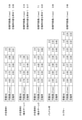
- FIG. 10 shows the measurement results of the compressibility of the intervening member, the bundle material, and the Kevlar.
- three types of intervening members (intervening members 1 to 3), a bundle material, and a Kevlar were measured as the members to be measured.
- an optical cable configured by winding a bundle material or a kebler to be measured around the outer periphery of an optical fiber unit a plurality of twisted optical fiber units are untwisted, whereas an intervening member to be measured (intervening member 1) is used.
- an intervening member to be measured is used in the optical cable configured by winding 3 around the outer periphery of the optical fiber unit, untwisting of the optical fiber unit was suppressed.
- the intervening members 2 and 3 are intervening members having water absorption, and specifically, they are water absorbing yarns. Further, here, the applied load P is different in the range of 0.0 to 2.5 N, and as shown in FIG. 9B, the circumference length L2 when the load P is applied to the winding member 53 is measured, and the initial circle is measured. The compression ratio R was measured based on the circumference L1 and the circumference L2.
- FIG. 11 is a graph showing the relationship between the applied load P and the compression ratio R.
- the horizontal axis of the graph shows the tensile load P (N) applied to the winding member 53 of FIGS. 9A and 9B.
- the vertical axis of the graph shows the compressibility R of the member 19 to be measured.
- the compression ratio R increased as the applied load P increased in the range where the applied load P was 1.0 N or more. That is, while the bundle material and Kevlar are members whose cross-sectional shape is unlikely to change when lateral pressure is applied, the intervening member has a larger cross-sectional shape when lateral pressure is applied than the bundle material and Kevlar. It has been shown to be a changing member.
- the gap inside the optical cable 1 can be continuously filled, whereby the posture of the member (for example, the optical fiber unit 11) in the internal space of the optical cable 1 can be continuously filled. It is possible to hold. Therefore, as shown in FIG. 11, it is desirable that the compressibility R of the intervening member increases as the applied load P increases. In particular, it is desirable that the compressibility R of the intervening member increases as the applied load P increases when the applied load P is 1.0 N or more. It is considered that increasing the compressibility R as the applied load P increases in the range where the applied load P exceeds 1.0 N is also effective in suppressing the microbend loss of the optical fiber.
- the compressibility R did not change in the range of the applied load P of 1.5 to 2.0 N. This means that when the applied load P reaches 1.5 to 2.0 N, the cross-sectional shape of the bundle material and Kevlar does not change even if the lateral pressure changes, and the applied load P is 1. It means that the cross-sectional shape of the bundle material and Kevlar does not change when it exceeds 5N.
- the compression ratio R increases as the applied load P increases in the range of the applied load P of 1.5 to 2.0 N.
- the intervening members can change the cross-sectional shape even if the applied load P exceeds 1.5 N, unlike the bundle material and the Kevlar.
- the intervening members (intervening members 1 to 3) are compared with the bundle material and the Kevlar, a large difference appears in the change in the compression ratio R in the range of the applied load P of 1.5 to 2.0 N.
- the untwisting of the optical fiber unit was suppressed in the optical cable configured by winding the intervening members (intervening members 1 to 3) around the outer periphery of the optical fiber unit due to the difference in the change in the compression ratio R. Therefore, it is desirable that the inclusions have a property that the compressibility R increases as the applied load P increases, at least in the range of the applied load P of 1.5 to 2.0 N.
- the rate of change ⁇ of the compressibility in the range of the applied load P in the range of 1.5 to 2.0 N (the ratio of the amount of increase in the compressibility R to the amount of increase in the applied load P) is shown.
- a member having a large value of the rate of change ⁇ of the compression rate has a characteristic that the compression rate R tends to increase as the applied load P increases.
- the rate of change ⁇ of the compressibility of each member shown in FIG. 10 corresponds to the slope of the graph in the range where the applied load P in FIG. 11 is in the range of 1.5 to 2.0 N, and the applied load P in FIG. 11 is 1.5 to 2. It corresponds to the slope of the line connecting the two measurement results in the range of 2.0N.
- the rate of change ⁇ in the compressibility of the intervening member is 0.17 to 0.26 (unit: N -1 ) (in contrast, the rate of change in the compressibility of the bundle material or Kevlar is almost zero).
- the intervening member 17 wound around the outer periphery of the fiber bundle 14 described above has a rate of change ⁇ of the compression rate in the range of the applied load P of 1.5 to 2.0 N (compression rate R with respect to the increase amount of the applied load P). It is desirable that the member has a rate of increase) of 0.17 or more.
- the maximum value of the compressibility R of the bundle material was 0.40, and the maximum value of the compression rate R of the Kevlar was 0.33.
- the maximum values of the compression ratio R were 0.91, 0.57, and 0.66, respectively, and the compression ratio R was larger than that of the bundle material and Kevlar.
- the compression ratio R hardly changes when the applied load P is 1.0 N or more, whereas in the case of the intervening members (intervening members 1 to 3), the applied load P is 1.0 N. This is because the compression ratio R also changes in the above, so that the cross-sectional shape changes significantly.
- the bundle material and Kevlar are members whose cross-sectional shape is less likely to change when lateral pressure is applied
- the intervening member is a member when lateral pressure is applied as compared with the bundle material and Kevlar. It is shown that the member has a large change in cross-sectional shape.
- the gap inside the optical cable 1 can be continuously filled, whereby the member in the internal space of the optical cable 1 (for example, an optical fiber unit) can be continuously filled. It is possible to maintain the posture of 11). Therefore, it is desirable that the intervening member can be deformed to have a compression ratio R of 0.57 or more.
- the cross-sectional shape of the intervening members changes significantly, and the cross-sectional shape of the intervening members (intervening members 1 to 3) changes significantly before the measurement. It was confirmed that it almost returned to the cross-sectional shape.
- the intervening member 17 wound around the outer periphery of the fiber bundle 14 has a property (high restoration rate) that the cross-sectional shape easily returns to the original shape when the lateral pressure is removed.
- FIG. 12 is a cross-sectional explanatory view of the intervening member 17 in the optical cable 1.
- FIG. 12 is an enlarged explanatory view of the periphery of a certain intervening member 17 of the optical cable 1 shown in FIG. 1B.
- the cross section of the intervening member 17 in the figure is hatched according to the density.
- the high-density portion of the intervening member 17 is heavily hatched, and the low-density portion is lightly hatched.
- the density of the intervening member 17 is relatively low (light hatching) in the portion filling the relatively wide gap inside the optical cable 1, and the density of the intervening member 17 is compared in the portion filling the relatively narrow gap inside the optical cable 1. Higher target (dark hatching). Therefore, it is considered that the region with high density receives a large lateral pressure from the surroundings as compared with the region with low density, and as a result, the region is significantly compressed and deformed. As described above, it is desirable that regions having different densities exist in a certain cross section of the intervening member 17.
- the density of the intervening member 17 is non-uniform in a certain cross section of the intervening member 17.
- the intervening member 17 is deformable so that there are regions having different densities in a certain cross section (it is desirable that the intervening member 17 is deformable so as to have different densities depending on the regions).
Landscapes
- Physics & Mathematics (AREA)
- General Physics & Mathematics (AREA)
- Optics & Photonics (AREA)
- Engineering & Computer Science (AREA)
- Manufacturing & Machinery (AREA)
- Optical Fibers, Optical Fiber Cores, And Optical Fiber Bundles (AREA)
- Light Guides In General And Applications Therefor (AREA)
- Insulated Conductors (AREA)
Priority Applications (7)
| Application Number | Priority Date | Filing Date | Title |
|---|---|---|---|
| JP2022546249A JP7457821B2 (ja) | 2020-09-02 | 2021-08-23 | 光ケーブル及び光ケーブル製造方法 |
| CA3187777A CA3187777A1 (en) | 2020-09-02 | 2021-08-23 | Optical cable and optical cable manufacturing method |
| CN202180056433.7A CN116075760A (zh) | 2020-09-02 | 2021-08-23 | 光缆以及光缆制造方法 |
| EP21864174.4A EP4209812A4 (en) | 2020-09-02 | 2021-08-23 | Optical cable and optical cable manufacturing method |
| AU2021336246A AU2021336246B2 (en) | 2020-09-02 | 2021-08-23 | Optical cable and optical cable manufacturing method |
| TW110132301A TWI799973B (zh) | 2020-09-02 | 2021-08-31 | 光纜及光纜製造方法 |
| US18/155,309 US11921341B2 (en) | 2020-09-02 | 2023-01-17 | Optical cable and optical cable manufacturing method |
Applications Claiming Priority (2)
| Application Number | Priority Date | Filing Date | Title |
|---|---|---|---|
| JP2020147296 | 2020-09-02 | ||
| JP2020-147296 | 2020-09-02 |
Related Child Applications (1)
| Application Number | Title | Priority Date | Filing Date |
|---|---|---|---|
| US18/155,309 Continuation US11921341B2 (en) | 2020-09-02 | 2023-01-17 | Optical cable and optical cable manufacturing method |
Publications (1)
| Publication Number | Publication Date |
|---|---|
| WO2022050116A1 true WO2022050116A1 (ja) | 2022-03-10 |
Family
ID=80490915
Family Applications (1)
| Application Number | Title | Priority Date | Filing Date |
|---|---|---|---|
| PCT/JP2021/030854 Ceased WO2022050116A1 (ja) | 2020-09-02 | 2021-08-23 | 光ケーブル及び光ケーブル製造方法 |
Country Status (8)
| Country | Link |
|---|---|
| US (1) | US11921341B2 (https=) |
| EP (1) | EP4209812A4 (https=) |
| JP (1) | JP7457821B2 (https=) |
| CN (1) | CN116075760A (https=) |
| AU (1) | AU2021336246B2 (https=) |
| CA (1) | CA3187777A1 (https=) |
| TW (1) | TWI799973B (https=) |
| WO (1) | WO2022050116A1 (https=) |
Families Citing this family (1)
| Publication number | Priority date | Publication date | Assignee | Title |
|---|---|---|---|---|
| US20240176089A1 (en) * | 2021-12-20 | 2024-05-30 | Sumitomo Electric Industries, Ltd. | Optical fiber cable |
Citations (5)
| Publication number | Priority date | Publication date | Assignee | Title |
|---|---|---|---|---|
| JP2014077869A (ja) * | 2012-10-10 | 2014-05-01 | Fujikura Ltd | 光ファイバケーブル |
| US20150370026A1 (en) * | 2014-06-23 | 2015-12-24 | Corning Optical Communications LLC | Optical fiber cable |
| JP2019056837A (ja) * | 2017-09-21 | 2019-04-11 | 住友電気工業株式会社 | 光ファイバケーブル |
| JP2019128363A (ja) * | 2018-01-19 | 2019-08-01 | 株式会社フジクラ | 光ファイバユニットの製造方法、光ファイバユニットの製造装置及び光ファイバユニット |
| JP2020076915A (ja) | 2018-11-09 | 2020-05-21 | 株式会社フジクラ | 光ファイバケーブル |
Family Cites Families (15)
| Publication number | Priority date | Publication date | Assignee | Title |
|---|---|---|---|---|
| GB8413205D0 (en) * | 1984-05-23 | 1984-06-27 | Telephone Cables Ltd | Optical fibre cables |
| GB8417869D0 (en) * | 1984-07-13 | 1984-08-15 | Telephone Cables Ltd | Optical fibre cables |
| FR2732120B1 (fr) * | 1995-03-24 | 1997-04-30 | Alcatel Cable | Cable a fibres optiques |
| US7277615B2 (en) * | 2002-12-19 | 2007-10-02 | Corning Cable Systems, Llc. | Fiber optic cable having a dry insert and methods of making the same |
| US8970845B1 (en) * | 2012-05-31 | 2015-03-03 | The United States Of America As Represented By The Administrator Of The National Aeronautics And Space Administration | In-situ three-dimensional shape rendering from strain values obtained through optical fiber sensors |
| JP6150422B2 (ja) | 2013-01-21 | 2017-06-21 | 株式会社フジクラ | 光ファイバケーブル |
| JP5956961B2 (ja) * | 2013-08-02 | 2016-07-27 | 株式会社フジクラ | 光ファイバケーブル |
| BR212016015377U2 (pt) * | 2013-12-30 | 2016-09-27 | Corning Optical Comm Llc | sistema de filme ligante |
| JP2017009924A (ja) | 2015-06-25 | 2017-01-12 | 古河電気工業株式会社 | 光ファイバユニット、光ファイバケーブル、および光ファイバユニットの製造方法 |
| JP6618744B2 (ja) * | 2015-09-18 | 2019-12-11 | 株式会社フジクラ | 光ファイバケーブル、光ファイバケーブルの製造方法および製造装置 |
| EP3988981B1 (en) | 2017-06-02 | 2023-09-13 | Fujikura Ltd. | Optical fiber cable |
| EP4279966A3 (en) * | 2017-08-08 | 2024-03-06 | Corning Research & Development Corporation | Rollable optical fiber ribbon with low attenuation, large mode field diameter optical fiber and cable |
| JP7068131B2 (ja) | 2018-10-15 | 2022-05-16 | 株式会社フジクラ | 光ファイバケーブル |
| CN116299923A (zh) | 2018-09-11 | 2023-06-23 | 株式会社藤仓 | 光纤电缆 |
| JP7068114B2 (ja) | 2018-09-11 | 2022-05-16 | 株式会社フジクラ | 光ファイバケーブル |
-
2021
- 2021-08-23 CN CN202180056433.7A patent/CN116075760A/zh active Pending
- 2021-08-23 AU AU2021336246A patent/AU2021336246B2/en active Active
- 2021-08-23 JP JP2022546249A patent/JP7457821B2/ja active Active
- 2021-08-23 CA CA3187777A patent/CA3187777A1/en active Pending
- 2021-08-23 WO PCT/JP2021/030854 patent/WO2022050116A1/ja not_active Ceased
- 2021-08-23 EP EP21864174.4A patent/EP4209812A4/en active Pending
- 2021-08-31 TW TW110132301A patent/TWI799973B/zh active
-
2023
- 2023-01-17 US US18/155,309 patent/US11921341B2/en active Active
Patent Citations (5)
| Publication number | Priority date | Publication date | Assignee | Title |
|---|---|---|---|---|
| JP2014077869A (ja) * | 2012-10-10 | 2014-05-01 | Fujikura Ltd | 光ファイバケーブル |
| US20150370026A1 (en) * | 2014-06-23 | 2015-12-24 | Corning Optical Communications LLC | Optical fiber cable |
| JP2019056837A (ja) * | 2017-09-21 | 2019-04-11 | 住友電気工業株式会社 | 光ファイバケーブル |
| JP2019128363A (ja) * | 2018-01-19 | 2019-08-01 | 株式会社フジクラ | 光ファイバユニットの製造方法、光ファイバユニットの製造装置及び光ファイバユニット |
| JP2020076915A (ja) | 2018-11-09 | 2020-05-21 | 株式会社フジクラ | 光ファイバケーブル |
Also Published As
| Publication number | Publication date |
|---|---|
| EP4209812A4 (en) | 2024-12-18 |
| TWI799973B (zh) | 2023-04-21 |
| EP4209812A1 (en) | 2023-07-12 |
| AU2021336246A1 (en) | 2023-03-16 |
| US20230152548A1 (en) | 2023-05-18 |
| CA3187777A1 (en) | 2022-03-10 |
| AU2021336246B2 (en) | 2024-03-28 |
| US11921341B2 (en) | 2024-03-05 |
| CN116075760A (zh) | 2023-05-05 |
| JP7457821B2 (ja) | 2024-03-28 |
| JPWO2022050116A1 (https=) | 2022-03-10 |
| TW202223461A (zh) | 2022-06-16 |
Similar Documents
| Publication | Publication Date | Title |
|---|---|---|
| JP7333438B2 (ja) | 光ファイバケーブル | |
| CN110268297B (zh) | 光纤缆线 | |
| CA3061885C (en) | Optical fiber cable and method of manufacturing optical fiber cable | |
| US11181706B2 (en) | Optical fiber cable | |
| JP7800448B2 (ja) | 光ファイバケーブル及びコネクタ付きケーブル | |
| KR20150010788A (ko) | 폴리에틸렌 바인더를 가진 광섬유 케이블 | |
| CN100458485C (zh) | 光纤组件、电缆及其制造方法 | |
| JP2006514324A (ja) | 直線集合構造のルースチューブ型光ケーブル | |
| US7421169B2 (en) | Optical fiber cable | |
| JPH10319284A (ja) | スペーサ型光ファイバケーブル | |
| JP7457821B2 (ja) | 光ケーブル及び光ケーブル製造方法 | |
| US4696541A (en) | Optical cable having a plurality of basic elements arranged in a common sheath | |
| CN211014752U (zh) | 一种微束管式柔性螺纹铠装光缆 | |
| US12585074B2 (en) | Optical cable | |
| US12105336B2 (en) | Optical cable | |
| TWI888328B (zh) | 光纜 | |
| JP7636555B2 (ja) | 光ケーブル及び光ケーブルの製造方法 | |
| US12204156B2 (en) | Optical cable | |
| KR20220028815A (ko) | 광케이블 | |
| WO2023127421A1 (ja) | 光ファイバ集合体、光ファイバケーブル、および光ファイバ集合体の製造方法 | |
| JP2005010651A (ja) | 光ファイバケーブル | |
| TW202605424A (zh) | 光纜及光纜之製造方法 | |
| JP2022101280A (ja) | 光ファイバケーブル | |
| CA3061669A1 (en) | Methods for forming fiber optic cables and fiber optic cables having helical buffer tubes |
Legal Events
| Date | Code | Title | Description |
|---|---|---|---|
| 121 | Ep: the epo has been informed by wipo that ep was designated in this application |
Ref document number: 21864174 Country of ref document: EP Kind code of ref document: A1 |
|
| ENP | Entry into the national phase |
Ref document number: 2022546249 Country of ref document: JP Kind code of ref document: A |
|
| WWE | Wipo information: entry into national phase |
Ref document number: 202317005853 Country of ref document: IN |
|
| ENP | Entry into the national phase |
Ref document number: 3187777 Country of ref document: CA |
|
| ENP | Entry into the national phase |
Ref document number: 2021336246 Country of ref document: AU Date of ref document: 20210823 Kind code of ref document: A |
|
| NENP | Non-entry into the national phase |
Ref country code: DE |
|
| ENP | Entry into the national phase |
Ref document number: 2021864174 Country of ref document: EP Effective date: 20230403 |