WO2022049764A1 - 飛行体 - Google Patents
飛行体 Download PDFInfo
- Publication number
- WO2022049764A1 WO2022049764A1 PCT/JP2020/033761 JP2020033761W WO2022049764A1 WO 2022049764 A1 WO2022049764 A1 WO 2022049764A1 JP 2020033761 W JP2020033761 W JP 2020033761W WO 2022049764 A1 WO2022049764 A1 WO 2022049764A1
- Authority
- WO
- WIPO (PCT)
- Prior art keywords
- main wing
- landing
- flying object
- angle
- wing
- Prior art date
- Legal status (The legal status is an assumption and is not a legal conclusion. Google has not performed a legal analysis and makes no representation as to the accuracy of the status listed.)
- Ceased
Links
Images









Classifications
-
- B—PERFORMING OPERATIONS; TRANSPORTING
- B64—AIRCRAFT; AVIATION; COSMONAUTICS
- B64U—UNMANNED AERIAL VEHICLES [UAV]; EQUIPMENT THEREFOR
- B64U10/00—Type of UAV
- B64U10/25—Fixed-wing aircraft
-
- B—PERFORMING OPERATIONS; TRANSPORTING
- B64—AIRCRAFT; AVIATION; COSMONAUTICS
- B64U—UNMANNED AERIAL VEHICLES [UAV]; EQUIPMENT THEREFOR
- B64U10/00—Type of UAV
- B64U10/20—Vertical take-off and landing [VTOL] aircraft
-
- B—PERFORMING OPERATIONS; TRANSPORTING
- B64—AIRCRAFT; AVIATION; COSMONAUTICS
- B64C—AEROPLANES; HELICOPTERS
- B64C27/00—Rotorcraft; Rotors peculiar thereto
- B64C27/22—Compound rotorcraft, i.e. aircraft using in flight the features of both aeroplane and rotorcraft
- B64C27/26—Compound rotorcraft, i.e. aircraft using in flight the features of both aeroplane and rotorcraft characterised by provision of fixed wings
-
- B—PERFORMING OPERATIONS; TRANSPORTING
- B64—AIRCRAFT; AVIATION; COSMONAUTICS
- B64C—AEROPLANES; HELICOPTERS
- B64C29/00—Aircraft capable of landing or taking-off vertically, e.g. vertical take-off and landing [VTOL] aircraft
- B64C29/0008—Aircraft capable of landing or taking-off vertically, e.g. vertical take-off and landing [VTOL] aircraft having its flight directional axis horizontal when grounded
- B64C29/0016—Aircraft capable of landing or taking-off vertically, e.g. vertical take-off and landing [VTOL] aircraft having its flight directional axis horizontal when grounded the lift during taking-off being created by free or ducted propellers or by blowers
- B64C29/0033—Aircraft capable of landing or taking-off vertically, e.g. vertical take-off and landing [VTOL] aircraft having its flight directional axis horizontal when grounded the lift during taking-off being created by free or ducted propellers or by blowers the propellers being tiltable relative to the fuselage
-
- B—PERFORMING OPERATIONS; TRANSPORTING
- B64—AIRCRAFT; AVIATION; COSMONAUTICS
- B64C—AEROPLANES; HELICOPTERS
- B64C3/00—Wings
- B64C3/38—Adjustment of complete wings or parts thereof
- B64C3/42—Adjusting about chordwise axes
-
- B—PERFORMING OPERATIONS; TRANSPORTING
- B64—AIRCRAFT; AVIATION; COSMONAUTICS
- B64C—AEROPLANES; HELICOPTERS
- B64C39/00—Aircraft not otherwise provided for
- B64C39/02—Aircraft not otherwise provided for characterised by special use
-
- B—PERFORMING OPERATIONS; TRANSPORTING
- B64—AIRCRAFT; AVIATION; COSMONAUTICS
- B64D—EQUIPMENT FOR FITTING IN OR TO AIRCRAFT; FLIGHT SUITS; PARACHUTES; ARRANGEMENT OR MOUNTING OF POWER PLANTS OR PROPULSION TRANSMISSIONS IN AIRCRAFT
- B64D45/00—Aircraft indicators or protectors not otherwise provided for
- B64D45/04—Landing aids; Safety measures to prevent collision with earth's surface
-
- B—PERFORMING OPERATIONS; TRANSPORTING
- B64—AIRCRAFT; AVIATION; COSMONAUTICS
- B64U—UNMANNED AERIAL VEHICLES [UAV]; EQUIPMENT THEREFOR
- B64U10/00—Type of UAV
- B64U10/10—Rotorcrafts
- B64U10/13—Flying platforms
- B64U10/14—Flying platforms with four distinct rotor axes, e.g. quadcopters
-
- B—PERFORMING OPERATIONS; TRANSPORTING
- B64—AIRCRAFT; AVIATION; COSMONAUTICS
- B64U—UNMANNED AERIAL VEHICLES [UAV]; EQUIPMENT THEREFOR
- B64U30/00—Means for producing lift; Empennages; Arrangements thereof
- B64U30/10—Wings
- B64U30/12—Variable or detachable wings, e.g. wings with adjustable sweep
-
- B—PERFORMING OPERATIONS; TRANSPORTING
- B64—AIRCRAFT; AVIATION; COSMONAUTICS
- B64U—UNMANNED AERIAL VEHICLES [UAV]; EQUIPMENT THEREFOR
- B64U50/00—Propulsion; Power supply
- B64U50/10—Propulsion
- B64U50/13—Propulsion using external fans or propellers
-
- B—PERFORMING OPERATIONS; TRANSPORTING
- B64—AIRCRAFT; AVIATION; COSMONAUTICS
- B64C—AEROPLANES; HELICOPTERS
- B64C27/00—Rotorcraft; Rotors peculiar thereto
- B64C27/22—Compound rotorcraft, i.e. aircraft using in flight the features of both aeroplane and rotorcraft
- B64C27/28—Compound rotorcraft, i.e. aircraft using in flight the features of both aeroplane and rotorcraft with forward-propulsion propellers pivotable to act as lifting rotors
-
- B—PERFORMING OPERATIONS; TRANSPORTING
- B64—AIRCRAFT; AVIATION; COSMONAUTICS
- B64U—UNMANNED AERIAL VEHICLES [UAV]; EQUIPMENT THEREFOR
- B64U2101/00—UAVs specially adapted for particular uses or applications
- B64U2101/30—UAVs specially adapted for particular uses or applications for imaging, photography or videography
Definitions
- the present invention relates to a flying object.
- aircraft such as unmanned and manned drones (Drone) and unmanned aerial vehicles (UAV: Unmanned Aerial Vehicle).
- Drone unmanned and manned drones
- UAV Unmanned Aerial Vehicle
- An air vehicle having a plurality of rotor blades generally called a multicopter does not have a fixed wing, so it is necessary to constantly generate lift by the rotor blades, and improvement in fuel efficiency is desired. ..
- Patent Document 1 in order to achieve both vertical takeoff and landing and improvement of fuel efficiency, by combining a multicopter mechanism and a fixed wing, a multicopter mechanism is used when performing vertical takeoff and landing and hovering.
- a rotary wing is used, and the lift generated by the main wing is used when conducting level flight.
- a VTOL aircraft hereinafter collectively referred to as a conventional aircraft
- a conventional aircraft has been developed for the purpose of achieving both vertical takeoff and landing and improvement of fuel efficiency.
- the main wing 20 has an angle of attack that generates lift in an environment where a wind containing a headwind component is blowing at the time of landing, the attitude of the aircraft may become unstable or landing may become difficult. do.
- the main wing 20 will generate lift due to the wind due to the landing attitude, so there is a possibility that the aircraft will unintentionally move upward, and it will be a descending motion for landing. There is a concern that it will hinder.
- an air vehicle with a main wing generally has a vertical stabilizer to improve yaw stability. The flying object that obtains the wind-viewing stabilizing effect by the vertical stabilizer tries to face the air flow, and the main wing 20 is more likely to generate lift.
- one object of the present invention is to provide an air vehicle capable of achieving stable landing while achieving both vertical takeoff and landing and improvement of fuel efficiency by combining a multicopter mechanism and a main wing.
- an air vehicle including a flight unit in which a plurality of rotary wing portions and a main wing are connected, and the main wing has a lift generated by the main wing at the time of landing and a lift generated by the main wing at the time of cruising. It is possible to provide an air vehicle characterized in that the configuration is reduced as compared with the above.
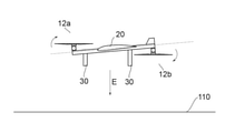
- FIG. 9 is a side view of the flying object of FIG.
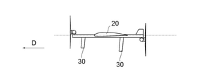
- FIG. 21 is a side view of the flying object of FIG. 21 in the landing mode.
- FIG. 21 is a top view of the flying object of FIG. 21 in the landing mode.
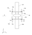
- It is a top view in the landing mode of the configuration example of the flying object according to the present invention.
- It is a side view when the conventional aircraft is cruising.
- It is a side view when the aircraft of FIG. 25 is landing.
- It is a top view when the aircraft of FIG. 25 is landing.
- the flying object according to the embodiment of the present invention has the following configurations.
- the main wing has a configuration in which the lift generated by the main wing during landing is reduced as compared with the lift generated by the main wing during cruising.
- [Item 2] The main wing is tilted forward and fixed to the flight unit.
- the flying object according to item 1 characterized in that.
- the flying object according to item 1 characterized in that.
- the rotors are connected at an angle that produces propulsion and lift during cruising.
- the rotor blades are connected at an angle that generates propulsive force during cruising.
- the flight unit is configured so that the rotor does not interfere with the flight unit or the main wing during landing.
- the main wing is connected to the flight unit via a rotation shaft.
- the main wing has a configuration in which the angle with respect to the flight portion is tilted forward about the rotation axis at the time of landing as compared with the time of cruising.
- the flying object according to item 1 characterized in that.
- the main wing is further connected to the flight portion via a support member and a spring.
- the spring has a configuration in which the support by the support member is released at the time of landing, so that the angle of the main wing with respect to the flight portion is tilted forward about the rotation axis as compared with the time of cruising.
- the main wing is configured to lean forward or backward at an angle of attack that causes a stall in an emergency crash.
- the wing further comprises a moving blade that deploys above the wing upon landing.
- the aircraft body 100 is an aircraft body (VTOL) capable of vertical takeoff and landing.
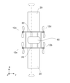
- the flying object 100 includes a plurality of rotary wing portions 12 composed of at least elements such as a propeller 10 and a motor 11 and a main wing 20 for flying.
- the main wing 20 is connected to a flight portion including a rotary wing portion 12 and a main body portion 60.
- the aircraft body 100 has a landing gear 30 that comes into contact with the ground at the time of landing.
- the illustrated flying object 100 is drawn in a simplified manner for the sake of facilitating the explanation of the structure of the present invention. There is.
- the rotary wing portion 12 is connected to the flying object 100 so as to be tiltable, and in the vertical takeoff, hovering, and vertical landing modes, the rotary shaft 40 of the rotary wing descends upward, and in the cruising mode, the rotary wing portion 12 rotates.
- the rotation axis 40 of the wing is tilted forward from the vertical landing mode to propel in the horizontal direction. It is desirable that the flying object 100 is equipped with energy (for example, a secondary battery, a fuel cell, fossil fuel, etc.) for operating a plurality of rotary blade portions 12.
- the main wing 20 can generate lift that assists the flight of the flying object 100. Further, the main wing 20 may be provided with a moving blade, if necessary.
- the landing gear 30 is provided with a ground contact portion that comes into contact with the ground, and may be provided with a damper or the like that cushions the impact when landing or placing an air vehicle.
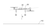
- the direction of arrow D (-Y direction) in the figure is the forward direction
- arrow E is the downward direction (-Z direction) (details will be described later).
- Front-back direction + Y direction and -Y direction
- vertical direction or vertical direction
- left-right direction or horizontal direction
- traveling direction forward
- Retreat direction or horizontal direction
- traveling direction forward
- retreat direction or + Y direction
- ascending direction upward
- descending direction downward
- the propellers 10 to 10d rotate by receiving the output from the motors 11 to 11d.
- the rotation of the propeller 10 generates a propulsive force for taking off the flying object 100 from the starting point, moving it, and landing it at the destination.
- the propeller 10 can rotate to the right, stop, and rotate to the left.
- the propeller 10 included in the flying object 100 of the present invention has one or more blades. Any number of blades (rotors) (eg, 1, 2, 3, 4, or more blades) may be used. Further, the shape of the blade can be any shape such as a flat shape, a curved shape, a twisted shape, a tapered shape, or a combination thereof. The shape of the blade can be changed (for example, expansion / contraction, folding, bending, etc.). The blades may be symmetrical (having the same upper and lower surfaces) or asymmetric (having different shaped upper and lower surfaces). The blades can be formed into an air wheel, wing, or geometry suitable for generating dynamic aerodynamic forces (eg, lift, thrust) as the blades move through the air. The geometry of the blades can be appropriately selected to optimize the dynamic air characteristics of the blades, such as increasing lift and thrust and reducing drag.
- rotors e. 1, 2, 3, 4, or more blades
- shape of the blade can be any shape such as a flat shape
- the propeller included in the flying object of the present invention may have a fixed pitch, a variable pitch, or a mixture of a fixed pitch and a variable pitch, but the propeller is not limited to this.
- the motors 11a to 11d cause rotation of the propellers 10 to 10d
- the drive unit can include an electric motor, an engine, or the like.
- the blades are driveable by the motor and rotate around the axis of rotation of the motor (eg, the long axis of the motor).
- All the blades can rotate in the same direction, and can also rotate independently. Some of the blades rotate in one direction and the other blades rotate in the other direction.
- the blades can all rotate at the same rotation speed, or can rotate at different rotation speeds.
- the rotation speed can be automatically or manually determined based on the dimensions (for example, size, weight) and control state (speed, moving direction, etc.) of the moving body.
- the flight body 100 determines the rotation speed and flight angle of each motor according to the wind speed and the wind direction by a flight controller, a radio, or the like. As a result, the flying object can move ascending / descending, accelerating / decelerating, and changing direction.
- the flight body 100 can perform autonomous flight according to routes and rules set in advance or during flight, and flight by maneuvering using a radio.
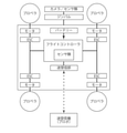
- the above-mentioned flying object 100 has a functional block shown in FIG.
- the functional block in FIG. 2 has a minimum reference configuration.
- the flight controller is a so-called processing unit.
- the processing unit can have one or more processors such as a programmable processor (eg, a central processing unit (CPU)).
- the processing unit has a memory (not shown), and the memory can be accessed.
- the memory stores the logic, code, and / or program instructions that the processing unit can execute to perform one or more steps.
- the memory may include, for example, a separable medium such as an SD card or random access memory (RAM) or an external storage device.
- the data acquired from the cameras and sensors may be directly transmitted and stored in the memory. For example, still image / moving image data taken by a camera or the like is recorded in the built-in memory or an external memory.
- the processing unit includes a control module configured to control the state of the rotorcraft.
- the control module adjusts the spatial arrangement, velocity, and / or acceleration of a rotorcraft with 6 degrees of freedom (translation x, y and z, and rotational motion ⁇ x , ⁇ y and ⁇ z ).
- the control module can control one or more of the states of the mounting unit and the sensors.
- the processing unit is capable of communicating with a transmitter / receiver configured to transmit and / or receive data from one or more external devices (eg, terminals, display devices, or other remote controls).
- the transmitter / receiver can use any suitable communication means such as wired communication or wireless communication.
- the transmitter / receiver uses one or more of a local area network (LAN), wide area network (WAN), infrared, wireless, WiFi, point-to-point (P2P) network, telecommunications network, cloud communication, and the like. be able to.
- the transmitter / receiver can transmit and / or receive one or more of data acquired by sensors, processing results generated by a processing unit, predetermined control data, user commands from a terminal or a remote controller, and the like. ..
- Sensors according to this embodiment may include inertial sensors (acceleration sensors, gyro sensors), GPS sensors, proximity sensors (eg, riders), or vision / image sensors (eg, cameras).
- inertial sensors acceleration sensors, gyro sensors
- GPS sensors GPS sensors
- proximity sensors eg, riders
- vision / image sensors eg, cameras
- the flying object 100 in the present invention uses not only the propulsive force generated by the rotary wing portion 12 but also the lift generated by the main wing 20 in the cruising mode, thereby achieving fuel efficiency during cruising. Can be expected to improve.
- the wing 20 Since the wing 20 does not generate lift without air flow, it is unlikely that the lift generated by the wing 20 will affect landing if there is no wind or a slight wind, but it is always in the actual landing environment. It is difficult to make it windless or breeze.
- the main wing 20 in order to perform stable landing even in an environment affected by wind such as outdoors and to enable landing in a strong wind that is difficult to land with a conventional aircraft, the main wing 20 is in the landing mode.
- the lift generated by the wing 20 is set to be smaller than the lift generated by the main wing 20 during level flight.
- the lift generated by the main wing 20 is reduced in the landing mode.
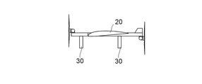
- the angle of attack 21 of the main wing is fixed to the flight unit at an angle that tilts in the negative direction in the landing mode rather than in the cruising mode.
- the tilt angle of the rotary blade portion 12 it is necessary to set the tilt angle of the rotary blade portion 12 to a predetermined angle so that the angle of the rotary shaft 40 of the rotary blade in the cruising mode becomes an appropriate angle.
- the tilt angle of the rotary wing portion 12 in FIGS. 5 and 6 is 25 degrees
- the tilt angle of the rotary wing portion 12 in FIGS. 1 and 3-4 is 90 degrees
- the main wing 20 is the flight portion.
- the tilt angle is 90 when the rotary shaft 40 is substantially vertically upward in the landing mode and the angle of attack of the main wing 20 is in the negative direction as compared with the cruise mode. The angle exceeds the degree.
- the shape may be such that the propeller 10 does not interfere with the main wing or the like.
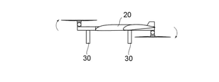
- the rotary wing portion 12 included in the aircraft 100 may have the propeller 10 in the cruising mode and the landing mode interfering with the frame, the arm, the main wing, etc., depending on the mounting position and the tilt angle when the aircraft is displaced to the landing mode. be.
- the frame or arm may have a curved shape (bending, bending, etc.), and as shown in FIGS. 9 and 10, for example, a part of the frame or arm may be provided on the installation side of the propeller 10.
- the shape may be staggered.
- the motor mount (not shown) may be raised.
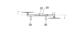
- the main wing 20 included in the flying object 100 according to the second embodiment has a flight unit in a negative angle of attack direction in order to reduce the lift generated by the main wing 20 in the landing mode.
- the connection angle with may be displaced.
- the rotation shaft 22 By providing the rotation shaft 22 at the connection portion between the main wing 20 and the flight portion, the angle of attack 21 of the main wing can be changed. It is desirable that the rotating shaft 22 has strength enough to withstand flight and takeoff and landing, and is lightweight. For example, plastics, metals, shafts such as FRP, pipes, bearings, and the like can be selected and used. These materials may be the same material as the frame or arm included in the flight portion, or may be different materials.
- the angle of attack 21 of the main wing 20 is changed by lowering the load 50 with the load 50 and a part of the main wing 20 connected to each other.
- the angle is once changed to the landing mode. It is desirable to have a configuration in which the fixing of the main wing 20 can be released so that the operation of returning the main wing 20 to the cruising mode can be performed by an external action such as a human hand or a maintenance robot. This can be expected to simplify and reduce the weight of the mechanism provided in the flying object 100.
- the main wing 20 is connected to the flight portion via the rotation shaft 22, and the main wing 20 is attached so as to connect the front side of the main wing 20 and the lower portion of the flight portion.
- the tension spring 24 By the force of the tension spring 24, it is always pulled so as to be at the angle in the landing mode.
- the main wing In the cruising mode, the main wing is fixed in posture against the force of the spring 24 by a support member 23 such as a pin, and is held so that the angle of attack does not tilt in the negative direction from a predetermined angle.
- the pin 23 is pulled out from the main wing 20 by a servo or the like, so that the angle of the main wing 20 changes to a negative angle of attack according to the force of the spring 24.
- the mechanism that shifts the connection angle of the main wing 20 to the flight unit in the negative angle of attack direction not only stabilizes the landing when the flight object lands in normal times, but also limits the crash range when the flight object 100 fails. , Allows for emergency landing.
- the angle of attack of the main wing 20 during flight is set to a negative angle of attack than the zero lift angle, and by actively stalling, the altitude of the aircraft 100 is rapidly lowered and the aircraft is forced to crash.
- the point where the abnormality occurred in the flight object 100 is a suitable place as an emergency crash point (area without a house, on the water, etc.)
- the damage on the house or due to the fall of the aircraft will be enormous. It is important to crash the aircraft more quickly before it moves to its place.
- the aircraft will fall by gliding with the main wing 20 and switching to the emergency crash mode above the point suitable for falling. It is possible to prevent damage caused by. Further, when the flying object falls, it is possible to further reduce the influence on the falling point by further using a means for reducing the falling speed such as a parachute.
- the stall In the emergency landing mode, if the negative or positive angle of attack of the main wing is increased to an angle that exceeds the stall angle, the stall can be entered and the flight speed can be expected to decrease due to the increase in the resistance of the main wing 20.
- the main wing 20 included in the flying object 100 according to the third embodiment includes a moving blade 25 as a mechanism for reducing lift, and the moving blade 25 causes the main wing to move. It is possible to reduce the lift generated by 20.
- a vertical landing aircraft for example, Harrier, F-35B, etc.
- a flap high lift device
- the flying object 100 according to the present invention has a configuration capable of stable landing by reducing the lift obtained in the landing mode, the moving blades 25 can be deployed upward from the cruising mode to obtain the main wing 20. Obtain the effect of reducing the lift generated.
- the drag force also increases as a side effect.
- the increase in drag causes the flying object 100 to be swept away by the headwind and the accuracy of landing is lowered, it is preferable that the increase in drag is small. Therefore, it is necessary to consider the balance between the decrease in lift and the increase in drag.
- the main wing 20 may be deformed by using a variable swept wing or a variable forward wing mechanism as shown in FIGS. 21 to 23, or as shown in FIG. 24. Therefore, there is a method of providing a mechanism such as a fan 26 for generating an upward wake in the main wing 20 and rotating the fan 26 in the landing mode.
- the above-mentioned configuration of the flying object in each embodiment can be implemented by combining a plurality of them. It is desirable to consider the configuration as appropriate according to the cost of manufacturing the aircraft and the environment and characteristics of the place where the aircraft is operated.
Landscapes
- Engineering & Computer Science (AREA)
- Aviation & Aerospace Engineering (AREA)
- Mechanical Engineering (AREA)
- Remote Sensing (AREA)
- Chemical & Material Sciences (AREA)
- Combustion & Propulsion (AREA)
- Toys (AREA)
Priority Applications (7)
| Application Number | Priority Date | Filing Date | Title |
|---|---|---|---|
| PCT/JP2020/033761 WO2022049764A1 (ja) | 2020-09-07 | 2020-09-07 | 飛行体 |
| US18/042,446 US12286250B2 (en) | 2020-09-07 | 2020-09-07 | Flying vehicle |
| EP20952498.2A EP4212430A4 (en) | 2020-09-07 | 2020-09-07 | FLYING VEHICLE |
| CN202080103731.2A CN116096634B (zh) | 2020-09-07 | 2020-09-07 | 飞行体 |
| JP2021513484A JPWO2022049764A1 (https=) | 2020-09-07 | 2020-09-07 | |
| JP2021129679A JP6970479B1 (ja) | 2020-09-07 | 2021-08-06 | 飛行体 |
| US19/096,288 US20250229917A1 (en) | 2020-09-07 | 2025-03-31 | Flying vehicle |
Applications Claiming Priority (1)
| Application Number | Priority Date | Filing Date | Title |
|---|---|---|---|
| PCT/JP2020/033761 WO2022049764A1 (ja) | 2020-09-07 | 2020-09-07 | 飛行体 |
Related Child Applications (2)
| Application Number | Title | Priority Date | Filing Date |
|---|---|---|---|
| US18/042,446 A-371-Of-International US12286250B2 (en) | 2020-09-07 | 2020-09-07 | Flying vehicle |
| US19/096,288 Division US20250229917A1 (en) | 2020-09-07 | 2025-03-31 | Flying vehicle |
Publications (1)
| Publication Number | Publication Date |
|---|---|
| WO2022049764A1 true WO2022049764A1 (ja) | 2022-03-10 |
Family
ID=80490854
Family Applications (1)
| Application Number | Title | Priority Date | Filing Date |
|---|---|---|---|
| PCT/JP2020/033761 Ceased WO2022049764A1 (ja) | 2020-09-07 | 2020-09-07 | 飛行体 |
Country Status (5)
| Country | Link |
|---|---|
| US (2) | US12286250B2 (https=) |
| EP (1) | EP4212430A4 (https=) |
| JP (1) | JPWO2022049764A1 (https=) |
| CN (1) | CN116096634B (https=) |
| WO (1) | WO2022049764A1 (https=) |
Cited By (1)
| Publication number | Priority date | Publication date | Assignee | Title |
|---|---|---|---|---|
| WO2025197128A1 (ja) * | 2024-03-18 | 2025-09-25 | 株式会社エアロネクスト | 飛行体および飛行体の制御方法、プログラム |
Families Citing this family (4)
| Publication number | Priority date | Publication date | Assignee | Title |
|---|---|---|---|---|
| JP6952380B1 (ja) * | 2020-08-11 | 2021-10-20 | 株式会社エアロネクスト | 移動体 |
| JPWO2022049764A1 (https=) * | 2020-09-07 | 2022-03-10 | ||
| JP7838755B2 (ja) * | 2022-03-29 | 2026-04-01 | 株式会社石川エナジーリサーチ | 飛行装置 |
| JP2025064304A (ja) * | 2023-10-06 | 2025-04-17 | 本田技研工業株式会社 | 飛行体制御装置、飛行体、飛行体の制御方法、プログラム及びコンピュータにより読み取り可能な非一過性の記憶媒体 |
Citations (5)
| Publication number | Priority date | Publication date | Assignee | Title |
|---|---|---|---|---|
| JPH0577789A (ja) * | 1991-09-20 | 1993-03-30 | Kawasaki Heavy Ind Ltd | 垂直離着陸航空機 |
| JP2009078745A (ja) * | 2007-09-27 | 2009-04-16 | Japan Aerospace Exploration Agency | 電動垂直離着陸機 |
| JP2009234551A (ja) * | 2008-03-26 | 2009-10-15 | Kenta Yasuda | 主翼取り付け角変更装置を備えた垂直離着陸航空機 |
| US10131426B2 (en) | 2013-08-29 | 2018-11-20 | Airbus Defence and Space GmbH | Aircraft capable of vertical take-off |
| JP2019018623A (ja) * | 2017-07-12 | 2019-02-07 | 倫文 木原 | 無人飛行体 |
Family Cites Families (111)
| Publication number | Priority date | Publication date | Assignee | Title |
|---|---|---|---|---|
| US1786545A (en) * | 1925-04-29 | 1930-12-30 | Noeggerath Jacob Emil | Aeroplane for horizontal and vertical flight |
| US2230370A (en) * | 1937-03-04 | 1941-02-04 | Alan Muntz & Co Ltd | Aircraft |
| US2437330A (en) * | 1944-01-24 | 1948-03-09 | Alexander S Mullgardt | Variable incidence wing control for aircraft of the rotaly wing or airplane sustained type |
| US2989269A (en) * | 1959-04-06 | 1961-06-20 | Bel John P Le | Convertible aircraft |
| US3181810A (en) * | 1961-02-27 | 1965-05-04 | Curtiss Wright Corp | Attitude control system for vtol aircraft |
| US3117745A (en) * | 1961-04-27 | 1964-01-14 | Kaman Aircraft Corp | Vtol/stol aircraft |
| US3159361A (en) * | 1962-02-14 | 1964-12-01 | Carl W Weiland | Aircraft |
| US4982914A (en) * | 1966-05-18 | 1991-01-08 | Karl Eickmann | Aircraft with a plurality of propellers, a pipe structure for thereon holdable wings, for vertical take off and landing |
| GB1322169A (en) * | 1969-07-23 | 1973-07-04 | Kisovec A V | Convertiplanes |
| US3592412A (en) * | 1969-10-03 | 1971-07-13 | Boeing Co | Convertible aircraft |
| US4149688A (en) * | 1976-10-01 | 1979-04-17 | Aereon Corporation | Lifting body aircraft for V/STOL service |
| US6292491B1 (en) * | 1998-08-25 | 2001-09-18 | Cisco Technology, Inc. | Distributed FIFO queuing for ATM systems |
| US6655631B2 (en) * | 2000-07-28 | 2003-12-02 | John Frederick Austen-Brown | Personal hoverplane with four tiltmotors |
| US20030062443A1 (en) * | 2001-10-02 | 2003-04-03 | Joseph Wagner | VTOL personal aircraft |
| AUPS330502A0 (en) * | 2002-06-28 | 2002-07-25 | Kusic, Tom | Tandem powered power tilting aircraft - june 2002 |
| US9493235B2 (en) * | 2002-10-01 | 2016-11-15 | Dylan T X Zhou | Amphibious vertical takeoff and landing unmanned device |
| US6843447B2 (en) * | 2003-01-06 | 2005-01-18 | Brian H. Morgan | Vertical take-off and landing aircraft |
| US20050230519A1 (en) * | 2003-09-10 | 2005-10-20 | Hurley Francis X | Counter-quad tilt-wing aircraft design |
| US7857254B2 (en) * | 2004-12-22 | 2010-12-28 | Aurora Flight Sciences Corporation | System and method for utilizing stored electrical energy for VTOL aircraft thrust enhancement and attitude control |
| US7159817B2 (en) * | 2005-01-13 | 2007-01-09 | Vandermey Timothy | Vertical take-off and landing (VTOL) aircraft with distributed thrust and control |
| WO2006113877A2 (en) * | 2005-04-20 | 2006-10-26 | Lugg Richard H | Hybrid jet/electric vtol aircraft |
| US8720814B2 (en) * | 2005-10-18 | 2014-05-13 | Frick A. Smith | Aircraft with freewheeling engine |
| US8152096B2 (en) * | 2005-10-18 | 2012-04-10 | Smith Frick A | Apparatus and method for vertical take-off and landing aircraft |
| US7874514B2 (en) * | 2006-06-05 | 2011-01-25 | Lockheed Martin Corporation | Amphibious aircraft |
| EP2097317A1 (en) * | 2006-11-02 | 2009-09-09 | Severino Manuel Oliveira Raposo | System and process of vector propulsion with independent control of three translation and three rotation axis |
| US8453962B2 (en) * | 2007-02-16 | 2013-06-04 | Donald Orval Shaw | Modular flying vehicle |
| EP2152576A2 (en) * | 2007-05-02 | 2010-02-17 | Urban Aeronautics Ltd. | Control flows and forces in vtol vehicles |
| US20110001020A1 (en) * | 2009-07-02 | 2011-01-06 | Pavol Forgac | Quad tilt rotor aerial vehicle with stoppable rotors |
| US20110042508A1 (en) * | 2009-08-24 | 2011-02-24 | Bevirt Joeben | Controlled take-off and flight system using thrust differentials |
| US8733690B2 (en) * | 2009-08-24 | 2014-05-27 | Joby Aviation, Inc. | Lightweight vertical take-off and landing aircraft and flight control paradigm using thrust differentials |
| US8282036B2 (en) * | 2009-12-15 | 2012-10-09 | Funck Stephen H | Multi wing aircraft |
| WO2012141736A1 (en) * | 2010-10-06 | 2012-10-18 | Shaw Donlad Orval | Aircraft with wings and movable propellers |
| US8702031B2 (en) * | 2011-06-20 | 2014-04-22 | Richard David Morris | VTOL twin fuselage amphibious aircraft with tilt-center wing, engine and rotor |
| TWI538852B (zh) * | 2011-07-19 | 2016-06-21 | 季航空股份有限公司 | 個人飛機 |
| US9120560B1 (en) * | 2011-10-13 | 2015-09-01 | Latitude Engineering, LLC | Vertical take-off and landing aircraft |
| SG194257A1 (en) * | 2012-04-26 | 2013-11-29 | Yik Hei Sia | Power generating windbags and water-bags |
| CN203005747U (zh) * | 2012-10-30 | 2013-06-19 | 武卫平 | 倾转旋翼飞机 |
| US9499263B2 (en) * | 2013-03-14 | 2016-11-22 | Curtis Youngblood | Multi-rotor aircraft |
| US9481457B2 (en) * | 2014-04-02 | 2016-11-01 | Sikorsky Aircraft Corporation | Vertical take-off and landing aircraft with variable wing geometry |
| US9611038B2 (en) * | 2014-06-03 | 2017-04-04 | Working Drones, Inc. | Mobile computing device-based guidance navigation and control for unmanned aerial vehicles and robotic systems |
| US9475585B2 (en) * | 2014-06-25 | 2016-10-25 | The Boeing Company | Tilt-rotor vertical-lift aircraft |
| WO2016009376A1 (en) * | 2014-07-18 | 2016-01-21 | Pegasus Universal Aerospace (Pty) Ltd. | Vertical take-off and landing aircraft |
| US10648455B2 (en) * | 2014-10-14 | 2020-05-12 | Twingtec Ag | Flying apparatus |
| WO2016068767A1 (en) * | 2014-10-30 | 2016-05-06 | Acc Innovation Ab | Multi-rotor aerial vehicle |
| US11034443B2 (en) * | 2015-06-12 | 2021-06-15 | Sunlight Aerospace Inc. | Modular aircraft assembly for airborne and ground transport |
| US9714090B2 (en) * | 2015-06-12 | 2017-07-25 | Sunlight Photonics Inc. | Aircraft for vertical take-off and landing |
| WO2017132304A1 (en) * | 2016-01-29 | 2017-08-03 | JG Entrepreneurial Enterprises LLC | Vehicles and systems for weather modification |
| CN105711831B (zh) * | 2016-04-25 | 2018-03-06 | 长江大学 | 垂直起降的固定翼无人机 |
| KR101838796B1 (ko) * | 2016-04-27 | 2018-03-14 | 한국항공우주연구원 | 기울기 제어 날개를 가지는 비행체 |
| US10981661B2 (en) * | 2016-07-01 | 2021-04-20 | Textron Innovations Inc. | Aircraft having multiple independent yaw authority mechanisms |
| US10301016B1 (en) * | 2016-08-09 | 2019-05-28 | Vimana, Inc. | Stabilized VTOL flying apparatus and aircraft |
| US10252796B2 (en) * | 2016-08-09 | 2019-04-09 | Kitty Hawk Corporation | Rotor-blown wing with passively tilting fuselage |
| US10384774B2 (en) * | 2016-09-08 | 2019-08-20 | General Electric Company | Tiltrotor propulsion system for an aircraft |
| US10392106B2 (en) * | 2016-09-08 | 2019-08-27 | General Electric Company | Tiltrotor propulsion system for an aircraft |
| US10384773B2 (en) * | 2016-09-08 | 2019-08-20 | General Electric Company | Tiltrotor propulsion system for an aircraft |
| US10252797B2 (en) * | 2016-09-08 | 2019-04-09 | General Electric Company | Tiltrotor propulsion system for an aircraft |
| US10399673B1 (en) * | 2016-10-24 | 2019-09-03 | Kitty Hawk Corporation | Integrated float-wing |
| US10370082B2 (en) * | 2016-12-27 | 2019-08-06 | Korea Advanced Institute Of Science And Technology | Aircraft capable of vertical take-off and landing, vertical and horizontal flight and on-air energy generation |
| US10392107B2 (en) * | 2016-12-27 | 2019-08-27 | Korea Advanced Institute Of Science And Technology | Aerial vehicle capable of vertical take-off and landing, vertical and horizontal flight and on-air energy generation |
| US10421540B1 (en) * | 2017-03-02 | 2019-09-24 | Bell Textron Inc. | Tiltrotor aircraft having optimized hover capabilities |
| US11731772B2 (en) * | 2017-03-02 | 2023-08-22 | Textron Innovations Inc. | Hybrid propulsion drive train system for tiltrotor aircraft |
| US10252798B2 (en) * | 2017-04-27 | 2019-04-09 | Pterodynamics | Vertical takeoff and landing airframe |
| AU2018266343B2 (en) * | 2017-05-08 | 2023-09-21 | Insitu, Inc. | Modular aircraft with vertical takeoff and landing capability |
| USD870638S1 (en) * | 2017-05-19 | 2019-12-24 | Hg Robotics Company Limited | Unmanned aerial vehicle |
| US11059598B2 (en) * | 2017-06-01 | 2021-07-13 | Moog Inc. | Auxiliary power system for rotorcraft with folding propeller arms and crumple zone loading gear |
| JP6425323B1 (ja) * | 2017-07-27 | 2018-11-21 | 株式会社辰巳菱機 | 浮遊型移動装置 |
| WO2019036011A1 (en) * | 2017-08-18 | 2019-02-21 | Verdego Aero, Inc. | VERTICAL TAKE-OFF AND LANDING AIRCRAFT CONFIGURATION |
| USD862285S1 (en) * | 2017-08-25 | 2019-10-08 | MerchSource, LLC | Drone |
| GB2566095B (en) * | 2017-09-04 | 2019-10-02 | Artemis Intelligent Power Ltd | Hydraulic multi-rotor aerial vehicle |
| USD864083S1 (en) * | 2017-10-09 | 2019-10-22 | Guangdong Shiji Technology Co., Ltd | Quadcopter |
| USD864082S1 (en) * | 2017-10-09 | 2019-10-22 | Guangdong Shiji Technology Co., Ltd | Quadcopter |
| WO2019074859A2 (en) * | 2017-10-11 | 2019-04-18 | Purdue Research Foundation | HYDROSTATIC PROPULSION SYSTEM WITH DISPLACEMENT CONTROL FOR MULTI-ROTOR VERTICAL TAKEOFF AND LANDING AIRCRAFT |
| USD858352S1 (en) * | 2017-10-30 | 2019-09-03 | Shenzhen Valuelink E-Commerce Co., Ltd. | Drone |
| USD858353S1 (en) * | 2017-10-30 | 2019-09-03 | Shenzhen Valuelink E-Commerce Co., Ltd. | Drone |
| US10836481B2 (en) * | 2017-11-09 | 2020-11-17 | Bell Helicopter Textron Inc. | Biplane tiltrotor aircraft |
| US10696391B2 (en) * | 2017-11-16 | 2020-06-30 | Textron Innovations Inc. | Extended range quad tiltrotor aircraft |
| US10752352B2 (en) * | 2017-12-07 | 2020-08-25 | Textron Innovations Inc. | Dual rotor propulsion systems for tiltrotor aircraft |
| USD906170S1 (en) * | 2018-02-13 | 2020-12-29 | Skydio, Inc. | Unmanned aerial vehicle |
| USD864022S1 (en) * | 2018-03-30 | 2019-10-22 | Shenzhen Valuelink E-Commerce Co., Ltd. | Unmanned aerial vehicle |
| USD860047S1 (en) * | 2018-04-08 | 2019-09-17 | Shenzhen Valuelink E-Commerce Co., Ltd. | Unmanned aerial vehicle |
| WO2019210128A2 (en) * | 2018-04-27 | 2019-10-31 | Aai Corporation | Variable pitch rotor assembly for electrically driven vectored thrust aircraft applications |
| USD873175S1 (en) * | 2018-05-23 | 2020-01-21 | Shenzhen Hubsan Technology Co., Ltd. | Drone |
| US11827347B2 (en) * | 2018-05-31 | 2023-11-28 | Joby Aero, Inc. | Electric power system architecture and fault tolerant VTOL aircraft using same |
| EP3581490B1 (en) * | 2018-06-13 | 2021-01-13 | AIRBUS HELICOPTERS DEUTSCHLAND GmbH | A multirotor aircraft with a thrust producing unit that comprises an aerodynamically optimized shrouding |
| DE102018116167B4 (de) * | 2018-07-04 | 2024-03-21 | Dr. Ing. H.C. F. Porsche Aktiengesellschaft | Luftfahrzeug |
| US11926429B2 (en) * | 2018-07-04 | 2024-03-12 | Dr. Ing. H.C. F. Porsche Aktiengesellschaft | Aircraft having cooling system for distributing heat transfer liquid to different regions of aircraft |
| US11603193B2 (en) * | 2018-07-16 | 2023-03-14 | Donghyun Kim | Aircraft convertible between fixed-wing and hovering orientations |
| US20200031458A1 (en) * | 2018-07-25 | 2020-01-30 | Mark E Strauss | Unmanned Aerial Vehicle with Thrust Decoupling, Active Wing Loading, Omnidirectional Lift Control and/or Vibration Management |
| WO2020061085A1 (en) * | 2018-09-17 | 2020-03-26 | Joby Aero, Inc. | Aircraft control system |
| EP3656669B1 (en) * | 2018-11-26 | 2021-01-13 | AIRBUS HELICOPTERS DEUTSCHLAND GmbH | A vertical take-off and landing multirotor aircraft with at least eight thrust producing units |
| JP7401545B2 (ja) * | 2018-12-07 | 2023-12-19 | ジョビー エアロ インク | 回転翼とその設計方法 |
| WO2020132332A1 (en) * | 2018-12-19 | 2020-06-25 | Joby Aero, Inc. | Vehicle navigation system |
| EP3906190A2 (en) * | 2018-12-31 | 2021-11-10 | Polarity Mobility Av Ltd. | Vtol aircraft |
| CN109911179B (zh) * | 2019-03-13 | 2022-11-04 | 南京灵龙旋翼无人机系统研究院有限公司 | 一种垂直起降和高速飞行的推进式旋转机翼飞机及其控制方法 |
| US11230384B2 (en) * | 2019-04-23 | 2022-01-25 | Joby Aero, Inc. | Vehicle cabin thermal management system and method |
| US10988248B2 (en) * | 2019-04-25 | 2021-04-27 | Joby Aero, Inc. | VTOL aircraft |
| US11643199B2 (en) * | 2019-05-10 | 2023-05-09 | Eve Uam, Llc | Vertical take-off and landing (VTOL) aircraft |
| JP7634484B2 (ja) * | 2019-05-21 | 2025-02-21 | ジョビー エアロ インク | 固定前方傾斜ロータを使用して剛体翼の空気力学をシミュレートする垂直離着陸航空機 |
| CN114375276B (zh) * | 2019-10-09 | 2024-12-24 | 小鹰公司 | 具有前掠翼的短距起降载具 |
| CN110789710A (zh) * | 2019-11-19 | 2020-02-14 | 江富余 | 负弯度翼型机身制动诱导差速式多旋翼直升机 |
| US11554855B2 (en) * | 2019-12-31 | 2023-01-17 | Textron Innovations Inc. | System and method for protection against vortex ring state |
| JPWO2022049764A1 (https=) * | 2020-09-07 | 2022-03-10 | ||
| IL302561B2 (en) * | 2020-11-30 | 2025-12-01 | Efix Aviation Ltd | Rotorcraft |
| US11772773B2 (en) * | 2021-01-04 | 2023-10-03 | Aurora Flight Sciences Corporation, a subsidiary of The Boeing Company | Aircraft and related methods |
| US11919631B2 (en) * | 2021-02-08 | 2024-03-05 | Archer Aviation, Inc. | Vertical take-off and landing aircraft with aft rotor tilting |
| US11618338B2 (en) * | 2021-02-16 | 2023-04-04 | Archer Aviation, Inc. | Systems and methods for managing a network of electric aircraft batteries |
| US12234011B2 (en) * | 2021-08-02 | 2025-02-25 | Gerald E. Brown | Convertiplane with stopped rotors, and repositionable rotor blades |
| US11530028B1 (en) * | 2021-08-19 | 2022-12-20 | Beta Air, Llc | Systems and methods for the autonomous transition of an electric vertical takeoff and landing aircraft |
| US20230174225A1 (en) * | 2021-12-03 | 2023-06-08 | This Is Engineering Inc. | Multi-rotor aircrafts with passively tiltable rotor groups and methods of making and using the same |
| US20230202652A1 (en) * | 2021-12-23 | 2023-06-29 | Octofan Sas | Drone |
| US11787551B1 (en) * | 2022-10-06 | 2023-10-17 | Archer Aviation, Inc. | Vertical takeoff and landing aircraft electric engine configuration |
-
2020
- 2020-09-07 JP JP2021513484A patent/JPWO2022049764A1/ja not_active Ceased
- 2020-09-07 WO PCT/JP2020/033761 patent/WO2022049764A1/ja not_active Ceased
- 2020-09-07 US US18/042,446 patent/US12286250B2/en active Active
- 2020-09-07 EP EP20952498.2A patent/EP4212430A4/en active Pending
- 2020-09-07 CN CN202080103731.2A patent/CN116096634B/zh active Active
-
2025
- 2025-03-31 US US19/096,288 patent/US20250229917A1/en active Pending
Patent Citations (5)
| Publication number | Priority date | Publication date | Assignee | Title |
|---|---|---|---|---|
| JPH0577789A (ja) * | 1991-09-20 | 1993-03-30 | Kawasaki Heavy Ind Ltd | 垂直離着陸航空機 |
| JP2009078745A (ja) * | 2007-09-27 | 2009-04-16 | Japan Aerospace Exploration Agency | 電動垂直離着陸機 |
| JP2009234551A (ja) * | 2008-03-26 | 2009-10-15 | Kenta Yasuda | 主翼取り付け角変更装置を備えた垂直離着陸航空機 |
| US10131426B2 (en) | 2013-08-29 | 2018-11-20 | Airbus Defence and Space GmbH | Aircraft capable of vertical take-off |
| JP2019018623A (ja) * | 2017-07-12 | 2019-02-07 | 倫文 木原 | 無人飛行体 |
Cited By (1)
| Publication number | Priority date | Publication date | Assignee | Title |
|---|---|---|---|---|
| WO2025197128A1 (ja) * | 2024-03-18 | 2025-09-25 | 株式会社エアロネクスト | 飛行体および飛行体の制御方法、プログラム |
Also Published As
| Publication number | Publication date |
|---|---|
| US20230331407A1 (en) | 2023-10-19 |
| US20250229917A1 (en) | 2025-07-17 |
| EP4212430A1 (en) | 2023-07-19 |
| EP4212430A4 (en) | 2024-06-26 |
| US12286250B2 (en) | 2025-04-29 |
| JPWO2022049764A1 (https=) | 2022-03-10 |
| CN116096634A (zh) | 2023-05-09 |
| CN116096634B (zh) | 2025-08-22 |
Similar Documents
| Publication | Publication Date | Title |
|---|---|---|
| US10370100B2 (en) | Aerodynamically actuated thrust vectoring devices | |
| US20250229917A1 (en) | Flying vehicle | |
| JP7509427B2 (ja) | 飛行体 | |
| US20230013275A1 (en) | Takeoff and landing system | |
| JP2025061770A (ja) | 飛行体の制御方法 | |
| US12378012B2 (en) | Aerial vehicle | |
| JP6970479B1 (ja) | 飛行体 | |
| CN220640232U (zh) | 飞行器 | |
| JP7770700B2 (ja) | 飛行体の着陸方法、飛行体、情報処理装置、プログラム | |
| US20240199203A1 (en) | Flight body, landing method, and program | |
| CN218258694U (zh) | 飞行体 | |
| CN220948591U (zh) | 飞行体 | |
| US20250002163A1 (en) | Flying object provided with safety device | |
| WO2025197128A1 (ja) | 飛行体および飛行体の制御方法、プログラム | |
| WO2024201841A1 (ja) | 着陸装置、離着陸システムおよび着陸装置の制御方法 |
Legal Events
| Date | Code | Title | Description |
|---|---|---|---|
| ENP | Entry into the national phase |
Ref document number: 2021513484 Country of ref document: JP Kind code of ref document: A |
|
| 121 | Ep: the epo has been informed by wipo that ep was designated in this application |
Ref document number: 20952498 Country of ref document: EP Kind code of ref document: A1 |
|
| NENP | Non-entry into the national phase |
Ref country code: DE |
|
| ENP | Entry into the national phase |
Ref document number: 2020952498 Country of ref document: EP Effective date: 20230411 |
|
| WWG | Wipo information: grant in national office |
Ref document number: 18042446 Country of ref document: US |
|
| WWG | Wipo information: grant in national office |
Ref document number: 202080103731.2 Country of ref document: CN |