WO2022049684A1 - 遠心送風機 - Google Patents
遠心送風機 Download PDFInfo
- Publication number
- WO2022049684A1 WO2022049684A1 PCT/JP2020/033334 JP2020033334W WO2022049684A1 WO 2022049684 A1 WO2022049684 A1 WO 2022049684A1 JP 2020033334 W JP2020033334 W JP 2020033334W WO 2022049684 A1 WO2022049684 A1 WO 2022049684A1
- Authority
- WO
- WIPO (PCT)
- Prior art keywords
- impeller
- centrifugal blower
- bell mouth
- wall surface
- protrusion
- Prior art date
- Legal status (The legal status is an assumption and is not a legal conclusion. Google has not performed a legal analysis and makes no representation as to the accuracy of the status listed.)
- Ceased
Links
Images









Classifications
-
- F—MECHANICAL ENGINEERING; LIGHTING; HEATING; WEAPONS; BLASTING
- F04—POSITIVE - DISPLACEMENT MACHINES FOR LIQUIDS; PUMPS FOR LIQUIDS OR ELASTIC FLUIDS
- F04D—NON-POSITIVE-DISPLACEMENT PUMPS
- F04D29/00—Details, component parts, or accessories
- F04D29/26—Rotors specially for elastic fluids
- F04D29/28—Rotors specially for elastic fluids for centrifugal or helico-centrifugal pumps for radial-flow or helico-centrifugal pumps
Definitions
- the present disclosure relates to a centrifugal blower equipped with a scroll casing provided with a bell mouth.
- the centrifugal blower is equipped with a bell mouth on the surface of the scroll casing that houses the impeller. Noise generated in the scroll casing of the centrifugal blower due to the rotation of the impeller or the operation of the drive motor is radiated to the outside of the scroll casing through the bell mouth.
- the outer peripheral surface of the bell mouth is provided with a plurality of protrusions extending in the direction of the rotation axis of the impeller at intervals in the rotation direction of the impeller, thereby suppressing the re-suction flow and improving the fan efficiency.
- An improved centrifugal blower is disclosed.
- Centrifugal blowers are required to improve not only fan efficiency but also quietness.
- the centrifugal blower disclosed in Patent Document 1 contributes to the improvement of fan efficiency, but no measures have been taken to reduce noise.
- the present disclosure has been made in view of the above, and an object of the present disclosure is to obtain a centrifugal blower that achieves both low noise and high efficiency.
- the centrifugal blower includes a drive motor, an impeller fixed to the motor shaft of the drive motor, and an impeller and blades that rotate around the rotation axis of the motor shaft.
- the inner wall surface of the bell mouth facing the inside of the scroll casing is provided with an undulating portion extending in the rotation direction of the impeller. The undulations are formed on the inner wall surface of the bell mouth by the undulations.
- the centrifugal blower according to the present disclosure has the effect of achieving both low noise and high efficiency.
- FIG. 1 Perspective view of the centrifugal blower according to the first embodiment Sectional drawing of the centrifugal blower which concerns on Embodiment 1.
- Top view of the centrifugal blower according to the first embodiment The figure which shows the fluid analysis result of the internal flow of the centrifugal blower which concerns on Embodiment 1.
- centrifugal blower according to the embodiment will be described in detail below based on the drawings.
- FIG. 1 is a perspective view of the centrifugal blower according to the first embodiment.
- FIG. 2 is a cross-sectional view of the centrifugal blower according to the first embodiment.
- FIG. 2 schematically shows a cross section along the line II-II in FIG.
- the centrifugal blower 1 according to the first embodiment includes a drive motor 10 and an impeller 3 fixed to a motor shaft 11 of the drive motor 10. Further, the centrifugal blower 1 guides the bell mouth 5 that takes air into the impeller 3, the airflow port 6a that blows out the airflow Y2 generated by the impeller 3, and the airflow Y1 generated by the impeller 3 to the outlet 6a.
- the scroll casing 20 is provided with a tongue portion 7 and a casing main body 6 for accommodating the impeller 3.
- the bell mouth 5 has a suction port 4 into which the mainstream Y3 flowing into the impeller 3 from the upstream side flows into the impeller 3, and a large-diameter mouth surface 8 arranged on the upstream side of the mainstream Y3 with respect to the suction port 4.
- the impeller 3 includes a boss portion 9 fixed to the motor shaft 11 and blades 3a installed on the peripheral portion of the boss portion 9.
- a protrusion 12 extending in the rotation direction of the impeller 3 is provided on the wall surface facing the inside of the scroll casing 20 over the entire circumference.
- the protrusion 12 has a rotationally symmetric shape with the rotation shaft 2 of the motor shaft 11 as the central axis.
- the wall surface facing the inside of the scroll casing 20 is referred to as an “inner wall surface”.
- a protrusion 12 extending in the rotation direction of the impeller 3 is provided on the inner wall surface of the bell mouth 5, and the protrusion 12 forms an undulation on the inner wall surface of the bell mouth 5.
- the protrusion 12 extends in the rotation direction of the impeller 3" means that the protrusion 12 has a shape in which the dimension in the rotation direction of the impeller 3 is longer than the dimension in the rotation axis direction of the impeller 3. means.
- the protrusion 12 is an undulation forming portion that forms an undulation on the inner wall surface of the bell mouth 5.
- the undulation of the inner wall surface of the bell mouth 5 is high at the portion of the protrusion 12 which is the undulation forming portion, and is low at the adjacent portion 5a of the inner wall surface of the bell mouth 5 adjacent to the undulation forming portion.
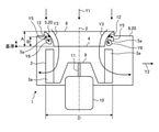
- FIG. 3 is a diagram showing a cross-sectional shape of a bell mouth and a protrusion of the centrifugal blower according to the first embodiment.
- the suction port 4 of the bell mouth 5 as a reference, the distance between the suction port 4 of the bell mouth 5 and the large-diameter mouth surface 8 is defined as the bell mouth distance A, and the suction port 4 of the bell mouth 5 and the suction port 4 of the protrusion 12 are on the side.
- the distance from the end is defined as the protrusion distance B.
- C be the protruding length of the protrusion 12.
- the blade outer diameter of the impeller 3 is D.
- the protrusion 12 is integrated with the bell mouth 5, the shape is based on the fact that the resin is molded with a mold.
- the protrusion length C is the blade outer diameter D in consideration of the effect described later that the protrusion 12 brings while avoiding a sudden change in the plate thickness of the bell mouth 5 when considering the molding of the bell mouth 5 by the resin. It is said to be 1.1% of.
- the protrusion length C of the protrusion 12 is dimensionlessly determined by the blade outer diameter D.
- the tip of the protrusion 12 is not a sharp shape but a rounded shape so as not to cause turbulence of the air flow.
- the mainstream Y3 formed by the rotation of the impeller 3 passes through the bell mouth 5 and is sucked into the scroll casing 20.
- the mainstream Y3 sucked into the scroll casing 20 heads for the outlet 6a.
- the impeller 3 rotates to form secondary flows Y5 and Y6 that flow in a direction different from that of the mainstream Y3.
- a loss occurs inside the centrifugal blower 1 and an increase in noise and a fan. It leads to a decrease in efficiency.
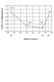
- FIG. 4 is a diagram showing the noise reduction effect of the centrifugal blower according to the first embodiment.
- the horizontal axis of FIG. 4 is a value obtained by dividing the protrusion distance B by the bellmouth distance A.
- B / A 0.85 is synonymous with providing the protrusion 12 at a position of 85% of the bell mouth distance A.
- the vertical axis of FIG. 4 shows the noise reduction effect when compared with the centrifugal blower according to the comparative example not provided with the protrusion 12.
- the path of the secondary flow Y5 flowing in a direction different from that of the mainstream Y3 can be cut off, and the protrusion 12 can be cut off as compared with the case where the protrusion 12 is not provided.
- the secondary flow Y6 is less likely to occur on the downstream side of 12. That is, as compared with the case where the protrusion 12 is not provided, the vortex that causes the turbulence of the airflow is less likely to occur, and the secondary loss due to the turbulence of the airflow is less likely to occur. Further, by providing the protrusion 12, the interference between the vortices is suppressed, so that both low noise and high efficiency can be achieved at the same time.
- FIG. 5 is a plan view of the centrifugal blower according to the first embodiment.
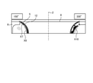
- FIGS. 6 and 7 are diagrams showing the fluid analysis result of the internal flow of the centrifugal blower according to the first embodiment.
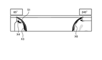
- 8 and 9 are diagrams showing the fluid analysis result of the internal flow of the centrifugal blower according to the comparative example of the first embodiment.
- the fluid analysis results are shown using the second invariant of the velocity gradient tensor, which indicates the strength of the vortex.
- the unit of the second invariant of the velocity gradient tensor is [/ s 2 ].
- the distribution of vortices indicates that the closer the color is to black, the stronger the vortex, and the closer the color is to white, the weaker the vortex.
- the black color is 100000 / s 2 and the white color is 0 / s 2 .
- a strong vortex X5 is formed along the wall surface of the bell mouth 5.
- the range of occurrence is suppressed by the protrusion 12.
- the strong vortex X6 along the wall surface of the bell mouth 51 is formed along the wall surface over a wide range.
- the vortex generated in the vicinity of the bell mouth 5 is a strong vortex X7 and a strong vortex. It is separated from X8 by a protrusion 12.
- the range of generation of the vortex X10 of the centrifugal blower 1 according to the first embodiment including the protrusion 12 is that of the centrifugal blower according to the comparative example not provided with the protrusion 12.
- the centrifugal blower according to the comparative example looks wider than the generation range of the vortex X11, the vortex X12 and the vortex X13, in the centrifugal blower according to the comparative example, three vortices X11, the vortex X12 and the vortex X13 are generated, and the distance between the vortices is short, so that there are a plurality of vortices.
- the vortex is interfering.
- a plurality of strong vortices X11, vortices X12 and vortices X13 are generated on the surface of the inner wall surface of the bell mouth 51 and interfere with each other to have unsteadiness. It is easy to predict that the number of vortices will increase, leading to an increase in noise sources and an increase in energy loss.
- FIG. 10 is a diagram showing a first modification of the centrifugal blower according to the first embodiment.
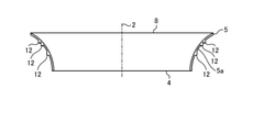
- three protrusions 12 are formed on the inner wall surface of the bell mouth 5 at intervals in the axial direction of the motor shaft 11.
- a plurality of protrusions 12 may be provided on the inner wall surface of the bell mouth 5.
- an example in which three protrusions 12 are provided is shown, but the number of protrusions 12 may be two or four or more.
- FIG. 11 is a diagram showing a second modification of the centrifugal blower according to the first embodiment.
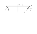
- a groove 13 extending in the rotational direction of the impeller 3 is formed on the inner wall surface of the bell mouth 5 instead of the protrusion 12.
- the groove 13 "extends in the rotation direction of the impeller 3" means that the groove 13 has a shape in which the dimension in the rotation direction of the impeller 3 is longer than the dimension in the rotation axis direction of the impeller 3. means.
- the groove 13 is an undulation forming portion that forms undulations on the inner wall surface of the bell mouth 5.
- the undulation of the inner wall surface of the bell mouth 5 is low in the portion of the groove 13 which is the undulation forming portion, and is high in the adjacent portion 5a of the inner wall surface of the bell mouth 5 adjacent to the undulation forming portion.
- FIG. 12 is a diagram showing a cross-sectional shape of a bell mouth and a groove in a second modification of the centrifugal blower according to the first embodiment.
- the suction port 4 of the bell mouth 5 as a reference, the distance between the suction port 4 of the bell mouth 5 and the large-diameter mouth surface 8 is defined as the bell mouth distance A, and the suction port 4 of the bell mouth 5 and the suction port 4 of the groove 13 are on the side.
- the distance from the end is defined as the groove distance E.
- the depth of the groove 13 is defined as F.
- the depth F of the groove 13 is the blade outer diameter D in consideration of the effect of the groove 13 while avoiding a sudden change in the plate thickness of the bell mouth 5 when considering the molding of the bell mouth 5 by the resin. It is said to be 1.1% of. That is, the centrifugal blower 1 according to the second modification of the first embodiment has the same as the centrifugal blower 1 according to the first embodiment, except that the convex direction due to the protrusion 12 and the concave direction due to the groove 13 are opposite to each other. The same is true.
- the groove 13 is formed on the inner wall surface of the bell mouth 5 to form a vortex due to the undulations of the inner wall surface. Resistance is generated and continuity cannot be maintained, and the loss due to the secondary flow generated inside the centrifugal blower 1 is improved.
- FIG. 13 is a diagram showing a third modification of the centrifugal blower according to the first embodiment.
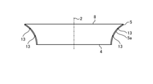
- the third modification two grooves 13 are formed on the inner wall surface of the bell mouth 5 at intervals in the axial direction of the motor shaft 11. Even when a plurality of grooves 13 are formed, the continuity of the vortices generated near the inner wall surface of the bell mouth 5 is not maintained, and the loss due to the secondary flow generated inside the centrifugal blower 1 is improved.
- an example in which two grooves 13 are formed is shown, but the number of grooves 13 may be three or more.
- FIG. 14 is a diagram showing a fourth modification of the centrifugal blower according to the first embodiment.
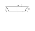
- the inner wall surface of the bell mouth 5 is provided with protrusions 12 and grooves 13 extending in the rotational direction of the impeller 3, and the protrusions 12 and grooves 13 cause undulations on the inner wall surface of the bell mouth 5. It is formed. That is, the protrusion 12 and the groove 13 extending in the rotation direction of the impeller 3 are undulation forming portions that form undulations on the inner wall surface of the bell mouth 5.
- the undulation of the inner wall surface of the bell mouth 5 is high in the portion of the protrusion 12 which is the undulation forming portion around the protrusion 12, and is low in the adjacent portion 5a of the inner wall surface of the bell mouth 5 adjacent to the undulation forming portion. It has become.
- the undulation of the inner wall surface of the bell mouth 5 is low in the portion of the groove 13 which is the undulation forming portion around the groove 13, and the adjacent portion 5a of the inner wall surface of the bell mouth 5 adjacent to the undulation forming portion. It is getting higher.
- the protrusions 12 and the grooves 13 are formed one by one, but at least one of the protrusions 12 and the grooves 13 may be formed in plurality.
- FIG. 15 is a diagram showing the effect of improving the fan efficiency of the centrifugal blower according to the first embodiment.
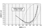
- FIG. 16 is a diagram showing the effect of improving the specific noise of the centrifugal blower according to the first embodiment.
- FIG. 17 is a diagram showing the effect of improving the static pressure of the centrifugal blower according to the first embodiment.
- the horizontal axis indicates the air volume.
- the vertical axis shows the fan efficiency.
- the vertical axis indicates the specific noise.
- the vertical axis shows the static pressure of the fan.
- the plots marked with triangles represent the centrifugal blower 1 according to the first embodiment, and the plots marked with circles represent the centrifugal blower according to the comparative example.
- the centrifugal blower 1 according to the first embodiment has an improved fan efficiency of 0.7 points to 1.6 points at the same air volume as compared with the centrifugal blower according to the comparative example. Further, the centrifugal blower 1 according to the first embodiment has a specific noise smaller than 0.3 dB to 0.8 dB as compared with the centrifugal blower according to the comparative example. Further, the centrifugal blower 1 according to the first embodiment has an improved static pressure of 3% to 12% as compared with the centrifugal blower according to the comparative example.
- the centrifugal blower 1 according to the first embodiment and the centrifugal blower 1 according to each modification are improved in fan efficiency and static pressure by forming at least one of a protrusion 12 and a groove 13 on the inner wall surface of the bell mouth 5. Noise reduction is realized. That is, the centrifugal blower 1 according to the first embodiment can achieve both low noise and high efficiency.
- Embodiment 2 The centrifugal blower 1 according to the second embodiment is different from the centrifugal blower 1 according to the first embodiment in that a protrusion 12 extending in the rotation direction of the impeller 3 is provided partially instead of the entire circumference.
- the same reference numerals are given to the portions common to the centrifugal blower 1 according to the first embodiment, and duplicate description will be omitted.
- FIG. 18 is a diagram showing the noise reduction effect and the fan efficiency improvement effect of the centrifugal blower according to the second embodiment. All the measured values in FIG. 18 are numerical values at the open point.
- the specific noise and the fan efficiency in FIG. 18 are the differences from the centrifugal blower according to the comparative example not provided with the protrusion 12, respectively.
- the noise reduction effect was the highest when the protrusion 12 was provided in the range of ⁇ 70 ° ⁇ ⁇ ⁇ 20 °.
- the improvement value of the specific noise by providing the protrusion 12 in the range of ⁇ 70 ° ⁇ ⁇ ⁇ 20 ° is 0.57 dB.
- the range of ⁇ 70 ° ⁇ ⁇ ⁇ 20 ° is close to the tongue portion 7 and the outlet 6a, and the non-stationarity of the secondary flow tends to be strong, so that the noise reduction effect of the protrusion 12 is remarkable.
- the improvement value of the specific noise by providing the protrusion 12 in the range of 200 ° ⁇ ⁇ ⁇ 290 ° is 0.53 dB.
- the improvement value of the specific noise by providing the protrusion 12 in the range of 20 ° ⁇ ⁇ ⁇ 110 ° is 0.51 dB.
- the improvement value of the specific noise by providing the protrusion 12 in the range of 110 ° ⁇ ⁇ ⁇ 200 ° is 0.17 dB. Since the range of 110 ° ⁇ ⁇ ⁇ 200 ° is far from the tongue portion 7 and the outlet 6a, the non-stationarity of the vortex is weak and the noise reduction effect of the protrusion 12 is small.
- the protrusion 12 may be provided in two or more ranges.
- the protrusion 12 may be provided in both the range of ⁇ 70 ° ⁇ ⁇ ⁇ 20 ° and the range of 200 ° ⁇ ⁇ ⁇ 290 °.
- the centrifugal blower 1 has a protrusion 12 extending in the rotation direction of the impeller 3 and a groove extending in the rotation direction of the impeller 3 in a part of the inner wall surface of the bell mouth 5 around the rotation axis 2. Since at least one of 13 is formed, it is possible to realize low noise and high efficiency.
- FIG. 19 is a cross-sectional view of the centrifugal blower according to the third embodiment.
- FIG. 19 schematically shows a cross section of the centrifugal blower 1 according to the third embodiment.
- the centrifugal blower 1 according to the first embodiment is a single suction type equipped with one bell mouth 5, whereas the centrifugal blower 1 according to the third embodiment is a double suction type provided with two bell mouths 5. It differs from the centrifugal blower 1 according to the first embodiment in a certain point.
- the same reference numerals are given to the portions common to the centrifugal blower 1 according to the first embodiment, and duplicate description will be omitted.
- the centrifugal blower 1 according to the third embodiment which is a double suction type, is provided with protrusions 12 extending in the rotational direction of the impeller 3 on the inner wall surface of each of the two bell mouths 5, and the two bell mouths are provided by the protrusions 12. Ups and downs are formed on the inner wall surface of each of 5.
- the protrusion 12 is an undulation forming portion that forms an undulation on the inner wall surface of the bell mouth 5.
- the undulation of the inner wall surface of the bell mouth 5 is high at the portion of the protrusion 12 which is the undulation forming portion, and is low at the adjacent portion 5a of the inner wall surface of the bell mouth 5 adjacent to the undulation forming portion. Since the centrifugal blower 1 according to the third embodiment is provided with protrusions 12 on the inner wall surface of each of the two bell mouths 5, it is possible to achieve both low noise and high efficiency.
- a groove 13 may be provided in at least one of the bell mouths 5. That is, by forming at least one of the protrusion 12 and the groove 13 on the inner wall surface of each of the two bell mouths 5, it is possible to realize low noise and high efficiency.
- the configuration shown in the above embodiment is an example of the content, can be combined with another known technique, and a part of the configuration is omitted or changed without departing from the gist. It is also possible.
Landscapes
- Engineering & Computer Science (AREA)
- Mechanical Engineering (AREA)
- General Engineering & Computer Science (AREA)
- Structures Of Non-Positive Displacement Pumps (AREA)
Abstract
遠心送風機(1)は、駆動モータ(10)と、駆動モータ(10)のモータシャフト(11)に固定され、モータシャフト(11)の回転軸(2)を中心に回転する羽根車(3)と、羽根車(3)へ向かって空気が流入する吸込口(4)、及び吸込口(4)よりも羽根車(3)に流入する空気の流れの上流側に配置された大径口面(8)を有するベルマウス(5)と、羽根車(3)が発生させた気流を吹き出す吹出口を有し、羽根車(3)を収容するケーシング本体(6)とを備えたスクロールケーシング(20)とを備え、スクロールケーシング(20)の内側を向いたベルマウス(5)の内壁面には、羽根車(3)の回転方向に伸びる突起(12)が設けられており、突起(12)によってベルマウス(5)の内壁面に起伏が形成されている。
Description
本開示は、ベルマウスが設けられたスクロールケーシングを備えた遠心送風機に関する。
遠心送風機は、羽根車を収容するスクロールケーシングの開口を有する面に、ベルマウスを備えている。羽根車の回転又は駆動モータの運転によって遠心送風機のスクロールケーシング内で発生した騒音は、ベルマウスを通じてスクロールケーシングの外へ放射される。
特許文献1には、ベルマウスの外周面に羽根車の回転方向に間隔をあけて、羽根車の回転軸の方向に伸びる複数の突起を設けることで、再吸い込み流れを抑制してファン効率を向上させた遠心送風機が開示されている。
遠心送風機には、ファン効率のみならず静粛性の向上も要求される。特許文献1に開示される遠心送風機は、ファン効率の向上には寄与するが、低騒音化の手立てが何ら講じられていない。
本開示は、上記に鑑みてなされたものであって、低騒音化と高効率化との両立を図った遠心送風機を得ることを目的とする。
上述した課題を解決し、目的を達成するために、本開示に係る遠心送風機は、駆動モータと、駆動モータのモータシャフトに固定され、モータシャフトの回転軸を中心に回転する羽根車と、羽根車へ向かって空気が流入する吸込口、及び吸込口よりも羽根車に流入する空気の流れの上流側に配置された大径口面を有するベルマウスと、羽根車が発生させた気流を吹き出す吹出口を有し、羽根車を収容するケーシング本体とを備えたスクロールケーシングとを備える。スクロールケーシングの内側を向いたベルマウスの内壁面には、羽根車の回転方向に伸びる起伏形成部が設けられている。起伏形成部によってベルマウスの内壁面に起伏が形成されている。
本開示に係る遠心送風機は、低騒音化と高効率化との両立を図れるという効果を奏する。
以下に、実施の形態に係る遠心送風機を図面に基づいて詳細に説明する。
実施の形態1.
図1は、実施の形態1に係る遠心送風機の斜視図である。図2は、実施の形態1に係る遠心送風機の断面図である。図2は、図1中のII-II線に沿った断面を模式的に示している。実施の形態1に係る遠心送風機1は、駆動モータ10と、駆動モータ10のモータシャフト11に固定された羽根車3とを備える。また、遠心送風機1は、羽根車3に空気を取り込むベルマウス5と、羽根車3が発生させた気流Y2を吹き出す吹出口6a、及び羽根車3が発生させた気流Y1を吹出口6aに導く舌部7とを備え、羽根車3を収容するケーシング本体6とを有するスクロールケーシング20を備える。ベルマウス5は、羽根車3に上流側から流入する主流Y3が流入する吸込口4と、吸込口4よりも主流Y3の上流側に配置された大径口面8とを有する。
図1は、実施の形態1に係る遠心送風機の斜視図である。図2は、実施の形態1に係る遠心送風機の断面図である。図2は、図1中のII-II線に沿った断面を模式的に示している。実施の形態1に係る遠心送風機1は、駆動モータ10と、駆動モータ10のモータシャフト11に固定された羽根車3とを備える。また、遠心送風機1は、羽根車3に空気を取り込むベルマウス5と、羽根車3が発生させた気流Y2を吹き出す吹出口6a、及び羽根車3が発生させた気流Y1を吹出口6aに導く舌部7とを備え、羽根車3を収容するケーシング本体6とを有するスクロールケーシング20を備える。ベルマウス5は、羽根車3に上流側から流入する主流Y3が流入する吸込口4と、吸込口4よりも主流Y3の上流側に配置された大径口面8とを有する。
羽根車3は、モータシャフト11に固定されたボス部9と、ボス部9の周縁部に設置された羽根3aとを備えている。
ベルマウス5のうち、スクロールケーシング20の内側を向いた壁面には、羽根車3の回転方向に伸びる突起12が全周にわたって設けられている。突起12は、モータシャフト11の回転軸2を中心軸とする回転対称形状である。以下、ベルマウス5のうち、スクロールケーシング20の内側を向いた壁面を「内壁面」という。ベルマウス5の内壁面には、羽根車3の回転方向に伸びる突起12が設けられており、突起12によってベルマウス5の内壁面に起伏が形成されている。なお、突起12が「羽根車3の回転方向に伸びる」とは、突起12が、羽根車3の回転方向の寸法の方が羽根車3の回転軸方向の寸法よりも長い形状であることを意味する。突起12は、ベルマウス5の内壁面に起伏を形成する起伏形成部である。ベルマウス5の内壁面の起伏は、起伏形成部である突起12の部分で高くなっており、ベルマウス5の内壁面のうち起伏形成部に隣接する隣接部5aで低くなっている。
図3は、実施の形態1に係る遠心送風機のベルマウス及び突起の断面形状を示す図である。ベルマウス5の吸込口4を基準とし、ベルマウス5の吸込口4と大径口面8との距離をベルマウス距離Aとし、ベルマウス5の吸込口4と突起12の吸込口4側の端との距離を突起距離Bと定める。また、突起12の突き出し長さをCとする。また、羽根車3の羽根外径をDとする。
突起12はベルマウス5と一体になるため、樹脂を金型で成型することも踏まえた形状になっている。例えば、突起12の突き出し長さCは、羽根車3の羽根外径Dの1.1%とされている。すなわち、C=D×0.011である。突き出し長さCは、ベルマウス5の樹脂による成型を考慮した時に、ベルマウス5の板厚が急激に変化することを避けつつ、突起12がもたらす後述の効果との兼ね合いから、羽根外径Dの1.1%とされている。一般的に送風機は、羽根外径Dによる性能への依存度が高いため、突起12の突き出し長さCは、羽根外径Dで無次元化して大きさを定めている。
さらに、気流の乱れを生じさせないように、突起12の先端は尖った形状ではなく、丸みを帯びた形状にされている。
実施の形態1に係る遠心送風機1においては、突起距離Bは、ベルマウス距離Aの0.75倍とされている。すなわち、B=A×0.75である。
図2に示すように、羽根車3が回転することによって形成された主流Y3は、ベルマウス5を通過し、スクロールケーシング20の内部に吸い込まれる。スクロールケーシング20に吸い込まれた主流Y3は、吹出口6aに向かう。ベルマウス5の内壁面周辺では、羽根車3が回転することによって、主流Y3とは異なる向きに流れる二次流れY5,Y6が形成される。二次流れY5,Y6の発生に伴い、ベルマウス5の内壁面周辺で渦が発生したり、発生した渦同士が干渉したりすると、遠心送風機1の内部で損失が生じ、騒音の増大とファン効率の低下とを招く。
図4は、実施の形態1に係る遠心送風機の騒音低減効果を示す図である。図4の横軸は、突起距離Bをベルマウス距離Aで除した値である。例えば、B/A=0.85は、ベルマウス距離Aの85%の位置に突起12を設けることと同義である。図4の縦軸は、突起12を備えない比較例に係る遠心送風機と比較した場合の騒音低減効果を示す。
図4から、ベルマウス距離Aの75%の位置に突起12を設けた場合には、0.61dBの騒音低減効果が得られることが分かる。また、ベルマウス距離Aの25%の位置に突起12を設けることにより0.18dBの騒音低減効果が得られ、ベルマウス距離Aの50%の位置に突起12を設けることにより0.55dBの騒音低減効果が得られ、ベルマウス距離Aの85%の位置に突起12を設けることにより0.27dBの騒音低減効果が得られることが分かる。後述するように、ベルマウス5の内壁面の表面又は内壁面周辺では、吸込口4からの回転軸2の軸方向の距離によらず絶えず渦が生じており、渦の発生及び渦同士の干渉によって非定常性が強くなりやすいため、突起距離Bが異なっても低減効果が得られる。
突起12をベルマウス5の内壁面に沿うように設けることで、主流Y3とは異なる向きに流れる二次流れY5の経路を寸断することができ、突起12を設けない場合と比較して、突起12よりも下流側には二次流れY6が生じにくくなる。すなわち、突起12を設けない場合と比較して、気流の乱れの原因となる渦が生じにくくなり、気流の乱れによる二次損失も発生しにくくなる。さらに、突起12を設けることにより、渦同士の干渉が抑制されるため、低騒音化と高効率化とを両立させることができる。
図5は、実施の形態1に係る遠心送風機の平面図である。回転軸2と舌部7の先端とを結ぶ線を基準とし、羽根車3の回転方向が正となるように角度θを定義する。すなわち、モータシャフト11の回転軸2と舌部7の先端とを結ぶ仮想線を、羽根車3の回転方向への角度θ=0°の基準位置とする。また、図5には、角度θ=0°、20°、65°、110°、150°、200°、245°、290°及び330°の各位置を図示している。なお、θ=290°は、θ=-70°と同義である。
図6及び図7は、実施の形態1に係る遠心送風機の内部流れの流体解析結果を示す図である。図8及び図9は、実施の形態1の比較例に係る遠心送風機の内部流れの流体解析結果を示す図である。流体解析結果は、渦の強さを示す速度勾配テンソルの第2不変量を用いて示している。なお、速度勾配テンソルの第2不変量の単位は[/s2]である。渦の分布は視認性を考慮し、色が黒に近いほど渦が強いことを示し、色が白に近いほど渦が弱いことを示すようにした。なお、黒色は、100000/s2であり、白色は、0/s2である。
θ=65°側のベルマウス5付近で発生している渦に注目すると、突起12を備える実施の形態1に係る遠心送風機1では、壁面の近くで強い渦X1を生じ、ベルマウス5から離れた箇所でも強い渦X2が生じている。一方、突起12を備えない比較例に係る遠心送風機では、ベルマウス51付近に強い渦X3が生じており、ベルマウス51から離れた箇所でも強い渦X4が発生している。渦X1と渦X2との距離と、渦X3と渦X4との距離とを比較すると、渦X3と渦X4との距離の方が短いため、突起12を備えない比較例に係る遠心送風機の方が渦の干渉が発生しやすいことが分かる。
渦同士が干渉すると、遠心送風機1内部における気流の非定常性が増し、ベルマウス5の内壁面の表面で気流が乱れる箇所の増加につながり、騒音源の増加を招く。したがって、渦同士の干渉は避けるのが望ましい。舌部7の通過後であるθ=65°側の領域は、気流の乱れが増大しやすい領域でもあり、ベルマウス5付近で生じる渦の抑制効果も大きくなりやすい。
また、θ=245°側で発生している渦に注目すると、突起12を備える実施の形態1に係る遠心送風機1では、ベルマウス5の壁面に沿うように強い渦X5が形成されているが、突起12によって発生範囲は抑制されている。一方、突起12を備えない比較例に係る遠心送風機では、ベルマウス51の壁面に沿う強い渦X6は、広範囲にわたって壁面に沿って形成されている。θ=65°側のような渦同士の干渉は生じていないものの、θ=245°側の領域は吹出口6aに近く、主流Y3が速度を上げながら吹出口6aに向かう領域であるため、渦の寸断効果が大きくなりやすい。
また、θ=150°側で発生している渦に注目すると、突起12を備える実施の形態1に係る遠心送風機1では、ベルマウス5付近で発生している渦は、強い渦X7と強い渦X8とに突起12によって分断されている。一方、突起12を備えない比較例に係る遠心送風機では、ベルマウス51付近で発生している渦X9は分断されていない。θ=150°付近の領域は、舌部7及び吹出口6aから遠いため、非定常性が弱く、渦に乱れ及び変動が生じにくい。このため、θ=150°付近の領域では、他の領域と比較すると、渦の挙動の変化は顕著ではない。すなわち、θ=150°付近の領域は、ベルマウス5の内壁面で渦が顕著に発生する領域ではなく、突起12による渦の分断の効果も生じにくい。
また、θ=330°側で発生している渦に注目すると、突起12を備える実施の形態1に係る遠心送風機1の渦X10の発生範囲は、突起12を備えない比較例に係る遠心送風機の渦X11、渦X12及び渦X13の発生範囲よりも広く見えるが、比較例に係る遠心送風機では、渦X11、渦X12及び渦X13の三つが発生しており、渦同士の距離が近いため、複数の渦が干渉している。θ=330°付近の領域は、舌部7及び吹出口6aに近い領域であり、遠心送風機1の非定常性が強くなる領域である。したがって、θ=330°付近の領域では、ベルマウス5の周辺で生じる気流の乱れが増大しやすく、ベルマウス5付近で生じる渦の抑制効果も大きくなりやすい。突起12を備えない比較例に係る遠心送風機は、ベルマウス51の内壁面の表面に複数の強い渦X11、渦X12及び渦X13が発生して、お互いに干渉し合うことにより非定常性を有する渦が増えることになり、騒音源の増加とエネルギー損失増大を招くことが容易に予想できる。
このように、流体解析結果から、羽根車3の回転方向に伸びる突起12をベルマウス5の内壁面に設けることで、ベルマウス5の内壁面で生じる渦を抑制するだけでなく、渦同士の干渉を抑制できることも確認できる。
突起12を設ける位置について、流体解析では1条件のみ示したが、ベルマウス5の内壁面付近では、ベルマウス5の内壁面の表面の概ね全域で渦が発生しているため、0≦B<Aを満たす条件で突起12を設ければ、ベルマウス5の壁面での渦の発生及び渦同士の干渉を抑制でき、低騒音化と高効率化との両立を達成できる。
図10は、実施の形態1に係る遠心送風機の第1の変形例を示す図である。第1の変形例においては、ベルマウス5の内壁面に突起12を、モータシャフト11の軸方向に間隔を空けて三つ形成している。第1の変形例に示すように、突起12はベルマウス5の内壁面に複数設けられてもよい。ここでは、突起12を三つ設けた例を示したが、突起12の数は二つでも良いし、四つ以上でも良い。
図11は、実施の形態1に係る遠心送風機の第2の変形例を示す図である。第2の変形例においては、ベルマウス5の内壁面に突起12の代わりに羽根車3の回転方向に伸びる溝13を形成している。なお、溝13が「羽根車3の回転方向に伸びる」とは、溝13が、羽根車3の回転方向の寸法の方が羽根車3の回転軸方向の寸法よりも長い形状であることを意味する。溝13は、ベルマウス5の内壁面に起伏を形成する起伏形成部である。ベルマウス5の内壁面の起伏は、起伏形成部である溝13の部分で低くなっており、ベルマウス5の内壁面のうち起伏形成部に隣接する隣接部5aで高くなっている。
図12は、実施の形態1に係る遠心送風機の第2の変形例におけるベルマウス及び溝の断面形状を示す図である。ベルマウス5の吸込口4を基準とし、ベルマウス5の吸込口4と大径口面8との距離をベルマウス距離Aとし、ベルマウス5の吸込口4と溝13の吸込口4側の端との距離を溝距離Eと定める。また、溝13の深さをFと定義する。溝13の深さFは、ベルマウス5の樹脂による成型を考慮した時に、ベルマウス5の板厚が急激に変化することを避けつつ、溝13がもたらす効果との兼ね合いから、羽根外径Dの1.1%とされている。すなわち、実施の形態1の第2の変形例に係る遠心送風機1は、突起12による凸と、溝13による凹の方向が逆方向であることを除き、実施の形態1に係る遠心送風機1と同様である。
ベルマウス5の内壁面付近で生じる渦は、内壁面に連続的に沿うような形態を呈しているため、ベルマウス5の内壁面に溝13を形成することにより、内壁面の起伏によって渦に抵抗が生じて連続性が保てなくなり、遠心送風機1内部で発生する二次流れによる損失が改善される。
図13は、実施の形態1に係る遠心送風機の第3の変形例を示す図である。第3の変形例においては、ベルマウス5の内壁面に、溝13を、モータシャフト11の軸方向に間隔を空けて二つ形成している。溝13を複数形成した場合も、ベルマウス5の内壁面付近で生じる渦の連続性が保たれなくなり、遠心送風機1内部で発生する二次流れによる損失が改善される。ここでは溝13を二つ形成した例を示したが、溝13の数は、三つ以上でも良い。
図14は、実施の形態1に係る遠心送風機の第4の変形例を示す図である。第4の変形例においては、ベルマウス5の内壁面に、羽根車3の回転方向に伸びる突起12及び溝13が設けられており、突起12及び溝13によってベルマウス5の内壁面に起伏が形成されている。すなわち、羽根車3の回転方向に伸びる突起12及び溝13が、ベルマウス5の内壁面に起伏を形成する起伏形成部である。ベルマウス5の内壁面の起伏は、突起12の周辺では、起伏形成部である突起12の部分で高くなっており、ベルマウス5の内壁面のうち起伏形成部に隣接する隣接部5aで低くなっている。一方、ベルマウス5の内壁面の起伏は、溝13の周辺では、起伏形成部である溝13の部分で低くなっており、ベルマウス5の内壁面のうち起伏形成部に隣接する隣接部5aで高くなっている。突起12及び溝13の両方を形成した場合も、ベルマウス5の内壁面付近で生じる渦の連続性が保たれなくなり、遠心送風機1内部で発生する二次流れによる損失が改善される。ここでは突起12及び溝13を一つずつ形成した例を示したが、突起12及び溝13の少なくとも一方を複数形成しても良い。
図15は、実施の形態1に係る遠心送風機のファン効率の改善効果を示す図である。図16は、実施の形態1に係る遠心送風機の比騒音の改善効果を示す図である。図17は、実施の形態1に係る遠心送風機の静圧の改善効果を示す図である。図15、図16及び図17において、横軸は風量を示している。図15において、縦軸はファン効率を示している。図16において、縦軸は比騒音を示している。図17において、縦軸はファン静圧を示している。図15、図16及び図17において、三角印のプロットは実施の形態1に係る遠心送風機1を表し、丸印のプロットは比較例に係る遠心送風機を表す。
実施の形態1に係る遠心送風機1は、比較例に係る遠心送風機と比較して、同一風量におけるファン効率が、0.7ポイントから1.6ポイント向上している。また、実施の形態1に係る遠心送風機1は、比較例に係る遠心送風機と比較して、比騒音が0.3dBから0.8dB小さくなっている。また、実施の形態1に係る遠心送風機1は、比較例に係る遠心送風機と比較して、静圧が3%から12%向上している。
実施の形態1に係る遠心送風機1及び各変形例に係る遠心送風機1は、ベルマウス5の内壁面に突起12及び溝13の少なくとも一方を形成することによって、ファン効率及び静圧の向上と比騒音の低減とが実現される。すなわち、実施の形態1に係る遠心送風機1は、低騒音化と高効率化とを両立させることができる。
実施の形態2.
実施の形態2に係る遠心送風機1は、羽根車3の回転方向に伸びる突起12が全周ではなく部分的に設けられている点で、実施の形態1に係る遠心送風機1と相違する。実施の形態1に係る遠心送風機1と共通する部分には同じ符号を付し、重複する説明は省略する。図18は、実施の形態2に係る遠心送風機の騒音低減効果及びファン効率向上効果を示す図である。図18における実測値は全て、開放点における数値である。図18における比騒音及びファン効率は、それぞれ、突起12を備えない比較例に係る遠心送風機との差である。
実施の形態2に係る遠心送風機1は、羽根車3の回転方向に伸びる突起12が全周ではなく部分的に設けられている点で、実施の形態1に係る遠心送風機1と相違する。実施の形態1に係る遠心送風機1と共通する部分には同じ符号を付し、重複する説明は省略する。図18は、実施の形態2に係る遠心送風機の騒音低減効果及びファン効率向上効果を示す図である。図18における実測値は全て、開放点における数値である。図18における比騒音及びファン効率は、それぞれ、突起12を備えない比較例に係る遠心送風機との差である。
図18に示すように、-70°≦θ≦20°の範囲に突起12を設けた場合の騒音低減効果が最も高かった。-70°≦θ≦20°の範囲に突起12を設けることによる比騒音の改善値は、0.57dBである。-70°≦θ≦20°の範囲は、舌部7及び吹出口6aに近く、二次流れの非定常性が強くなりやすいため、突起12による騒音低減効果が顕著に表れている。
図18に示すように、200°≦θ≦290°の範囲に突起12を設けることによる比騒音の改善値は、0.53dBである。また、20°≦θ≦110°の範囲に突起12を設けることによる比騒音の改善値は、0.51dBである。110°≦θ≦200°の範囲に突起12を設けることによる比騒音の改善値は、0.17dBである。110°≦θ≦200°の範囲は、舌部7及び吹出口6aから遠いため、渦の非定常性が弱く、突起12による騒音低減効果が小さくなっている。
なお、ここでは複数の範囲のうちの一つに突起12を設けることによる騒音低減効果を検討したが、二つ以上の範囲に突起12を設けてもよい。例えば、-70°≦θ≦20°の範囲、及び200°≦θ≦290°の範囲の両方に突起12を設けてもよい。
また、四つの範囲のうちの何れに突起12を設けた場合も、ファン効率が低下することはなかった。
実施の形態2に係る遠心送風機1は、ベルマウス5の内壁面のうち回転軸2周りにおける一部の領域に、羽根車3の回転方向に伸びる突起12及び羽根車3の回転方向に伸びる溝13の少なくとも一方が形成されているため、低騒音化と高効率化とを実現できる。
実施の形態3.
図19は、実施の形態3に係る遠心送風機の断面図である。図19は、実施の形態3に係る遠心送風機1の断面を模式的に示している。実施の形態1に係る遠心送風機1は、ベルマウス5を一つ備えた片吸込型であったが、実施の形態3に係る遠心送風機1は、ベルマウス5を二つ備えた両吸込型である点で実施の形態1に係る遠心送風機1と相違する。実施の形態1に係る遠心送風機1と共通する部分には同じ符号を付し、重複する説明は省略する。
図19は、実施の形態3に係る遠心送風機の断面図である。図19は、実施の形態3に係る遠心送風機1の断面を模式的に示している。実施の形態1に係る遠心送風機1は、ベルマウス5を一つ備えた片吸込型であったが、実施の形態3に係る遠心送風機1は、ベルマウス5を二つ備えた両吸込型である点で実施の形態1に係る遠心送風機1と相違する。実施の形態1に係る遠心送風機1と共通する部分には同じ符号を付し、重複する説明は省略する。
両吸込型である実施の形態3に係る遠心送風機1は、二つのベルマウス5の各々の内壁面に羽根車3の回転方向に伸びる突起12が設けられており、突起12によって二つのベルマウス5の各々の内壁面に起伏が形成されている。突起12は、ベルマウス5の内壁面に起伏を形成する起伏形成部である。ベルマウス5の内壁面の起伏は、起伏形成部である突起12の部分で高くなっており、ベルマウス5の内壁面のうち起伏形成部に隣接する隣接部5aで低くなっている。実施の形態3に係る遠心送風機1は、二つのベルマウス5の各々の内壁面に突起12が設けられているため、低騒音化と高効率化とを両立させることができる。
なお、ここでは二つのベルマウス5の各々の内壁面に突起12が設けられた構造を例に挙げたが、少なくとも一方のベルマウス5に溝13を設けてもよい。すなわち、二つのベルマウス5の各々の内壁面に、突起12及び溝13の少なくとも一方を形成することで、低騒音化と高効率化とを実現できる。
以上の実施の形態に示した構成は、内容の一例を示すものであり、別の公知の技術と組み合わせることも可能であるし、要旨を逸脱しない範囲で、構成の一部を省略、変更することも可能である。
1 遠心送風機、2 回転軸、3 羽根車、3a 羽根、4 吸込口、5,51 ベルマウス、5a 隣接部、6 ケーシング本体、6a 吹出口、7 舌部、8 大径口面、9 ボス部、10 駆動モータ、11 モータシャフト、12 突起、13 溝、20 スクロールケーシング。
Claims (7)
- 駆動モータと、
前記駆動モータのモータシャフトに固定され、前記モータシャフトの回転軸を中心に回転する羽根車と、
前記羽根車へ向かって空気が流入する吸込口、及び前記吸込口よりも前記羽根車に流入する空気の流れの上流側に配置された大径口面を有するベルマウスと、前記羽根車が発生させた気流を吹き出す吹出口を有し、前記羽根車を収容するケーシング本体とを備えたスクロールケーシングとを備え、
前記スクロールケーシングの内側を向いた前記ベルマウスの内壁面には、前記羽根車の回転方向に伸びる起伏形成部が設けられており、
前記起伏形成部によって前記ベルマウスの内壁面に起伏が形成されていることを特徴とする遠心送風機。 - 前記起伏形成部は、前記羽根車の回転方向に全周にわたって設けられていることを特徴とする請求項1に記載の遠心送風機。
- 前記スクロールケーシングは、前記羽根車が発生させた気流を前記吹出口へ導く舌部を備え、
前記モータシャフトの回転軸と前記舌部の先端とを結ぶ仮想線を、前記羽根車の回転方向への角度θ=0°の基準位置とし、
前記内壁面のうち、少なくとも-70°≦θ≦20°の範囲には、前記起伏形成部が設けられていることを特徴とする請求項1に記載の遠心送風機。 - 前記スクロールケーシングは、前記羽根車が発生させた気流を前記吹出口へ導く舌部を備え、
前記モータシャフトの回転軸と前記舌部の先端とを結ぶ仮想線を、前記羽根車の回転方向への角度θ=0°の基準位置とし、
前記内壁面のうち、少なくとも20°≦θ≦110°の範囲には、前記起伏形成部が設けられていることを特徴とする請求項1に記載の遠心送風機。 - 前記スクロールケーシングは、前記羽根車が発生させた気流を前記吹出口へ導く舌部を備え、
前記モータシャフトの回転軸と前記舌部の先端とを結ぶ仮想線を、前記羽根車の回転方向への角度θ=0°の基準位置とし、
前記内壁面のうち、少なくとも200°≦θ≦290°の範囲には、前記起伏形成部が設けられていることを特徴とする請求項1に記載の遠心送風機。 - 前記モータシャフトの軸方向に間隔を空けて、前記起伏形成部を複数設けたことを特徴とする請求項1から5のいずれか1項に記載の遠心送風機。
- 前記起伏形成部は、突起及び溝の少なくとも一方であることを特徴とする請求項1から6のいずれか1項に記載の遠心送風機。
Priority Applications (2)
| Application Number | Priority Date | Filing Date | Title |
|---|---|---|---|
| JP2022546788A JP7387013B2 (ja) | 2020-09-02 | 2020-09-02 | 遠心送風機 |
| PCT/JP2020/033334 WO2022049684A1 (ja) | 2020-09-02 | 2020-09-02 | 遠心送風機 |
Applications Claiming Priority (1)
| Application Number | Priority Date | Filing Date | Title |
|---|---|---|---|
| PCT/JP2020/033334 WO2022049684A1 (ja) | 2020-09-02 | 2020-09-02 | 遠心送風機 |
Publications (1)
| Publication Number | Publication Date |
|---|---|
| WO2022049684A1 true WO2022049684A1 (ja) | 2022-03-10 |
Family
ID=80491877
Family Applications (1)
| Application Number | Title | Priority Date | Filing Date |
|---|---|---|---|
| PCT/JP2020/033334 Ceased WO2022049684A1 (ja) | 2020-09-02 | 2020-09-02 | 遠心送風機 |
Country Status (2)
| Country | Link |
|---|---|
| JP (1) | JP7387013B2 (ja) |
| WO (1) | WO2022049684A1 (ja) |
Citations (2)
| Publication number | Priority date | Publication date | Assignee | Title |
|---|---|---|---|---|
| JPS6141899U (ja) * | 1985-07-17 | 1986-03-17 | 三菱電機株式会社 | 送風機 |
| JPH0337398A (ja) * | 1989-07-04 | 1991-02-18 | Matsushita Seiko Co Ltd | 多翼ファン |
-
2020
- 2020-09-02 WO PCT/JP2020/033334 patent/WO2022049684A1/ja not_active Ceased
- 2020-09-02 JP JP2022546788A patent/JP7387013B2/ja active Active
Patent Citations (2)
| Publication number | Priority date | Publication date | Assignee | Title |
|---|---|---|---|---|
| JPS6141899U (ja) * | 1985-07-17 | 1986-03-17 | 三菱電機株式会社 | 送風機 |
| JPH0337398A (ja) * | 1989-07-04 | 1991-02-18 | Matsushita Seiko Co Ltd | 多翼ファン |
Also Published As
| Publication number | Publication date |
|---|---|
| JPWO2022049684A1 (ja) | 2022-03-10 |
| JP7387013B2 (ja) | 2023-11-27 |
Similar Documents
| Publication | Publication Date | Title |
|---|---|---|
| KR102323777B1 (ko) | 송풍장치 및 이를 포함하는 공기조화기의 실외기 | |
| US7163371B2 (en) | Centrifugal fan | |
| AU2007209185B2 (en) | Improved impeller and fan | |
| US8870541B2 (en) | Centrifugal multiblade fan | |
| CN105793576B (zh) | 离心风扇 | |
| CN111656019B (zh) | 轴流送风机 | |
| CN107850083A (zh) | 送风机和搭载有该送风机的空调装置 | |
| US8038391B2 (en) | Vortex blower | |
| CN210152981U (zh) | 送风机 | |
| AU2007234497A1 (en) | Multiblade centrifugal blower | |
| CN115727008B (zh) | 进风圈和油烟机 | |
| JP2012140881A (ja) | 多翼送風機 | |
| US12140155B2 (en) | Blower | |
| JP6932295B1 (ja) | 送風機 | |
| JP7387027B2 (ja) | 遠心送風機 | |
| WO2022049684A1 (ja) | 遠心送風機 | |
| JP2006125229A (ja) | シロッコファン | |
| JP7413973B2 (ja) | 送風機 | |
| WO2020115872A1 (ja) | 遠心送風機 | |
| JP7466707B2 (ja) | 遠心送風機 | |
| JP2004353665A (ja) | 多翼遠心送風機 | |
| JPS6165097A (ja) | 軸流フアン | |
| WO2018173803A1 (ja) | 送風装置 | |
| WO2018138808A1 (ja) | 遠心送風機 |
Legal Events
| Date | Code | Title | Description |
|---|---|---|---|
| 121 | Ep: the epo has been informed by wipo that ep was designated in this application |
Ref document number: 20952423 Country of ref document: EP Kind code of ref document: A1 |
|
| ENP | Entry into the national phase |
Ref document number: 2022546788 Country of ref document: JP Kind code of ref document: A |
|
| NENP | Non-entry into the national phase |
Ref country code: DE |
|
| 122 | Ep: pct application non-entry in european phase |
Ref document number: 20952423 Country of ref document: EP Kind code of ref document: A1 |