WO2022044929A1 - 歯科造形物の画像データ作成方法、歯科造形物の画像データ作成装置、歯科造形物の画像データ作成プログラム、歯科造形物の製造方法及び歯科造形物 - Google Patents
歯科造形物の画像データ作成方法、歯科造形物の画像データ作成装置、歯科造形物の画像データ作成プログラム、歯科造形物の製造方法及び歯科造形物 Download PDFInfo
- Publication number
- WO2022044929A1 WO2022044929A1 PCT/JP2021/030231 JP2021030231W WO2022044929A1 WO 2022044929 A1 WO2022044929 A1 WO 2022044929A1 JP 2021030231 W JP2021030231 W JP 2021030231W WO 2022044929 A1 WO2022044929 A1 WO 2022044929A1
- Authority
- WO
- WIPO (PCT)
- Prior art keywords
- image data
- dental model
- reinforcing member
- side wall
- denture base
- Prior art date
- Legal status (The legal status is an assumption and is not a legal conclusion. Google has not performed a legal analysis and makes no representation as to the accuracy of the status listed.)
- Ceased
Links
Images


Classifications
-
- A—HUMAN NECESSITIES
- A61—MEDICAL OR VETERINARY SCIENCE; HYGIENE
- A61C—DENTISTRY; APPARATUS OR METHODS FOR ORAL OR DENTAL HYGIENE
- A61C13/00—Dental prostheses; Making same
- A61C13/0003—Making bridge-work, inlays, implants or the like
- A61C13/0004—Computer-assisted sizing or machining of dental prostheses
-
- A—HUMAN NECESSITIES
- A61—MEDICAL OR VETERINARY SCIENCE; HYGIENE
- A61C—DENTISTRY; APPARATUS OR METHODS FOR ORAL OR DENTAL HYGIENE
- A61C13/00—Dental prostheses; Making same
- A61C13/0003—Making bridge-work, inlays, implants or the like
- A61C13/0006—Production methods
- A61C13/0013—Production methods using stereolithographic techniques
-
- A—HUMAN NECESSITIES
- A61—MEDICAL OR VETERINARY SCIENCE; HYGIENE
- A61C—DENTISTRY; APPARATUS OR METHODS FOR ORAL OR DENTAL HYGIENE
- A61C13/00—Dental prostheses; Making same
- A61C13/0003—Making bridge-work, inlays, implants or the like
- A61C13/0006—Production methods
- A61C13/0019—Production methods using three dimensional printing
-
- A—HUMAN NECESSITIES
- A61—MEDICAL OR VETERINARY SCIENCE; HYGIENE
- A61C—DENTISTRY; APPARATUS OR METHODS FOR ORAL OR DENTAL HYGIENE
- A61C13/00—Dental prostheses; Making same
- A61C13/01—Palates or other bases or supports for the artificial teeth; Making same
-
- A—HUMAN NECESSITIES
- A61—MEDICAL OR VETERINARY SCIENCE; HYGIENE
- A61C—DENTISTRY; APPARATUS OR METHODS FOR ORAL OR DENTAL HYGIENE
- A61C9/00—Impression cups, i.e. impression trays; Impression methods
- A61C9/004—Means or methods for taking digitized impressions
- A61C9/0046—Data acquisition means or methods
-
- B—PERFORMING OPERATIONS; TRANSPORTING
- B33—ADDITIVE MANUFACTURING TECHNOLOGY
- B33Y—ADDITIVE MANUFACTURING, i.e. MANUFACTURING OF THREE-DIMENSIONAL [3D] OBJECTS BY ADDITIVE DEPOSITION, ADDITIVE AGGLOMERATION OR ADDITIVE LAYERING, e.g. BY 3D PRINTING, STEREOLITHOGRAPHY OR SELECTIVE LASER SINTERING
- B33Y50/00—Data acquisition or data processing for additive manufacturing
-
- B—PERFORMING OPERATIONS; TRANSPORTING
- B33—ADDITIVE MANUFACTURING TECHNOLOGY
- B33Y—ADDITIVE MANUFACTURING, i.e. MANUFACTURING OF THREE-DIMENSIONAL [3D] OBJECTS BY ADDITIVE DEPOSITION, ADDITIVE AGGLOMERATION OR ADDITIVE LAYERING, e.g. BY 3D PRINTING, STEREOLITHOGRAPHY OR SELECTIVE LASER SINTERING
- B33Y80/00—Products made by additive manufacturing
-
- B—PERFORMING OPERATIONS; TRANSPORTING
- B29—WORKING OF PLASTICS; WORKING OF SUBSTANCES IN A PLASTIC STATE IN GENERAL
- B29C—SHAPING OR JOINING OF PLASTICS; SHAPING OF MATERIAL IN A PLASTIC STATE, NOT OTHERWISE PROVIDED FOR; AFTER-TREATMENT OF THE SHAPED PRODUCTS, e.g. REPAIRING
- B29C64/00—Additive manufacturing, i.e. manufacturing of three-dimensional [3D] objects by additive deposition, additive agglomeration or additive layering, e.g. by 3D printing, stereolithography or selective laser sintering
- B29C64/10—Processes of additive manufacturing
- B29C64/106—Processes of additive manufacturing using only liquids or viscous materials, e.g. depositing a continuous bead of viscous material
- B29C64/124—Processes of additive manufacturing using only liquids or viscous materials, e.g. depositing a continuous bead of viscous material using layers of liquid which are selectively solidified
-
- B—PERFORMING OPERATIONS; TRANSPORTING
- B29—WORKING OF PLASTICS; WORKING OF SUBSTANCES IN A PLASTIC STATE IN GENERAL
- B29C—SHAPING OR JOINING OF PLASTICS; SHAPING OF MATERIAL IN A PLASTIC STATE, NOT OTHERWISE PROVIDED FOR; AFTER-TREATMENT OF THE SHAPED PRODUCTS, e.g. REPAIRING
- B29C64/00—Additive manufacturing, i.e. manufacturing of three-dimensional [3D] objects by additive deposition, additive agglomeration or additive layering, e.g. by 3D printing, stereolithography or selective laser sintering
- B29C64/30—Auxiliary operations or equipment
- B29C64/386—Data acquisition or data processing for additive manufacturing
-
- B—PERFORMING OPERATIONS; TRANSPORTING
- B29—WORKING OF PLASTICS; WORKING OF SUBSTANCES IN A PLASTIC STATE IN GENERAL
- B29C—SHAPING OR JOINING OF PLASTICS; SHAPING OF MATERIAL IN A PLASTIC STATE, NOT OTHERWISE PROVIDED FOR; AFTER-TREATMENT OF THE SHAPED PRODUCTS, e.g. REPAIRING
- B29C64/00—Additive manufacturing, i.e. manufacturing of three-dimensional [3D] objects by additive deposition, additive agglomeration or additive layering, e.g. by 3D printing, stereolithography or selective laser sintering
- B29C64/40—Structures for supporting 3D objects during manufacture and intended to be sacrificed after completion thereof
-
- B—PERFORMING OPERATIONS; TRANSPORTING
- B33—ADDITIVE MANUFACTURING TECHNOLOGY
- B33Y—ADDITIVE MANUFACTURING, i.e. MANUFACTURING OF THREE-DIMENSIONAL [3D] OBJECTS BY ADDITIVE DEPOSITION, ADDITIVE AGGLOMERATION OR ADDITIVE LAYERING, e.g. BY 3D PRINTING, STEREOLITHOGRAPHY OR SELECTIVE LASER SINTERING
- B33Y10/00—Processes of additive manufacturing
Definitions
- This disclosure relates to an image data creation method for a dental model, an image data creation device for a dental model, an image data creation program for a dental model, a manufacturing method for a dental model, and a dental model.
- the "dental model” is a model that has a shape that can be fitted to the ridge of the patient and is mainly used in the field of treatment, research, education, and the like.
- the liquid ultraviolet (UV light) curable resin liquid stored in the liquid tank is irradiated with UV light based on the cross-sectional data of the shape to be modeled, so that the resin is resin.
- a thin hardened layer is formed.
- a build table is placed on the upper side of the liquid tank, and the denture base is hung from the build table by support pins. While gradually raising the build table, the process of sequentially laminating new layers one by one on the hardened layer is repeated, and finally a desired denture base is formed.
- Manufacturing data as cross-sectional data used in such an optical 3D printer can be created using, for example, a CAD / CAM (Computer Aided Design and Computer Aided Manufacturing) system as in Patent Document 1.
- CAD / CAM Computer Aided Design and Computer Aided Manufacturing
- Patent Document 1 International Publication No. 2010/058822
- the laminated modeling using a stereolithography type 3D printer in which thin cured layers are laminated one by one as a modeling device for example, when the cured layer cannot be laminated depending on the shape of the object to be modeled, such as an overhang shape.
- the cured layer to be laminated may be hung under the build table.
- a method is adopted in which a support material is extended from the build table to support the modeling object being modeled from the outside of the modeling object.
- the dental model is, for example, a denture base having a horseshoe-shaped (that is, U-shaped) recess in which the gingiva of the jaw ridge is fitted
- the recess is formed.
- the side wall to be formed may collapse and the groove width of the recess may be wider than the design value.
- the collapse of the side wall is caused by the gravity applied to the object to be modeled during modeling and the shrinkage of the resin when solidified by cooling.
- there may be inconveniences such as wobbling of the denture base.
- CAM is a software system used to perform general production preparation of a 3D printer on a computer by using image data created by CAD as input data. Therefore, it is difficult to appropriately create the image data for forming the reinforcing member by CAM, and the modeling accuracy is lowered and it takes time and effort.
- the operator who operates the CAM is not necessarily the designer of the denture base, even if the CAM operator creates the data of the reinforcing member for reinforcing the denture base, there is a high probability that appropriate data cannot be created, and as a result, 3D.
- the modeling accuracy of the denture base that is modeled by the printer becomes unstable.
- This disclosure is made by paying attention to the above-mentioned problems, and it is possible to easily form image data of a reinforcing member for reinforcing the artificial dentition, having good modeling accuracy, excellent stability of modeling accuracy, and easily.
- Image data creation method of dental model image data creation device of dental model, image data creation program of dental model, manufacturing method of dental model using this image data creation method of dental model, and dentistry Providing a model.
- Means for solving the above problems include the following aspects.
- a method for creating image data of a dental model having a step of connecting an image data and an image data of the reinforcing member.
- ⁇ 3> The method for creating image data of a dental model according to ⁇ 2> above, wherein the rod-shaped member connects the inner end portions of the left and right side wall portions in the oral cavity.
- ⁇ 4> The method for creating image data of a dental model according to ⁇ 2> or ⁇ 3> above, wherein the reinforcing member has a rod-shaped member connecting the front surfaces of the left and right inner side walls of the dental model of the mandible. ..
- ⁇ 5> The method for creating image data of a dental model according to ⁇ 4>, wherein the rod-shaped member connects the lower ends of the left and right inner side walls.
- ⁇ 6> The method for creating image data of a dental model according to ⁇ 2> or ⁇ 3> above, wherein the reinforcing member has a rod-shaped member connecting the back surfaces of the left and right outer wall portions of the maxillary dental model.
- ⁇ 7> The method for creating image data of a dental model according to ⁇ 6>, wherein the rod-shaped member connects the upper ends of the left and right outer wall portions.
- ⁇ 9> The method for creating image data of a dental model according to any one of ⁇ 1> to ⁇ 8> above, wherein the dental model is a denture base that fits in the ridge of a patient.
- a dental model having a side wall portion forming a horseshoe-shaped recess
- a dental model having a connection mark of a reinforcing member for reinforcing the side wall portion at the inner end portion of the oral cavity of the left and right side wall portions.
- An image data acquisition unit for acquiring image data of a dental model having a side wall portion forming a hoof iron-shaped recess and an image data of a reinforcing member for reinforcing the side wall portion by CAD are created, and the dental model is created.
- An image data creating device for a dental model comprising an arithmetic device having an image data creating unit for connecting the image data of the above and the image data of the reinforcing member.
- An image data creation program for a dental model which causes a computer to execute a process including a step of creating data and connecting the image data of the reinforcing member to the image data of the dental model.
- a method for creating image data of a dental model a method of creating image data of a dental model, which has good modeling accuracy, is excellent in stability of modeling accuracy, and can easily form image data of a reinforcing member for reinforcing the artificial tooth bed, and dental modeling. It is possible to provide an image data creation device for an object, an image data creation program for a dental model, a method for manufacturing a dental model using this image data creation method for the dental model, and a dental model.
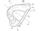
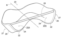
- the method for creating image data of a dental model is a method for creating image data of a lower denture base 10 having a reinforcing member 18 shown in FIG. 1 and an upper denture base 20 having a reinforcing member 28 shown in FIG. Is.
- the dental model is not limited to the denture base, and may be another model such as a mouthpiece such as a sprint or a mouth guard or a dental model.
- the dental model also includes, for example, a denture base for display that does not fit into the patient's ridge.
- the mandibular denture base 10 is a resin-made dental model composed of a crown 12, an inner side wall portion 14, and an outer wall portion 16, and a reinforcing member 18 is integrally formed.
- the mandibular denture base 10 in FIG. 1 is placed on a horizontal plane, and the central axis A in FIG. 1 overlaps with the median line in the oral cavity.
- the upper left side in FIG. 1, which is the lip side along the central axis A is referred to as the "front side”
- the lower right side in FIG. 1, which is the throat side along the central axis A is referred to as the "back side”.
- the terms "upper side” and “lower side” mean the vertical direction in a state where the mandibular denture base 10 is fitted to the mandibular ridge as shown in FIG.
- FIG. 1 is a perspective view of the mandibular denture base 10 as viewed from the upper front surface side.
- the term “inside” refers to the side closer to the central axis A than the top 12 in a plan view (see FIGS.
- the top portion 12 is a horseshoe-shaped (that is, U-shaped) plate-shaped member in a plan view.
- the inner side wall portion 14 is a plate-shaped member provided on the inner edge portion of the U-shape of the top portion 12 so as to hang down from the top portion 12.
- the outer wall portion 16 is a plate-shaped member provided on the outer edge portion of the U-shape of the top portion 12 so as to hang down from the top portion 12.
- the mandibular denture base 10 has a horseshoe-shaped (that is, U-shaped) recess 10A surrounded by a crown 12, an inner side wall portion 14, and an outer wall portion 16, and the mandibular ridge is fitted in the recess 10A.
- the back surface of the top 12 is a portion that covers the upper surface of the mandibular ridge.
- the back surface of the inner wall surface portion 14 is a portion that covers the inner wall surface on the lingual side of the mandibular ridge.
- the back surface of the outer side wall portion 16 is a portion that covers the outer wall surface on the buccal mucosal side of the mandibular ridge.
- a plurality of recesses 10B are formed on the top portion 12 from the front side to the back side (that is, the rear side).
- seven recesses 10B corresponding to seven artificial teeth from the central incisor located on the anterior side to the second molar located on the posterior side are formed across the central axis A.
- the present disclosure is not limited to this, and the number of recesses 10B can be arbitrarily set.
- the terminal portion 17 of the main body located further back than the recess of the second molar is the end portion of the region corresponding to the retromoral pad of the mandibular ridge.
- the reinforcing member 18 of the mandibular denture base 10 reinforces the side wall portion of the recess 10A.
- the reinforcing member 18 is a single rod-shaped member that connects the lower ends of the front surfaces of the left and right inner side wall portions 14 of the recess 10A.
- the rod-shaped member of the reinforcing member 18 connects the end portions 17 on the inner side of the oral cavity of the left and right inner side wall portions 14 of the recess 10A and intersects the central axis A.
- the reinforcing member 18 in the lower jaw is removed after modeling, but is not limited to a rod-shaped object, and if the side wall portion of the recess 10A can be reinforced and can be removed, for example, a plate shape or an arch shape. Etc., any other shape can be adopted.
- the reinforcing member 18 is a single rod-shaped member, it can be easily designed and manufactured. Further, the number of the reinforcing members 18 is also 1 or more, which is arbitrary.
- the connecting position of the reinforcing member can be changed as appropriate.
- the terminal portion 17 located on the inner side along the central axis A has the largest distance between the inner side wall portion 14 and the outer wall portion 16 adjacent to each other with the recess 10A interposed therebetween. Since it is a part that expands greatly, it is most easily deformed during modeling due to its structural characteristics. Therefore, when one rod-shaped member is used as the reinforcing member, it is preferable that the reinforcing member connects the terminal portion 17 which is the inner terminal portion of the left and right inner side wall portions 14.
- the positions of the lower ends of the inner side wall portion 14 and the outer wall portion 16 are farthest from the top portion 12 in the vertical direction.
- the top portion 12 connects the inner side wall portion 14 and the outer wall portion 16 adjacent to each other with the recess 10A interposed therebetween. Therefore, since the amount of deformation at the lower end is particularly large, when one rod-shaped member is used as the reinforcing member, it is preferable that the reinforcing member connects the lower ends of the left and right inner side wall portions 14.
- the reinforcing member 18 connects and connects the lower ends of the end portions 17, which are the end portions on the back side, on the front surfaces of the left and right inner side wall portions 14.
- the maxillary denture base 20 shown in FIG. 2 is a resin-made dental model composed of a bottom portion 22, an inner side wall portion 24, and an outer wall portion 26, and a reinforcing member 28 is integrally formed.
- the maxillary denture base 20 in FIG. 2 is placed on a horizontal plane, and the central axis B in FIG. 2 overlaps with the median line in the oral cavity.
- the lip side (upper left side in FIG. 2) along the central axis B is referred to as the "front side”
- the throat side (lower right side in FIG. 2) along the central axis B is referred to as the "back side”.
- the terms "upper” and “lower” in the maxillary denture base 20 are used in the vertical direction in a state where the maxillary denture base 20 is fitted to the maxillary ridge as shown in FIG. Means.
- FIG. 2 is a perspective view of the maxillary denture base 20 as a bird's-eye view from the upper back surface side.
- the term “inner” in the maxillary denture base 20 refers to the side closer to the central axis B (tongue) than the bottom 22 in a plan view (see FIG. 12) when the back surface of the bottom 22 is viewed from the front.
- the term “outside” as well as “side” means the side (buccal side) farther from the central axis B than the bottom 22.
- the bottom portion 22 is a horseshoe-shaped (that is, U-shaped) plate-shaped member in a plan view.
- the inner side wall portion 24 is a plate-shaped member provided on the inner edge portion of the U-shape of the bottom portion 22 so as to hang down from the bottom portion 22.
- the outer wall portion 26 is a plate-shaped member provided on the U-shaped outer edge portion of the bottom portion 22 so as to hang down from the bottom portion 22.
- the maxillary denture base 20 has a horseshoe-shaped (that is, U-shaped) recess 20A surrounded by a bottom portion 22, an inner side wall portion 24, and an outer wall portion 26, and the maxillary ridge is fitted in the recess 20A.
- the back surface of the bottom 22 is a portion that covers the lower surface of the maxillary ridge.
- the back surface of the inner side wall portion 24 is a portion that covers the inner side wall surface of the maxillary ridge and the palatal mucosa.
- the back surface of the outer side wall portion 26 is a portion that covers the side wall surface on the buccal mucosal side of the maxillary ridge.
- a plurality of recesses 20B are formed in the bottom portion 22 from the front side to the back side.
- the number of recesses 20B can be arbitrarily set as in the case of the mandibular denture base.
- the terminal portion 27 of the main body is the end portion of the region further back than the recess of the second molar.
- the reinforcing member 28 of the maxillary denture base 20 reinforces the side wall portion of the recess 20A.
- the reinforcing member 28 is a single rod-shaped member that connects the upper ends of the back surfaces of the left and right inner side wall portions 24 of the recess 20A.
- the rod-shaped member of the reinforcing member 28 connects the end portions 27 on the inner side of the oral cavity of the left and right outer wall portions 26 of the recess 20A and intersects the central axis A.
- the meaning of "rod-shaped member" in the upper jaw is the same as in the case of the lower jaw.
- the reinforcing member 28 in the upper jaw is removed after modeling as in the case of the lower jaw, but it is not limited to a rod-shaped object, and if the side wall portion of the recess 20A can be reinforced and can be removed, it is possible.
- any other shape such as a plate shape or an arch shape can be adopted.
- the reinforcing member 28 is a linear rod-shaped member, it can be easily designed and manufactured. Further, the number of the reinforcing members 28 is one or more, which is arbitrary.
- the connecting position of the reinforcing member can be changed as appropriate.
- the terminal portion 27 located on the inner side along the central axis B has the largest distance between the inner side wall portion 24 and the outer wall portion 26 adjacent to each other with the recess 20A interposed therebetween. Since it is a part that expands greatly, it is most easily deformed during modeling due to its structural characteristics. Therefore, when one rod-shaped member is used as the reinforcing member, it is preferable that the reinforcing member connects the terminal portions 27, which are the left and right inner terminal portions.
- the position of the upper end of the outer wall portion 26 is the farthest from the apex 12 to the upper side in the vertical direction.
- the top portion 12 connects the inner side wall portion 24 and the outer wall portion 26 that are adjacent to each other with the recess 20A interposed therebetween. Therefore, since the amount of deformation at the upper end is particularly large, when one rod-shaped member is used as the reinforcing member, it is preferable that the reinforcing member connects the upper ends of the left and right outer wall portions 26.
- the reinforcing member 28 connects and connects the upper ends of the end portions 27, which are the end portions on the back side, on the back surfaces of the left and right outer wall portions 26.
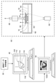
- the dental model manufacturing apparatus includes an image data acquisition device 30, a design image data creating device 40, a manufacturing image data creating device 50, and a modeling device 60.
- the image data acquisition device 30 is, for example, a 3D scanner, and is connected to the design image data creation device 40.
- the image data acquisition device 30 is, for example, an impression that reflects the shape of the mandibular ridge of the patient (hereinafter referred to as “mandibular impression”), or a mandible that is actually used by the patient and does not have a reinforcing member.
- the mandibular prosthesis is scanned to obtain image data showing the three-dimensional (3D) shape of the main body of the mandibular prosthesis.
- the mandible is scanned directly from the patient's oral cavity to obtain image data showing the three-dimensional (3D) shape of the mandibular ridge.
- the acquired image data is input to the design image data creation device 40.
- the image data acquisition device 30 is not essential, and for example, 3D shape data created by arbitrary software and prepared in advance may be input to the design image data creation device 40.
- the present disclosure is not limited to this.
- an impression that reflects the shape of the patient's maxillary ridge (that is, the maxilla). Impression), maxillary denture base, etc. that is actually used, or image data of the maxillary denture base, etc., based on the shape of the maxillary ridge, etc. scanned directly from the patient's oral cavity.
- the horseshoe-shaped dental sculpture is, for example, a denture base, a mouthpiece, a sprint, or the like.
- the design image data creating device 40 of the present embodiment is, for example, a general-purpose personal computer including a central integrated circuit (CPU), a storage device, an input device, and a display device (that is, an output device) (not shown). Etc. can be used.
- the design image data creation device 40 has a 3D-CAD function as an image processing program for processing image data.
- the design image data creation device 40 corresponds to the "image data creation device" of the present disclosure.
- a manufacturing image data creating device 50 is connected to the design image data creating device 40.
- the design image data creation device 40 includes an arithmetic unit 42 having an image data acquisition unit 42A and an image data creation unit 42B.
- the image data acquisition unit 42A acquires, for example, image data of the main body of the mandibular ridge, the mandibular impression, or the mandibular denture base from the image data acquisition device 30.
- the image data creation unit 42B is an area for executing the 3D-CAD function, and the image data of the lower jaw ridge, the lower jaw impression, or the main body of the lower jaw prosthesis acquired by the image data acquisition device 30 is used as an actual dental model.
- Create an image data of a dental model by processing it into a shape suitable for.
- the processing of the image data is, for example, deletion of the shape of an unnecessary portion included in the scanned image immediately after scanning, integration of the image data when a plurality of image data are acquired, and the like.
- the image data of the main body of the mandibular prosthesis acquired from the image data acquisition device 30 is used in step S10 in FIG. 5, the image data of the main body of the mandibular prosthesis acquired without processing is used as it is for the dental model. It may be used as image data of.
- the image data creating unit 42B creates the reinforcing member data 118 which is the image data of the reinforcing member.
- the image data creation unit 42B uses the image data of the dental model and the reinforcing member data 118 as data constituting a single data indicating the shape of one lower denture base. Concatenate each by associating them with a single data. Image data 100 for design is created by concatenation.
- the image data of the dental model and the reinforcing member data 118 are integrated.
- the image data 100 for design is selected by clicking in the virtual 3D coordinate space
- the image data of the dental model and the reinforcing member data 118 are not separated from each other, and the image data and the reinforcement of the dental model are reinforced.
- the member data 118 can be moved integrally.
- the image data creation method is implemented by the 3D-CAD of the design image data creation device 40.
- the designer can move, arrange, and rotate the image data of the dental model to an arbitrary position in the virtual 3D coordinate space on the display of the design image data creation device 40.
- the shape of the reinforcing member data 118 is created by using one or more features, and the created reinforcing member data 118 is moved and superimposed on the image data of the dental model in the 3D coordinate space, and is predetermined. Can be connected to each other at the position of.
- CAD is more advantageous in design work than CAM.
- CAD usually has more types of features that can be adopted than CAM.
- the degree of freedom of movement and rotation of the reinforcing member data 118 is higher than in the case of CAM.
- CAD it is easy to partially change the shape of the image data of the dental model or the reinforcing member data 118 while maintaining the connected state between the image data of the dental model and the reinforcing member data 118. Therefore, by using CAD, it becomes possible to efficiently and accurately create the image data 100 for design.
- the image data creation method a case where the processing of steps S10 and S20 in FIG. 5 is performed by a human operating the image data acquisition device 30 and the design image data creation device 40 is exemplified.
- this disclosure is not limited to this.
- you may create an image data creation program that causes a computer to execute the processes of steps S10 and S20.
- the image data acquisition device 30 and the design image data creation device 40 may be made to execute the processes of steps S10 and S20 by the created image data creation program to create the image data 100 for design.
- the image data of the dental model in step S10 may be acquired by processing the image data of the mandibular ridge, the mandibular impression, or the mandibular denture base acquired by the image data acquisition device as described above. ..
- the image data of the dental model of the mandibular denture base existing in advance may be read into a 3D scanner or the like and acquired.
- the image data 100 for design may be created by directly connecting the acquired image data with the reinforcing member data 118 without processing the acquired image data.
- the image data 100 for designing the mandibular denture base created by CAD is exemplified.
- the image data 100 for design is, as a data area in the virtual 3D coordinate space, in the apex region 112 corresponding to the apex of the actual mandibular denture base, the inner side wall region 114 corresponding to the inner side wall portion, and the outer wall portion. It has a corresponding outer wall area 116. Further, the reinforcing member data 118 is arranged between the left and right inner side wall portions 114.
- the image data 100 for design is input to the manufacturing image data creating device 50.
- the manufacturing image data creation device 50 is a computer equipped with a central integrated circuit (not shown), a storage device, an input / output device, and the like, and has a CAM function.
- a modeling device 60 is connected to the manufacturing image data creating device 50.
- the manufacturing image data creating device 50 processes the design image data 100 in the virtual 3D coordinate space, and the manufacturing image data 100A for modeling with the modeling device 60 is provided. Will be created.
- modeling conditions such as an arrangement angle and distance of the mandibular denture base with respect to the build table of the modeling apparatus 60 are set, and the set modeling conditions are reflected in the image data 100A for manufacturing by CAM.
- CAM creates support pin data for modeling.
- the image data 100A for manufacturing processed by CAM has a build table area 166 corresponding to a build table as a data area in a virtual 3D coordinate space, and a plurality of support pins corresponding to support pins. Suspended by region 170. Reinforcing member data 118 is exposed between the plurality of support pin regions 170.
- the image data 100A for manufacturing is input to the modeling apparatus 60.
- the modeling apparatus 60 is a hanging type 3D printer, and a dental model is modeled by a liquid tank photopolymerization method.
- the modeling device 60 includes a liquid tank 62 for storing a liquid photocurable liquid resin 64, a build table 66 as a base for dental modeling, and a hanging member 68 for suspending the build table 66.
- a light irradiating machine 69 for irradiating light is provided on the lower surface of the build table 66.
- the modeling device 60 of the present embodiment is a hanging type, but the present disclosure is not limited to this. Further, in the present embodiment, DLP (Digital Light Processing) stereolithography is exemplified, but the present invention is not limited to this, and for example, SLA (Stereolithography) stereolithography and LCD (Liquid Crystal Display) stereolithography are used. Other modeling methods such as modeling or stereolithography of the inkjet method may be adopted.
- DLP Digital Light Processing stereolithography
- SLA Stepolithography
- LCD Liquid Crystal Display
- the light irradiator 69 emits light having a predetermined wavelength such as ultraviolet rays toward the lower side of the build table 66 immersed in the liquid tank 62 based on the image data 100A for manufacturing input to the modeling apparatus 60. Irradiate selectively. By light irradiation, the liquid resin 64 is photopolymerized and selectively cured in the formation region 63 having a certain thickness, and a resin layer of the object to be modeled is formed. Then, by moving the suspending member 68 to the upper side in FIG. 1, the build table 66 rises by the set thickness of the resin layer.
- a predetermined wavelength such as ultraviolet rays
- FIG. 3 illustrates a state in which a part of the mandibular denture base 10 being modeled is suspended by a support pin 70 extending from the lower surface of the build table 66.
- step S50 in FIG. 5 the mandibular denture base 10 having the reinforcing member 18 as shown in FIG. 1 is finally formed by repeating the ascending of the build table 66 and the irradiation of light.
- FIG. 7 illustrates a mandibular denture base 10 in which a connection mark 19 of the reinforcing member 18 is formed on the outer surface of the left and right inner side wall portions 14 of the recess 10A after the reinforcing member 18 is removed.
- FIG. 8 illustrates a maxillary denture base 20 in which a connection mark 29 of the reinforcing member 28 is formed on the inner surface of the left and right outer wall portions 26 of the recess 20A after the reinforcing member 28 is removed. ..
- connection marks may remain as they are on the surface of the denture base in a state where they are actually fitted to the ridge, or may be obscured by surface treatment.
- the shape of the connecting marks remaining on the surface is arbitrary depending on the shape of the connecting portion of the reinforcing member.
- the connection mark is not conspicuous on the surface of the denture base, for example, when the surface is peeled off by about several microns and the resin is observed on the peeled part with a microscope, the resin of the connecting part of the reinforcing member and the periphery of the connecting part. Based on the difference in properties from the resin of the above, it can be determined whether or not the reinforcing member is provided.
- the end portion 17, which is the inner end portion that is easily deformed is connected to the inner side wall portion 14 and the outer wall portion 16, so that the connection marks are formed on the left and right end portions 17. It is preferable that it is. Further, since the lower ends of the inner side wall portion 14 and the outer wall portion 16 are regions where the amount of deformation is large, it is preferable that the connection marks are formed at the lower ends of the left and right inner side wall portions 14. In the present embodiment, the connection mark 19 is formed at the lower end of the end portion 17 on the front back surface of the left and right inner side wall portions 14.
- the end portion 27, which is the inner end portion that is easily deformed, is connected to the inner side wall portion 24 and the outer wall portion 26, so that the connection mark is formed on the end portion 27. It is preferable to have. Further, since the upper ends of the inner side wall portion 24 and the outer wall portion 26 are regions where the amount of deformation is large, it is preferable that the connection marks are formed at the upper ends of the left and right outer wall portions 26. In the present embodiment, the connection mark 29 is formed at the upper end of the terminal portion 27 on the back surface of the left and right outer wall portions 26.
- the present inventors use six mandibular denture bases 10 modeled using the image data creation method according to the present embodiment as the first to sixth embodiments, respectively. I prepared it.
- the connecting positions of the reinforcing members 18 of the mandibular denture base 10 of the first to sixth embodiments are different from each other.
- the upper side illustrates the state of the mandibular denture base 10 in a plan view
- the lower side shows the mandibular denture base 10 from the back side to the front side along the central axis A.
- the state of the side view when viewed is exemplified.
- the reinforcing member 18 of the first embodiment is a linear rod-shaped member connected to the upper part of the end portion on the inner side between the left and right inner side wall portions of the mandibular denture base 10.
- the reinforcing member 18 of the second embodiment has a U-shape connected to the upper part of the end portion on the inner side between the left and right inner side wall portions of the mandibular denture base 10. It is a rod-shaped member.
- the reinforcing member 18 of the third embodiment has a linear rod shape connected to the lower part of the end portion on the inner side between the left and right inner side wall portions of the mandibular denture base 10. It is a member.
- the reinforcing member 18 of the fourth embodiment is connected to the upper part of the position of the recess 10A of the first premolar on the anterior side between the left and right inner side walls of the mandibular denture base 10. It is a linear rod-shaped member.
- the reinforcing member 18 of the fifth embodiment is connected to the lower part of the position of the recess 10A of the first premolar on the anterior side between the left and right inner side walls of the mandibular denture base 10. It is a linear rod-shaped member.
- the reinforcing member 18 of the sixth embodiment is connected to the lower part of the position of the recess 10A of the first molar on the inner side between the left and right inner side walls of the mandibular denture base 10. It is a linear rod-shaped member.
- the present inventors have modeled the mandibular denture base according to the first comparative example, which does not have a reinforcing member and consists only of the main body.
- the shape of the main body of the mandibular denture base according to the first comparative example is the same as the shape of the main body of the mandibular denture base 10 of the first to sixth embodiments.
- "Geomagic design X” manufactured by 3D Systems Co., Ltd. is used to create image data 100 for each design of the first to sixth embodiments and the first comparative example prior to modeling. It was adopted as a 3D-CAD of a design image data creation device. Then, the created image data 100 for design was input to "caraCAM 2.0" manufactured by Kulzer as a CAM of the manufacturing image data creation device, and was arranged at a predetermined angle with respect to the build table area. Then, after the support pin area was extended and supported vertically from the build table area with respect to the arranged image data by the CAM, the image data 100A for manufacturing a plurality of continuous slice data was created.
- the image data 100A for manufacturing was transferred to the 3D printer "caraPrint 4.0" manufactured by Kulzer as a modeling device, and modeling was performed.
- the 3D printer ink used for modeling was "dima Print Denture Base” manufactured by Kulzer.
- the mandibular denture base obtained by modeling was washed, the support pin was excised, and then post-cure was performed.
- the device used for post-cure was "HiLite power 3D” manufactured by Kulzer.
- the denture base after post-cure is 3D image data of the front surface on the denture (artificial tooth) side and the back surface on the ridge (mucosa) side. was taken in.
- the captured 3D image data was input to the reverse engineering software "Geomagic design X" manufactured by 3D Systems, superposed on the image data 100 for design, and the deviation calculation was performed to calculate the matching score.
- the matching score is based on the displacement between the 3D image data after modeling captured in each of the first to sixth examples and the first comparative example and the image data 100 for design created before modeling. Show the evaluation. Specifically, the displacement (that is, the difference) is calculated with respect to the coordinates of the positions of the surfaces corresponding to each other between the 3D image data after modeling and the image data 100 for designing before modeling. Then, the ratio of the portion where the calculated displacement is plus (+) / minus ( ⁇ ) 200 ⁇ m or less between the two data is calculated as the matching score. The higher the matching score value, the higher the modeling accuracy.
- the matching score on the front side was 70 and the matching score on the back side was 80.
- the matching score of the first comparative example was the lowest on both the front side and the back side of the compared mandibular denture bases.
- FIG. 11A three regions patterned according to displacement are superimposed and exemplified on the front surface side of the image data 100Z for design of the first comparative example.
- FIG. 11B three regions patterned according to the displacement are superimposed and exemplified on the back surface side of the image data 100Z for design of the first comparative example.
- FIG. 11A on the front surface side, in the region of the left and right outer wall portions 16 having the solid diagonal line pattern, 0.1 ⁇ m or more, the upper side of the outer wall portion 16 (that is, the paper surface of FIG. 11A). There is a displacement toward the upper side in the vertical direction that penetrates vertically.
- FIG. 11B on the back surface side, in the region of the left and right outer wall portions 16 having the dotted diagonal line pattern, 0.1 ⁇ m or more, the lower side of the outer wall portion 16 (that is, the paper surface of FIG. 11B is vertical). There is a displacement toward the lower side in the vertical direction that penetrates through.
- the white region without the solid diagonal line pattern or the dotted diagonal line pattern is a portion where the generated displacement is less than 0.1 ⁇ m. From FIGS. 11A and 11B, in the case of the mandibular denture base according to the first comparative example having no reinforcing member, the displacement of the inner side wall portion 14 and the outer wall portion 16 on the inner side including the retromoral pad is particularly large. I understand.
- the matching scores of the first to sixth embodiments were 72 or more on the front surface side and 81 or more on the back surface side, both of which were higher than those of the first comparative example. ..
- the matching score of the third embodiment in which the reinforcing member 18 of the linear rod-shaped member shown in FIG. 9C is connected to the lower part of the end portion on the inner side between the left and right inner side wall portions is as follows. It was 95 on the front side and 97 on the back side, which was the highest among the mandibular denture bases in comparison.
- the present inventors modeld two maxillary denture bases 20 by using the image data creation method according to the present embodiment, and made them into the seventh embodiment and the eighth, respectively.
- the connecting positions of the reinforcing members 28 of the maxillary denture base 20 of the seventh embodiment and the eighth embodiment are different from each other.
- the reinforcing member 28 of the seventh embodiment is a linear rod-shaped member connected to the upper part of the end portion 27 on the back side between the left and right outer wall portions of the maxillary denture base 20.
- the reinforcing member 28 of the rod-shaped member connecting the left and right inner side wall portions is further provided. Has been done.
- the reinforcing member 28 between the outer wall portion and the reinforcing member 28 between the inner side wall portions in the eighth embodiment have substantially the same diameter, and are arranged at substantially overlapping positions in the vertical direction.
- the present inventors have modeled the maxillary denture base according to the second comparative example having no reinforcing member, as in the case of the mandibular denture base.
- the shape of the maxillary denture base according to the second comparative example is the same as the shape of the maxillary denture base 20 of the seventh embodiment and the eighth embodiment except for the reinforcing member.
- image data 200 for each design of the 7th embodiment, the 8th embodiment and the 2nd comparative example are created under the same conditions as in the case of the mandibular denture base, and the created image data for the design is created.
- Image data 200A for manufacturing was created using the image data 200.
- the maxillary denture base was modeled based on the image data 200A for each production.
- the matching score on the front side was 88, and the matching score on the back side was 88.
- the matching score values of the second comparative examples were all the lowest.
- the matching score of the 7th embodiment and the matching score of the 8th embodiment were both 93 on the front side. On the back side, the matching score of the 7th example was 92, while the matching score of the 8th example was 94.
- the reinforcing member 28 is provided both between the left and right outer wall portions of the maxillary denture base 20 and between the left and right inner side wall portions as in the eighth embodiment, the left and right outer wall portions are provided. The matching score is higher than when the reinforcing member 28 is provided only between the two.
- the reinforcing members 18 and 28 are one rod-shaped member connecting the left and right side wall portions of the recesses 10A and 20A, the reinforcing members 18 and 28 can have a simple structure.
- the rod-shaped member of the reinforcing member 18 of the mandibular denture base 10 connects the end portion 17 which is the inner end portion of the front surface of the left and right inner side wall portions 14.
- the rod-shaped member of the reinforcing member 28 of the maxillary denture base 20 connects the end portion 27 which is the back end portion of the back surface of the left and right outer wall portions 26.
- the rod-shaped member as the reinforcing member 18 of the mandibular denture base 10 connects the lower ends having a particularly large amount of deformation among the left and right inner side wall portions 14, the modeling accuracy of the mandibular denture base 10 is improved. It can be further enhanced.
- the rod-shaped member of the reinforcing member 28 of the maxillary denture base 20 connects the upper ends of the left and right outer wall portions 26 having a particularly large amount of deformation, the modeling accuracy of the maxillary denture base 20 is further improved. Can be enhanced.
- the reinforcing member 28 of the maxillary denture base 20 further has a rod-shaped member connecting the front surfaces of the left and right inner side wall portions 24 of the recess 20A in the maxillary denture base 20. Therefore, the modeling accuracy of the maxillary denture base 20 can be further improved.
- the dental model in the modeling process, the parts that are easily deformed during modeling are reinforced by the reinforcing members 18 and 28, so that the dental model can be manufactured with good and stable modeling accuracy.
- the dental model is the mandibular denture base 10 and the maxillary denture base 20 that fit into the patient's ridge.
- the reinforcing member has good modeling accuracy, excellent stability of modeling accuracy, and easily reinforces the denture base.
- Image data can be formed.
- a server as a computer having an arithmetic device for executing an image data creation method is provided separately from the design image data creation device, and the image data creation system for the dental model or the dental model centered on the server. Manufacturing system may be configured.
- the server can be connected to all of the image data acquisition device, the design image data creation device, the manufacturing image data creation device, and the modeling device, and can control the operation of each.
- an image data creation system for a dental model or a manufacturing system for a dental model By constructing an image data creation system for a dental model or a manufacturing system for a dental model, it becomes possible to improve the efficiency of a series of work related to the image data creation of the dental model and the production of the dental model. , It becomes possible to operate each facility efficiently.
- present disclosure can be configured by partially combining the configurations exemplified in FIGS. 1 to 13.
- present disclosure includes various embodiments not described above, and the technical scope of the present disclosure is defined only by the matters specifying the invention within the scope of claims from the above description. be.
Landscapes
- Health & Medical Sciences (AREA)
- Oral & Maxillofacial Surgery (AREA)
- Dentistry (AREA)
- Epidemiology (AREA)
- Life Sciences & Earth Sciences (AREA)
- Animal Behavior & Ethology (AREA)
- General Health & Medical Sciences (AREA)
- Public Health (AREA)
- Veterinary Medicine (AREA)
- Engineering & Computer Science (AREA)
- Manufacturing & Machinery (AREA)
- Chemical & Material Sciences (AREA)
- Materials Engineering (AREA)
- Dental Prosthetics (AREA)
Priority Applications (4)
| Application Number | Priority Date | Filing Date | Title |
|---|---|---|---|
| KR1020237008652A KR20230050428A (ko) | 2020-08-31 | 2021-08-18 | 치과 조형물의 화상 데이터 작성 방법, 치과 조형물의 화상 데이터 작성 장치, 치과 조형물의 화상 데이터 작성 프로그램, 치과 조형물의 제조 방법 및 치과 조형물 |
| JP2022544504A JP7524329B2 (ja) | 2020-08-31 | 2021-08-18 | 歯科造形物の画像データ作成方法、歯科造形物の画像データ作成装置、歯科造形物の画像データ作成プログラム、歯科造形物の製造方法及び歯科造形物 |
| EP21861357.8A EP4205696A4 (en) | 2020-08-31 | 2021-08-18 | METHOD FOR CREATING DENTAL MOLDED ARTICLE IMAGE DATA, DEVICE FOR CREATING DENTAL MOLDED ARTICLE IMAGE DATA, PROGRAM FOR CREATING DENTAL MOLDED ARTICLE IMAGE DATA, METHOD FOR MANUFACTURING DENTAL MOLDED ARTICLE, AND DENTAL MOLDED ARTICLE |
| US18/042,855 US20230301759A1 (en) | 2020-08-31 | 2021-08-18 | Method for creating image data of dental shaped object, apparatus for creating image data of dental shaped object, program for creating image data of dental shaped object, method for manufacturing dental shaped object, and dental shaped object |
Applications Claiming Priority (2)
| Application Number | Priority Date | Filing Date | Title |
|---|---|---|---|
| JP2020-146114 | 2020-08-31 | ||
| JP2020146114 | 2020-08-31 |
Publications (1)
| Publication Number | Publication Date |
|---|---|
| WO2022044929A1 true WO2022044929A1 (ja) | 2022-03-03 |
Family
ID=80354244
Family Applications (1)
| Application Number | Title | Priority Date | Filing Date |
|---|---|---|---|
| PCT/JP2021/030231 Ceased WO2022044929A1 (ja) | 2020-08-31 | 2021-08-18 | 歯科造形物の画像データ作成方法、歯科造形物の画像データ作成装置、歯科造形物の画像データ作成プログラム、歯科造形物の製造方法及び歯科造形物 |
Country Status (5)
| Country | Link |
|---|---|
| US (1) | US20230301759A1 (https=) |
| EP (1) | EP4205696A4 (https=) |
| JP (1) | JP7524329B2 (https=) |
| KR (1) | KR20230050428A (https=) |
| WO (1) | WO2022044929A1 (https=) |
Citations (7)
| Publication number | Priority date | Publication date | Assignee | Title |
|---|---|---|---|---|
| WO2010058822A1 (ja) | 2008-11-20 | 2010-05-27 | 国立大学法人東京医科歯科大学 | 有床義歯及びその製造方法 |
| JP2010540087A (ja) * | 2007-09-27 | 2010-12-24 | スリーエム イノベイティブ プロパティズ カンパニー | 歯科矯正技工器具を製造するための歯科模型のデジタル形成方法 |
| WO2014024830A1 (ja) * | 2012-08-08 | 2014-02-13 | 有限会社 ディーシーエル タニモト | 仮義歯床または仮部分義歯床の作製装置、および仮義歯床または仮部分義歯床の作製方法 |
| JP2019141553A (ja) * | 2018-02-24 | 2019-08-29 | 佐藤 哲也 | 3dプリンターを利用した維持装置と義歯床の一体型義歯。 |
| WO2019213476A1 (en) * | 2018-05-03 | 2019-11-07 | Dentsply Sirona Inc. | Methods of three-dimensional printing for fabricating a dental appliance |
| JP2020146114A (ja) | 2019-03-11 | 2020-09-17 | 株式会社オリンピア | 遊技機 |
| US20200390528A1 (en) * | 2019-06-17 | 2020-12-17 | Dentsply Sirona Inc. | Additively manufactured denture base with bracing body |
Family Cites Families (7)
| Publication number | Priority date | Publication date | Assignee | Title |
|---|---|---|---|---|
| EP2014254B1 (en) | 2007-06-07 | 2018-10-31 | Nobel Biocare Services AG | Method and sintered product for forming a dental bridge |
| CN104363856B (zh) | 2012-05-10 | 2016-11-16 | 瑞尼斯豪公司 | 制造物品的方法 |
| US10383713B2 (en) | 2012-05-10 | 2019-08-20 | Renishaw Plc | Method of manufacturing an article |
| DE202014010392U1 (de) | 2014-09-12 | 2015-06-17 | Amann Girrbach Ag | Sinterrohling |
| US10449016B2 (en) | 2014-09-19 | 2019-10-22 | Align Technology, Inc. | Arch adjustment appliance |
| US20180304541A1 (en) | 2017-04-19 | 2018-10-25 | Carbon, Inc. | 3d lattice supports for additive manufacturing |
| US11511485B2 (en) * | 2019-04-02 | 2022-11-29 | Align Technology, Inc. | 3D printed objects with selective overcure regions |
-
2021
- 2021-08-18 JP JP2022544504A patent/JP7524329B2/ja active Active
- 2021-08-18 WO PCT/JP2021/030231 patent/WO2022044929A1/ja not_active Ceased
- 2021-08-18 EP EP21861357.8A patent/EP4205696A4/en active Pending
- 2021-08-18 KR KR1020237008652A patent/KR20230050428A/ko not_active Ceased
- 2021-08-18 US US18/042,855 patent/US20230301759A1/en active Pending
Patent Citations (7)
| Publication number | Priority date | Publication date | Assignee | Title |
|---|---|---|---|---|
| JP2010540087A (ja) * | 2007-09-27 | 2010-12-24 | スリーエム イノベイティブ プロパティズ カンパニー | 歯科矯正技工器具を製造するための歯科模型のデジタル形成方法 |
| WO2010058822A1 (ja) | 2008-11-20 | 2010-05-27 | 国立大学法人東京医科歯科大学 | 有床義歯及びその製造方法 |
| WO2014024830A1 (ja) * | 2012-08-08 | 2014-02-13 | 有限会社 ディーシーエル タニモト | 仮義歯床または仮部分義歯床の作製装置、および仮義歯床または仮部分義歯床の作製方法 |
| JP2019141553A (ja) * | 2018-02-24 | 2019-08-29 | 佐藤 哲也 | 3dプリンターを利用した維持装置と義歯床の一体型義歯。 |
| WO2019213476A1 (en) * | 2018-05-03 | 2019-11-07 | Dentsply Sirona Inc. | Methods of three-dimensional printing for fabricating a dental appliance |
| JP2020146114A (ja) | 2019-03-11 | 2020-09-17 | 株式会社オリンピア | 遊技機 |
| US20200390528A1 (en) * | 2019-06-17 | 2020-12-17 | Dentsply Sirona Inc. | Additively manufactured denture base with bracing body |
Non-Patent Citations (1)
| Title |
|---|
| See also references of EP4205696A4 |
Also Published As
| Publication number | Publication date |
|---|---|
| KR20230050428A (ko) | 2023-04-14 |
| JPWO2022044929A1 (https=) | 2022-03-03 |
| JP7524329B2 (ja) | 2024-07-29 |
| EP4205696A4 (en) | 2024-09-18 |
| EP4205696A1 (en) | 2023-07-05 |
| US20230301759A1 (en) | 2023-09-28 |
Similar Documents
| Publication | Publication Date | Title |
|---|---|---|
| US11771535B2 (en) | Apparatus and methods of making denture devices | |
| US20240335253A1 (en) | System For Preparing Teeth For The Placement Of Veneers | |
| US10470855B2 (en) | Apparatus and methods of making denture devices | |
| US11504214B2 (en) | Devices, systems, and computer-implemented methods for dental attachment templates | |
| US10568723B2 (en) | Apparatus and methods of making denture devices | |
| US9675432B2 (en) | Method and apparatus for preparing removable dental prosthesis | |
| CN104644276B (zh) | 制造牙齿矫治器的方法以及牙齿矫治器 | |
| CN106037967B (zh) | 基于3d打印技术的即刻全口义齿或半口义齿的制作方法 | |
| CN107198586B (zh) | 一种无牙颌功能压力个别托盘的数字设计制作方法 | |
| EP3777756B1 (en) | Modeling a digital design of a denture | |
| JP5767252B2 (ja) | Camによって製作される歯モデルにおける着脱可能構成要素の支持 | |
| CN105982742A (zh) | 牙齿矫治器及其制造方法、数字化牙齿模型的填倒凹处理 | |
| JP2019528997A (ja) | 人工歯用の共通配置支持体 | |
| WO2020250976A1 (ja) | マウスピース及びマウスピースの製造方法 | |
| CN107260351A (zh) | 用于监测牙齿矫治状态的方法 | |
| EP3982870B1 (en) | Additively manufactured denture base with bracing body | |
| JP4751144B2 (ja) | 造形データ作成システム、製造方法および造形データ作成プログラム | |
| JP2023145196A (ja) | 上顎の歯科造形物の画像データ作成方法、下顎の歯科造形物の画像データ作成方法、上顎の歯科造形物の製造方法、下顎の歯科造形物の製造方法、上顎の有床義歯、下顎の歯科造形物、及び、歯科造形物セット | |
| JP2019195584A (ja) | 歯冠修復物の作製方法、作業模型の製造装置及び作業模型 | |
| WO2022044929A1 (ja) | 歯科造形物の画像データ作成方法、歯科造形物の画像データ作成装置、歯科造形物の画像データ作成プログラム、歯科造形物の製造方法及び歯科造形物 | |
| Hong et al. | Surveyed restoration and RPD framework design utilizing electronic surveying | |
| JP2021159329A (ja) | 有床義歯の3dデータ取得方法及び有床義歯の製造方法、並びに、義歯床の3dデータ取得方法及び義歯床の製造方法 | |
| US20220242046A1 (en) | Methods of Forming Orthodontic Appliances |
Legal Events
| Date | Code | Title | Description |
|---|---|---|---|
| 121 | Ep: the epo has been informed by wipo that ep was designated in this application |
Ref document number: 21861357 Country of ref document: EP Kind code of ref document: A1 |
|
| ENP | Entry into the national phase |
Ref document number: 2022544504 Country of ref document: JP Kind code of ref document: A |
|
| ENP | Entry into the national phase |
Ref document number: 20237008652 Country of ref document: KR Kind code of ref document: A |
|
| NENP | Non-entry into the national phase |
Ref country code: DE |
|
| ENP | Entry into the national phase |
Ref document number: 2021861357 Country of ref document: EP Effective date: 20230331 |